803b manual rev1 6-08 -...
TRANSCRIPT
RESISTANCE/RESISTIVITY PROBE
Model 803B
Operating Instructions
6/08

2
1.0 INTRODUCTION
There exist many applications where the resistance or resistivity properties of static dissipative and insulating type materials are required. ANSI/ASTM D 257 is a standard test method for measuring the "D.C. RESISTANCE OR CONDUCTANCE OF INSULATING MATERIALS". This test method covers direct current procedures for determining the DC insulation resistance, volume resistance, volume resistivity, surface resistance and surface resistivity of electrical insulating materials. ANSI/ESDA STM11.11 and STM11.12 are the latest standards for determining the surface and volume resistance characterization of planer, static dissipative material respectively. Variations of these test methods can be used to measure the resistance of conductive materials
The resistance/resistivity measurements are used for predicting the ability of insulating type materials to dissipate a buildup of electrostatic charge. Materials that are coated, chemically treated or contain an internal antistatic agent have static dissipative characteristics that are a function of the surface resistance/resistivity. On the other hand, materials that are loaded with a conductive material, such as carbon, are volume conductive. In most cases a material that is volume conductive is also surface conductive but there are certain composites or laminates where this rule does not hold true. During the development of new static dissipating materials or coatings, it is necessary to know the material resistance/resistivity in order to predict the static dissipative characteristics. Likewise, it is also necessary to measure this parameter during the evaluation and qualification of existing materials where the expected resistance/resistivity values are known.
In the static control applications a number of military, industry and individual company standards exist that specify the surface and/or volume resistivity as a material specification requirement. Among these additional standards are ESDA standards requiring the measurement of surface and/or volume resistance, Mil Std 883, EIA-541, MIL PRF 81705D plus numerous company specifications such as those issued by Bellcore, Hewlett Packard, IBM, Seagate, etc. ANSI/ASTM D 257 describes several measurement techniques and measuring electrode types for determining resistivity. The ETS Model 803B Resistance/Resistivity Probe is a circular measuring electrode that is based around the concentric ring electrode design specified in the standard. This electrode configuration, shown in Figure 1-1, restricts the measurement path (surface resistivity) to just the area between the two concentric ring electrodes, thus eliminating measurement errors attributed to stray current paths such as those experienced with parallel bar electrodes. The Model 803B is designed such that the measured surface resistance is converted to surface resistivity by multiplying the resistance measurement by a factor of 10.
ESDA STM11.11 defines a specific ASTM D 257 type concentric ring probe for use in measuring the surface resistance of static dissipative material in the range of > 1x 10⁴ to < 1 x 10¹¹ Ohms.

3
ESD DS11.12 utilizes the inner electrode of the S11.11 Probe in conjunction with a flat metal plate electrode to measure volume resistance.
Variations of this procedure enable resistance in the conductive range to also be measured.
Figure 1-1:Model 803B Resistance/Resistivity Probe
2.0 EQUIPMENT DESCRIPTION
The Model 803B Resistance/Resistivity Probe design has been adapted as the industry standard for measuring the resistance characteristics or planar material. This concentric ring probe incorporates a geometrical configuration that provides a x10 multiplication factor to convert the surface resistance measurement to surface resistivity. The Probe is also capable of measuring volume resistance and volume resistivity of material having smooth flat surfaces of at least 2.5" diameter. The ability of the Model 803B Probe to measure materials of this size makes it compatible with the standard specimen size used in most electrostatic parameter testing.
The design of the Model 803B Probe electrode configuration is derived from the applicable formulas set forth in ANSI/ASTM D 257. For the concentric ring design the surface resistivity, ρs, is a function of the ratio between the inner and outer ring diameters as shown in the following formula:
ρs = (D1 + D2) πRm Ohms/sq (D2 - D1) D1 = Outside Diameter of inner ring D2 = Inner Diameter of outer ring Rm = Measured resistance in ohms

4
By properly choosing D1 and D2, the factor (D1 + D2)/(D2 - D1) can be made to equal any reasonable number. In the case of the Model 803B, π(D1 + D2)/ (D2 - D1) equals 10, resulting in a surface resistivity of
ρs = 10 Rm Ohms/square
The numeric value of ρs is actually in Ohms. The designation Ohms/square clarifies the number as a surface resistivity measurement.
ESDA STM11.11 specifies a probe having the Model 803B design specifications. Measurements, however, are made with the test specimen placed on an insulated surface instead of on a ground plane. While surface resistivity is basically a function of the ratio between the inner diameter of the outer electrode and the outer diameter of the inner electrode, the volume resistivity is basically a function of the area of the inner electrode and the thickness of the test specimen. When measuring surface resistivity, the test specimen is usually placed on a conductive plane and the resistance between the two electrodes measured. On the other hand, when measuring volume resistivity the resistance between the inner electrode and the conductive plane (which is no longer grounded, but is now the voltage electrode) is measured. The outer electrode then becomes the guard electrode when connected to ground per ASTM D 257. ESDA STM11.12 defines the test method for measuring volume resistance of material using a probe with the same design specifications as the Model 803B. Measurements, however, are made with the outer electrode not connected.
The volume resistivity, ρv, must always be calculated because the thickness of the test specimen is one of the measurement variables. The ANSI/ASTM D 257 formula for ρv is
ρv = A Rm Ohms-cm t
A = Area of measuring electrode in cm2 t = Thickness of test specimen in cm Rm = Measured resistance in Ohms
For the Model 803B Probe the area of the measuring electrode is 7.1 cm2, thus
ρv = 7.1 Rm Ohms-cm t
The Model 803B Probe is fabricated from solid brass that provides weight and also helps provide shielding when making high resistance measurements. The electrodes are mounted on Teflon® insulators to provide high insulation resistance between the electrodes under relatively high humidity conditions. This construction results in a 5 lb probe measuring 3.25" in diameter by 4" high.
5
The compliant electrode contact material is carbon nickel impregnated silicon rubber with a hardness of 55±10 Durometer resulting in good probe/surface contact. For most materials, the need to apply additional pressure is eliminated. The resistance of the electrode contact material is less than 1 Ohm. The Probe is capable of measuring resistance from <10 to >1014 Ohms. The Model 803B Resistance/Resistivity Probe comes complete with a 4" square aluminum plane with insulated feet, an acrylic plane plus the necessary cables for connecting the Probe to any resistance meter with standard 0.162” (4mm) banana jack inputs.
3.0 OPERATION
3.1 Instrumentation
The Model 803B Resistance/Resistivity Probe can be used with any ohmmeter or resistance measuring apparatus that is capable of measuring within the desired resistance range. The Probe has three standard banana jacks for connection to the measuring instrument. The inner and outer electrodes are connected via standard black and red banana plugs respectively. A third Ground jack is installed on the outer shell of the Probe. Appendix A describes several resistance measuring instruments offered by ETS.
3.2 Equipment Setup
3.2.1 Surface Resistance and Surface Resistivity
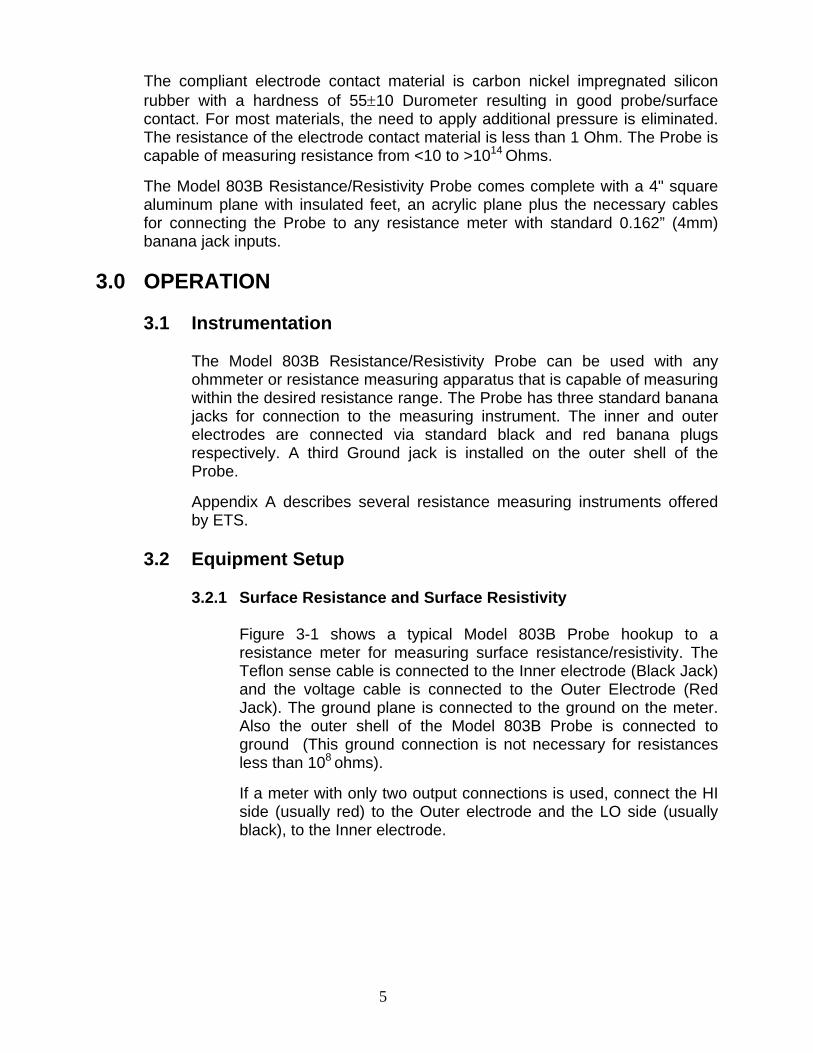
Figure 3-1 shows a typical Model 803B Probe hookup to a resistance meter for measuring surface resistance/resistivity. The Teflon sense cable is connected to the Inner electrode (Black Jack) and the voltage cable is connected to the Outer Electrode (Red Jack). The ground plane is connected to the ground on the meter. Also the outer shell of the Model 803B Probe is connected to ground (This ground connection is not necessary for resistances less than 108 ohms). If a meter with only two output connections is used, connect the HI side (usually red) to the Outer electrode and the LO side (usually black), to the Inner electrode.
6
Resistance Meter
MODEL 803B Test Sample Gnd Plane
Figure 3-1a: 803B Probe/Resistance Meter Hookup for Surface Resistivity Measurement (D257)
Resistance Meter
MODEL 803B Test Sample Insulated (Acrylic) Plane
Figure 3.1b: 803B Probe/ Resistance Meter hookup for Surface Resistance
Measurement (ESDA STM11.11)
SENSE GND OHMS VE SYS GND
7.3x10⁹ Ω
SENSE GND OHMS VE SYS GND
7.3x10⁹ Ω

7
3.2.2 Volume Resistivity
Figure 3-2 shows typical Model 803B Probe hookup to a resistance meter for measuring volume resistance/resistivity. The Teflon sense cable is connected to the Inner electrode (Black Jack) and the voltage cable is connected to the plate (The same plate as is used for the Ground plane for surface resistivity). The Outer electrode (Black Jack) is connected to ground (D257) along with the outer shell of the Probe for measuring the volume resistivity of insulating material. For static dissipative material per ESD DS11.12, the Outer electrode is not connected.
Resistance Meter
MODEL 803B Test Sample Gnd Plane
Figure 3-2: 803B Probe/Resistance Meter Hookup for Volume Resistance/Resistivity Measurement (STM11.12)
3.2.3 Surface and Volume Resistance Calibration Check Fixtures Models 809, 809B and 819
These optional Fixtures are used to check the calibration of the Model 803B Probe. – Refer to Models 809 & 819 Manual.
Figure 3.3: Optional Calibration Check Fixtures
SENSE GND OHMS VE SYS GND
7.3x10⁹ Ω
8
3.3 Measurement of Surface Resistivity, ρs
3.3.1 Material Considerations
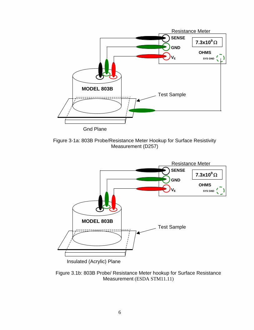
The Model 803B Probe will accurately measure the surface resistance/resistivity of virtually any smooth surface that is greater than 2.5" in diameter. For most film and foam materials the standard 5 pound (2.2kg) Probe weight is sufficient for the electrodes to make total contact with the material surface. For rigid materials, such as table tops, plastics, cardboard, etc., additional force may have to be applied to the Probe to ensure total contact. Microscopically these surfaces are generally not smooth and are uneven, as illustrated in Figure 3-3.
Figure 3-3: Microscopic Electrode/Rigid Surface Contact
In most cases the application of additional pressure will cause the measured resistance reading to decrease. This is a result of both lower contact resistance and the total electrode/surface contact area (greater number of parallel resistance paths).
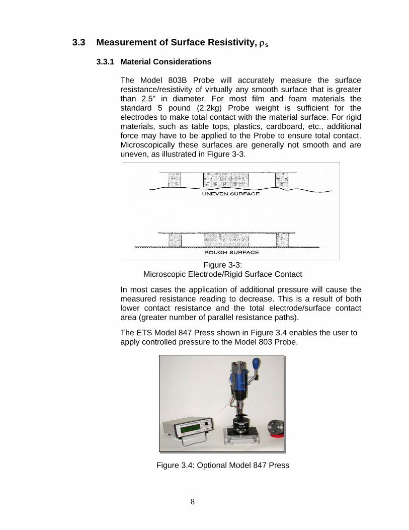
The ETS Model 847 Press shown in Figure 3.4 enables the user to apply controlled pressure to the Model 803 Probe.
Figure 3.4: Optional Model 847 Press

9
Another area that must be considered when attempting to make a surface resistance measurement is the composition of the material being evaluated. The materials defined in ANSI/ASTM D 257 are homogeneous, insulating types. However, in many specifications the materials are nonhomogeneous and relatively conductive. If the material is static dissipative (Rm <1x10¹¹ Ohms) the measurement procedure defined in ESDA STM11.11 should be followed. When measuring the surface resistivity of insulating homogeneous type materials the ground plane is used to guard against stray current paths that may cause measurement errors. Materials that also have relatively low volume resistances cannot be measured using the procedure defined in ASTM D 257. Here, instead of the current path between the two electrodes being only across the top surface it is also through the material to ground. This creates a voltage divider network which results in a surface resistance measurement that will be higher than that obtained without the ground plane. Therefore, the surface resistivity of volume conductive materials cannot be made. The test specimen must be measured on an insulated surface to obtain an accurate indication of its resistance characteristics as specified in ESDA STM11.11.
A similar problem exists with materials that are coated with, or laminated to, a conductive surface. In this case the test voltage is not divided down because the conductive layer is floating, but the conductive layer now becomes a parallel resistance path to the surface being measured. The surface resistance may actually be very high but the measured resistance will be that of the surface resistance path between the two electrodes in parallel with the series combination of the two volume conductive paths and the conductive layer as shown in Figure 3-5.
Figure 3-5: Resistance Path of Laminated Materials
10
For these materials only the net resistance is measured as defined in ESD S11.11. The actual surface resistivity cannot be accurately determined. Another material type is the composite. These materials generally consist of a high resistance resin loaded with conductive fibers or powders. The surface resistivity of these materials is essentially not measurable. What is actually being measured is the net resistance of the series/parallel combination of the conductive component connecting the Inner and Outer electrodes. A common problem that exists with this material is when the conductive component is buried just below the surface the top surface appears as a high resistance. When the test voltage is increased to measure this high resistance, the dielectric of the top surface breaks down and the meter then reads overscale. The above precautions are presented to make the user aware of the complexity in making a surface resistance/resistivity measurement. It is not simply placing a probe onto a surface and reading a meter. With care, many different types of materials can be evaluated, but again, the user is cautioned that the reading obtained may not be the true surface resistivity defined in ANSI/ASTM D 257. ESDA STM11.11 circumvents this problem by defining only the net resistance of the material being measured. Only if the material is truly surface conductive can this resistance measurement be converted to surface resistivity by multiplying the measurement by a factor of 10.
3.3.2 Measuring Considerations 3.3.2.1 Time of Electrification
In the previous section the effect of contact pressure, which actually changes the contact area, on the measurement accuracy was discussed. Another very important consideration that many times is ignored is what is referred to as the "time of electrification". In simple terms the time of electrification is the time for current to flow between the measuring electrodes. All materials have, in basic terms, some capacitance. When measuring low resistances this capacitance is negligible in relation to the resistance of the material. Therefore, the current flow becomes restricted by the resistance of the material only. On the other hand, for high resistance measurements current flow is controlled by both the resistance and capacitance of the material. The resistance does not begin to dominate the measurement until the exponential charging of the measurement system and material capacitance has been completed.

11
The time constant, τ, is expressed as
τ = RC
For total charging, five times constants (5τ) is the accepted norm. Therefore, if a measurement system/material has a total capacitance of 1 picofarad and a total resistance of 1 x 10¹² Ohms, τ = RC = (1 x 10¹²) (1 x 10-12) = 1 second. The total charging time, t = 5 seconds. This is the time of electrification. It is seen that if the capacitance is only a few picofarads the time of electrification can stretch out to many seconds. Figure 3-6 illustrates the time of electrification of an insulating type material.
100% τ = RC 0 1 2 3 4 5
Figure 3-6 Time of Electrification
Resistance that is measured before the full time of electrification has occurred will be less than the actual resistance of the surface. This difference can be several orders of magnitude. ASTM D 257 recommends a time of electrification of 60 seconds, but in many measurements a shorter time may be used or a longer time may be required. Usually for small sample specimens with resistances less than 1010 ohms, an electrification time of 10 to 15 seconds is sufficient or the point at which the resistance measurement stabilizes. On the other hand, with large surfaces, such as table tops, the capacitance is relatively large and 60 seconds may not be long enough. Here, the user can either wait for complete electrification and obtain a true resistance measurement or specify the measurement at the 60 second electrification time point for a relative resistance measurement.
12
In any case, the time of electrification is a critical parameter in the measurement of resistance/resistivity and must be taken into account if meaningful results are to be obtained. ESDA STM11.11 requires the determination of the actual electrification time as part of the measurement procedure.
3.3.2.2 Test Voltage
Certain materials are voltage dependent, that is, the resistance measured at one test voltage will not be the same as that measured with a different voltage. Generally, test voltages of 100, 500 and 1000 Volts are used for very high resistances (109 Ohms and above) while test voltages of 10, 20, 50 and 100 Volts are used for lower resistances in the range of 103 to 1012 Ohms. Some instruments use a single voltage to A STM11.11 specifies a test voltage of 100 Volts for material having surface resistances between 1x10⁶ and 1x10¹¹ Ohms and 10 Volts for resistances between 1x10³ and 1x10⁶ Ohms. Lower voltages or a current source may be used for resistances below 1x10³ Ohms. Another consideration is the contact resistance between the Probe electrodes and the material surface. For certain materials, especially those in the lower resistance range (< 106 ohms), the contact resistance can be a factor. At low ranges a test voltage of 1.5 Volts may used. This low voltage may not be sufficient to breakdown the contact resistance. Hence, a significant difference in measured resistance may be obtained using 1.5 and 10 Volts and even 10 and 100 Volts.
When establishing resistance/resistivity requirements or when comparing resistance/resistivity measurements, the user must specify the test voltage. Failure to do so could result in large measurement differences between different test set-ups.
3.3.2.3 Measurement Procedure
The above information is provided to enable the user to make meaningful and accurate surface resistance/resistivity measurements with the Model 803B Probe. The following is a recommended procedure to be followed when measuring surface resistance/resistivity:

13
1. Determine the type of material being measured. Use the precautions described in the previous sections.
2. Make certain the contact electrodes are clean. The electrodes may be cleaned with Isopropyl alcohol. Allow electrodes to dry before using.
3. Place the Probe firmly on the surface to be measured. If the material to be tested is a film or foam, additional pressure should not be required.
4. Select the appropriate test voltage and resistance range.
5. Observe the meter reading. If it is unstable or the test material is rigid, apply pressure to the Probe. If the meter reading decreases, continue to apply additional pressure until the reading stabilizes.
6. If the meter reading remains stabilized for several seconds, record the reading.
7. If the meter reading continues to slowly increase, wait until it stabilizes or for one minute before taking a reading.
8. Repeat the above measurement procedure at different locations across the material surface.
9. The surface resistivity is 10 times the measured resistance (ρs=10Rm).
Follow the procedure described in ESDA S11.11 for measuring the surface resistance of static dissipative planer material.

14
3.4 Measurement of Volume Resistivity, ρv
The same parameters, electrode contact pressure, time of electrification, excitation voltage and material composition must also be taken into consideration when measuring the volume resistivity, ρv, of materials. The volume resistivity of a material is defined as the resistance through a one cubic centimeter of material. The user is cautioned that a relatively low resistance measured through a very thin film may actually describe a material with a very high volume resistivity. To measure the volume resistance/resistivity of a material the same testing procedure described in Section 3.3.2.3 should be followed. To obtain the volume resistivity, the thickness of the test material must be measured using a metric micrometer or converting the English measurement to metric (1 mil = 2.54 x 10⁻³ cm). The volume resistivity using the Model 803B Probe is then
ρv = 7.1 Rm Ohms - cm t
Follow the procedure described in ESDA STM11.12 for measuring the volume resistance of static dissipative material.
3.5 Other Applications
The Model 803B carbon nickel impregnated electrodes have a very low contact resistance. It is capable of measuring resistances below 10 Ohms. The same measurement procedures and precautions as mentioned above should be observed. The Model 803B Probe can also be used in other applications such as obtaining an indication of the surface resistance to ground. (True surface to ground measurements can only be made using a 2.5” (64mm) diameter, 5 lb (2.2kg) probe such as the ETS Model 850 Surface Resistance Probe.) In this application one side of the ohmmeter is connected to the Inner electrode (Black banana jack) and the other side to ground.
4.0 MAINTENANCE
The Model 803B Resistance/Resistivity Probe is a precision instrument and should be handled as such. The alignment of the Inner and Outer electrodes is critical to ensure total surface contact. The silicon rubber contact material is impregnated with carbon nickel to obtain low contact resistance. The user must ensure that the contact area is clean and free of contaminants prior to making a measurement. Also, the Probe should not be exposed to atmospheres or surfaces that may corrode the carbon nickel particles. If exposure is necessary, the contacts should be cleaned with Isopropyl alcohol immediately after use.
15
When not in use the Probe should be kept on a flat smooth surface such as the test bed. The Probe should never be kept on a sharp or protruding object since this may damage or put a set in the silicon rubber electrodes. If the contact electrodes are damaged or the Probe knocked out of alignment, the unit must be returned to ETS for repair. The Probe does not contain any user replaceable parts. The optional ETS Models 809 and 819 Calibration Check Fixtures, enable the user to verify the integrity and correct alignment of the electrodes prior to use. For measurements below 109 Ohms, standard banana plug-to-banana plug cables may be used. However, for measurements above 109 Ohms a high resistance, such as Teflon, cable must be used for the sense lead. Replacement cables are available from ETS.
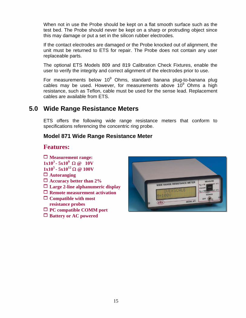
5.0 Wide Range Resistance Meters ETS offers the following wide range resistance meters that conform to specifications referencing the concentric ring probe.
Model 871 Wide Range Resistance Meter
Features:
1 Measurement range: 1x10³ - 5x10⁹ Ω @ 10V 1x10⁵ - 5x10¹² Ω @ 100V 1 Autoranging 1 Accuracy better than 2% 1 Large 2-line alphanumeric display 1 Remote measurement activation 1 Compatible with most resistance probes 1 PC compatible COMM port 1 Battery or AC powered
16
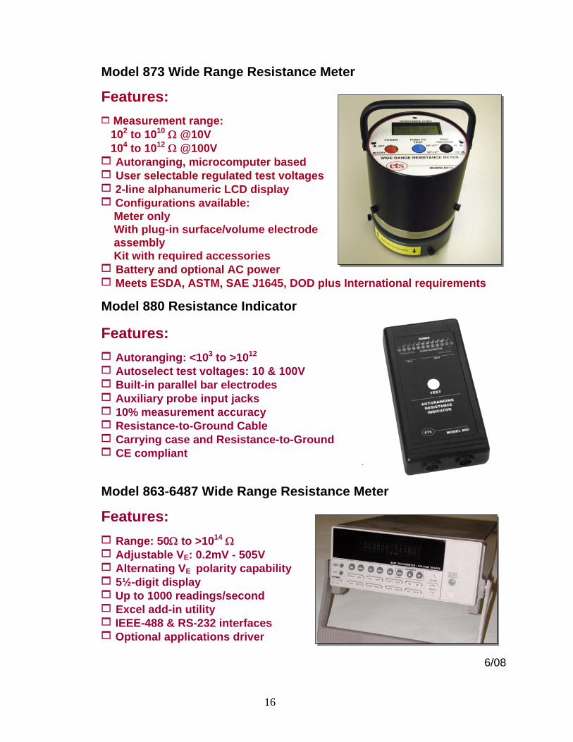
Model 873 Wide Range Resistance Meter
Features:
1 Measurement range: 102 to 1010 Ω @10V 104 to 1012 Ω @100V 1 Autoranging, microcomputer based 1 User selectable regulated test voltages 1 2-line alphanumeric LCD display 1 Configurations available: Meter only With plug-in surface/volume electrode
assembly Kit with required accessories 1 Battery and optional AC power 1 Meets ESDA, ASTM, SAE J1645, DOD plus International requirements
Model 880 Resistance Indicator
Features:
1 Autoranging: <103 to >1012 1 Autoselect test voltages: 10 & 100V 1 Built-in parallel bar electrodes 1 Auxiliary probe input jacks 1 10% measurement accuracy 1 Resistance-to-Ground Cable 1 Carrying case and Resistance-to-Ground 1 CE compliant
Model 863-6487 Wide Range Resistance Meter
Features:
1 Range: 50Ω to >1014 Ω 1 Adjustable VE: 0.2mV - 505V 1 Alternating VE polarity capability 1 5½-digit display 1 Up to 1000 readings/second 1 Excel add-in utility 1 IEEE-488 & RS-232 interfaces 1 Optional applications driver
6/08
17
6.0 WARRANTY
Electro-Tech Systems, Inc. warrants its equipment, its accessories and parts of its manufacture to be and remain free from defects in material and workmanship for a period of one (1) year from the date of invoice, and will, at the discretion of Seller, either replace or repair without charge, F.O.B. Glenside, similar equipment or a similar part to replace any equipment or part of its manufacture which, within the above stated time, is proved to have been defective at the time it was sold. All equipment claimed defective must be returned properly identified to the Seller (or presented to one of its agents for inspection). This warranty only applies to equipment operated in accordance with Seller's operating instructions. Seller's warranty with respect to those parts of the equipment which are purchased from other manufacturers shall be subject only to the manufacturer's warranty. The Seller's liability hereunder is expressly limited to repairing or replacing any parts of the equipment manufactured by the manufacturer and found to have been defective. The Seller shall not be liable for damage resulting or claimed to result from any cause whatsoever. This warranty becomes null and void should the Model 803B Resistance/Resistivity Probe or any part thereof, be abused or modified by the customer of if used in any application other than that for which it was intended. This warranty to replace or repair is the only warranty, either expressed of implied or provided by law, and is in lieu of all other warranties and the Seller denies any other promise, guarantee, or warranty with respect to the equipment or accessories and, in particular, as to its or their suitability for the purposes of the buyer or its or their performance, either quantitatively or qualitatively or as to the products which it may produce and the buyer is expected to expressly waive rights to any warranty other than that stated herein.
ETS must be notified before any equipment is returned for repair. ETS will issue an RMA (Return Material Authorization) number for return of said equipment. Equipment should be shipped in the original packaging. If this is not possible, the equipment should be packed in a sufficiently large box of double wall construction with substantial packing around all sides. A description of the problem along with the contact name and telephone number must be included in formal paperwork and enclosed with the instrument.
Electro-Tech Systems, Inc. will not assume responsibility for additional cost of repair due to damage incurred during shipment as a result of poor packaging.