802.3bp 1000base-t1 auto-negotiation on single twisted...
TRANSCRIPT

Auto-Negotiation on Single Twisted Pair Proposal Rev 0.4
1 October 28, 2014
802.3bp 1000BASE-T1 Auto-Negotiation on Single Twisted Pair
Baseline Text Proposal

Auto-Negotiation on Single Twisted Pair Proposal Rev 0.4
2 October 28, 2014
888 Physical Layer Link Signaling for Auto-Negotiation on Single Twisted Pair ......................................................................... 3
888.1 Overview ....................................................................................................................................................................... 3 888.1.1 Scope .................................................................................................................................................................... 3 888.1.2 Relationship to the ISO/IEC Open Systems Interconnection (OSI) reference model ............................................. 4
888.2 Functional specifications ............................................................................................................................................... 5 888.2.1 Transmit function requirements ............................................................................................................................. 5
888.2.1.1 DME transmission ............................................................................................................................................. 5 888.2.1.1.1 DME page encoding ................................................................................................................................... 5 888.2.1.1.2 DME page timing ........................................................................................................................................ 7
888.2.1.1.2.1 Sync Header and Manchester violation delimiter ......................................................................................... 8 888.2.1.2 Link codeword encoding ................................................................................................................................... 8
888.2.1.2.1 Selector Field ............................................................................................................................................. 9 888.2.1.2.2 Echoed Nonce Field ................................................................................................................................... 9 888.2.1.2.3 Transmitted Nonce Field ............................................................................................................................ 9 888.2.1.2.4 Technology Ability Field ............................................................................................................................. 9 888.2.1.2.5 Force Master/Slave .................................................................................................................................. 10 888.2.1.2.6 Pause Ability ............................................................................................................................................ 10 888.2.1.2.7 Remote Fault ............................................................................................................................................ 11 888.2.1.2.8 Acknowledge ............................................................................................................................................ 11 888.2.1.2.9 Next Page ................................................................................................................................................ 11
888.2.1.3 Transmit Switch function ................................................................................................................................. 11 888.2.2 Receive function requirements ............................................................................................................................ 12
888.2.2.1 DME page reception ....................................................................................................................................... 12 888.2.2.2 Receive Switch function .................................................................................................................................. 12 888.2.2.3 Link codeword matching ................................................................................................................................. 12
888.2.3 Half Duplex function requirements ....................................................................................................................... 12 888.2.4 Arbitration function requirements ......................................................................................................................... 12
888.2.4.1 Renegotiation function .................................................................................................................................... 12 888.2.4.2 Priority Resolution function ............................................................................................................................. 13 888.2.4.3 Next Page function ......................................................................................................................................... 13
888.2.4.3.1 Next page encodings ............................................................................................................................... 14 888.2.4.3.2 Use of Next Pages ................................................................................................................................... 14
888.3 Management register requirements ............................................................................................................................ 15 888.4 Technology-Dependent interface ................................................................................................................................ 15
888.4.1 AN_LINK.indication .............................................................................................................................................. 15 888.4.1.1 Semantics of the service primitive .................................................................................................................. 15 888.4.1.2 When generated ............................................................................................................................................. 15 888.4.1.3 Effect of receipt ............................................................................................................................................... 15
888.5 State diagrams and variable definitions ...................................................................................................................... 16 888.5.1 State diagram variables ....................................................................................................................................... 16 888.5.2 State diagram timers ............................................................................................................................................ 23 888.5.3 State diagram counters ........................................................................................................................................ 24 888.5.4 Function ............................................................................................................................................................... 24 888.5.5 State diagrams .................................................................................................................................................... 25
888.6 Electrical specifications ............................................................................................................................................... 29 888.7 Protocol implementation conformance statement (PICS) proforma for Clause 888, Auto-Negotiation on Single Twisted Pair .............................................................................................................................................................................. 29
Annex 888A .................................................................................................................................................................................. 29 Annex 888B .................................................................................................................................................................................. 30
888B.1 Selector field value ....................................................................................................................................................... 30 888B.2 Technology Ability Field bit assignments ...................................................................................................................... 30 888B.3 Priority Resolution ......................................................................................................................................................... 30 888B.4 Message Page transmission convention....................................................................................................................... 30
Annex 888C .................................................................................................................................................................................. 31 888C.1 Message code 0—Auto-Negotiation reserved code 1 .................................................................................................. 31 888C.2 Message code 1—Null Message code ......................................................................................................................... 31

Auto-Negotiation on Single Twisted Pair Proposal Rev 0.4
3 October 28, 2014
(Red are editing comments, highlighted yellow are TBD, and highlighted red needs attention) 888 Physical Layer Link Signaling for Auto-Negotiation on Single Twisted Pair 888.1 Overview 888.1.1 Scope Clause 888 describes the single twisted pair Auto-Negotiation function that allows a device to advertise enhanced modes of operation it possesses to a device at the remote end of a link segment and to detect corresponding enhanced operational modes that the other device may be advertising. The normative definitions for all extensions to single twisted pair Auto-Negotiation and all related register assignments for this standard are documented in Annex 888A. The objective of the single twisted pair Auto-Negotiation function is to provide the means to exchange information between two devices that share a link segment and to automatically configure both devices to take maximum advantage of their abilities. It has the additional objective of providing a common synchronization time between two devices prior to link training. Single twisted pair Auto-Negotiation is performed using differential Manchester encoding (DME) pages. DME provides a DC balanced signal. DME does not add packet or upper layer overhead to the network devices. DME is transferred in a half-duplex manner over the single twisted pair. Single twisted pair Auto-Negotiation does not test the link segment characteristics. The function allows the devices at both ends of a link segment to advertise abilities, acknowledge receipt and understanding of the common mode(s) of operation that both devices share, and to reject the use of operational modes that are not shared by both devices. Where more than one common mode exists between the two devices, a mechanism is provided to allow the devices to resolve to a single mode of operation using a predetermined priority resolution function. The single twisted pair Auto-Negotiation function allows the devices to switch between the various operational modes in an ordered fashion, and allows management to select a specific operational mode.
Figure 888-1 - High-level model

Auto-Negotiation on Single Twisted Pair Proposal Rev 0.4
4 October 28, 2014
888.1.2 Relationship to the ISO/IEC Open Systems Interconnection (OSI) reference model The single twisted pair Auto-Negotiation function is provided at the Physical Layer of the ISO/IEC OSI reference model as shown in Figure 888-2. A device that supports multiple modes of operation may advertise its capabilities using the single twisted pair Auto-Negotiation function. The actual transfer of information is observed only at the MDI
MDI = MEDIUM DEPENDENT INTERFACE MII = MEDIA INDEPENDENT INTERFACE AUTONEG = AUTO-NEGOTIATION PCS = PHYSICAL CODING SUBLAYER PMA = PHYSICAL MEDIUM ATTACHMENT PHY = PHYSICAL LAYER DEVICE PMD = PHYSICAL MEDIUM DEPENDENT * MII is optional ** PMD is not specified for 1000BASE-T1 *** PCS communicates with the AUTONEG sublayer through the PCS service interface messages AN_LINK.indication
Figure 888-2 – Location of Auto-Negotiation function within the ISO/IEC OSI reference model

Auto-Negotiation on Single Twisted Pair Proposal Rev 0.4
5 October 28, 2014
888.2 Functional specifications The single twisted pair Auto-Negotiation function provides a mechanism to control connection of a single MDI to a single PHY type, where more than one PHY type may exist. A management interface provides control and status of single twisted pair Auto-Negotiation, but the presence of a management agent is not required. The single twisted pair Auto-Negotiation function shall provide the following:
a) Auto-Negotiation transmit b) Auto-Negotiation receive c) Auto-Negotiation half duplex d) Auto-Negotiation arbitration
These functions shall comply with the state diagrams from Figure 888-11 through Figure 888-14. The single twisted pair Auto-Negotiation functions shall interact with the technology-dependent PHYs through the Technology-Dependent interface (see 888.4). 888.2.1 Transmit function requirements The Transmit function provides the ability to transmit pages. The first pages exchanged by the local device and its link partner after Power-On, link restart, or renegotiation contain the base link codeword defined in Figure 888-8 - Link codeword Base Page. The local device may modify the link codeword to disable an ability it possesses, but will not transmit an ability it does not possess. This makes possible the distinction between local abilities and advertised abilities so that multi-ability devices may Auto-Negotiate to a mode lower in priority than the highest common ability. 888.2.1.1 DME transmission Auto-Negotiation’s method of communication builds upon the encoding mechanism known as differential Manchester encoding (DME). The DME page encodes the data that is used to control the Auto-Negotiation function. DME pages shall not be transmitted when Auto-Negotiation is complete and the highest common denominator PHY has been enabled. 888.2.1.1.1 DME page encoding A DME page carries a 48-bit Auto-Negotiation page. It consists of TBD (Tentatively 164 = 32 + 128 + 6) evenly spaced transition positions that contain a starting sync header, the 48-bit page, 16-bit CRC, and an ending Manchester violation delimiter. The odd-numbered transition positions represent clock information. The even numbered transition positions represent data information. DME pages are alternately transmitted between the two devices with quiet period separating the DME pages. The first TBD (Tentatively 32) transition positions contain the starting sync header, which marks the beginning of the page. The starting sync header contains a transition from quiet to active at position 1 followed by transitions at positions TBD (Tentatively 2, 4, 5, 6, 8, 9, 13, 14, 15, 16, 17, 20, 21, 23, 26, 31, 32) and no transitions at the remaining positions. The final 6 transition positions contain the ending Manchester violation delimiter, which marks the end of the page. The ending Manchester violation contains transitions at positions TBD (Tentatively 153 and 156) and no transitions at the remaining positions. Position TBD (tentatively 159) contains a transition from active to quiet. The starting sync header and ending Manchester violation delimiter are the only places where three or more intervals occur between transitions. This allows the receiver to obtain page synchronization. Each of the remaining 64 odd-numbered transition positions between the starting and ending delimiters shall contain a transition. The remaining 64 even-numbered transition positions shall represent data information as follows: — A transition present in an even-numbered transition position represents a logical one — A transition absent from an even-numbered transition position represents a logical zero

Auto-Negotiation on Single Twisted Pair Proposal Rev 0.4
6 October 28, 2014
The first 48 of these positions shall carry the data of the Auto-Negotiation page. The final 16 positions carry the 16 bit CRC. The CRC16 polynomial is x16 + x15 + x2 + 1. The CRC16 shall produce the same result as the implementation shown in Figure 888-3. The 16 delay elements S0,..., S15, shall be initialized to zero. Afterwards the 48 data bits are used to compute the CRC16 with the switch connected (setting CRCgen). After all the 48 bits have been processed, the switch is disconnected (setting CRCout) and the 16 values stored in the delay elements are transmitted in the order illustrated, first S15, followed by S14, and so on, until the final value S0.
Figure 888-3 - CRC16
(From figure 55-27. Oct5 through Oct14 should be replaced with 48 bit data) The polarity at position 0 is determined the pseudo-random generator as shown in Figure 888-4. If the bit is a 1 then the starting polarity is positive, otherwise the starting polarity is negative.
Figure 888-4 - DME page starting polarity randomizer
The counter shall increment once per DME page. The purpose of randomizing the starting polarity is to remove the spectral peaks that would otherwise occur when sending the same DME page repeatedly. Randomly choosing the starting polarity results in randomly inverting or not inverting the encoded page so that repetitions of the same page no longer produce a periodic signal. Clock transition positions are differentiated from data transition positions by the spacing between them, as shown in Figure 888-5 and enumerated in Table 888-1. The encoding of data using DME bits in a DME page is illustrated in Figure 888-5.

Auto-Negotiation on Single Twisted Pair Proposal Rev 0.4
7 October 28, 2014
Figure 888-5 - Data bit encoding within DME pages (From figure 73-3. ) 888.2.1.1.2 DME page timing The timing parameters for DME pages shall be followed as in Table 888-1. The transition positions within a DME page are spaced with a period of T1. T2 is the separation between clock transitions. T3 is the time from a clock transition to a data transition representing a one. The period, T1, shall be 30.0 ns ± 0.01%. Transitions shall occur within ± 0.8 ns of their ideal positions. T5 specifies the duration of a DME page. The minimum number of transitions and maximum number of transitions in a page is represented by T4a. T4b indicates that the start of a DME page begins with a transition from 0 to +/-1 and the end of the DME page is a transition from +/-1 to 0. Table 888-1 summarizes the timing parameters. The transition timing parameters are illustrated in Figure 888-6 and Figure 888-7.
Table 888-1 - DME page timing summary
Parameter Min Typ Max Units
T1 Transmit position spacing (period) 30.997 30 30.003 ns
T2 Clock transition to clock transition 59 60 61 ns
T3 Clock transition to data transition (data = 1) 29 30 31 ns
T4a +1 to ‐1 or ‐1 to +1 transitions in a DME page 83 ‐ 147 ‐
T4b 0 to +/1 or +/‐1 to 0 transitions in a DME page 2 2 2 ‐
T5 DME page width 4735 4740 4745 ns
T6 DME Manchester violation delimiter width TBD TBD TBD ns

Auto-Negotiation on Single Twisted Pair Proposal Rev 0.4
8 October 28, 2014
Figure 888-6 - DME page transition timing
(From figure 73-4. ) 888.2.1.1.2.1 Sync Header and Manchester violation delimiter The page is preceded by a unique sync header consisting of a 32 x T3 PRBS sequence that includes multiple DME transition violations. For a sync header starting with a 0 to +1 transition, the bit sequence is: +1,-1,-1,+1,-1,+1,+1,-1,+1,+1,+1,+1,-1,+1,-1,+1,-1,-1,-1,+1,-1,-1,+1,+1,+1,-1,-1,-1, -1,-1,+1,-1. The page end is followed by a DME violation delimiter. A violation is signaled as shown in Figure 888-7. NOTE- the sync header may begin with a 0 to +1 or 0 to -1 transition depending upon the DME page starting polarity randomizer.
Figure 888-7 - Manchester violation
888.2.1.2 Link codeword encoding The base link codeword (Base Page) transmitted within a DME page shall convey the encoding shown in Figure 888-8. The Auto-Negotiation function supports additional pages using the Next Page function. Encoding for the link codeword(s) used in the Next Page exchange are defined in 888.2.4.3. In a DME page, D0 shall be the first bit transmitted.
Figure 888-8 - Link codeword Base Page D[4:0] contains the Selector Field. D[9:5] contains the Echoed Nonce field. D[11:10] contains capability bits to advertise capabilities not related to the PHY. C[1:0] is used to advertise pause capability. D[12] is the force Master/Slave bit (see TBD). D[15:13] contains the RF, Ack, and NP bits. These bits shall function as specified in 28.2.1.2. D[20:16] contains the Transmitted Nonce field. D[47:21] contains the Technology Ability Field.

Auto-Negotiation on Single Twisted Pair Proposal Rev 0.4
9 October 28, 2014
888.2.1.2.1 Selector Field Selector Field (S[4:0]) is a five-bit wide field, encoding 32 possible messages. Selector Field encoding definitions are shown in Annex 28A. Combinations not specified are reserved for future use. Reserved combinations of the Selector Field shall not be transmitted. The Selector Field for IEEE Std 802.3 is shown in Table 888-2.
Table 888-2 - Selector Field Encoding
(From table 73-3. ) 888.2.1.2.2 Echoed Nonce Field Echoed Nonce Field (E[4:0]) is a 5-bit wide field containing the nonce received from the link partner. If the device has not received a DME page with good CRC16, the bits in this field shall contain logical zeros. If the device has received a DME page with good CRC16, the bits in this field shall contain the value received in the Transmitted Nonce Field from the link partner at the same time as the Acknowledge bit is set. 888.2.1.2.3 Transmitted Nonce Field Transmitted Nonce Field (T[4:0]) is a 5-bit wide field whose lower 4 bits contains a random or pseudo-random number. A new value shall be generated for each entry to the Ability Detect state. The method of generating the nonce is left to the implementer. The lower 4 bits of the transmitted nonce should have a uniform distribution in the range from 0 to 24
– 1. The method used to generate the value should be designed to minimize correlation to the values generated by other devices. Bit T[4] should be set to 1 if the device prefers or is forced to be master and 0 if the device prefers or is forced to be slave. If the device has received a DME page with good CRC16 and the link partner has a Transmitted Nonce Field (T[4:0]) that matches the devices generated T[4:0], the device must invert its T[0] bit and regenerate a new random value for T[3:1] and use that as its new T[4:0] value. Since the DME pages are exchanged in a half-duplex manner, it is possible to swap to a new T[4:0] value prior to transmitting the DME page. One device will always see a DME page with good CRC16 before the other device hence this swapping will guarantee that nonce_match will never be true. 888.2.1.2.4 Technology Ability Field Technology Ability Field (A[26:0]) is a 27-bit wide field containing information indicating supported technologies specific to the selector field value when used with the single twisted pair Auto-Negotiation Ethernet. These bits are mapped to individual technologies such that abilities are advertised in parallel for a single selector field value. The Technology Ability Field encoding for the IEEE 802.3 selector with single twisted pair Auto-Negotiation Ethernet is described in Annex 888B.2 Technology Ability Field bit assignments. Multiple technologies may be advertised in the link codeword. A device shall support the data service ability for a technology it advertises. It is the responsibility of the Arbitration function to determine the common mode of operation shared by a link partner and to resolve multiple common modes.
Auto-Negotiation on Single Twisted Pair Proposal Rev 0.4
10 October 28, 2014
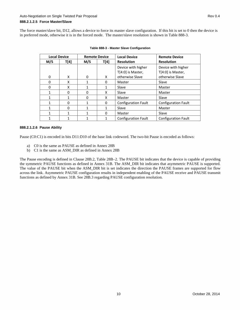
888.2.1.2.5 Force Master/Slave The force master/slave bit, D12, allows a device to force its master slave configuration. If this bit is set to 0 then the device is in preferred mode, otherwise it is in the forced mode. The master/slave resolution is shown in Table 888-3.
Table 888-3 - Master Slave Configuration
Local Device Remote Device Local Device Resolution
Remote Device Resolution M/S T[4] M/S T[4]
0 X 0 X
Device with higher T[4:0] is Master, otherwise Slave
Device with higher T[4:0] is Master, otherwise Slave
0 X 1 0 Master Slave
0 X 1 1 Slave Master
1 0 0 X Slave Master
1 1 0 X Master Slave
1 0 1 0 Configuration Fault Configuration Fault
1 0 1 1 Slave Master
1 1 1 0 Master Slave
1 1 1 1 Configuration Fault Configuration Fault 888.2.1.2.6 Pause Ability Pause (C0:C1) is encoded in bits D11:D10 of the base link codeword. The two-bit Pause is encoded as follows:
a) C0 is the same as PAUSE as defined in Annex 28B b) C1 is the same as ASM_DIR as defined in Annex 28B
The Pause encoding is defined in Clause 28B.2, Table 28B–2. The PAUSE bit indicates that the device is capable of providing the symmetric PAUSE functions as defined in Annex 31B. The ASM_DIR bit indicates that asymmetric PAUSE is supported. The value of the PAUSE bit when the ASM_DIR bit is set indicates the direction the PAUSE frames are supported for flow across the link. Asymmetric PAUSE configuration results in independent enabling of the PAUSE receive and PAUSE transmit functions as defined by Annex 31B. See 28B.3 regarding PAUSE configuration resolution.

Auto-Negotiation on Single Twisted Pair Proposal Rev 0.4
11 October 28, 2014
888.2.1.2.7 Remote Fault Remote Fault (RF) is encoded in bit D13 of the base link codeword. The default value is logical zero. The Remote Fault bit provides a standard transport mechanism for the transmission of simple fault information. When the RF bit in the AN advertisement register (Register 7.16.13) is set to logical one, the RF bit in the transmitted base link codeword is set to logical one. When the RF bit in the received base link codeword is set to logical one, the Remote Fault bit in the AN LP Base Page ability register (Register 7.19.13) will be set to logical one, if the management function is present. 888.2.1.2.8 Acknowledge Acknowledge (Ack) is used by the Auto-Negotiation function to indicate that a device has successfully received its link partner’s link codeword. The Acknowledge Bit is encoded in bit D14 of link codeword. If no Next Page information is to be sent, this bit shall be set to logical one in the link codeword after the reception of at least one DME pages with correct CRC. If Next Page information is to be sent, this bit shall be set to logical one after the device has successfully received at least one DME page with correct CRC, and will remain set until the Next Page information has been loaded into the AN XNP transmit register (Registers 7.22, 7.23, 7.24). In order to save the current received link codeword, it must be read from the AN LP XNP ability register (Register 7.25, 7.26, 7.27) before the Next Page of transmit information is loaded into the AN XNP transmit register. After the COMPLETE ACKNOWLEDGE state has been entered, the link codeword will be transmitted at least three times. 888.2.1.2.9 Next Page Next Page (NP) is encoded in bit D15 of link codeword. Support of Next Pages is mandatory. If the device does not have any Next Pages to send, the NP bit shall be set to logical zero. If a device wishes to engage in Next Page exchange, it shall set the NP bit to logical one. If a device has no Next Pages to send and its link partner has set the NP bit to logical one, it shall transmit Next Pages with Null message codes and the NP bit set to logical zero while its link partner transmits valid Next Pages. Next page exchanges will occur if either the device or its link partner sets the Next Page bit to logical one. The Next Page function is defined in 888.2.4.3. 888.2.1.3 Transmit Switch function The Transmit Switch function shall enable the transmit path from a single technology-dependent PHY to the MDI once a highest common denominator choice has been made and Auto-Negotiation has completed. During Auto-Negotiation, the Transmit Switch function shall connect only the DME page generator controlled by the Transmit State Diagram to the MDI. When a PHY is connected to the MDI through the Transmit Switch function, the signals at the MDI shall conform to all of the PHY’s specifications.

Auto-Negotiation on Single Twisted Pair Proposal Rev 0.4
12 October 28, 2014
888.2.2 Receive function requirements The Receive function detects the DME page sequence, decodes the information contained within, and stores the data in rx_link_code_word[64:1]. The receive function incorporates a receive switch to control connection to the various PMAs. 888.2.2.1 DME page reception To be able to detect the DME bits, the receiver should have the capability to receive DME signals sent with the electrical specifications of the PHY. The DME transmit signal level and receive sensitivity are specified in 888.6. 888.2.2.2 Receive Switch function The Receive Switch function shall enable the receive path from the MDI to a single technology-dependent PHY once a highest common denominator choice has been made and Auto-Negotiation has completed. During Auto-Negotiation, the Receive Switch function shall connect the DME page receiver controlled by the Receive state diagram to the MDI and the Receive Switch function shall also connect the appropriate receivers to the MDI. 888.2.2.3 Link codeword matching The Receive function shall generate ability_match, acknowledge_match, and consistency_match variables as defined in Arbitration state diagram Figure 888-14. 888.2.3 Half Duplex function requirements The Half Duplex function is defined by Figure 888-13 and ensures that only one of the link partners is transmitting a DME page at each step during the DME page exchange process. The Half Duplex function uses a blind timer to ensure that the receiver ignores signals reflected from the channel following the end of the device's transmitted DME page. A silent timer is used to ensure that the device does not begin transmitting the DME page until after the link partner has exited from the blind timer. The Half Duplex backoff timer resolves the half duplex collisions by using a random wait time listen for a DME page to arrive from the link partner before the local device transmits a DME page. 888.2.4 Arbitration function requirements The Arbitration function is defined by Figure 888-14 and ensures proper sequencing of the Auto-Negotiation function using the Transmit function, Receive function, and Half-Duplex function. The Arbitration function enables the Transmit function to advertise and acknowledge abilities. Upon indication of acknowledgement, the Arbitration function determines the highest common denominator using the priority resolution function and enables the appropriate technology-dependent PHY via the Technology-Dependent interface (see 888.4). 888.2.4.1 Renegotiation function A renegotiation request from any entity, such as a management agent, shall cause the Arbitration function to disable all technology-dependent PHYs and halt any transmit data and link transition activity until the break_link_timer expires. Consequently, the link partner will go into link fail and normal Auto-Negotiation resumes. The local device shall resume Auto-Negotiation after the break_link_timer has expired by issuing DME pages with the Base Page valid in tx_link_code_word[64:1]. Once Auto-Negotiation has completed, renegotiation will take place if the Highest Common Denominator technology that receives link_control=ENABLE returns link_status=FAIL. To allow the PHY an opportunity to determine link integrity using its own link integrity test function, the link_fail_inhibit_timer qualifies the link_status=FAIL indication such that renegotiation takes place if the link_fail_inhibit_timer has expired and the PHY still indicates link_status=FAIL.

Auto-Negotiation on Single Twisted Pair Proposal Rev 0.4
13 October 28, 2014
888.2.4.2 Priority Resolution function Since a local device and a link partner may have multiple common abilities, a mechanism to resolve which mode to configure is required. The mechanism used by Auto-Negotiation is a Priority Resolution function that predefines the hierarchy of supported technologies. The single PHY enabled to connect to the MDI by Auto-Negotiation shall be the technology corresponding to the bit in the Technology Ability Field common to the local device and link partner that has the highest priority as defined in Annex 888B.3 Priority Resolution (listed from highest priority to lowest priority). The common technology is referred to as the highest common denominator, or HCD, technology. If the local device receives a Technology Ability Field with a bit set that is reserved, the local device shall ignore that bit for priority resolution. Determination of the HCD technology occurs on entrance to the AN GOOD CHECK state. In the event that there is no common technology, HCD shall have a value of “NULL”, indicating that no PHY receives link_control=ENABLE and link_status[HCD]=FAIL. 888.2.4.3 Next Page function The Next Page function uses the Auto-Negotiation arbitration mechanisms to allow exchange of Next Pages of information, which may follow the transmission and acknowledgment procedures used for the base link codeword. The Next Page has both Message code field and Unformatted code fields. A dual acknowledgment system is used. Acknowledge (Ack) is used to acknowledge receipt of the information; Acknowledge 2 (Ack2) is used to indicate that the receiver is able to act on the information (or perform the task) defined in the message. The Toggle bit is used to ensure proper synchronization between the local device and the link partner. Next page exchange occurs after the base link codewords have been exchanged if either end of the link segment set the Next Page bit to logical one indicating that it had at least one Next Page to send. Next page exchange consists of using the normal Auto-Negotiation arbitration process to send Next Page messages. The Next Page contains two message encodings. The message encodings are defined as follows: message code, which contain predefined 11-bit codes, and unformatted code contains 32 bit codes. Multiple Next Pages with appropriate message codes and unformatted codes can be transmitted to send extended messages. Each series of Next Pages shall have a Message code that defines how the Unformatted codes will be interpreted. Any number of Next Pages may be sent in any order; however, it is recommended that the total number of Next Pages sent be kept small to minimize the link startup time. Next page transmission ends when both ends of a link segment set their Next Page bits to logical zero, indicating that neither has anything additional to transmit. It is possible for one device to have more pages to transmit than the other device. Once a device has completed transmission of its Next Page information, it shall transmit Next Pages with Null message codes and the NP bit set to logical zero while its link partner continues to transmit valid Next Pages. An Auto-Negotiation able device shall recognize reception of Message Pages with Null message codes as the end of its link partner’s Next Page information.

Auto-Negotiation on Single Twisted Pair Proposal Rev 0.4
14 October 28, 2014
888.2.4.3.1 Next page encodings The Next Page shall use the encoding shown in Figure 888-9 and Figure 888-10 for the NP, Ack, MP, Ack2, and T bits. These bits shall function as specified in 28.2.3.4. There are two types of Next Page encodings - message and unformatted. For message Next Pages, the MP bit shall be set to logical one, the 11-bit field D[10:0] shall be encoded as a Message Code Field and D[47:16] shall be encoded as Unformatted Code Field. For Unformatted Next Pages, the MP bit shall be set to logical zero; D[10:0] and D[47:16] shall be encoded as the Unformatted Code Field.
Figure 888-9 - Message Next Page
Figure 888-10 - Unformatted Next Page 888.2.4.3.2 Use of Next Pages Next page exchange will commence after the Base Page exchange if either device requests it by setting the NP bit to logical one. Next page exchange shall continue until neither device on a link has more pages to transmit as indicated by the NP bit. A Next Page with a Null Message Code Field value shall be sent if the device has no other information to transmit. A message code can carry either a specific message or information that defines how the corresponding unformatted codes should be interpreted.

Auto-Negotiation on Single Twisted Pair Proposal Rev 0.4
15 October 28, 2014
888.3 Management register requirements The management interface is used to communicate Auto-Negotiation information to the management entity. MMD7 of the Clause 45 Management Data Input/Output (MDIO) interface shall be provided as the logical interface to access the device registers for Auto-Negotiation and other management purposes. The Clause 45 MDIO electrical interface is optional. Where no physical embodiment of the MDIO exists, provision of an equivalent mechanism to access the registers is recommended. Table 888-4 provides the mapping of state diagram variables to management registers.
Table 888-4 - State diagram variable to Single Twisted Pair Auto-Negotiation register mapping
State diagram variable Description
mr_adv_ability[48:1] {7.18.15:0, 7.17.15:0, 7.16.15:0} AN advertisement registers
mr_autoneg_complete 7.1.5 Auto-Negotiation Complete
mr_autoneg_enable 7.0.12 Auto-Negotiation Enable
mr_lp_adv_ability[48:1]
For Base Page: {7.21.15:0, 7.20.15:0, 7.19.15:0} AN LP Base Page ability registers For Next Page(s): {7.27.15:0, 7.26.15:0, 7.25.15:0} AN LP XNP ability registers
mr_lp_autoneg_able 7.1.0 LP Auto-Negotiation Able
mr_main_reset 7.0.15 Reset
mr_next_page_loaded Set on write to AN XNP Transmit registers; cleared by Arbitration state diagram
mr_np_tx[48:1] {7.24.15:0, 7.23.15:0, 7.22.15:0} AN XNP Transmit registers
mr_page_rx 7.1.6 Page Received
mr_restart_negotiation 7.0.9 Auto-Negotiation Restart
set to 1 7.1.3 Auto-Negotiation Ability 888.4 Technology-Dependent interface The Technology-Dependent interface is the communication mechanism between each technology’s PCS and the Auto-Negotiation function. Auto-Negotiation can support multiple technologies, all of which need not be implemented in a given device. Each of these technologies may utilize its own technology-dependent link integrity test function. 888.4.1 AN_LINK.indication This primitive is generated by the PCS to indicate the status of the underlying medium. The purpose of this primitive is to give the Auto-Negotiation function a means of determining the validity of received code elements. 888.4.1.1 Semantics of the service primitive AN_LINK.indication(link_status) The link_status parameter shall assume one of two values: OK or FAIL, indicating whether the underlying receive channel is intact and enabled (OK) or not intact (FAIL). 888.4.1.2 When generated A technology-dependent PCS generates this primitive to indicate a change in the value of link_status. 888.4.1.3 Effect of receipt The effect of receipt of this primitive shall be governed by the state diagram of Figure 888-14.

Auto-Negotiation on Single Twisted Pair Proposal Rev 0.4
16 October 28, 2014
888.5 State diagrams and variable definitions The notation used in state diagrams follows the conventions in Clause 28.Variables in a state diagram with default values evaluate to the variable default in each state where the variable value is not explicitly set. Auto-Negotiation shall implement the Transmit state diagram, Receive state diagram, Half Duplex state diagram, and Arbitration state diagram. Additional requirements to these state diagrams are made in the respective functional requirements sections. Options to these state diagrams clearly stated as such in the functional requirements sections or state diagrams shall be allowed. In the case of any ambiguity between stated requirements and the state diagrams, the state diagrams shall take precedence. 888.5.1 State diagram variables A variable with “_[x]” appended to the end of the variable name indicates a variable or set of variables as defined by “x”. “x” may be as follows:
all; represents all specific technology-dependent PMAs supported in the local device.
HCD; represents the single technology-dependent PMA chosen by Auto-Negotiation as the highest common denominator technology through the Priority Resolution.
notHCD; represents all technology-dependent PMAs not chosen by Auto-Negotiation as the highest common
denominator technology through the Priority Resolution.
Variables with [48:1] appended to the end of the variable name indicate arrays that can be directly mapped to 48-bit registers. For these variables, “[x]” indexes an element or set of elements in the array, where “[x]” may be as follows:
a) Any integer b) Any range of integers c) Any variable that takes on integer values d) NP; represents the index of the Next Page bit e) ACK; represents the index of the Acknowledge bit f) RF; represents the index of the Remote Fault bit
Variables of the form “mr_x”, where x is a label, comprise a management interface that is intended to be connected to the Management function. However, an implementation-specific management interface may provide the control and status function of these bits ability_match
Indicates that at least one link codewords with good CRC16 was received.
Values: false; at least one link codeword with good CRC16 has not been received (default). true; at least one link codeword with good CRC16 has been received.
NOTE—This variable is set by this variable definition; it is not set explicitly in the state diagrams.
ability_match_word [48:1]
A 48-bit array that is loaded upon transition to Acknowledge Detect state with the value of the link codeword that caused ability_match = true for that transition. For each element in the array transmitted. Values: zero; data bit is logical zero.
one; data bit is logical one.
NOTE—This variable is set by this variable definition; it is not set explicitly in the state diagrams.

Auto-Negotiation on Single Twisted Pair Proposal Rev 0.4
17 October 28, 2014
ack_finished Status indicating that the final remaining_ack_cnt link codewords with the Ack bit set have been transmitted. Values: false; more link codewords with the Ack bit set to logical one must be transmitted.
true; all remaining link codewords with the Ack bit set to logical one have been transmitted. ack_nonce_match
Indicates whether the echoed nonce received from the link partner matches the transmitted nonce field sent by the local device. The echoed nonce value from the DME page that caused acknowledge_match to be set is used for this test.
Values: false; link partner echoed nonce does not equal local device transmitted nonce.
true; link partner echoed nonce equals local device transmitted nonce. acknowledge_match
Indicates that at least one link codeword with the Acknowledge bit set and with good CRC16 was received. The link codeword that initially set the ability_match variable should not be used to set this variable.
Values: false; at least one link codeword with the Acknowledge bit set and with good CRC16 has not been
received (default). true; at least one link codeword with the Acknowledge bit set and with good CRC16 has been received.
NOTE—This variable is set by this variable definition; it is not set explicitly in the state diagrams.
an_link_good
Indicates that Auto-Negotiation has completed. Values: false; negotiation is in progress (default).
true; negotiation is complete, forcing the Transmit and Receive functions to IDLE.
an_receive_idle Indicates that the Receive state diagram is in the IDLE state.
Values: false; the Receive state diagram is not in the IDLE state (default).
true; the Receive state diagram is in the IDLE state. base_page
Status indicating that the page currently being transmitted by Auto-Negotiation is the initial link codeword encoding used to communicate the device’s abilities.
Values: false; a page other than base link codeword is being transmitted.
true; the base link codeword is being transmitted. code_sel
A Boolean random or pseudo-random value uniformly distributed. A new value is generated each time the variable code_sel is used.
Values: zero; a zero has been assigned.
one; a one has been assigned. complete_ack
Controls the counting of transmitted link codewords that have their Acknowledge bit set.
Values: false; transmitted link codewords with the Acknowledge bit set are not counted (default). true; transmitted link codewords with the Acknowledge bit set are counted.

Auto-Negotiation on Single Twisted Pair Proposal Rev 0.4
18 October 28, 2014
consistency_match Indicates that the ability_match_word is the same as the link codeword that caused acknowledge_match to be set.
Values: false; the link codeword that caused ability_match to be set is not the same as the link codeword that
caused acknowledge_match to be set, ignoring the Acknowledge bit value and the echoed nonce value. true; the link codeword that caused ability_match to be set is the same as the link codeword that caused acknowledge_match to be set, ignoring the Acknowledge bit value and the echoed nonce value.
NOTE—This variable is set by this variable definition; it is not set explicitly in the state diagrams.
detect_mv_end
Status indicating that the receiver has detected a Manchester Violation end delimiter
Values: false; set to false after any Receive State Diagram state transition (default). true; Manchester violation end delimiter has been detected.
detect_mv_start
Status indicating that the receiver has detected a Manchester Violation start delimiter
Values: false; set to false after any Receive State Diagram state transition (default). true; Manchester violation start delimiter has been detected.
detect_transition
Status indicating that the receiver has detected a transition
Values: false; set to false after any Receive State Diagram state transition (default). true; set to true when a transition is received.
incompatible_link
Parameter used following Priority Resolution to indicate the resolved link is incompatible with the local device settings. A device’s ability to set this variable to true is optional.
Values: false; A compatible link exists betweenthe local device and link partner (default).
true; Optional indication that Priority Resolution has determined no highest common denominator exists following the most recent negotiation.
NOTE—This variable is set by this variable definition; it is not set explicitly in the state diagrams.
link_control
Controls the connection of each PMD to the MDI. When all PMD transmitters are isolated from the MDI, the AN transmitter is connected to the MDI.
Values: DISABLE; isolates the PMD from the MDI.
ENABLE; connects the PMD (both tranmit and receive) to the MDI. link_status
This variable is defined in 888.4.1. mr_autoneg_complete
Status indicating whether Auto-Negotiation has completed or not.
Values: false; Auto-Negotiation has not completed. true; Auto-Negotiation has completed.

Auto-Negotiation on Single Twisted Pair Proposal Rev 0.4
19 October 28, 2014
mr_autoneg_enable Controls the enabling and disabling of the Auto-Negotiation function.
Values: false; Auto-Negotiation is disabled.
true; Auto-Negotiation is enabled. mr_adv_ability[48:1]
A 48-bit array that contains the Advertised Abilities link codeword. For each element within the array:
Values: zero; data bit is logical zero.
one; data bit is logical one. mr_lp_adv_ability[48:1]
A 48-bit array that contains the link partner’s Advertised Abilities link codeword. For each element within the array:
Values: zero; data bit is logical zero.
one; data bit is logical one. mr_lp_autoneg_able
Status indicating whether the link partner supports Auto-Negotiation.
Values: false; the link partner does not support Auto-Negotiation. true; the link partner supports Auto-Negotiation.
mr_main_reset
Controls the resetting of the Auto-Negotiation state diagrams.
Values: false; do not reset the Auto-Negotiation state diagrams. true; reset the Auto-Negotiation state diagrams.
mr_next_page_loaded
Status indicating whether a new page has been loaded into the AN XNP transmit register (45.2.7.8).
Values: false; a New Page has not been loaded. true; a New Page has been loaded.
mr_np_tx[48:1]
A 48-bit array that contains the new Next Page to transmit. For each element within the array:
Values: zero; data bit is logical zero.
one; data bit is logical one. mr_page_rx
Status indicating whether a New Page has been received. A New Page has been successfully received when acknowledge_match=true and consistency_match=true and the link codeword has been written to mr_lp_adv_ability[48:1].
Values: false; a New Page has not been received.
true; a New Page has been received.

Auto-Negotiation on Single Twisted Pair Proposal Rev 0.4
20 October 28, 2014
mr_restart_negotiation
Controls the entrance to the TRANSMIT DISABLE state to break the link before Auto-Negotiation is allowed to renegotiate via management control.
Values: false; renegotiation is not taking place.
true; renegotiation is started. nonce_match
Indicates whether the transmitted nonce received from the link partner matches the transmitted nonce field sent by the local device.
Values false; link partner transmitted nonce does not equal local device transmitted nonce.
true; link partner transmitted nonce equals local device transmitted nonce. np_rx
Flag to hold the value of rx_link_code_word[NP] upon entry to the COMPLETE ACKNOWLEDGE state. This value is associated with the value of rx_link_code_word[NP] when acknowledge_match was last set.
Values zero; local device np_rx bit equals a logical zero.
one; local device np_rx bit equals a logical one. page_polarity Starting polarity of the page.
Values zero; starting polarity of page is negative. one; starting polarity of page is positive.
power_on
Condition that is true until such time as the power supply for the device that contains the Auto-Negotiation state diagrams has reached the operating region or the device has low-power mode set via MMD control register bit 1.0.11.
Values: false; the device is completely powered (default).
true; the device has not been completely powered.

Auto-Negotiation on Single Twisted Pair Proposal Rev 0.4
21 October 28, 2014
receive_blind Controls whether the receiver should ignore activity on the line.
Values: true; ignore received DME transitions false; accept received DME transitions
receive_DME_active Status indicating whether or not a DME page reception is in progress.
Values: true; DME page reception in progress false; DME page reception completed
rx_link_code_word[64:1] A 64-bit array that contains the data bits to be received from a DME page. For each element within the array:
Values: zero; data bit is a logical zero.
one; data bit is a logical one. rx_nonce[4:0]
A 5-bit array that contains the transmitted nonce received from the DME page that caused ability_match=true. For each element within the array:
Values: zero; data bit is a logical zero.
one; data bit is a logical one. TD_AUTONEG
Controls the signal sent by Auto-Negotiation on the TD_AUTONEG circuit.
Values: disable; transmission of Auto-Negotiation signals is disabled idle; Auto-Negotiation maintains the current signal level on the MDI. mv_end_delimiter; Auto-Negotiation causes the transmission of the Manchester violation end delimiter on the MDI. mv_start_delimiter; Auto-Negotiation causes the transmission of the Manchester violation start delimiter on the MDI. transition; Auto-Negotiation causes a transition in the level on the MDI.
toggle_rx
Flag to keep track of the state of the link partner’s Toggle bit.
Values: zero; link partner’s Toggle bit equals logical zero. one; link partner’s Toggle bit equals logical one.
toggle_tx
Flag to keep track of the state of the local device’s Toggle bit.
Values: zero; local device’s Toggle bit equals logical zero. one; local device’s Toggle bit equals logical one.
transmit_ability
Controls the transmission of the link codeword containing tx_link_code_word[64:1].
Values: false; any transmission of tx_link_code_word[64:1] is halted (default). true; the transmit state diagram begins sending tx_link_code_word[64:1].
transmit_ack
Controls the setting of the Acknowledge bit in the tx_link_code_word[64:1] to be transmitted.

Auto-Negotiation on Single Twisted Pair Proposal Rev 0.4
22 October 28, 2014
Values: false; sets the Acknowledge bit in the transmitted tx_link_code_word[64:1] to a logical zero (default). true; sets the Acknowledge bit in the transmitted tx_link_code_word[64:1] to a logical one.
transmit_disable
Controls the transmission of tx_link_code_word[64:1].
Values: false; tx_link_code_word[64:1] transmission is allowed (default). true; tx_link_code_word[64:1]transmission is halted.
transmit_DME_done Status indicating the DME page transmission completed.
Values: true; DME page transmission completed false; DME page transmission in progress
transmit_DME_wait Control indication whether a DME page can be transmitted.
Values: true; pause DME page transmission false; continue DME page transmission
transmit_mv_end_done
Status indicating that the transmission of the Manchester violation end delimiter has been completed. Values: false; transmission of the Manchester violation end delimiter is in progress.
true; transmission of the Manchester violation end delimiter has been completed. transmit_mv_start_done
Status indicating that the transmission of the Manchester violation start delimiter has been completed. Values: false; transmission of the Manchester violation start delimiter is in progress.
true; transmission of the Manchester violation start delimiter has been completed. tx_link_code_word[64:1]
A 64-bit array that contains the data bits to be transmitted in an DME page. tx_link_code_word[48:1] contains the Auto-Negotiation page to be transmitted. tx_link_code_word[64:49] contains the CRC16. This array may be loaded from mr_adv_ability or mr_np_tx. For each element within the array:
Values: zero; data bit is logical zero.
one; data bit is logical one.

Auto-Negotiation on Single Twisted Pair Proposal Rev 0.4
23 October 28, 2014
888.5.2 State diagram timers All timers operate in the manner described in 14.2.3.2. backoff_timer
Timer for the random amount of time to wait for a page to arrive from the link partner before transmitting a page . The timer shall expire according to the formula below after being started. If T[4] bit is 1 then the timer duration is set as (3386 ns to 3418 ns) + (random integer from 0 to 15) x (2120 ns to 2152 ns) If T[4] bit is 0 then the timer duration is set as (4454 ns to 4486 ns) + (random integer from 0 to 15) x (2120 ns to 2152 ns) A new random integer from 0 to 15 inclusive is generated every time the backoff_timer is started. The random value should be uniformly distributed.
blind_timer
Timer for the amount of time to blind the receiver after end of transmission to prevent the device from seeing its own echo. The timer shall expire 2000 ns to 2032 ns after being started.
break_link_timer
Timer for the amount of time to wait in order to assure that the link partner enters a Link Fail state. The timer shall expire 100us to 105us after being started.
clock_detect_max_timer
Timer for the maximum time between detection of differential Manchester clock transitions. The clock_detect_max_timer shall expire 63 ns to 75 ns after being started or restarted.
clock_detect_min_timer
Timer for the minimum time between detection of differential Manchester clock transitions. The clock_detect_min_timer shall expire 45.0 ns to 57 ns after being started or restarted.
data_detect_max_timer
Timer for the maximum time between a clock transition and the following data transition. This timer is used in conjunction with the data_detect_min_timer to detect whether the data bit between two clock transitions is a logical zero or a logical one. The data_detect_max_timer shall expire 33 ns to 45.0 ns from the last clock transition.
data_detect_min_timer
Timer for the minimum time between a clock transition and the following data transition. This timer is used in conjunction with the data_detect_max_timer to detect whether the data bit between two clock transitions is a logical zero or a logical one. The data_detect_min_timer shall expire 15.0 ns to 27 ns from the last clock transition.
interval_timer
Timer for the separation of a transmitted clock pulse from a data bit. The interval_timer shall expire 30.0 ns ± 0.01% from eachclock pulse and data bit.
link_fail_inhibit_timer
Timer for qualifying a link_status=FAIL indication or a link_status=OK indication when a specific technology link is first being established. A link will only be considered “failed” if the link_fail_inhibit_timer has expired and the link has still not gone into the link_status=OK state. The link_fail_inhibit_timer shall expire 98 ms to 99 ms after entering the AN LINK GOOD CHECK state.
NOTE—The link_fail_inhibit_timer expiration value must be greater than the time required for the link partner to complete Auto-Negotiation after the local device has completed Auto-Negotiation plus the time required for the specific technology to enter the link_status=OK state.
receive_DME_timer

Auto-Negotiation on Single Twisted Pair Proposal Rev 0.4
24 October 28, 2014
Timer for the maximum amount of time to receive a complete page before timeout. The timer shall expire 7064 ns to 7144 ns after being started.
silent_timer
Timer for the amount of time to wait after receiving a page before transmitting a page. The timer shall expire 2120 ns to 2152 ns after being started.
888.5.3 State diagram counters remaining_ack_cnt
A counter that may take on integer values from 0 to 3. The number of additional link codewords with the Acknowledge Bit set to logical one to be sent to ensure that the link partner receives the acknowledgment.
Values: not_done; positive integers between 0 and 2 inclusive.
done; positive integer 3 (default). init; counter is reset to zero.
rx_bit_cnt
A counter that may take on integer values from 0 to 65. This counter is used to keep a count of data bits received from a DME page and to ensure that when erroneous extra transitions are received, the first 48 bits are kept while the next 16 bits are used for CRC16 check and any additional bits are ignored. When this variable reaches 64, enough data bits have been received. This counter does not increment beyond 64 and does not return to 0 until it is reinitialized.
Values: not_done; 0 to 63 inclusive.
done; 64 init; counter is reset to zero.
tx_bit_cnt
A counter that may take on integer values from 1 to 64. This counter is used to keep a count of data bits sent within a DME page. When this variable reaches 64, all data bits have been sent.
Values: not_done; 1 to 63 inclusive.
done; 64. init; counter is initialized to 1.
888.5.4 Function CRC16(x[48:1]) CRC 16 generator with 48 bit input as described in 888.2.1.1.1.

Auto-Negotiation on Single Twisted Pair Proposal Rev 0.4
25 October 28, 2014
888.5.5 State diagrams
power_on=true +mr_main_reset=true +mr_autoneg_enable=false +an_link_good=true +transmit_disable=true
Start interval_timerIF (tx_link_code_word[tx_bit_cnt] = 1) THEN TD_AUTONEG ⇐ transition ELSE TD_AUTONEG ⇐ idletx_bit_cnt ⇐ tx_bit_cnt+1
TRANSMIT DATA BIT
complete_ack=true ∗transmit_mv_start_done
UCT
UCT
transmit_mv_start_done
remaining_ack_cnt=done +ack_finished=true +complete_ack=false
transmit_mv_end_done ∗remaining_ack_cnt=not_done
transmit_mv_end_done ∗remaining_ack_cnt=done
interval_timer_done
transmit_DME_wait=false
Start interval_timerTD_AUTONEG ⇐ transition
TRANSMIT CLOCK BIT
tx_bit_cnt ⇐ inittx_link_code_word[64:49] ⇐CRC16(tx_link_code_word[48:1])
TRANSMIT ABILITY
remaining_ack_cnt ⇐ init
TRANSMIT REMAININGACKNOWLEDGE
UCT
TD_AUTONEG ⇐ mv_start_delimiterremaining_ack_cnt ⇐ done
TRANSMIT DELIMITER HEAD
transmit_DME_wait ⇐ false
complete_ack=false ∗transmit_ability=true ∗transmit_mv_start_done
TD_AUTONEG ⇐ mv_start_delimiter
TRANSMIT COUNT ACK
interval_timer_done
tx_bit_cnt=done
TD_AUTONEG ⇐ disable
IDLE
TD_AUTONEG ⇐ disabletransmit_DME_done falseremaining_ack_cnt remaining_ack_cnt+1IF (remaining_ack_cnt = done)THEN ack_finished true
WAIT 2
TD_AUTONEG ⇐ mv_end_delimitertransmit_DME_done ⇐ true
TRANSMIT DELIMITER TAIL
TD_AUTONEG ⇐ disabletransmit_DME_done ⇐ falsepage_polarity ⇐ code_sel
WAIT 1
Figure 888-11 - Transmit state diagram

Auto-Negotiation on Single Twisted Pair Proposal Rev 0.4
26 October 28, 2014
Figure 888-12 - Receive state diagram

Auto-Negotiation on Single Twisted Pair Proposal Rev 0.4
27 October 28, 2014
Figure 888-13 - Half Duplex state diagram

Auto-Negotiation on Single Twisted Pair Proposal Rev 0.4
28 October 28, 2014
IF(base_page=true) THENtx_link_code_word[10:6] ⇐ rx_nonce[4:0]transmit_ability ⇐ truetransmit_ack ⇐ truemr_lp_autoneg_able ⇐ truelink_control_[all] ⇐ DISABLE
ACKNOWLEDGE DETECT
Start break_link_timerlink_control_[all] ⇐ DISABLEtransmit_disable ⇐ truemr_page_rx ⇐ falsemr_autoneg_complete ⇐ falsemr_next_page_loaded ⇐ false
TRANSMIT DISABLE
transmit_ability ⇐ truemr_page_rx ⇐ falsebase_page ⇐ falsetx_link_code_word[48:13] ⇐ mr_np_tx[48:13]tx_link_code_word[12] ⇐ toggle_txtx_link_code_word[11:1] ⇐ mr_np_tx[11:1]ack_finished ⇐ falsemr_next_page_loaded ⇐ false
NEXT PAGE WAIT
link_control_[notHCD] ⇐ DISABLElink_control_[HCD] ⇐ ENABLEan_link_good ⇐true start link_fail_inhibit_timer
AN GOOD CHECK
an_link_good ⇐ truemr_autoneg_complete ⇐ true
AN GOOD
break_link_timer_done
ability_match=true ∗nonce_match=true
(acknowledge_match=true ∗(consistency_match=false +(ack_nonce_match=false ∗base_page=true))) +
an_receive_idle=true
acknowledge_match=true ∗(ack_nonce_match=true +base_page=false) ∗
consistency_match=true
ability_match=true ∗ nonce_match=false
ack_finished=true ∗mr_next_page_loaded=true ∗
((tx_link_code_word[NP]=1) + (np_rx=1))
ability_match=true ∗((toggle_rx ^ ability_match_word[12])=1)
ack_finished=true ∗tx_link_code_word[NP]=0 ∗
np_rx=0
an_receive_idle=true
((link_status_[HCD]=FAIL + link_status_[HCD]=OK) ∗
link_fail_inhibit_timer_done) +incompatible_link = true
link_status_[HCD]=OK
link_status_[HCD]=FAIL
mr_autoneg_enable=true
power_on=true +mr_main_reset=true +mr_restart_negotiation=true +mr_autoneg_enable=false
transmit_ability ⇐ truemr_lp_autoneg_able ⇐ falsetoggle_tx ⇐ mr_adv_ability[12]ability_match ⇐ falseacknowledge_match ⇐ falsetx_link_code_word[48:1] ⇐ mr_adv_ability[48:1]mr_page_rx ⇐ falsebase_page ⇐ trueack_finished ⇐ falseconsistency_match ⇐false
ABILITY DETECT
complete_ack ⇐ truetransmit_ability ⇐ truetransmit_ack ⇐ truetoggle_rx ⇐ rx_link_code_word[12]toggle_tx ⇐ !toggle_txmr_page_rx ⇐ truenp_rx ⇐ rx_link_code_word[NP]mr_lp_adv_abiliy ⇐ rx_link_code_word[48:1]
COMPLETE ACKNOWLEDGE
mr_page_rx ⇐ falsemr_autoneg_complete ⇐ false
Auto-Negotiation ENABLE
Figure 888-14 - Arbitration state diagram

Auto-Negotiation on Single Twisted Pair Proposal Rev 0.4
29 October 28, 2014
888.6 Electrical specifications TBD 888.7 Protocol implementation conformance statement (PICS) proforma for Clause 888, Auto-Negotiation
on Single Twisted Pair PICS table is to be added here based on normative requirements, ie. ‘shall’ statements Annex 888A Selector Field definitions The Selector Field, S[4:0] in the link codeword, shall be used to identify the type of message being sent by Auto-Negotiation. The following table identifies the types of messages that may be sent. As new messages are developed, this table will be updated accordingly.The Selector Field uses a 5-bit binary encoding, which allows 32 messages to be defined. All unspecified combinations are reserved. Reserved combinations shall not be transmitted.
Table 888A-1 - Selector Field value mappings
S4 S3 S2 S1 S0 Selector description
0 0 0 0 0 Reserved for future Auto‐Negotiation development
0 0 0 0 1 IEEE Std 802.3
0 0 0 1 X Reserved for future Auto‐Negotiation development
0 0 1 X X Reserved for future Auto‐Negotiation development
0 1 X X X Reserved for future Auto‐Negotiation development
1 X X X X Reserved for future Auto‐Negotiation development

Auto-Negotiation on Single Twisted Pair Proposal Rev 0.4
30 October 28, 2014
Annex 888B IEEE 802.3 Selector Base Page definition This annex provides the Technology Ability Field bit assignments, Priority Resolution table, and Message Page transmission conventions relative to the IEEE 802.3 Selector Field value within the Base Page encoding. As new IEEE 802.3 LAN technologies are developed, a reserved bit in the Technology Ability field may be assigned to each technology by the standards body. The new technology will then be inserted into the Priority Resolution hierarchy and made a part of the Auto-Negotiation standard. The relative hierarchy of the existing technologies will not change, thus providing backward compatibility with existing Auto-Negotiation implementations. It is important to note that the reserved bits are required to be transmitted as logic zeros. This guarantees that devices implemented using the current priority table will be forward compatible with future devices using an updated priority table. 888B.1 Selector field value The value of the IEEE 802.3 Selector Field is S[4:0] = 00001. 888B.2 Technology Ability Field bit assignments The Technology bit field consists of bits D21 through D47 (A0–A26, respectively) in the IEEE 802.3 Selector Base Page. Table 888B-1 summarizes the bit assignments. Note that the order of the bits within the Technology Ability Field has no relationship to the relative priority of the technologies.
Table 888B-1 - Technology Ability Field bit assignments
Bit Technology
A0 RESERVED for 100BASE-T1 ability
A1 RESERVED for 100BASE-T1 EEE ability
A2 1000BASE-T1 ability
A3 1000BASE-T1 EEE ability -T1 888B.3 Priority Resolution Since a local device and a link partnermay have multiple abilities in common, a prioritization scheme exists to ensure that the highest common denominator ability is chosen. The following list shall represent the relative priorities of the technologies supported by the IEEE 802.3 Selector Field value, where priorities are listed from highest to lowest.
a) 1000BASE-T1 b) 100BASE-T1
888B.4 Message Page transmission convention Each series of Unformatted Pages shall be preceded by a Message Page containing a message code that defines how the following Unformatted Pages will be used. Next Page message codes should be allocated globally across Selector Field values so that meaningful communication is possible between technologies using different Selector Field values.

Auto-Negotiation on Single Twisted Pair Proposal Rev 0.4
31 October 28, 2014
Annex 888C Next Page Message Code field definitions The Message Code Field of a message page used in Next Page exchange shall be used to identify the meaning of a message. The following table identifies the types of messages that may be sent. As new messages are developed, this table will be updated accordingly. The Message Code Field uses an 11-bit binary encoding that allows 2048 messages to be defined. All message codes not specified shall be reserved for IEEE use or allocation.
Table 888C–1—Message code field values
Message Code M10 M9 M8 M7 M6 M5 M4 M3 M2 M1 M0 Message code description
0 0 0 0 0 0 0 0 0 0 0 0 Reserved for future Auto‐Negotiation use
1 0 0 0 0 0 0 0 0 0 0 1 Null Message
10 0 0 0 0 0 0 0 1 0 1 0
EEE Technology Message Code. EEE capability to follow using Unformatted Next Page.
2047 1 1 1 1 1 1 1 1 1 1 1 Reserved for future Auto‐Negotiation use
888C.1 Message code 0—Auto-Negotiation reserved code 1 This code is reserved for future Auto-Negotiation function enhancements. Devices shall not transmit this code. 888C.2 Message code 1—Null Message code The Null Message code shall be transmitted during Next Page exchange when the Local Device has no further messages to transmit and the Link Partner is still transmitting valid Next Pages. See 888.2.4.3 for more details.