8000sgo i go - nrc.gov
TRANSCRIPT

-, _ -
f b.
VinoisrA ELEC*rIMC AND Pow e n Co>uwxy
nrenxox u,vinorm noce>n
June 24, 1980
9
Mr. Harold R. Denton, Director Serial No. 550
Office of Nuclear Reactor Regulation N0/FHT:msATTN: Mr. B. Joe Youngblood, Chief Docket No. 50-339
Licensing Branch No. 1 License No. NPF-7Division of Licensing
U. S. Nuclear Regulatory CommissionWashington, D. C. 20555
Dear Mr. Denton:
NORTH ANNA POWER STATION UNIT NO. 2AUXILLARY FEEDWATER SYSTEM INFORMATION )
As required by the North Anna Unit 2 Safety Evaluation Report section 10-2,item II.K.3. and by the TMI Action Plan, NUREG-0660, item II.E.1.1, we areforwarding the attached Comparison of the North Anna Auxiliary FeedwaterSystem with the Standard Review Plan.
Additionally, in response to inquires from your staff we are providing thefollowing supplemental information.
1. The North Anna Unit 2 auxiliary feedwater system is essentiallyidentical to the North Anna Unit I auxiliary feedwater system andtherefore the reliability study performed by your staff for NorthAnna Ur.it 1 is directly applicable to North Anna Unit 2.
2. Our letter of May 19, 1930, Serial No. 406, provided the status ofthe implementation of the redundant indication of Emergency Conden-sate Storage Tank (ECST), vater level. The short term requirement forredundant indication of ECST water level has been fulfilled. Thisredundant level transmitter will provide the operator with both ECSTlevel indic trion and a low level alarm in the main control room. Thealarm will be set to alert the <>perator of ECST iow level at leasttwenty (20) minutes before tha ECST could be emptied by the largestauxiliary feedwater (AFW) pump.
Materials required to upgrade this redundant indication to sa f e ty-
grade are presently on order. We expect delivery during the fourthquarter of 1980, and will schedule installation of the safety gradeequipment for the first outage of sufficient duration followingreceipt of material.
THIS DOCUMENT CONTAINS
POOR QUALITY PAGES
8000sgo I go

\..-
Ysk is A EttcTu:c Axo Powra Comsy T Mr. Harold R. Denton 2
If you have any questions, or require additional information, please contactthis office.
Very truly yours,
.
B. R. SylviaManager-Nuclear Operations
and Maintenance
Attachment
cc: Mr. James P. O'Reilly
t
.? _.\Attachment page 1 of 8
COMPARISON OF THE NORTH ANNAAUXILIARY FEEDWATER SYSTEM
WITH THE STANDARD REVIEW PLA'I
Listed below are the Standard Review Plan Acceptance. Criteria Items and Vepco'scorresponding responses.
1. through 7. The Standard Review Plan requires compliance with Gene-ral DesigtsCriteria- 2, 4, 5, 19, 44, 45, and 46 for the anvillary .feedwater
system.
Response:
The North Anna Unit 1 & 2 auxiliary feedwater systera, being asafety-related systen, falls under the requirement s of FSARSection 3.1. In this section, it states:
"- Structures, systems and components importan t to
safety are designed to ceet the intent of the GeneralDesign . Criteria (GDC) . The GDC and explanations ofhow the structures, syste=s, and components meet theintent of the GDC are found in Sections 3.1.1 through3.1.55."
'
Because the North Anna FD.R was developed in compliance withthe General Design Criteria, ' the auxiliary feedwater system isin agreement with the Stsndard Review Plan.
L
e
1
5
w.c - , , . , - . , - , - - e- , , , . . . , , . - . , . . , ~ . - - . , - . . - - , . ~ , , . - n,- -n .-

. . ' ,
-page 2 of 8
8. The Standard 1 view Plan requires compliance with Regulatory-Guide 1.26,as related to the quality group classification of system coruponents.
Regulatory Guide 1.26 desc r ibes a quality classification sys te:a facsafety-related-components. The system consists of methods for assigningcomponents to - quality groups, and the spec ific standards applicable to
~
each group.
Response:
The North Anna FSAR discusses quality classification in Section 3.2.2 andthe impracticality of classifying the components into the groups _ listedin Regulatory Guide 1.26. There it states:
"The group classifications tabulated in the ' Standard Formatand Content of Safety Analysis Reports for Nuclear FowerReactors' issued February 1971, and in Sa fety Guide No. 26published March, 1972, incorporate, in most cases, latereditions of codes than those in effect when the majority ofsafety related equipment was designed. Socte of the equipment
' group' as defined in Safe ty Guidewhich would fall under aNo. 26 was designed for dif ferent codes or different editionsof the same code. For example, for dif ferent components whichwould be in the same group, one may be designed to ASME III-1971,and one to ASME VIIII-1953. Therefore, pressure-containingcomponents of safety related systens do not fall under the groupclassifications listed above."
i Since the issue of the FSAR, the Vepco Nuclear Power Station QualityAssurance y2nual has been revised to include a quality classificationsystens in accordance with Regulato g Guide 1.26.
Therefore, the design of the North Anna Units 1 & 2 auxiliary feedwatersysten teets the intent of Regulatory Guide 1.26.
.
v v
. !"
.N - .,-
Page 3 of 8
9. The Standard' Review Plan requires compliance with Regulatory Guide 1.29,as related to the seismic design classification of system components.
-
Regulatory Guide 1.29 requires that- the auxiliary feedwa te r ystem bedesignated as Seismic Category I and the pertinent quality assurance re-quirements of. Appendix B to 10CFR50 be applied to the system.-
-
Response:
Table'3.2.1-1 of the North Anna- FSAR lists systems designed to seismicCategory I. Lis ted in the table are those pertinent components of theauxiliary feedwater system. Vepco's Nuclear Power Station Quality
. Assurance Manual applies to all Category I systems and was developed inaccordance with Appendix B to 10CFR50. There fo re , the North Anna auxi-
11ary feedwater system meets the requirements of Regulatory Guide 1.29.
g.
_
.-n. - 4 y 9 y ,y -

,.
.
{ ,
Pagm 4 of 8
10. The Standard Review Plan requires compliance with Regulatory Guida 1.62,related to design provisions made for manual initiation of each pro-as
- tec t ive ac t ion.
Regulatory Guide 1.62 describes means for initiation- of protective acticaincluding manual initiation that performs all actions performed by auto-
: natic - initiation with switches located in the control room. The amount.
of equipment common to both manual and automatic initiation should bekept to a minimum and initiation should depend .on the operation of a
- ninimum of equipment. Once initiated, the system should go to completionas required in Section 4.16 of IEEE Standard 279-1971.
Response
Section 10.4.3 of the North Anna FSAR discusses initiation of the auxi-liary feedwater system. Only one operator action, per train, is necessaryt o. place the auxiliary feedwater system into ope ration. Manual start
switches are available on the cain control board for both notor drivenand turbine driven auxiliary feedwater pumps. All valves in the systen
are normally aligned for operation and annunciate when not fully alignedto assure a flow path when pumps are started.-
After completion, return to operation requires subsequent deliberateoperator action as specified in IEEE Standard 279-1971. Therefore, the
North Anna Units 1 & 2 auxiliary feedwater system is in compliance withRegulatory Guide 1.62. ,
|
||
l
.
t

A
\;*-
Page 5 of 8
11. The Standard Review Plan requires compliance with Regulatory Guide 1.102,as' related to the protection of structures, systems, and componentsimportant to safety from the effects of flooding.
Descriptions of types of flood protection acceptable to the NRC staf f andriethods of protec ting nuclear power plants from the effects of ProbableMaximus Precipitation (PMP) falling directly on the site are provided in.
Regulatory Guide 1.102.
Response: .
The flood protection analysis performed for North Anna Units 1 and 2 ispresented in FSAR Section 2.5 and Appendix J. The auxiliary feedwatersystem and structure are in compliance with Regulatory Guide 1.102. How-ever, reanalysis of site flooding vill be performed at a later date toreflect the final site grading plan, including the effec ts of the drainagearea west of Units 1 and 2. The flood protection data presented irt theFSAR for Units 1 and 2 does not include the effects of the drainage area
- west- of Units 1 and 2, either as a construction site or as a completedsite for Units 3 and 4.
Site in tensive local precipitation will have no flooding ef fect on NorthAnna Units 1 and 2 due to Units 3 and 4 construction site grading. In-suf fic ient rainfall will be collected in the construction excavation areavest of Unit 2, which is at elevation 230' (elevation 204' in the con-tainment area), to raise the water level above the point where it wouldbe of concern (elevation 254') due to the extremely small drainage areaof the site itself. However, when the P2 occurs ove r the Lake Annadrainage bssin, the construc tion excavation could be flooded to lakelevel through the Units 3 and 4 circulating water intake and dischargetunnels. Tne PMP level for the excavation area would be at approximatelyelevation 264' . . A sand bag dike has been built to elevation 258'-6" inUnits 3 and 4 discharge tunnels. We are reifewing -construction floodprotection for North Anna Units 3 and 4 to protect North Anna Units 1 and2 fr= -S m at approximately elevation 264'.
At the 17 line of Unit 2 Turbine Building, a reinforced concrete floodwall has been built to elevation 257'. The auxiliary feedwater pumpswitchgear. -inich is located in the Service Building at elevation 254',is ::::S r p m ectad from flooding, via che Turbine Sn ild ing . by a floodeill r - a n tton 237' at cae Se rvia 3ttiilia; entrance. Tec h n ie.t1 3 pec i-fica:ica .;.7.6.1 requires plant shutdown withia 36 hours should the warerlevel at the main reservoir spillway rise above elevation 256' .
;
Vepco's letter to the SRC dated May 23, 1930 pro rides additional inforna-tion on floodplain management for North Anna.
!
From the information above, it is concluded that the North Anna Units 1 |
& 2 Auxiliary Feedwate r System is in compliance with Pcgulatory Guide j1.102. |
|
Ii
o
_
a .
Page 6 cf 8
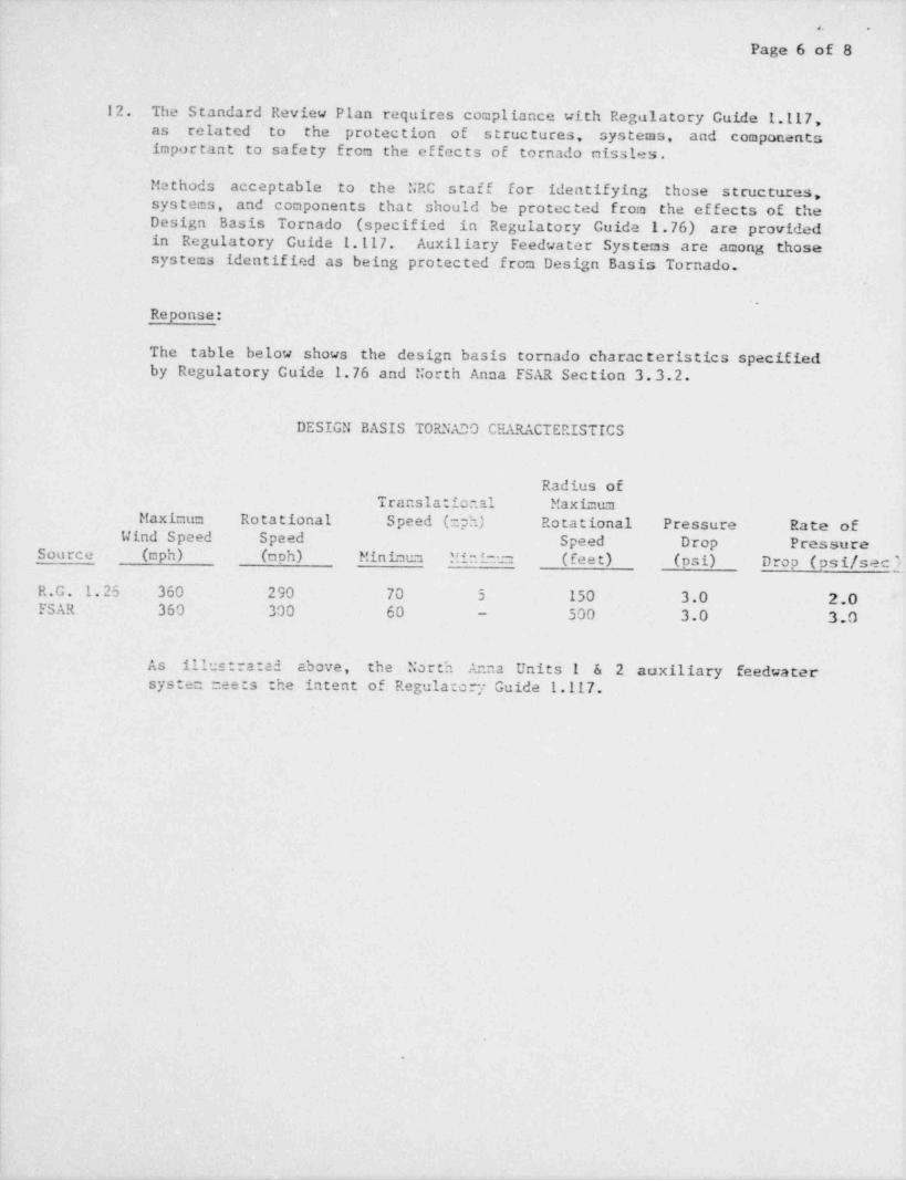
12. The Standard Pseview Plan requires compliance with Regulatory Guide 1.117,as. related 'to the protection of structures, systems, and componentsimportant to safety from the effects of tornado missles.
Methods acceptable to the NRC staff for identifying those s t ructures,systems, and components that should be protected from the effects of the
' Design Basis Tornado ,(specified in Regulatory Guide 1.76) are providedin Regulatory Guide 1.117. Auxiliary Feedwater Systems are among thosesystems identified as being protected from Design Basis Tornado.
.
.
Reponse:
The table below shows the design basis tornado characteristics specifiedby Regulatory Guide 1.76 and North Anna FSAR Section 3.3.2.
DESIGN BASIS TORNADO CHARACTERISTICS
Radius ofTranslatio..al Maximum
Maximum Rotational Speed (2ph) Rotational Pressure Rate ofWind Speed Speed Speed Drop PressureSource (oph) (aph) Minimum *-4~- (feet) (psi) Drop (psi /sec'r
R.G. 1.25 360 290 70 5 150 3.0 2.0FSAR 360 300 60 - 500 3.0 3.0
As illustrated above, the North Anna Units 1 & 2 auxiliary feedwatersystec neets the intent of Regulato y' Guide 1.117.
L
.
,
''' '
Pigm 7 of 8,
>
13. The Standard Review Plan requires compliance with Branch Technical Posi-l' tions ASB 3-1 and MEB 3-1, as related to breaks in high and moderate
energy piping systems outside containment.
- The Branch Technical Position defines a high energy fluid system as:-
" Fluid systems that, during normal plant conditions, .tre eitherin operation or maintained pressurized under conditions whereeither or both of the following are met:
maximum operating temperature exceeds 200*F, o_ra.
b. maximum operating pressure exceeds 275 psig."
Response:
The North Anna FSAR Appendix C defines high energy line breaks in thc'esystems in which both the maximum operating pressure exceeded 275 psigand the maximum operating temperatures equalled or exceeded 200 degrees F.Since the auxiliary feedwater system did not meet the 200 degree Frequirecent, high energy pipe breaks were not considered.
;
|
l
l
|
|
1.. J

-
a,.,
Pagn 8 of 8
14. The Staedard Review Plan requires compliance with Branch Techni.:al Posi-tion ASB 10-1, as related to' auxiliary feedwater pump drive and powersupply diversity.
The auxiliary feedwater system is in compliance with Branch TechnicalPosition ASB 10-1, as related to pump drive and power supply diversity.This is based on the response to NRC question 10.19, statements made bythe NRC staff in the Safety Evaluation Report for tiorth Anna Power StationUnits 1 and 2, dated June 4,1976 and by a recent review of the system.Section 10.5, of the SER states:
" Based on our review, we conclude that the auxiliary feedwatersystem design is in conforcance with our Brm: Technical post-tion APCSB 10-1 regarding diversity of powe. sources, systemficxibility and redundancy including the combination singleac tive failure and high energy line break and is, therefore,acceptable."
.
I
. .,-