8 soil gas movement in unsaturated systems · soil gas movement in unsaturated systems ......
TRANSCRIPT

297
0-8493-0837-2/02/$0.00+$1.50© 2002 by CRC Press LLC
8
Soil Gas Movement in Unsaturated Systems
Bridget R. Scanlon, Jean Phillippe Nicot, and Joel W. Massmann
8.1 GENERAL CONCEPTS RELATED TO GAS MOVEMENT
An understanding of gas transport in unsaturated media is important for evaluation of soil aerationor movement of O
2
from the atmosphere to the soil. Soil aeration is critical for plant root growthbecause roots generally cannot get enough O
2
from leaves. Evaluation of gas movement is alsoimportant for estimating transport of volatile and semivolatile organic compounds from contami-nated sites through the unsaturated zone to the groundwater. The use of soil venting, or soil vaporextraction, as a technique for remediating contaminated sites has resulted in increased interest ingas transport in the unsaturated zone (Rathfelder et al., 1995). Migration of gases from landfills,such as methane formed by decomposition of organic material, is important in many areas (Mooreet al., 1982; Thibodeaux et al., 1982). Soil gas composition has also been used as a tool for mineraland petroleum exploration and for mapping organic contaminant plumes. An understanding of gastransport is important for evaluating movement of volatile radionuclides, such as
3
H,
14
C and Rdfrom radioactive waste disposal facilities. The adverse health effects of radon and its decay productshave led to evaluation of transport in soils and into buildings (Nazaroff, 1992). A thoroughunderstanding of gas transport is required to evaluate these issues.
Gas in the unsaturated zone is generally moist air, but it has higher CO
2
concentrations thanatmospheric air because of plant root respiration and microbial degradation of organic compounds.Oxygen concentrations are generally inversely related to CO
2
concentrations because processesproducing CO
2
generally deplete O
2
levels. Contaminated sites may have gas compositions thatdiffer markedly from atmospheric air, depending on the type of contaminants.
This chapter will focus primarily on processes of gas transport in unsaturated media. Thefollowing issues will be evaluated:
1. How does gas move through the unsaturated zone?2. How does one evaluate single gas and multicomponent gas transport?3. How does one measure or estimate the various parameters required to quantify gas flow?4. How does one numerically simulate gas flow?
Although chemical reactions are discussed in another part of this book, the model equationsdeveloped in this chapter need to be incorporated into them. The reader may find the discussionof water flow in unsaturated media in Chapters 3 and 4 helpful in understanding many of theconcepts in this chapter.
8.1.1 G
AS
C
ONTENT
Unsaturated media consist generally of at least three phases: solid, liquid and gas. In some cases,a separate nonaqueous liquid phase may exist if the system is contaminated by organic compounds.In most cases the pore space is only partly filled with gas. The volumetric gas content (
q
G
) isdefined as:

298
Soil Physics Companion
[8.1]
where
V
G
(L
3
) is the volume of the gas and
V
T
(L
3
) is the total volume of the sample. This definitionis similar to that used for volumetric water content in unsaturated-zone hydrology. In many cases,the volumetric gas content is referred to as the gas porosity. The saturation with respect to the gasphase (
S
G
) is:
[8.2]
where
V
v
(L
3
) is the volume of voids or pores. Saturation values range from 0 to 1. Volumetric gascontent and gas saturation are related as follows:
[8.3]
where
f
is porosity ( ). If only two fluids, gas and water, are in the system, the volumetricgas and water contents sum to the porosity. Therefore, volumetric gas content can be calculated ifthe volumetric water content and porosity are known. Volumetric water content can be measuredusing procedures described in Gardner (1986).
In unsaturated systems, water is the wetting and gas is the nonwetting phase. Therefore, waterwets the solids and is in direct contact with them, whereas gas is generally separated from the solidphase by the water phase. Water fills the smaller pores, whereas gas is restricted to the larger pores.
8.1.2 D
IFFERENCES
BETWEEN
G
AS
AND
W
ATER
P
ROPERTIES
Gas and water properties differ greatly and can be compared as follows: (1) gas density is muchlower than liquid density. The density of air varies with composition but ranges generally from 1to 1.5 kg m
–3
, whereas the density of water is close to 1,000 kg m
–3
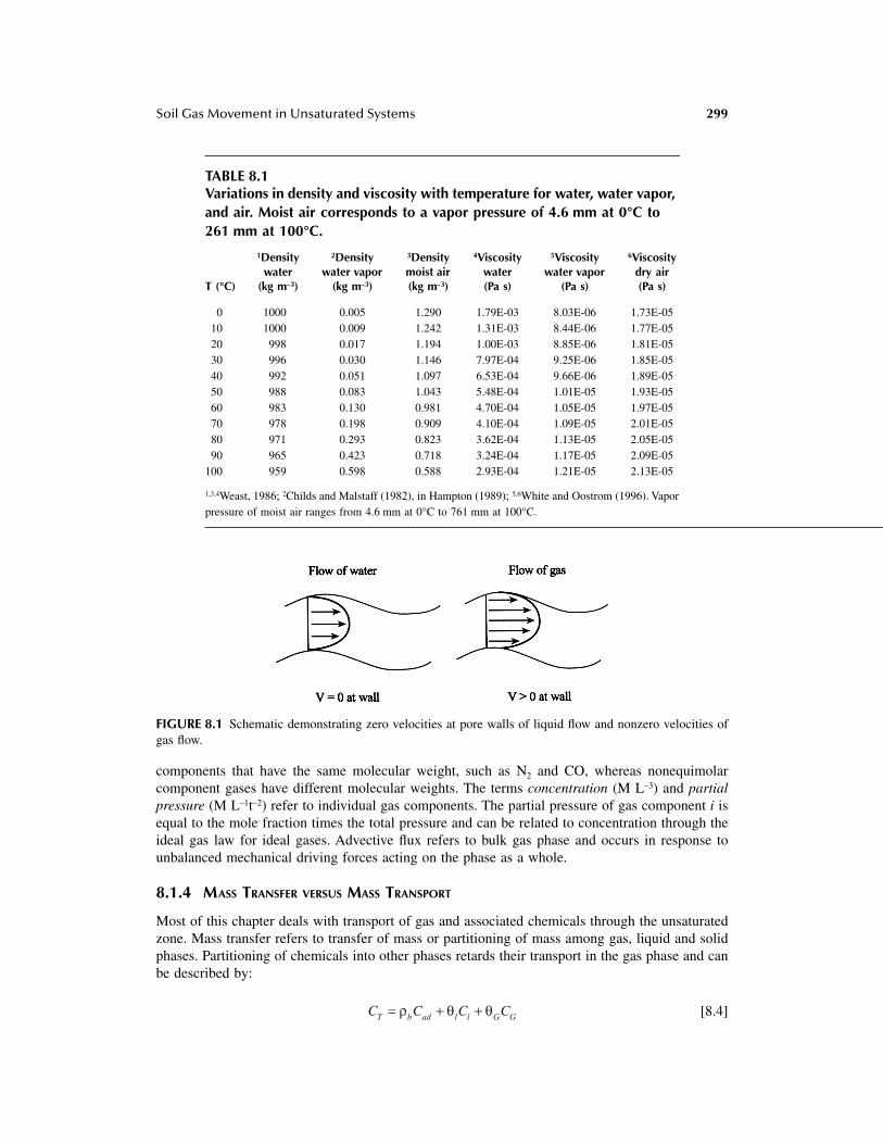
(Table 8.1); (2) although wateris generally considered incompressible, the incompressibility assumption is not always valid forgas flow. Gas density depends on gas pressure, which results in a nonlinear flow equation; (3) atsolid surfaces, water is assumed to have zero velocity whereas gas velocities are generally nonzero,and such velocities result in slip flow or the Klinkenberg effect (Figure 8.1); (4) because the dynamicviscosity of air is ~ 50 times lower than that of water, significant air flow can occur at much smallerpressure gradients. Gas viscosity increases with temperature, whereas water viscosity decreaseswith temperature; (5) air conductivities are generally an order of magnitude less than water orhydraulic conductivities in the same material because of density and viscosity differences betweenthe fluids; (6) because gas molecular diffusion coefficients are about four orders of magnitudegreater than those of water, gas diffusive fluxes are generally much greater than those of water.
8.1.3 T
ERMINOLOGY
Gas refers to a phase that may be single or multicomponent. Gas flux can be expressed in a varietyof ways, such as volume (L
3
L
–2
t
–1
), mass (M L
–2
t
–1
), molar (mol L
–2
t
–1
) or molecular (numberof molecules L
–2
t
–1
) fluxes. If a gas is incompressible, (density constant), then volume and massare conservative, whereas if a gas is compressible only mass is conservative. The mean mass fluxis weighted by the mass of each molecule. In the mean molar or molecular flux all moleculesbehave identically and contribute equally to the mean. The distinction between mass and molarflux will be clarified in Section 8.1.5.4. Parameters important in describing gas transport mecha-nisms include mean free path (
l
), which is the average distance a gas molecule travels beforecolliding with another gas molecule; pore size (
l
p
), which is equivalent to the average distancebetween soil particles in dry porous media; and particle size (r
p
). Equimolar component gases are
qG G TV V= /
S V VG G v= /
q fG GS=
V Vp T/
Soil Gas Movement in Unsaturated Systems
299
components that have the same molecular weight, such as N
2
and CO, whereas nonequimolarcomponent gases have different molecular weights. The terms
concentration
(M L
–3
) and
partialpressure
(M L
–1
t
–2
) refer to individual gas components. The partial pressure of gas component
i
isequal to the mole fraction times the total pressure and can be related to concentration through theideal gas law for ideal gases. Advective flux refers to bulk gas phase and occurs in response tounbalanced mechanical driving forces acting on the phase as a whole.
8.1.4 M
ASS
T
RANSFER
VERSUS
M
ASS
T
RANSPORT
Most of this chapter deals with transport of gas and associated chemicals through the unsaturatedzone. Mass transfer refers to transfer of mass or partitioning of mass among gas, liquid and solidphases. Partitioning of chemicals into other phases retards their transport in the gas phase and canbe described by:
[8.4]
TABLE 8.1Variations in density and viscosity with temperature for water, water vapor, and air. Moist air corresponds to a vapor pressure of 4.6 mm at 0°C to 261 mm at 100°C.
T (°C)
1
Density water
(kg m
–3
)
2
Density water vapor
(kg m
–3
)
3
Density moist air (kg m
–3
)
4
Viscosity water (Pa s)
5
Viscosity water vapor
(Pa s)
6
Viscosity dry air (Pa s)
0 1000 0.005 1.290 1.79E-03 8.03E-06 1.73E-0510 1000 0.009 1.242 1.31E-03 8.44E-06 1.77E-0520 998 0.017 1.194 1.00E-03 8.85E-06 1.81E-0530 996 0.030 1.146 7.97E-04 9.25E-06 1.85E-0540 992 0.051 1.097 6.53E-04 9.66E-06 1.89E-0550 988 0.083 1.043 5.48E-04 1.01E-05 1.93E-0560 983 0.130 0.981 4.70E-04 1.05E-05 1.97E-0570 978 0.198 0.909 4.10E-04 1.09E-05 2.01E-0580 971 0.293 0.823 3.62E-04 1.13E-05 2.05E-0590 965 0.423 0.718 3.24E-04 1.17E-05 2.09E-05
100 959 0.598 0.588 2.93E-04 1.21E-05 2.13E-05
1,3,4
Weast, 1986;
2
Childs and Malstaff (1982), in Hampton (1989);
5,6
White and Oostrom (1996). Vaporpressure of moist air ranges from 4.6 mm at 0°C to 761 mm at 100°C.
FIGURE 8.1
Schematic demonstrating zero velocities at pore walls of liquid flow and nonzero velocities ofgas flow.
C C C CT b ad l l G G= + +r q q

300
Soil Physics Companion
where
C
T
is the total mass concentration (M L
–3
soil);
C
G
,
C
l
, and
C
ad
are the mass concentrationsin the gas and liquid phases and adsorbed on the solid phase; and
r
b
is the bulk density (M L
–3
).The relationship between gas and water mass concentrations can be described by Henry’s law:
[8.5]
where
K
H
is the dimensionless Henry’s law constant. Many types of isotherms describe the adsorp-tion onto the solid phase, the simplest being the linear adsorption isotherm:
[8.6]
where
K
d
(L
3
M
–1
) is the distribution coefficient. The linear relationship generally applies to lowpolarity compounds (Brusseau, 1994).
If linear relationships are valid, total concentration can be written in terms of gas concentrationas follows (Jury et al., 1991):
[8.7]
where
B
G
is the bulk gas phase partition coefficient (Charbeneau and Daniel, 1992). In some studiesthis partitioning behavior is used to quantify the amount of a liquid phase in the system. Forexample, transport of gas tracers that partition into water or nonaqueous phase liquids is comparedwith transport of those that do not partition (conservative) into that phase to determine the amountof water or organic compound in the system (Jin et al., 1995).
8.1.5 M
ECHANISMS
OF
G
AS
T
RANSPORT
Many readers may be more familiar with transport mechanisms in the liquid than in the gas phase.Primary mechanisms of solute transport in the liquid phase include advection (movement with thebulk fluid) and hydrodynamic dispersion (mechanical dispersion and molecular diffusion) (Freezeand Cherry, 1979). Mechanical dispersion, resulting from variations in fluid velocity at the porescale, is the product of dispersivity and advective velocity. Transport in the gas phase may also bedescribed by advection and dispersion. Although some studies have found mechanical dispersionor velocity-dependent dispersion to be important for chemical transport in the gas phase (Rolstonet al., 1969; Auer et al., 1996), in most cases mechanical dispersion is ignored because gas velocitiesare generally too small and the effects of diffusion are generally much greater than dispersion inthe gas phase. Molecular diffusion coefficients are approximately four orders of magnitude greaterin the gas than in the liquid phase.
Diffusive transport in the liquid phase is described by molecular diffusion. Traditionally,diffusive transport in the gas phase has also been described by molecular diffusion. Diffusion inthe gas phase may, however, be much more complicated and may include Knudsen, molecular andnonequimolar diffusion. Surface diffusion of adsorbed gases, generally not significant, is notdiscussed in this chapter. Pressure diffusion results from the separation of gases of differentmolecular weights under a pressure gradient and causes diffusion of heavier (lighter) moleculestoward regions of higher (lower) pressure (Amali and Ralston, 1993). Pressure diffusion is generallynegligible at depths of less than 100 m, which include most unsaturated sections (Amali and Rolston,1993). Although temperature gradients in unsaturated media are generally too low to result insignificant diffusion except at the land surface, thermal diffusion is important for water vaportransport (Section 8.6.3).
C K CG H l=
C K Cad d l=
C K K K C B CT b d H l H G G G G= + + =( / / )r q q

Soil Gas Movement in Unsaturated Systems
301
8.1.5.1 Advective Flux
If a total pressure gradient exists in a soil as a result of external forces such as atmospheric pumping(Section 8.2), gases will flow from points of higher to those of lower pressure. It has been shownthat relatively small gradients in total pressure can result in advective gas fluxes that are muchlarger than diffusive gas fluxes (Alzaydi and Moore, 1978; Thorstenson and Pollock, 1989; Mass-mann and Farrier, 1992). The driving force for flow is the total pressure gradient, and the resistanceto flow is caused by viscosity of the gas. Other terms for advective flux are pressure driven orviscous flux. Under a total pressure gradient, advection is dominant when the mean free path ofthe gas molecules (
l
) is much less than the pore radius (
l
p
) and the particle radius (r
p
) (
l
�
l
p
and
l
�
r
p
), resulting in intermolecular collisions being dominant relative to collisions betweengas molecules and the pore walls (Cunningham and Williams, 1980). Because the mean free pathis inversely proportional to the mean pressure, low mean free paths relative to pore size may occurin dry, coarse-grained media and/or under high mean pressure. A pressure gradient is required tomaintain advective flux because of the velocity reduction near the pore walls caused by gasmolecules rebounding from collisions with the pore walls. In unsaturated media the pore walls willgenerally consist of the gas–liquid interface. Advective flux is also termed nonsegregative ornonseparative because bulk flow as a result of a pressure gradient does not segregate the gas intoindividual components. The viscous flux of gas component
i
is proportional to its mole fraction(
x
i
) in the mixture:
[8.8]
where is the molar viscous flux (mol L
–2
t
–1
) of gas i and is the total molar viscous flux.As the mean pressure and/or as the pore size decrease as a result of decreasing grain size or gassaturation (increasing water saturation), a continuum results, from advective or viscous flux toviscous slip flux (Klinkenberg effect) to Knudsen diffusive flux. Viscous slip flux occurs when themean free path of the gas molecules becomes approximately the same as the pore radius and resultsfrom nonzero velocity at the pore wall. Stonestrom and Rubin (1989) and Detty (1992) found thaterrors resulting from ignoring viscous slip flux in dry, coarse-grained porous media (sands) wereless than 7%.
8.1.5.2 Knudsen Diffusive Flux
Knudsen flux occurs when the gas mean free path is much greater than the pore radius (
l
>>
l
p
),Knudsen number (K
n
=
l
/
l
p
) = 10 corresponding to the Knudsen regime (Alzaydi, 1975; Abu-El-Sha’r, 1993). Molecule–wall collisions dominate over molecule–molecule collisions. The term
freemolecule flux
is also used to describe Knudsen flux because rebounding molecules do not collidewith other gas molecules. The Knudsen diffusive flux depends on the molecular weights andtemperatures of gases and the radius of the pores. It is not influenced by the presence of otherspecies of gas and is described as follows:
[8.9]
where is the Knudsen molar flux of component
i
(mol L
–2
t
–1
), is the effective Knudsendiffusivity (L
2
t
–1
), and
C
i
is the molar concentration of gas i (mol L
–3
) (Cunningham and Williams,1980). is defined as:
[8.10]
N x NiV
iV=
NiV NV
N D Cik
ik
i= - �
Nik Di
k
Dik
D QRT
Mik
pi
=Ê
ËÁ��̄
0 5.

302
Soil Physics Companion
where
Q
P
is the Knudsen radius (L),
R
is the ideal gas constant (M L2 t–2 T–1 mol–1), T is temperature(T), and Mi is the molecular weight of gas i (M mol–1).
8.1.5.3 Molecular Diffusive Flux
Molecular diffusion is the only type of transport mechanism that occurs under isothermal, isobaricconditions when equimolar pairs of gases (e.g., N2, CO) counterdiffuse in pores whose size is muchgreater than that of the mean free path of the gas molecules. In this case molecule–moleculecollisions dominate over molecule–wall collisions. The molecular diffusive flux depends on gasmolecular weights and temperatures in the pore space and is unaffected by the physical nature ofthe pore walls. Because molecular diffusion results in segregation of the different component gases,it is termed segregative. The molar diffusive flux of component i resulting from molecular diffusion
, in a binary gas mixture under isothermal, isobaric conditions is proportional to the concentrationgradient and is described by Mason and Malinauskas (1983):
[8.11]
where is the effective molecular diffusion coefficient (L2 t–1) and niM is the molar concentrationof gas i (mol L–3) (Abu-El-Sha’r, 1993). The effective diffusion coefficient in porous media iscalculated from the free air diffusion coefficient as follows:
[8.12]
where t is the tortuosity, qG is the gas content and is the free air diffusion coefficient (L2 t–1).Volumetric gas content (qG) accounts for reduced cross-sectional area in porous media relative tofree air, and tortuosity (t) accounts for increased path length. A variety of equations have beendeveloped to calculate tortuosity. The most commonly used equations are those of Penman (1940a,b) and Millington and Quirk (1961) (Table 8.2). The effective diffusion coefficient decreases withincreased water content in unsaturated systems; the rate of decrease is low at low water contentsbecause gas is in the large and water in the small pore spaces. The effective diffusion coefficientdecreases sharply as soils become saturated with water because the large pores become occluded.
8.1.5.4 Bulk Diffusive Flux
Bulk diffusion includes molecular and nonequimolar diffusion. Nonequimolar diffusion occurswhen gas components have different molecular weights. According to the kinetic theory of gases,gas molecules have the same kinetic energy in an isothermal, isobaric system; therefore, lightergas molecules have higher velocities than heavier gas molecules. In a binary mixture of nonequimo-lar gases, the more rapid diffusion of the lighter gas molecules results in a pressure gradient. Suchpressure gradients should be distinguished from external pressure gradients that result in advectiveflux. The flux resulting from the buildup of pressure is diffusive and is called the nonequimolarflux or the diffusive slip flux (Cunningham and Williams, 1980). Because the nonequimolar fluxdoes not result in separation of gas components (nonsegregative), the molar bulk diffusive fluxincludes the segregative molecular diffusive flux and the nonsegregative nonequimolar diffusiveflux:
[8.13]
JiMm
J D niMm
ije
iM= - �
Dije
D Dije
G ij= tq
Dij
N J x NiD
iMm
i jD
j
= +=
Â1
n

Soil Gas Movement in Unsaturated Systems 303
where is the bulk molar diffusive flux of component i (mol L–2 t–1), is the molar diffusiveflux of component i resulting from molecular diffusion, xi is the mole fraction of component i, n
is the number of gas components, and the second term on the right is the nonequimolarflux.
It is important to distinguish between diffusive gas flux with respect to average velocity of thegas molecules (molar velocity) and that with respect to velocity of the center of mass of the gas(mass velocity) because the two are not necessarily the same (Cunningham and Williams, 1980).In nonequimolar gas mixtures, because the lighter gas molecules diffuse more rapidly, the molargas flux moves in the direction in which the lighter gas molecules are moving, whereas the centerof mass of the gas moves in the direction in which the heavier molecules diffuse. The molar andmass fluxes can therefore move in opposite directions.
8.1.6 GAS TRANSPORT MODELS
Darcy’s law is used to model advective or viscous gas transport, and traditionally Fick’s law hasbeen used to model molecular diffusion. The Stefan-Maxwell equations and the dusty gas modelcan also be used to simulate diffusive gas flux. If there is a total pressure gradient in a system,then the diffusive fluxes are calculated relative to the bulk molar flux. The total molar flux iscalculated by adding the molar viscous or advective flux to the bulk molar diffusive flux:
[8.14]
where is the total gas molar flux, is the molar viscous flux and is the molar diffusiveflux of component i. For analysis of transient gas flux, the constitutive flux equations are incorpo-rated into the conservation of mass. If the mass density of the fluid and the diffusion coefficientsare assumed constant, then the transport equation can be written as:
[8.15]
TABLE 8.2Models for estimating tortuosity, �G is the gas content, and � is the porosity; a more complete listing is provided in Abu-El-Sha’r (1993).
Tortuosity (�) times �G Reference Comments
0.66f Penman (1940a, b) experimental
Marshall (1958) pseudotheoretical
Millington (1959) pseudotheoretical
Millington and Quirk (1961) theoretical
Millington and Shearer (1970) theoretical
Lai et al. (1976) experimental
0.435f Abu-El-Sha’r Abriola (1997) experimental
q G( )3 2/
q G( )4 3/
q fG-10 3 2/ /
( ) ( )1 2 2- * -Swxf q
q G7 3/
NiD JiM
m
x Ni jD
j=Â
1
n
N N NiT
iV
iD= +
NiT Ni
V NiD
∂∂
( )Cx
tNi
iT+ � ◊ ( ) = 0

304 Soil Physics Companion
where C is the molar concentration of the gas (mol L–3) and xi is the mole fraction of componenti (Massmann and Farrier, 1992). This equation is strictly valid for relatively dilute gas mixtures orfor vapors with molecular weights close to the average molecular weight of air (Bird et al., 1960).
8.1.6.1 Darcy’s Law
Darcy’s law is used to describe advective gas transport. The simplest form of Darcy’s law is asfollows:
[8.16]
where JG is the volumetric flux (L3 L–2 t–1), kG is the permeability (L2), µG is the dynamic gasviscosity (M L–1 t–1), and � P is the applied pressure gradient. Gravity gradients, assumed negligiblehere, are treated in Section 8.2.1. The ideal gas law can be used to convert the volumetric gas flux(JG) to the molar gas flux (NV):
[8.17]
where n is the number of moles of the gas, M is the molar mass of the gas, R is the ideal gasconstant (M L2 t–2 T–1 mol–1) and T is temperature (K). The molar viscous or advective flux is:
[8.18]
The validity of Darcy’s law can be evaluated by plotting the gas flux for a single component againstthe pressure gradient. The relationship should be linear with a zero intercept if Darcy’s law is valid.
8.1.6.2 Fick’s Law
Fick’s law is an empirical expression originally developed to describe molecular diffusion of solutesin the liquid phase. Fick’s law is generally used to describe molecular diffusion of gas i in gas j(Bird et al., 1960; Jaynes and Rogowski, 1983):
[8.19]
where C is the total molar concentration (mol L–3, constant in an isothermal, isobaric system) andxi is the mole fraction of gas and (Bird et al., 1960). Fick’s law is strictly applicable tomolecular diffusion of equimolar gases in isothermal, isobaric systems. Fick’s law excludes theeffects of Knudsen diffusion and nonequimolar diffusion. Fick’s law can predict the flux of onlyone component. The adequacy of Fick’s law will be discussed after the other models have beendescribed.
8.1.6.3 Dusty Gas Model
In contrast to Fick’s law, which is empirical, the dusty gas model is based on the full ChapmanEnskog kinetic theory of gases. Application of the kinetic theory of gases is only possible byconsidering the dust particles (porous medium) as giant molecules that constitute another componentin the gas phase. The multicomponent equations, which are based on the dusty gas model originallyproposed by Mason et al. (1967), are presented by Satterfield and Cadle (1968), Cunningham and
Jk
PGG
G
= - �m
PV nRTnMV
PMRTG= = =, r
NP
RT
kPV G
G
= - �m
J D C xiMm
ij i= - �
D Dij ji=

Soil Gas Movement in Unsaturated Systems 305
Williams (1980), Mason and Malinauskas (1983), and Thorstenson and Pollock (1989). The equa-tions for the dusty gas model of binary and multicomponent gas diffusion are (Cunningham andWilliams, 1980):
[8.20]
where xi is the mole fraction of component i, is the bulk molar diffusive flux of gas componenti (mol L–2 t–1), is the effective molecular diffusivity (L2 t–1), is the effective Knudsendiffusivity (L2 t–1), and Pi is the partial pressure of component i (M L–1t–2). Although one generallywrites equations in terms of a flux of a component being proportional to a gradient, multicomponentgas equations are simplest when written in terms of a gradient of gas component i being proportionalto the fluxes of all other components (Mason and Malinauskas, 1983). Derivation of the aboveform of these equations for a binary gas mixture is shown in Section 8.7. Knudsen diffusion isimportant when the second term in the dusty gas model is larger than the first term. This requiresthat which appears counterintuitive (Thorstenson and Pollock, 1989), but which can beunderstood if one considers the reciprocal of as a resistance. Knudsen diffusion is thus importantwhen is large and is small. Although there is a gradient in the natural log of temperaturein the dusty gas model (Thorstenson and Pollock, 1989), gradients in temperature in the subsurfaceare generally small and gradients in the natural log of temperature are generally negligible. It hastherefore been omitted in Equation [8.20]. The primary assumptions of the dusty gas model arethat the dust particles are spherical and that there are no external forces on the gas. The dusty gasmodel can predict the flux of all components in a gas mixture. The system of equations can besolved analytically (Jackson, 1977) or numerically (Massmann and Farrier, 1992). Many analysesof the dusty gas model assume steady-state flow (Thorstenson and Pollock, 1989; Abu-El-Sha’r,1993).
When both partial and total pressure gradients are important for gas flux, the combined effectsof advection and diffusion need to be considered. Knudsen diffusion, which is proportional to thetotal mole fraction, provides the link between advection and diffusion. Because the dusty gas modelis the only model that includes Knudsen diffusion, it is the only model that can theoretically linkadvection and diffusion through the Knudsen diffusion term. The dusty gas model for combinedadvection and diffusion is as follows (Thorstenson and Pollock, 1989):
[8.21]
where xi is the mole fraction of component i, is the total molar gas flux of component i relativeto a fixed coordinate system (mol L–2, t–1), De
ij is the effective molecular diffusion coefficient ofcomponent i in j (L2 t–1), is the effective Knudsen diffusion coefficient of component i (L2
t–1), P is pressure (M L–1 t–2), R is the ideal gas constant, T is absolute temperature, k is permeability(L2) and µG is gas viscosity (M L–1 t–1).
x N x N
D
N
D
P
RT
x N x N
D
N
D
P
RT
molecular Knudsen P gradientdiffusion diffusion term
D D
e
D
k
i jD
j iD
ije
iD
ik
i
ii j
1 2 2 1
12
1
1
1
1
- - = �
-- = �
=π
Ân
NiD
Dije Di
k
D Dik
ije«
Dik
1 / Dik Di
k
x N x N
D
N
D
P x
RTkP
D
x P
RTi j
Tj i
T
ije
jj i
v
iT
ik
i
ik
G
i-
- = � + +Ê
ËÁ��̄
�
ππ
Â1
1m
NiT
DijK

306 Soil Physics Companion
8.1.6.4 Stefan-Maxwell Equation
The Stefan-Maxwell equations, which can predict the fluxes of all but one gas component in amulticomponent gas mixture, can be obtained from the dusty gas model by assuming negligibleKnudsen diffusion (no molecule particle collisions):
[8.22]
8.2 TRANSPORT OF A HOMOGENEOUS GAS
Transport of a homogeneous gas in dry, coarse-grained media can be described by advection. Becausesuch a gas can be considered as a single component, the only type of diffusion possible is Knudsendiffusion. Single-component gases in dry, coarse-grained media are dominated by advective or viscousflux because Knudsen diffusion is negligible in such systems. This analysis of gas transport is appro-priate when gas velocities are high. The single fluid, nonreactive, noncompositional approximation isappropriate only when one is interested in the bulk flow of a homogeneous gas.
Natural advective gas transport can occur in response to barometric pressure fluctuations, windeffects, water-table fluctuations, density effects, and can also be induced by injection or extraction,as in soil vapor extraction systems. Barometric pressure fluctuations consist of (1) diurnal fluctu-ations due to thermal and gravitational effects, which are on the order of a few millibars, and (2)longer term fluctuations that result from regional scale weather patterns, which are on the order oftens of millibars within a few hours of when a high or low pressure front moves through. Thepenetration depth of barometric pressure fluctuations increases with the thickness of the unsaturatedzone and with the permeability of the medium. Because highs are balanced by lows, the net transportof the gas may be negligible, except in fractured media, where contaminants may migrate largedistances (Nilson et al., 1991). Smaller scale fluctuations, such as gusts and lulls related to wind,may be important in fractured media (Weeks, 1993). Water-table fluctuations, resulting in changesin the gas volume, can produce advective flow; however, advective fluxes as a result of water-tablefluctuations are considered important only if the rate of rise or decline of the water-table is rapid,the permeability of the material is high and the water table is shallow.
8.2.1 GOVERNING EQUATIONS
Darcy’s law, which was developed for water flow in saturated media, can also be applied to single-phase gas flow. Darcy’s law is an empirical expression and the general form is:
[8.23]
where JG is the volumetric flux density (L3 L–2 t–1), kG is gas permeability (L2), rG is gas density(M L–3), g is gravitational acceleration (L t–2), µG is gas viscosity (M L–1 t–1), P is pressure (M L–1
t–2), and z is elevation (L). The negative sign in Equation [8.23] is required because flow occurs inthe direction of decreasing pressure. The first term in parentheses is the driving force due to pressureand the second term is the driving force due to gravity. Generally gas density is a function ofpressure and composition, and the above form of Darcy’s law is the only valid form in these cases.The pressure gradient provides the main driving force for advective gas transport, and the resistanceto flow results from the gas viscosity. Small pressure gradients can result in substantial advective
x N x N
D
P
RTi j
Dj i
D
ije
i
jj i
-=
�
=π
Â1
n
Jk
P g zGG
GG= - � + �( )m
r

Soil Gas Movement in Unsaturated Systems 307
gas fluxes because the resistance to flow is small. The small flow resistance is attributed to thenegligible viscosities of gases relative to those of liquids and to the gas being present in the largestpores. If the components of a gas all have the same molecular mass, then gas density is independentof composition and is only a function of pressure.
Under static equilibrium and isothermal conditions, gas does not move. If the only forcesoperating on the gas are pressure and gravity, then these two forces must be balanced. The conditionof zero motion results when:
[8.24a]
[8.24b]
If gas density varies because of variable composition, the above equation cannot be simplifiedfurther. If the gas is barotropic (i.e., rG = rG(P) only), however, the ideal gas law (Equation [8.17])can be used to relate density and pressure when pressure variations are close to atmospheric.Equation [8.24a] can be solved through integration by inserting the ideal gas law:
[8.25]
where P is assumed to be equal to P0 at z = 0. If z = 1 m, T = 290 K, R is 8.314 J mol–1 K–1, M is28.96 g mol–1 (air), and g is 9.8 m s–2, then P = 0.99988 P0. Gas pressure therefore changes by0.012% over a height of 1 m. Because the gas pressure changes are so small, pressure can generallybe considered independent of height.
If gas density is only a function of pressure, (compressible gas), Equation [8.23] can bemanipulated to obtain:
[8.26]
If gas density is independent of pressure, then the gas is incompressible:
[8.27]
[8.28]
where h is pressure head (L) and H is total head (L, pressure + gravitational head). Because gasdensities are generally very low (density of air is approximately three orders of magnitude less
� = - �P g zGr
dP
dzgG= -r
RTgM
dPP
dzRTgM
PP
z
P PMgRT
z
P
P
z
z
0 00
0
Ú Ú= -ÊËÁ
��̄ = -
= -ÊË
�¯
; ln
exp
qk P
g zk dP
g zGG G
G G
G G
G GP
P
= - � + �Ê
ËÁ��̄ = - � + �
Ê
ËÁÁ
�
¯��Úr
m rr
m r0
� = �Ê
ËÁ��̄Ú dP P
G GP
P
r r0
qk g P
gz
k gh z
k gHG
G G
G G
G G
G
G G
G
= - �Ê
ËÁ��̄ + �
Ê
ËÁ
�
¯� = - � + �( ) = - �( )r
m rr
mr
m
308 Soil Physics Companion
than water density), the gravitational term in Equation [8.23] ( ) is generally < 1% of thepressure term and is ignored in most cases, as shown in Equation [8.16]. For transient gas flow,Darcy’s law (ignoring gravity, Equation [8.16]), substituted into the conservation of mass equation,results in:
[8.29]
Equation [8.29] is nonlinear because gas density depends on gas pressure and can be linearized interms of P2 by assuming ideal gas behavior (Equation [8.17]), which results in (Section 8.7):
[8.30]
where is the pneumatic diffusivity (a). If pressure variations are small, another linearapproximation to Equation [8.29] can be obtained:
[8.31]
Derivations of Equations [8.30] and [8.31] are given in Section 8.7.
8.2.2 GAS PERMEABILITY
Gas permeability describes the ability of the unsaturated zone to conduct gas. Permeability (k)should be simply a function of the porous medium if the fluid does not react with the solid. Gaspermeability (kG; L2) is related to gas conductivity (KG) as follows:
[8.32]
Some groups use the term gas permeability for KG, which is called gas conductivity, and use theterm intrinsic permeability for kG,which is called gas permeability. Equation [8.32] shows that gasconductivity increases with gas density and decreases with gas viscosity.
The above material describes single-phase gas flow. In unsaturated media, the pore spacegenerally contains at least two fluids, gas and liquid. Darcy’s law is applied to each fluid in thesystem, which assumes that there is no interaction between the fluids (Dullien, 1979). Because thecross-sectional area available for flow of each fluid is less than if the system were saturated witha single fluid, the permeability with respect to that fluid is also less. The gas permeability decreasesas the gas saturation decreases. The relative permeability ( ) is a function of the gas saturation( ) and is defined as the permeability of the unsaturated medium at a particular gas saturation( ) divided by the permeability at 100% saturation ( ):
[8.33]
Relative permeability varies with (1) fluid saturation, (2) whether the fluid is wetting or nonwetting,and (3) whether the system is wetting or drying (hysteresis).
rGg z�
∂ r q∂
rm
( )G G G G
Gt
kP= -� ◊ - �
Ê
ËÁ��̄
∂∂ fm
aP
t
k PP PG
G
20 2 2 2 2ª � ª �
k PG G0 fm
∂∂ fmP
t
k PPG
G
= �0 2
K kg
G GG
G
=rm
krG
SG
k SG G( ) kG
k S k S krG G G G G( ) ( ) /=

Soil Gas Movement in Unsaturated Systems 309
The relative permeability of the gas phase is greater than that of the liquid phase at low tomoderate liquid saturations because the gas generally occurs in larger pores (Demond and Roberts,1987). Relative permeabilities do not sum to one. This has been attributed to flow pathways traversedby two fluid phases being more tortuous than those traversed by a single phase (Scheidegger, 1974)or to pores with static menisci that cannot result in flow (Demond and Roberts, 1987). Zero relativepermeabilities correspond to nonzero fluid saturations (Figure 8.2). For example, in systems initiallywater saturated that begin to drain, gas will not begin to flow until a minimum gas saturation hasbeen reached, the residual gas saturation (SrG; Figure 8.2). The gas zero relative permeability regioncorresponds to trapped gas and disruption of gas connectivity caused by water blockages (Stone-strom and Rubin, 1989). Liquid-phase permeability also exhibits a zero-permeability region thatcorresponds to residual liquid or water saturation (Chapter 3). In natural systems, the zone ofresidual water saturation corresponds to a zone of constant gas relative permeability because gascontent does not increase. The dashed line in Figure 8.2 in this zone corresponds with furtherincreases in gas relative permeability (krG), which is related to increased gas content if the soil isoven dried and the water content is reduced to zero. A similar effect occurs with the water relativepermeability (krw), where the dashed line shows increased water relative permeability correspondingto vacuum saturation or saturation of the sample under back pressure. Gas permeability is hystereticat low water content, which indicates that gas permeability is not a unique function of gas saturationbut depends on saturation history (i.e., whether the system is drying or wetting). At a given saturation,gas permeability is generally greater for wetting than for drying (Stonestrom and Rubin, 1989).
Various expressions have been developed to relate relative permeability to gas saturation(Table 8.3). Many of the expressions were developed to estimate relative permeabilities with respectto water; the corresponding expressions for gas relative permeability were obtained by replacingthe effective liquid saturation (Se) by 1-Se, where Se is:
[8.34]
where Sr is the residual water saturation (Brooks and Corey, 1964).Darcy’s law can be written as:
[8.35]
FIGURE 8.2 Schematic relative permeabilities with respect to gas and water saturation.
SS S
Ser
r
=--1
Jk S k
Pk S
PGrG G G
G
G G
G
= - �( ) = - �( ) ( )
m m

310 Soil Physics Companion
The velocity of the gas particles (VG) (L t–1) can be calculated from the volumetric flux density bydividing by the volumetric gas content:
[8.36]
8.2.3 DEVIATIONS FROM DARCY’S LAW
Non-Darcian effects such as viscous slip flow and inertial flow can occur under many circumstances.As mentioned earlier, gas flow differs from liquid flow in that the velocity of the gas molecules isnonzero at the pore walls (Figure 8.1) and is called slip velocity (Dullien, 1979). Slip flow, or theKlinkenberg effect, results in underestimation of gas flux by Darcy’s law. Because of slip flow,permeability depends on pressure and the flow equation is nonlinear (Collins, 1961). Klinkenberg(1941) evaluated the relationship between slip-enhanced, or apparent, permeability kG (L2) and thepermeability at infinite pressure k (L2) when the gas behaves like a liquid:
[8.37]
where c is a constant characteristic of the porous medium, l is the mean free path of the gas atthe mean pressure, and is the mean pore radius (Klinkenberg, 1941). Because the mean freepath is inversely proportional to the mean pressure in the system, the equation can be modified to:
[8.38]
where is the mean pressure and bi (M L–1 t–2) is a constant (slip parameter) that depends on theporous medium and the gas i used in the measurement (Klinkenberg, 1941). These two equationsshow that gas slippage, or slip-enhanced permeability, is enhanced when the mean pressure is low.As the mean pressure increases, gas permeability decreases and approaches liquid permeability.
TABLE 8.3Expressions relating relative gas permeability and saturation. Se is the effective saturation with respect to water; Se = (Sw – Srw)/(1 – Srw), Srw is the residual wetting phase saturation (water in water-air system), � is the bubbling pressure, and m and n are fitting parameters.
Brooks and Corey (1964)
Corey (1954)
Falta et al. (1989)
van Genuchten (1980); Mualem (1976)
van Genuchten (1980); Burdine (1953)
k S SrG e e= -( ) -Ê
ËÁ
�
¯�
+
1 12
2 ll
k S SrG e e= - -( ) ( )1 12 2
k SrG e= -( )1 3
k S SrG e e
m m
= -( ) - - -( )[ ]ÏÌÓ
¸ýþ
1 1 1 10 5 12
. /m n
m
= -
< <
1 2
0 1
/
k S SrG e e
m m
= -( ) - - -( )ÈÎÍ
ùûú
ÏÌÓ
¸ýþ
1 1 1 12 1/ m n
m n
= -
< < >
1 2
0 1 2
/
;
V JG G G= / q
k kc
Gp
= +È
ÎÍÍ
ù
ûúú
14 ll
l p
k kb
PGi= +Ê
ËÁ��̄1
P

Soil Gas Movement in Unsaturated Systems 311
Detty (1992) found that the slip parameter is not only a function of the reciprocal mean pressureas indicated by Klinkenberg (1941), but also a function of the pressure gradient and saturation.Slip correction factors measured in unconsolidated sands are generally fairly low (1 to 6%)(Stonestrom and Rubin, 1989; Detty, 1992) and resemble those measured in consolidated sands(Estes and Fulton, 1956).
Non-Darcian behavior can also occur at high flow velocities as a result of inertial effects.According to Darcy’s law, the flux is linearly proportional to the pressure gradient. At high flowvelocities, the relationship becomes nonlinear and inertial effects result in fluxes lower than thosepredicted by Darcy’s law. Forcheimer (1901) modified Darcy’s law for high velocities:
[8.39]
where P is pressure, µG is gas viscosity, JG is volumetric gas flux, and b is the inertial flow factor(L–1) (Detty, 1992). The second-order term results from kinetic energy losses from high-velocityflows. There is a spectrum from viscous (linear–laminar or Darcy flow) to inertial flow (fullyturbulent) with a visco-inertial regime in between. Laminar flow is not restricted to the regionwhere Darcy’s law is valid, but extends into the visco-inertial regime where nonlinear–laminar flowoccurs (q ~ � Pn) (Detty, 1992). Detty (1992) indicated that deviations from viscous flow can besignificant. The flow rates and pressure gradients that result in visco-inertial flow vary with watersaturation.
8.3 MULTICOMPONENT GAS TRANSPORT
In isobaric systems, gas transport occurs by diffusion, whereas in nonisobaric systems gas transportoccurs by advection (Darcy’s law) and diffusion. A variety of models are available to describemulticomponent gas diffusion. Traditionally, gas diffusion has been described by Fick’s law. Asnoted earlier, Fick’s law is valid strictly for isothermal, isobaric and equimolar countercurrentdiffusion of a binary gas mixture. Theoretical analysis by Jaynes and Rogowski (1983) shows thatthe diffusion coefficient of Fick’s law is only a function of the porous medium under certainconditions: equimolar countercurrent diffusion in a binary gas mixture, diffusion of a dilute com-ponent gas in a multicomponent gas mixture, and diffusion in a ternary system when one gascomponent is stagnant (zero flux, no sources or sinks, no reactions). Studies by Leffelaar (1987)indicate that if binary gas diffusion coefficients differ by more than a factor of 2, then Fick’s lawis invalid. Amali and Rolston (1993) also added that the total mole fraction of the diffusing gascomponents needs to be considered and should be low in order for Fick’s law to be applicable.
If the flux of each gas component depends on the flux of the other gas components, then Fick’slaw no longer applies. In some cases, the calculated Fick’s law flux is not only different in magnituderelative to multicomponent molecular diffusive flux, but opposite in direction also, as a result ofmolecular diffusion against a concentration gradient (Thorstenson and Pollock, 1989). BecauseFick’s law predicts the diffusion of only one component, variations in concentration of othercomponents are attributed to other processes. Baehr and Bruell (1990) showed that physicaldisplacement of naturally occurring gases such as O2 by organic vapors and evaporative advectivefluxes can be incorrectly attributed to aerobic microbial degradation or other sink terms when Fick’slaw is used. Unlike Fick’s law, which can only consider binary gas mixtures, the Stefan-Maxwellequations or the dusty gas model can evaluate multicomponent gas transport. For multicomponentanalysis, the transport of one component depends upon the transport of all other components that arepresent in the gas mixture. It is impossible to separate fully the effects of diffusion from those ofadvection in multicomponent gas systems (Thorstenson and Pollock, 1989). As noted earlier, Stefan-Maxwell equations are valid strictly for isobaric systems where Knudsen diffusion is negligible.
� = +PJ
kJG G
GG G
mbr 2

312 Soil Physics Companion
The validity of the single-component advection–diffusion (Fick’s law) equation for simulatinggas phase transport depends on the pore sizes and permeability of the porous media, the relativeconcentrations of the gas components that are involved, and their molecular weights, viscositiesand pressure gradients. Massmann and Farrier (1992) compared fluxes using the single-componentadvection–diffusion equation with those calculated using the multicomponent Stefan-Maxwellequation and dusty gas model. The comparisons were developed for transport conditions similarto what might be observed in volatile organic compounds (VOCs) in the near surface vadose zone.For total pressure gradients ranging from 100 to 1,000 Pa m–1 (1 to 10 mbar m–1), the single-component advection–diffusion (Fick’s law) equation significantly overestimates fluxes for tolueneand trichloroethylene (TCE) in soils having permeabilities on the order of 10–16 to 10–17 m2
(Figure 8.3a). These permeabilities might correspond to unweathered clays, glacial tills or very finesilts (Table 8.4). The Stefan-Maxwell equations also overestimate fluxes in this permeability rangebecause Knudsen diffusion is not included in Fick’s law or in the Stefan-Maxwell equations(Figure 8.3b). The flux predicted by the single-component advection–diffusion equation is withina factor of 2 of that predicted by the dusty gas model in materials having permeabilities greaterthan 10–14 m2. This permeability corresponds to a relatively dry silty-sand material (Table 8.4). TheStefan-Maxwell equation underestimates fluxes in high-permeability materials for moderate totalpressure gradients (0.1 to 1 mbar m–1; 10 to 100 Pa m–1) (Figure 8.3b). Massmann and Farrier(1992) also illustrated how multicomponent equations may result in situations in which diffusioncan occur in a direction opposite that of the partial-pressure gradients. In multicomponent equations,the diffusive flux of one component depends on the diffusive fluxes of all other components in thesystem. For example, a large partial-pressure gradient for TCE can cause the diffusive flux of N2
and O2 to occur in a direction opposite to their partial pressure gradients. In general, singlecomponent equations will be more valid for dilute gases having molecular weights similar to thoseof other species in the gas mixture.
Abriola et al. (1992) evaluated advective and diffusive fluxes in a system comprising twocomponents. They reported that under an applied total pressure gradient of 0.05 mbar m–1 (5 Pam–1), the single and multicomponent models give virtually indistinguishable results for transportpredictions in a sandy soil. For transport in a low permeability material, such as a clay under atotal pressure gradient of 0.05 mbar m–1, diffusive fluxes dominate, and single- and multicomponentequations give different transport predictions. Multicomponent gas experiments that evaluatedtransport of methane and TCE in air were examined by Abu-El-Sha’r (1993). The system wasevaluated as either a binary (considering N2 and O2 in air as a single component with methane orTCE as the other component) or a ternary system. Results of the experiments showed that modelpredictions based on Fick’s law, the Stefan-Maxwell equations and the dusty gas model were
FIGURE 8.3 (a) Ratios of TCE fluxes calculated using the single-component equation (Fick’s law for diffu-sion) divided by fluxes calculated using the dusty gas model; (b) ratios of TCE fluxes calculated using theStefan-Maxwell equation divided by fluxes calculated using the dusty gas model (Massmann and Farrier, 1992).

Soil Gas Movement in Unsaturated Systems 313
indistinguishable in sand samples, whereas the dusty gas model provided slightly better predictionsin kaolinite. All three models can therefore predict diffusional gas fluxes under isobaric conditionswhen transport is dominated by molecular diffusion. However, under pressure gradients, deviationsof measured and predicted values of gas fluxes increased with increasing total pressure gradients.All three models underestimated gas fluxes under nonisobaric conditions. Deviations from measuredfluxes were lowest for the dusty gas model, increased for the Stefan-Maxwell equations, and weregreatest for Fick’s law. Theoretical analysis by Thorstenson and Pollock (1989) indicates thatmulticomponent analysis using the dusty gas model is required for evaluation of stagnant gasessuch as N2 or Ar in the air. Analysis of transient gas flux on the basis of column experiments usingbenzene and TCE shows that Fick’s law and the Stefan-Maxwell equations give similar results inthe transient phase of the experiment, but that Fick’s law underestimates measured fluxes by asmuch as 10% in the steady-state phase. The Stefan-Maxwell equations gave much better results(Amali et al., 1996).
These studies were used to develop Table 8.5, which generally outlines which models are mostapplicable under which pressure, permeability and concentration conditions. For low-permeabilitymaterial, the dusty gas model is required because it incorporates Knudsen diffusion. For high-permeability material under isobaric conditions, Fick’s law can be used if the diffusing gas com-ponent has a low concentration, whereas the Stefan-Maxwell equation is required if concentrationis high because of the interdependence of flux. The Stefan-Maxwell equations or the dusty gasmodel can be used when Fick’s law applies. Similarly, the dusty gas model can also be used whenthe Stefan-Maxwell equations are valid. Under nonisobaric conditions, Darcy’s law is combinedwith a diffusion model. The single-component advection diffusion (Fick’s law) model can be usedin low concentration situations in high-permeability material, whereas the dusty gas model isrequired in high concentration situations. The Stefan-Maxwell equations generally do not apply
TABLE 8.4Typical values of permeability for different types of sediments and rocks.(From Terzaghi and Peck, 1968, John Wiley & Sons, New York.)
10–7 10–8 10–9 10–10 10–11 10–12 10–13 10–14 10–15 10–16 10–17 10–18 10–19 10–20 m2
Clean gravel
Clean sands, clean sand and gravel mixtures
Very fine sands, silts, mixtures of sand, silt, and clay, stratified clay deposits, etc.
Homogeneous clays below zone of weathering
(From Freeze and Cherry, 1979, Groundwater, 604, Table 2.2, p. 29, Prentice-Hall,Englewood Cliffs, NJ.)10–7 10–8 10–9 10–10 10–11 10–12 10–13 10–14 10–15 10–16 10–17 10–18 10–19 10–20 m2
Gravel
Clean sand and silty sand
Silt, loess
Glacial till
Unweathered marine clay
Shale

314 Soil Physics Companion
under nonisobaric conditions (Massmann and Farrier, 1992; pressure gradients > 10 Pa m–1,Figure 8.3b).
8.3.1 DENSITY-DRIVEN ADVECTION
Density-driven advective transport, a specific type of multicomponent gas transport, is importantfor high molecular-weight compounds that have high vapor densities, such as dense volatile organiccontaminants (Falta et al., 1989; Mendoza and Frind, 1990; Mendoza and McAlary, 1990). Impor-tant factors controlling density-driven advective flow include saturated vapor density, molecularmass of the chemical, and gas phase permeability. Vapor densities are maximized when the airmixture is saturated by the vapor phase of the chemical. Such high saturations are restricted toareas close to the free phase. Numerical simulations indicate that density-driven advective flow inhomogeneous media is important at the high permeabilities (> 10–11 m2) typical of sands and gravels(Falta et al., 1989). The presence of fractures can greatly enhance density-driven advective flow.
An order of magnitude estimate of the advective gas flux resulting from density variations maybe obtained from (Falta et al., 1989):
[8.40]
Equation [8.40] describes steady-state downward flux of fluid of density r through a stagnant fluidof density in material of permeability and ignores diffusion and phase partitioning. Anestimate of the density potential of the gas mixture (r) with respect to air (r0) can be obtainedfrom relative vapor density (rrv) (Mendoza and Frind, 1990):
[8.41]
where xc is the fractional molar concentration of the compound and Mc and Ma are the molecularweights of the compound and air, respectively. Relative vapor density of the source depends on thevapor pressure and molecular weight of the compound (Mendoza and Frind, 1990). Density-drivenadvection occurs generally in areas contaminated by high-molecular-weight volatile organic con-taminants that have high vapor densities.
TABLE 8.5Most appropriate model for describing gas flux under different pressure, permeability and concentration conditions. Pressure gradient refers to the existence of an external pressure gradient, concentration refers to concentration of the diffusing gas component, dusty gas model* includes Darcy’s law to describe advective gas flow.
Pressure Gradient Permeability Low Concentration High Concentration
Isobaric low dusty gas model dusty gas modelIsobaric high Fick’s law Stefan-MaxwellNonisobaric low dusty gas model* dusty gas model*Nonisobaric high advection diffusion dusty gas model
Jk g
GG
G
= - � -( )m
r r0
r0 kG
r rrrv
c c c a
a
x M x M
M=
+ -
0
1( )

Soil Gas Movement in Unsaturated Systems 315
8.4 METHODS
8.4.1 ESTIMATED PARAMETERS
Because theoretically permeability should be independent of fluid used, gas and liquid permeabil-ities should be the same. In fine-grained media or under small mean pressures, gas permeability isgreater than liquid permeability because of gas slippage (Klinkenberg effect). Permeability can becorrected for gas slippage using Equation [8.38]. If gas slippage is negligible, as in coarse mediahaving high mean pressures, gas conductivity can be estimated from hydraulic conductivity by:
[8.42]
Air conductivities are about one-tenth of hydraulic conductivities because the air density is approx-imately three orders of magnitude less than water density and air viscosity is approximately 50times less than water viscosity (Table 8.1). The estimated gas conductivities (Equation [8.42])assume that pores are completely filled with gas. Typical values of permeability for differentsediment textures are found in Freeze and Cherry (1979) and Terzaghi and Peck (1968) (Table 8.4),and permeability varies over 13 orders of magnitude from clay to gravel.
A rough estimate of gas permeability in gas saturated systems can be obtained from particlesize data:
(Hazen, 1911) [8.43]
(Massmann, 1989) [8.44]
where C is a dimensionless shape factor and D10 and D15 correspond to the grain diameters at which10 or 15% of the particles by weight are finer. Other estimates of exponents include 1.65 and 1.85instead of 2 in the Hazen formula (Shepherd, 1989).
The Klinkenberg b parameter can be estimated according to the following empirical equationdeveloped by Heid et al. (1950) for air-dry consolidated media (standard correction for the Klinken-berg effect by the American Petroleum Industry):
[8.45]
where b is in atmospheres and is in cm2. The Klinkenberg b parameter for any gas (bi) can beestimated from that for air (bair), developed by Heid et al. (1950) according to the following(Thorstenson and Pollock, 1989):
[8.46]
The Knudsen diffusion coefficient is related to the Klinkenberg effect because both are related tothe ratio of the mean free path of the gas molecules to the pore radius. Thorstenson and Pollock(1989) showed how the Knudsen diffusion coefficient ( ) can be estimated from the true perme-ability and the Klinkenberg b parameter for gas i:
[8.47]
K KG wG
w
w
G
=Ê
ËÁ��̄
Ê
ËÁ��̄
rr
mm
k C D= ( )10
2
k D= 1 250 152, ( )
b kair = ¥( )-�-3 98 10 5 0 39. .
k�
b M M bi i air air i air= ( )( )m m/ //1 2
Dik
D kbik
i i= / m

316 Soil Physics Companion
Gas conductivities and permeabilities vary with gas content. Estimates of gas conductivity atdifferent gas saturations are provided by equations listed in Table 8.3.
8.4.2 LABORATORY TECHNIQUES
A variety of laboratory techniques are available for measuring parameters related to gas movement,such as gas pressure and permeability. Gas pressure can be measured with U-tube manometerscontaining different fluids, such as water or mercury. Such manometers generally measure differ-ential pressure because one end of the tube is inserted into soil or rock and the other is exposedto the atmosphere. Manometers can be inclined to increase sensitivity. Pressure transducers areused widely to measure absolute or differential gas pressure. The operational range of theseinstruments varies, and their precision is generally a percentage of the full-scale measurementrange. Manufacturers include Setra (Acton, Massachusetts) and Microswitch Honeywell (Freeport,Illinois). Because transducers are subject to drift, they have to be calibrated periodically. Data canbe recorded automatically in a data logger.
Gas permeability can be measured in the laboratory on undisturbed or repacked cores. Repack-ing should be done only on samples having low clay content. Because repacking changes structure,gas transport parameters are affected. The more structured the soil, the bigger the potential change.Clay soils tend to be more structured. Permeability measurements include determination of flowrate of each phase under an applied pressure gradient and measurement of saturation in unsaturatedsystems (Scheidegger, 1974). Various methods used to measure air and water permeabilities includethose in which both phases move and are measured at the same time and those in which thepermeability of one fluid phase is measured while the other phase remains stationary. Steady-statemethods that hold the wetting phase stationary are used most widely (Corey, 1986). Tempe cells(Soilmoisture Equipment Corp., Santa Barbara, California) used for measuring water retentionfunctions can be adapted as permeameters and include a sample holder with ceramic end plates.Alternatively, if sample shrinkage is expected, flexible wall permeameters can be used to minimizeair flow along the annulus between the sample and the holder. Sharp et al. (1994) described anelectronic minipermeameter for measuring gas permeability in the laboratory. Gas is injected at aconstant pressure and the steady-state flow is measured by electronic mass flow transducers.Permeabilities can be measured over a wide range (10–15 to 10–8 m2). The Hassler method (Hassler,1944) controls the capillary pressure at both ends of a soil core by means of capillary barriers andmeasures air and water relative permeabilities at the same time under a pressure gradient. Thecapillary barriers separate wetting and nonwetting phases. The Hassler method was used by Stone-strom (1987) and by Springer (1993). Other procedures for laboratory measurement of gas perme-ability were described in Springer et al. (1995) and Detty (1992). Darcy’s law is used to estimategas permeability:
[8.48]
Additional equipment required for gas permeability measurements includes a pressure transduceror manometer, a flow sensor such as a soap film bubble meter, and a temperature sensor such asa thermistor. Gas permeabilities are measured at different gas saturations or water contents. If thesample is initially saturated with water, a minimum pressure must be reached (air entry pressure)before a continuous gas phase is achieved. Gas permeability increases as water content decreases.
The Klinkenberg b parameter can be estimated by plotting gas permeabilities measured atdifferent mean pressures ( ) as a function of the reciprocal mean pressure at which the tests wereperformed (Equation [8.38]). Rearranging Equation [8.38] results in:
[8.49]
k S J dP dzG G G G( ) / /= -( ) ( )m
P
k k b P k kb PG i i= +( ) = +1 1/ ( / )

Soil Gas Movement in Unsaturated Systems 317
Therefore, the slope is the product of k times bi and the intercept is the true permeability.Gas diffusivities can be measured in open, semi-open and closed systems (Abu-El-Sha’r, 1993).
An open system involves component gases flowing past the edges of the soil. Pressure gradientsand absolute pressures can be controlled by regulating the flow rate of the component gases. Asemi-open system is generally termed a Stefan tube that consists of the diffusing substance in liquidform at the base and either free air (if measuring free-air diffusivity) or the porous medium (ifmeasuring effective diffusivity of the porous medium) at the top. Closed systems generally consistof two chambers connected by a capillary or chamber filled with the porous medium (Glauz andRolston, 1989). This system can be used in the study of noxious gases. Semi-open systems aregenerally used in hydrology to measure effective binary diffusion coefficients. Fick’s law is gen-erally used to analyze these experiments. Although most studies in the past used nonequimolarpairs of gases, none of these studies considered nonequimolar diffusion. Experiments conductedby Abu-El-Sha’r (1993) were the first to use an equimolar pair of gases (N2 and CO) to determineeffective binary molecular diffusion coefficients. Details of various procedures for measuringmolecular diffusion coefficients are outlined in Rolston (1986).
Single-gas experiments are used to measure the Knudsen diffusion coefficient by applying thedusty gas model (Abu-El-Sha’r, 1993):
[8.50]
Rearranging Equation [8.50] results in:
[8.51]
Plotting versus should result in a straight line with an intercept of and a slopeof , where L is the length of the column in the experiment (Abu-El-Sha’r, 1993).
8.4.3 FIELD TECHNIQUES
8.4.3.1 Estimation of Gas Permeability for Advective Gas Flow
Advective transport of gases depends on gas permeability and pressure gradient. Gas permeabilitycan be estimated from (1) analysis of atmospheric pumping data, (2) pneumatic tests, or (3)measurements by air minipermeameters. Comparison of gas permeabilities from laboratory andfield indicates that field derived estimates of gas permeabilities generally exceed laboratory derivedestimates by as much as orders of magnitude (Weeks, 1978; Edwards, 1994). These differences inpermeability are attributed primarily to the increase in scale from laboratory to field measurementsand inclusion of macropores, fractures and heterogeneities in field measurements. Field permeabilitymeasurements in low permeability media include the effects of viscous slip and Knudsen diffusion.
8.4.3.2 Analysis of Atmospheric Pumping Data
Comparison of temporal variations in gas pressure, monitored at different depths in the unsaturatedzone, with atmospheric pressure fluctuations at the surface can be used to determine minimumvertical air permeability between land surface and monitoring depth (Weeks, 1978; Nilson et al.,1991). Differential pressure transducers are used to monitor gas pressures in the unsaturated zone.Gas ports generally consist of screened intervals in boreholes of varying diameter. Flexible tubing(Cu or nylon) connects the gas port at depth with a differential pressure transducer at the surface.
ND
RT
Pk
RTPi
T ik
G
= - +Ê
ËÁ��̄ �
m
ND
Pk
P
RTPi
T ik
G
G
= - +ÊËÁ
��̄ �
mm
N LRT PiT D P Di
k
k G/ m

318 Soil Physics Companion
One port of the transducer is left open to the atmosphere. Atmospheric pressure is monitored atthe surface by a barometer.
Data analysis consists of expressing the variations in atmospheric pressure as time harmonicfunctions. The attenuation of surface waves at different depths in the unsaturated zone providesinformation on how well or poorly unsaturated sections are connected to the surface. The accuracyof the results increases with the amplitude of the surface signals. Pressure fluctuations resultingfrom irregular weather variations change by as much as 20 to 30 mbar (2,000 to 3,000 Pa) duringa 24-h period (Massmann and Farrier, 1992).
If the surface pressure (upper boundary condition) is assumed to vary harmonically with time,and the water table or a low-permeability layer acts as a no-flow boundary, an analytical solutioncan be derived (Carslaw and Jaeger, 1959, in Nilson et al., 1991). Pneumatic diffusivity can beestimated graphically by means of the amplitude ratio. The ratio of the amplitude at a certain depthz compared with the amplitude at the surface can be obtained graphically or by time-series analysis(Rojstaczer and Tunks, 1995). Air permeability is estimated from the pneumatic diffusivity bydividing by the volumetric air content.
EXAMPLE 8.1 Estimation of gas conductivity using subsurface attenuation of barometricpressure fluctuations
The use of barometric pressure fluctuations to estimate subsurface gas conductivity is dem-onstrated with data from the Hanford Nuclear Reservation in the Columbia Plateau of south-central Washington state. The depth to the water table at the site is 66 m. The stratigraphyin the unsaturated zone consists of about 38 m of permeable sand and gravel, underlain byan 8-m thick caliche layer, and a 20-m thick gravel layer to the water table.
The average barometric pressure at the Hanford Nuclear Reservation is approximately100,2144 Pa. Fluctuations in barometric pressure cause vertical pressure gradients in subsur-face gases, as shown in Diagram 8.1.1. These data are from a stainless-steel, 15-cm diameterwell with a single-screened interval from 52.5 to 56.6 m which is beneath the caliche layer.Pressure differentials, defined as subsurface pressure minus barometric pressure, are on theorder of 1,000 Pa in this deeper layer.
Pressure attenuation and phase shift at a given frequency can be used to infer subsurfacevertical gas conductivity. The calculated conductivity reflects the lowest conductivity in thesection, which is the caliche layer in this section. A low-pass filter and a Fourier transformwere applied to isolate diurnal and cyclonic periods (Diagrams 8.1.2 and 8.1.3). A 24-h periodresults in an attenuation of 0.24 and a 205-h period results in an attenuation of 0.70.
Nilson et al. (1991) described how to calculate the gas conductivity from the amplituderatio assuming the medium is homogeneous and gas flow can be describedby Equation [8.31] and that the surface pressure varies harmonically as :
P P
P
- 0
D
(( ) / )P P P- 0 DP P Pei t= +0 D w
P P
P
iz
Li
ei t-=
-ÊË
�¯0
1
D
cosh
cosh
l
lw

Soil Gas Movement in Unsaturated Systems 319
where , , z/L is the fractional depth, a is the pneu-
matic diffusivity , f is the volumetric gas content, µG is the gas viscosity,
is the period of the pressure disturbance, and w is the angular frequency. Thecaliche layer is the likely source of attenuation and barometric pressure boundary conditionsare applied to the top of this layer. Therefore, the fractional depth is based on the caliche layer:
DIAGRAM 8.1.1 Surface and subsurface pressure variations. Reprinted by permission of GroundWater. Copyright 1999.
DIAGRAM 8.1.2 Pressure variations in the frequency domain (daily pressure variations).
Pre
ssur
e (
kPa)
Elapsed time (hr)
Barometic pressureSubsurface pressure Mean annual barometric pressureQAc9312c
5004000 100 200 300
101.0
98.5
99.0
100.0
100.5
102.0
101.5
99.5
Am
plitu
de s
pect
ra
Elapsed time (hr)
Barometic pressure Subsurface pressure Amplitude ratio
Am
plitu
de r
atio
50
0
10
30
40
60
20
QAc9313c
50400 10 20 30
0
0.1
0.2
0.3
0.4
0.5
l wa
pa
= = ÈÎÍ
ùûú
LT L
22
1 2
/
/
i i= +( ) /1 2
( ) / ( )k PG G0 fmT = 2p w/
z L/ ( . ) / ( ) .= - - =52 5 38 66 38 0 518

320 Soil Physics Companion
The amplitude ratio and the fractional depth are used to calculate l which is then used tocalculate a. Once a has been determined, the gas permeability can be calculated by insertinga value for the volumetric gas content (0.15 for the caliche layer). The gas conductivity canthen be calculated according to Equation [8.32]. The diurnal signal results in an amplituderatio of 0.24 and a conductivity of 0.73 ¥ 10–5 cm s–1, whereas the cyclonic signal (205 hr)results in an amplitude ratio of 0.70 and a gas conductivity of 0.41 ¥ 10–5 cm s–1. These valuesare similar to that calculated by calibration of a numerical model (8 ¥ 10–6 cm s–1 (Ellerdet al., 1999).
8.4.3.3 Pneumatic Tests
Pneumatic tests are also used widely to evaluate gas permeability in the unsaturated zone. In thesetests, air is either injected into or extracted from a well and pressure is monitored in gas portsinstalled at different depths in surrounding monitoring wells (Figure 8.4). A reversible air pump isused to inject or extract air. Most analyses of pneumatic tests assume that the gas content (qG) isconstant over time, i.e., that no redistribution of water occurs during the test. To evaluate thisassumption, injection or extraction tests should be conducted at several different rates. If resultsfrom the different rates are similar, the assumption of constant gas content is valid. The tests canbe conducted in horizontal or vertical wells.
A variety of techniques are available for analyzing pneumatic tests. The initial transient phaseof the test or the steady-state portion of the test can be analyzed. If transient data are available,volumetric gas content can also be estimated. Analysis of pneumatic tests resembles the inverseproblem in well hydraulics, where permeabilities are estimated from pressure data. Solutions forestimating gas permeability differ in terms of the boundary conditions that are assumed at theground surface (such as unconfined, leaky confined and confined) and the method of solution. Thelower boundary is generally assumed to be the water table or an impermeable layer. All solutionsassume radial flow to a vertical well.
As discussed previously, the gas flow equation is nonlinear because of the pressure dependenceof the density, viscosity and permeability (Klinkenberg effect). In many cases the pressure depen-dence of the density is approximated by ideal gas behavior (Equation [8.17]). Under low to moderatepressures and pressure gradients typical of unsaturated media, pressure dependence of the viscosity
DIAGRAM 8.1.3 Pressure variations in the frequency domain (cyclonic pressure variations).
Am
plitu
de s
pect
ra
Elapsed time (hr)
0
40
80
120
160
200
175 200 225 25050 75 100 125 150
Am
plitu
de r
atio
0.0
0.2
0.4
0.6
0.8
1.0
Barometic pressure Subsurface pressure Amplitude ratioQAc9314c

Soil Gas Movement in Unsaturated Systems 321
can be neglected. In most analyses, the Klinkenberg effect is also neglected (Massmann, 1989;Baehr and Hult, 1991). If pressure variations are assumed to be small, the transient gas flowEquation [8.52] can be written in a form similar to that of the groundwater flow Equation [8.53]:
[8.52]
[8.53]
where Ss is specific storage, hw is hydraulic head (L) and Kw is hydraulic conductivity (L t–1).A summary of various techniques for evaluating field-scale pneumatic tests is provided in
Table 8.6. Massmann (1989) used many techniques developed for groundwater hydraulics to analyzetransient gas tests and used a modified Theis solution for systems with no leakage from the groundsurface and a modified Hantush solution for systems with leakage. The computer software AQTE-SOLV (Duffield and Rumbaugh, 1989) was used to estimate the parameters according to theMarquadt nonlinear least squares technique. Johnson et al. (1990a) developed an analytical modelto evaluate transient (1-D) radial flow in a homogeneous, isotropic flow field. McWhorter (1990)developed an analytical model to analyze transient flow in a 1-D, radially symmetrical flow field
FIGURE 8.4 Schematic design for a field pneumatic test.
q m ∂∂
G GGP
P
tk P
0
= � �( )
Sh
tK hs
ww w
∂∂
= � �( )

322 Soil Physics Companion
that includes the nonlinear effects of compressible flow. He found that the nonlinear effects resultingfrom the pressure dependence of permeability were negligible for pressures within ±20% of P0.
The transient phase of gas tests is generally short (approximately seconds to hours) (Edwards,1994), and it is sometimes difficult to collect reliable data. Many studies analyze the steady-stateportion of the pneumatic test. Baehr and Hult (1991) developed analytical solutions for steady-state, 2-D, axisymmetric gas flow to a partially screened well for an open system and a leakyconfined system. Analysis of the leaky confined system required a Hantush type leakage term. Acomputer code (AIR2D) is available that includes these analytical solutions (Joss and Baehr, 1997).Falta (1995) developed analytical solutions for steady-state and transient gas pressure and streamfunction fields using parallel horizontal injection and extraction wells where the ground surface isopen to the atmosphere. Shan et al. (1992) also developed an analytical solution for steady-stateflow in homogeneous and anisotropic media that includes the effects of leakage. A constant pressureupper boundary is used that assumes that the system is completely open. Horizontal and verticalgas permeabilities are estimated using type curves. Kaluarachchi (1995) developed an analyticalsolution for 2-D, axisymmetric flow with anisotropic gas permeability that includes the Klinkenbergeffect. Errors resulting from neglecting the Klinkenberg effect are highest in low permeabilitymaterials and near the well. Edwards (1994) used a numerical model of steady-state, radial andvertical, anisotropic, heterogeneous compressible flow with an optimization routine to estimate gaspermeabilities. All tests reached steady state before 5 s (Edwards, 1994). Results of this analysisindicate that vertical heterogeneities were significant. Variations in gas permeabilities with depthwere therefore attributed to increases in water content with depth. Test data can also be analyzedby means of groundwater flow models such as MODFLOW with preprocessing (Joss and Baehr,1995), which is discussed in Section 8.5.
8.4.3.4 Air Minipermeameters
A minipermeameter is a device for measuring gas flow that is used to determine permeability inthe field at a localized scale. Measurements are made rapidly and are nondestructive. A mechanicallybased field minipermeameter was described by Goggin et al. (1988). Compressed N2 is injected ata constant pressure through a tip pressed against the measurement surface. The steady-state flowrate is measured by a series of rotameters, and the gas injection pressure is measured at the tipseal. The flow rate at a particular injection pressure is calibrated against measurements on coreplugs of known permeability.
TABLE 8.6Various approaches for evaluating field scale pneumatic tests (modified from Massmann and Madden, 1994).
ApproachTransient or steady state
No. of dimensions
Layered or homogeneous
Anisotropic or isotropic Data
Massmann (1989) transient 1-D layered anisotropic dataJohnson et al. (1990a,b) transient 1-D homog. isotropic dataMcWhorter (1990) transient 1-D homog. isotropic dataBaehr and Hult (1991) steady state 2-D layered anisotropic dataShan et al. (1992) steady state 2-D homog. anisotropic no dataCroise and Kaleris (1992) steady state 2-D layered anisotropic dataMassmann and Madden (1994) transient 2-D layered isotropic data*
* includes horizontal wells; all other studies do not include horizontal wells.

Soil Gas Movement in Unsaturated Systems 323
8.4.3.5 Evaluation of Diffusive Transport Parameters
Knudsen diffusion coefficients are measured in the laboratory using single gas experiments(Section 8.4.2), while the effective molecular diffusion coefficient can be determined from fieldexperiments (Raney, 1949; McIntyre and Philip, 1964; Lai et al., 1976; Rolston, 1986). The simplestmethod for measuring gas diffusivity in near surface soils involves inserting a tube into the soilsurface and supplying gas from a chamber over the inserted tube (McIntyre and Philip, 1964;Rolston, 1986). Gas diffusivity can be calculated by measuring initial gas concentration in the soiland chamber and gas concentrations in the chamber at different times. An independent measurementof volumetric gas content in the soil is also required. If gas samplers are installed at different depthsin the soil and the gas concentration gradient is calculated, gas flux can be estimated by usinginformation on the diffusivity and gas concentration gradient in conjunction with Fick’s law.Kreamer et al. (1988) used atmospheric fluorocarbons to determine field tortuosities. A permeationdevice was used that slowly released fluorocarbon gases, the concentrations of which were moni-tored for several days. Nicot (1995) used instantaneous release of a tracer and continuous monitoringof gas concentration to determine field tortuosities. The data resulting from the tracer tests can beevaluated by analytical or numerical methods.
Carslaw and Jaeger (1959) presented a derivation of an analytic solution for diffusion in anisotropic, homogeneous and infinitely porous medium. The partial differential equation reduces to:
[8.54]
where C is the concentration (M L–3), De is the effective diffusion coefficient, and r is the radialdistance (L). The solution to the above equation, based on instantaneous release of mass M at apoint source, is:
[8.55]
where M is the molecular mass (M). The inverse problem is solved by estimating effective diffusioncoefficients from the measured concentration data, a procedure similar to the one described forpermeability estimation.
8.5 APPLIED NUMERICAL MODELING
8.5.1 SINGLE PHASE FLOW
A summary of the various types of codes available for simulating gas flow is provided in Table 8.7.Most numerical simulations of water flow in unsaturated media have generally ignored the gasphase by assuming that the gas is at atmospheric pressure. The equation that is solved is the Richardsequation, which describes a single-phase (liquid), single-component (water) system. The Richardsapproximation is generally valid for most cases of unsaturated flow (Chapters 3 and 4).
A variety of numerical models have been developed to simulate gas flow in unsaturated systems.An important consideration in choosing a code for evaluating gas transport is the assumptions ofeach code. Groundwater flow models can be used to simulate gas flow in cases where the vaporbehaves as an ideal gas and where pressure fluctuations are small and gas content is constant (nowater redistribution) (Massmann, 1989). Such assumptions are generally valid for vapor extractionremediation systems. The code most widely used to simulate groundwater flow is MODFLOW
∂∂
= ∂∂
+ ∂∂
C
tD
C
rD
r
C
re e
2
2
2
CM
D t
r
D te e
= -Ê
ËÁ��̄8 43 2
2
( )exp/p

324 Soil Physics Companion
(McDonald and Harbaugh, 1988). Joss and Baehr (1995) developed a sequence of computer codes(AIR3D) adapted from MODFLOW to simulate gas flow in the unsaturated zone. The codes canbe used to simulate 3-D air flow in a heterogeneous, anisotropic system including induced air flowin dry wells or trenches. Pre- and postprocessors are included. AIR3D can also be used to simulatenatural advective air transport in response to barometric pressure fluctuations in shallow, unsaturatedsystems when gravity and temperature gradients can be neglected. AIR3D transforms the air flowEquation [8.52] into a form similar to the groundwater flow Equation [8.53] that is solved byMODFLOW. Air compressibility is approximated by the ideal gas law. The simulations can beconducted (1) in a calibration mode to evaluate parameters such as permeability from pneumatictests or (2) in a predictive mode.
8.5.2 TWO-PHASE FLOW (WATER AND AIR)
Codes have also been developed to simulate two-phase (liquid and gas), two-component (waterand air) systems. In situations where the air phase retards infiltration of the water phase, a two-phase code is required (Touma and Vauclin, 1986). Two-phase codes are also required to simulatetransport of volatile organic compounds. Various approaches have been developed to simulate two-phase flow. In the petroleum industry, Buckley and Leverett (1942) developed an approach thatexcluded the effects of capillary pressure and gravity. The basic theory of Buckley and Leverett(1942) was extended by Morel-Seytoux (1973) and Vauclin (1989). If the fluids are consideredincompressible, the 1-D pressure equation reduces to (Celia and Binning, 1992):
[8.56]
where is the water flux and is the air flux. Only one equation, therefore, has to be solved.The fractional flow equation was solved by Morel-Seytoux and Billica (1985) using a finitedifference approximation. Because for 2-D flow both the pressure and saturation equations mustbe solved, the problem no longer reduces to one equation.
Celia and Binning (1992) developed a finite element, 1-D code that considers dynamic couplingof the gas and water phases. The code is inherently mass conservative because the mixed formulationis used: temporal differentiation in terms of water content and spatial differentiation in terms ofpressure head. The code was used to simulate laboratory two-phase flow experiments conductedby Touma and Vauclin (1986). The results of these simulations were compared with those achievedby means of a finite element, two-phase flow code developed by Kaluarachchi and Parker (1989)that uses the traditional h-based formulation and a finite difference code that was based on fractionalflow theory used by Morel-Seytoux and Billica (1985). The simulations were used to evaluate the
TABLE 8.7Summary of types of codes available to simulate gas flow.
Code Dim. No. Phases Components Energy Balance Porous/Fractured Systems
AIR3D 3 1 gas no porousBREATH 1 2 water yes porousSPLaSHWaTr 1 2 water yes porousUNSAT-H 1 2 water yes porousPrinceton Code 2 2 water and air no porousFEHM 3 2 water and air yes porous/fracturedTOUGH 3 2 water and air yes porous/fracturedSTOMP 3 3 water, air, NAPL yes porous/fractured
q q constantw a+ =
qw qa

Soil Gas Movement in Unsaturated Systems 325
conditions under which water flow is significantly altered by air flow. Infiltration experiments in abounded column that resulted in ponded conditions showed significantly altered water flow becausethe air could not readily escape. An important insight gained from these simulations was that thereduction in water velocity resulted from a reduction in hydraulic conductivity with increased aircontent, rather than from a buildup of air pressure ahead of the wetting front (Celia and Binning,1992).
More general codes have been developed by the National Laboratories to simulate multiphaseflow and transport. TOUGH (Transport of Unsaturated Groundwater and Heat) is a 3-D code thatsimulates nonisothermal flow and transport of two fluid phases (liquid and gas) and two components(water and air) (Pruess, 1987). Subsequent upgrades include ATOUGH, VTOUGH, CTOUGH,ITOUGH (Finsterle and Pruess, 1995) and TOUGH2 (Pruess, 1991). A separate module has beendeveloped for simulating transport of volatile contaminants (T2VOC). FEHM (Finite Elementtransport of Heat and Mass) is a 3-D, nonisothermal code that simulates two-phase flow andtransport of multiple components (Zyvoloski et al., 1996). Both TOUGH and FEHM are used forsimulation of flow and transport in variably saturated fractured systems at Yucca Mountain, Nevada,the proposed high-level radioactive waste disposal site. STOMP (Subsurface Transport Over Mul-tiple Phases) simulates nonisothermal flow and transport in porous media (White and Oostrom,1996). STOMP was developed specifically to evaluate remediation of sites contaminated by organicsand includes a separate NAPL phase. Both TOUGH and STOMP use an integrated finite differencemethod to solve mass- and energy-balance equations.
There has been considerable interest in simulating flow in fractured systems because theproposed high-level nuclear waste facility will be located in fractured tuff. Mathematical modelsfor simulating flow in fractured media can be subdivided into continuum and discrete fracturemodels (Rosenberg et al., 1994; NRC, 1996). In addition, models can be deterministic or stochastic.Continuum models can be further subdivided into equivalent continuum, dual porosity and dualpermeability models (Rosenberg et al., 1994). In equivalent continuum models the system isdescribed by a single equivalent porous medium with average hydraulic properties. This approachis considered valid if transport between fractures and matrix is rapid relative to transport withinfractures (Pruess et al., 1990). Dual porosity models consider the fractures and the matrix as twointeracting media with interaction between the fractures and the matrix restricted to a local scale(Pruess and Narasimhan, 1985). There is no continuous flow in the matrix. Dual porosity modelsare generally used to simulate transient flow and transport in saturated zones. Dual permeabilitymodels allow continuous flow in either the fractures or the matrix and an interaction term is usedto describe coupling between the two media. The dual permeability formulation is generally usedto simulate transient flow and transport in unsaturated systems. Dual porosity and dual permeabilitymodels treat fractures as high permeability porous media (Rosenberg et al., 1994). Discrete fracturenetwork models assume that the matrix is not involved in flow and transport and that fluid flowcan be predicted from information on the geometry of the fractures and the permeability ofindividual fractures (NRC, 1996). Stochastic simulation is generally used to produce several real-izations of the fracture system.
8.6 APPLICATIONS OF GAS TRANSPORT THEORY
8.6.1 SOIL VAPOR EXTRACTION
A detailed review of various issues related to soil vapor extraction is provided in Rathfelder et al.(1995). Soil vapor extraction has become the most common innovative technology for treatingsubsurface soils contaminated by volatile and semivolatile organic compounds (U.S. EPA, 1992).This popularity is partly due to its low cost relative to other available technologies, especially whencontamination occurs relatively deep below the ground surface. Vapor extraction systems are alsoattractive because mitigation is completed in situ, reducing the exposure of onsite workers and the

326 Soil Physics Companion
offsite public to chemical contaminants. Vapor extraction also offers flexibility in terms of instal-lation and operation. This flexibility allows systems to be installed at locations crowded by existingstructures, roadways and other facilities and to be readily adjusted during the course of remediationto improve mass removal efficiency.
Vapor extraction involves two major processes: mass transfer and mass transport. Mass transferis the movement from one phase to another at a particular location. Volatile and semivolatilecompounds will enter the vapor phase by desorption from the soil particles through volatilizationfrom the soil water and by evaporation from nonaqueous phase liquids (NAPLs), such as gasolineor liquid solvents. The rate at which this mass transfer occurs depends on subsurface temperature,humidity and pressure; the properties of the contaminant, including vapor pressure and solubility;and the sorptive properties of the soil.
The second major process involved in vapor extraction is mass transport, the movement ofvapor from one location to another. This transport, which is primarily due to advection, is causedby pressure gradients that are developed by using extraction wells or trenches. In some instances,mass transport is enhanced through passive or active injection wells and trenches and through lowpermeability soil covers and cutoff walls. The rate at which mass transport occurs is a function ofthe distribution of soil permeabilities, soil moisture content and pressure gradients induced throughthe extraction and injection systems. In highly heterogeneous systems, flow may be concentratedin high permeability layers, with flow bypassing low permeability material.
The applicability of vapor extraction at a site depends on the volatility of the contaminants andthe ability to generate advective gas flow through the subsurface (Hutzler et al., 1989, Johnsonet al., 1995). High volatility contaminants and uniformly high permeability soils are optimal forsuccessful vapor extraction.
The time required to clean a particular site by means of vapor extraction depends on the amountand distribution of contaminants in the subsurface and the rates at which mass transfer and masstransport occur. It is often assumed in vapor extraction applications that mass transfer is faster thanmass transport, so that local equilibrium conditions exist in terms of vapor concentrations (Baehret al., 1989; Hayden et al., 1994). Under conditions of local equilibrium, the uncertainty in cleanuptime is due primarily to uncertainties in the amount and distribution of subsurface contaminantsand in the amount and distribution of air flow induced by the extraction system. The distributionof both contaminants and air flow is controlled, at least partly, by the spatial distribution of soilpermeability near the spill or leak. In other cases, laboratory and field experiments indicate thatmass transfer from pore water to the gas phase is rate limited (Gierke et al., 1992; McClellan andGillham, 1992). The rate limitation has been attributed to intra-aggregrate or intraparticle diffusionor bypassing of low permeability zones (Gierke et al., 1992; Travis and McGinnis, 1992).
Vapor extraction systems are most often used to treat soils that have been contaminated fromleaks or spills of NAPLs that occur near the ground surface. The NAPL that is released from thespill migrates through the unsaturated soil as a separate phase. As the NAPL moves through thesoil, portions are trapped within the pores by capillary forces. The amount of NAPL that is trappedis termed residual saturation. This residual saturation depends upon the volume and rate of theNAPL release, characteristics of the soil, and properties of the contaminant. In typical situations,between 5 and 50% of the pore space may be filled by this residual saturation (Mercer and Cohen,1990). The spatial distribution of the residual NAPL will depend upon heterogeneities in the soilcolumn. In general, lower permeability soils tend to trap more of the NAPL than higher permeabilitymaterials (Pfannkuch, 1983; Hoag and Marley, 1986; Schwille et al., 1988). After the contaminanthas entered the subsurface, it will become partitioned among the NAPL, solid, aqueous and vaporphases. In relatively fresh spills, the major fraction of the contaminant will remain in the NAPLform.
Operation of a vapor extraction system at the spill location will induce air flow throughsubsurface soils. The spatial distribution of air flow in the subsurface will depend on the distributionof the soil permeability: the flow will tend to occur through higher permeability channels. As the

Soil Gas Movement in Unsaturated Systems 327
air flows through the subsurface, it will become saturated with contaminant vapors that evaporatefrom the residual NAPL. After the contaminant has volatilized, it will migrate in the vapor phaseto the extraction wells.
The design and operation of vapor extraction systems are described in a variety of texts,including Hutzler et al. (1988), Baehr et al. (1989), Johnson et al. (1990a, b), Pedersen and Curtis(1991) and the U.S. EPA (1991). The simplest design consists of a single vapor extraction well. Inmost cases, several extraction wells are used. The radius of influence of the extraction wells isoften used to design the optimal distance between extraction wells (Pedersen and Curtis, 1991).Horizontal wells are used when contamination is restricted to the shallow subsurface (Connor,1988; Hutzler et al., 1989; Pedersen and Curtis, 1991). Air injection and passive vents may be usedto increase gas flow. Many studies have shown that surface seals can greatly increase the radius ofinfluence of the extraction well and increase the efficiency of vapor extraction systems (Rathfelderet al., 1991; 1995). Modeling of soil vapor extraction systems was reviewed by Rathfelder et al.(1995) and described in references including Massmann (1989), Gierke et al. (1992), Benson et al.(1993), and Falta et al. (1993).
EXAMPLE 8.2 Using barometric pressures to help clean contaminated soils
An example of the use of passive vapor extraction to help clean up contaminated sites isprovided by the cleanup of carbon tetrachloride at the Hanford Nuclear Reservation in theColumbia Plateau of south-central Washington State that is described in Example 8.1. Baro-metric pressure fluctuations at this site are shown in Diagram 8.1.1.
Diagram 8.2.1 shows data that describe vapor flow and carbon tetrachloride concentration.These data were collected at the same well as those shown in Diagram 8.1.1. The data fromapproximately 20 to 80 h correspond to a period in which air is flowing into the formation.Approximately 400 m3 of air entered the subsurface during this 60-h period. The concentrationof carbon tetrachloride in this air is essentially zero because the air entering the well isatmospheric.
At approximately 80 h the barometric pressure decreased, and the direction of airflowwas reversed. Air flowed out of the well for approximately 40 h, and approximately 500 m3
of air exited the subsurface during this period. Although air began to flow out of the well atapproximately 80 h, there was a 6-h period where carbon tetrachloride concentration withinthis air remained essentially zero. The 6-h lag before the carbon tetrachloride concentrationbegan to increase was the result of relatively clean air that had entered the subsurface duringthe previous period of air inflow. Approximately 27 g of carbon tetrachloride was removedfrom the subsurface during the outflow event shown in Diagram 8.2.1.
Without a check valve, atmospheric air will flow back into the subsurface through anextraction well when barometric pressure is greater than the subsurface gas pressure. Althoughthis does not directly compromise the integrity of the system, the introduction of ambient airto the soil may result in lower concentrations of contaminants being drawn from the soilwhen the flow direction reverses. This in turn will reduce mass removal rates. In typicalapplications, these check valves will open and close at pressure differentials of less than 50Pa. Rohay (1996) gave examples of several designs that have been used for check valves,including use of a table tennis ball or solenoid valves that open and close in response to anelectrical signal controlled by differential or absolute pressures. Simulations described inEllerd et al. (1999) indicate that use of check valves can increase the extraction of subsurfacegas by 270% at the Hanford site.
Surface covers are intended to reduce vertical flow of atmospheric air into the subsurfaceand to enhance horizontal flow toward the extraction well by preventing short-circuitingadjacent to extraction wells. These surface seals may also reduce the dilution of contaminant
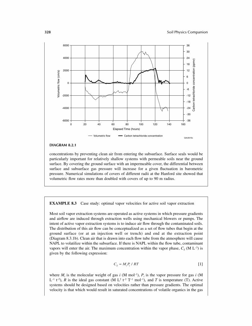
328 Soil Physics Companion
concentrations by preventing clean air from entering the subsurface. Surface seals would beparticularly important for relatively shallow systems with permeable soils near the groundsurface. By covering the ground surface with an impermeable cover, the differential betweensurface and subsurface gas pressure will increase for a given fluctuation in barometricpressure. Numerical simulations of covers of different radii at the Hanford site showed thatvolumetric flow rates more than doubled with covers of up to 90 m radius.
EXAMPLE 8.3 Case study: optimal vapor velocities for active soil vapor extraction
Most soil vapor extraction systems are operated as active systems in which pressure gradientsand airflow are induced through extraction wells using mechanical blowers or pumps. Theintent of active vapor extraction systems is to induce air flow through the contaminated soils.The distribution of this air flow can be conceptualized as a set of flow tubes that begin at theground surface (or at an injection well or trench) and end at the extraction point(Diagram 8.3.1b). Clean air that is drawn into each flow tube from the atmosphere will causeNAPL to volatilize within the subsurface. If there is NAPL within the flow tube, contaminantvapors will enter the air. The maximum concentration within the vapor phase, CS (M L–3) isgiven by the following expression:
[1]
where Mi is the molecular weight of gas i (M mol–1), Pi is the vapor pressure for gas i (ML–1 t–2), R is the ideal gas constant (M L2 t–2 T–1 mol–1), and T is temperature (T). Activesystems should be designed based on velocities rather than pressure gradients. The optimalvelocity is that which would result in saturated concentrations of volatile organics in the gas
DIAGRAM 8.2.1
0 20 40 60 80 100 120 140 160
Elapsed Time (hours)
Vol
umet
ric fl
ow (
cm/s
)
Car
bon
tetr
achl
orid
e co
ncen
trat
ion
(ppm
v)
Volumetric flow Carbon tetrachloride concentration
-6000
-4000
-2000
0
2000
4000
6000
-36
-30
-24
-18
-12
-6
0
6
12
18
24
30
36
QAc9315c
C M P RTS i i= /

Soil Gas Movement in Unsaturated Systems 329
phase at the well. Velocities greater than this optimal velocity would result in greater clean-up costs because more contaminated air would have to be treated. Alternatively, less-than-optimal velocities would result in longer clean-up times. Clean up progresses from the landsurface to the well. The last area to be cleaned is adjacent to the well because the gas becomessaturated near the well; velocities increase near the well.
An estimate of the optimal velocity can be obtained from the following analysis thatconsiders a one-dimensional flow tube (Figure 1a). The actual concentration in the vaporphase will approach the saturated concentration, CS, as the air velocity within a flow tubedecreases. For a flow tube with one-dimensional flow and uniform distribution of NAPL, theratio of the effluent vapor concentration measured at the end of the tube ( ) to thesaturated vapor concentration (equilibrium concentration, CS) is given by the followingexpression (Hines and Maddox, 1985):
[2]
MT* is the mass transfer coefficient (L t–1), a is the contact area between liquid and gas perunit volume (L2 L–3), qG is the volumetric gas content, and u G is the gas velocity. From thisequation one can estimate the velocity required to reach saturation near the well. For mostapplications, the mass transfer coefficient and the contact area are lumped together into aneffective mass transfer coefficient with units of t–1.
Laboratory column experiments can be conducted to estimate the effective mass transfercoefficient, MT* a, by measuring the vapor concentration as a function of flow velocity. If itis assumed that the laboratory-derived transfer coefficient is representative of field-scaleconditions, then Equation [2] can be used to select a velocity in the field based upon the
DIAGRAM 8.3.1 (a) Schematic of active vapor extraction demonstrating change in vapor concentra-tions as vapor moves from land surface to extraction well. (b) Detailed image of single flow tube.
C = 0
L C(x=L)
C = Cs
q(a)
(b)
QAc7318c
q = G G� �
C x L( )=
C
CM aL vx L
S T G G( ) *exp( / )= = - -1 q

330 Soil Physics Companion
lengths of the flow tubes that are developed with the vapor extraction system. The fieldvelocities can be approximated by calculating the flux using Darcy’s law based on headmeasurements at two points and dividing the flux by the volumetric gas content. Gas velocitiesshould be used as the design parameter for active soil vapor extraction systems. Becausepermeabilities can be highly variable, pressure decreases are not that important. Optimalvelocities in one flow tube may not be optimal in another. The pumping rates should becontrolled to achieve maximum saturations at the well.
8.6.2 RADON TRANSPORT
Radon transport has created considerable interest because of the radiological health hazard (lungcancer) associated with the decay products of radon. Radium radioactively decays to radon, andthe greatest doses of radiation result from 222Rn. Many of the issues related to radon transport werereviewed in Nazaroff (1992). Recent evaluations of contaminated sites have focused on risk assess-ment and suggest that one of the most critical exposures to radon and volatile organic contaminantsis from movement of soil gas into buildings. Much research is therefore currently being conductedon gas movement from soil into buildings.
The typical range of radium content in surficial sediments in the United States is 10 to 100 Bqkg–1 (Bq, becquerel is the SI unit for activity, which corresponds to the number of atoms neededto yield a radioactive decay rate of one per second) (Nazaroff, 1992). Much higher concentrationsof radon occur near uranium mines and mill tailings. Radon is also emitted from low-level radio-active waste disposal sites. The half-life of 222Rn is 3.8 days. Radon partitions among solid, liquidand gas phases. Diffusive transport is sufficient to account for radon migration from unsaturatedmaterial into the atmosphere. Radon fluxes estimated on the basis of diffusion are consistent withexperimental measurement (Nazaroff, 1992). The diffusion coefficient of 222Rn in air is 1.2 ¥ 10–5
m2 s–1 (Hirst and Harrison, 1939). The effective diffusion coefficient, including the effect of reducedcross-sectional area and increased path length (tortuosity), is about a factor of four smaller thanthe free air diffusion coefficient in fairly dry soils (Nazaroff, 1992). Effective diffusivities insaturated systems are about four orders of magnitude less than those in dry soils (Tanner, 1964).This difference has been used in the design of engineered barriers for uranium mill tailings tominimize upward movement of radon into the atmosphere. Thick clay layers (0.6 to 2 m) are usedas radon barriers because they retain much more water than does sand and thus reduce radondiffusion. Desiccation of clay, however, results in cracking and development of preferred pathwaysfor gas transport. Typical diffusive fluxes for radon estimated by Nazaroff (1992) average 0.022Bq m–2 s–1, which is the same average as diffusive fluxes in Australian soils estimated by Scheryet al. (1989).
Advection is generally considered more important than diffusion for radon transport intobuildings because concrete slabs provide a barrier to diffusion and ventilation causes a pressuredifferential between indoor and outdoor air that drives advective gas transport. Advective gastransport, described by Darcy’s law, varies with permeability and pressure gradient. Becausepermeability generally decreases with grain size, Nazaroff and Sextro (1989) suggested that diffu-sion is dominant in low permeability materials and advection dominant in high permeability materials,the cutoff being ~ 10–11 m2. Gas permeability is generally anisotropic because sediment layering resultsin higher permeabilities horizontally than vertically. Openings in the substructures of buildings providepathways for advective radon transport into buildings. The average indoor 222Rn concentration inbuildings is 50 Bq m–3; in soil, ~ 30 Bq m–3 (Nazaroff, 1992). Pressure differentials across buildingsmay result from ventilation caused by open windows and doors, fans, heating and air conditioning.Heating generally increases radon entry into buildings; air conditioning reduces it.
The construction of building substructures can have important implications for advective gastransport. Concrete slabs are commonly underlain by gravel layers. Penetrations at floor wall joints

Soil Gas Movement in Unsaturated Systems 331
and perimeter drain systems allow gas transport. Temperature differences, barometric pressurefluctuations, wind and rain cause pressure differentials (Nazaroff, 1992).
Diffusive fluxes can account for about 10% of mean radon concentration in single familydwellings (Nero et al., 1986). Nazaroff (1992) presented several different paradigms for radon entryinto dwellings. In the base case, transport of radon from the soil into buildings is attributed primarilyto advective airflow driven by weather and ventilation. An alternative paradigm would be soil withstrongly varying permeability, in which case diffusion would be important for transporting gas fromhigh- to low-permeability regions, such as gravel seams or cracked clays. Another alternative is ahigh-permeability material at the interface between the building and the soil, such as a gravel layer ora thin air gap. In this case, molecular diffusion from the native low-permeability soil to the high-permeability gravel is important, and advection alone would result in much slower transport of radon.
8.6.3 WATER VAPOR DIFFUSION
Analysis of water vapor transport in natural systems can be done by approximating soil gas as atwo-component system containing water vapor and air. Diffusion of water vapor is important innear-surface sediments where evaporation is occurring and in arid systems where water contentsare extremely low. The simple theory of water vapor diffusion assumes that water vapor behaveslike other gases. The flux of water vapor (water in the gas phase) is:
[8.57]
where is the binary diffusion coefficient for water vapor in air and is the water vapor density.The Kelvin equation can be used to express water vapor density in terms of temperature and matricpotential head:
[8.58]
where is saturated vapor density, RH is relative humidity, hm is matric potential (Pa), Vw is themolar volume of water (1.8 ¥ 10–5 m3 mol–1), R is the gas constant and T is Kelvin temperature.Laboratory experiments showed that water vapor fluxes estimated by Equation [8.58] underesti-mated measured water vapor fluxes by as much as one order of magnitude. Philip and de Vries(1957) attributed the discrepancy between laboratory measured and estimated water vapor fluxesto (1) liquid island enhancements and (2) increased temperature gradients in the air phase. Liquidisland enhancement refers to the fact that when the liquid phase is discontinuous, liquid islandsact as short circuits for thermal vapor diffusion. Water vapor condenses on one side of liquid waterand evaporates on the other side. This results in an increased cross-sectional area for diffusion fromthe volumetric gas content to the sum of the volumetric gas and liquid contents (porosity) whenthe water phase is discontinuous. Temperature gradients in the gas phase are much higher than theaverage temperature gradients in porous media because thermal conductivity in the gas phase ismuch lower than that in the liquid and solid phases:
[8.59]
where is the average temperature gradient in the gas phase, is the average bulk temperaturegradient in the system, and f is a correction factor for liquid island enhancement and is equal tothe porosity when the liquid phase is discontinuous (Milly and Eagleson, 1980). Thermal vapor
q DGw
G Gw
v= - �q t r
DGw rv
r r rrv v v
m w
w
RHh V
RT= ◊ =0 0 exp
rv0
q D fT
TD
TTG
wG G G
w gw
T
GG G
w v= -∂∂
� -��
∂∂
�q try
y tr
y
�TG �T

332 Soil Physics Companion
flux, resulting from variations in saturated vapor pressure with temperature, is generally consideredmuch more important than isothermal vapor flux. A temperature difference of 1°C at 20°C resultsin a greater difference in vapor density (1.04 ¥ 10–3 kg m–3) than does a 1.5 MPa difference inmatric potentials from –0.01 to –1.5 MPa (0.17 ¥ 10–3 kg m–3) (Hanks, 1992). The temperaturedependence of saturated vapor pressure is given in Table 8.1. Temperature gradients are generallyhigh in near surface sediments, and nonisothermal vapor diffusion is important.
One-dimensional liquid and vapor transport in arid and semiarid systems has been simulatedby two-phase (liquid and gas), single-component (water), nonisothermal codes (BREATH, SPLaSH-WaTr, UNSAT-H) (Stothoff, 1995; Milly, 1982; Fayer and Jones, 1990). Advective gas transportis not included. In many applications of these codes, liquid and vapor flow is simulated in responseto atmospheric forcing functions. Mass and energy equations are solved sequentially, and theresultant tridiagonal equations are readily solved by the efficient Thomas algorithm. These simu-lators solve the continuity equation for water:
[8.60]
where is the density of water in the liquid phase and is the density of water vapor in thegas phase. Darcy’s law is used to solve the liquid water flux, and the theory of Philip and de Vries(1957) is used to solve the vapor diffusive flux. The energy balance equation is also solved in thesecodes. Numerical simulations of liquid and vapor flux provide insights on flow processes in theunsaturated zone. Simulations in response to 1 yr of atmospheric forcing in the Chihuahuan Desertof Texas showed net downward water flux in response to seasonally varying temperature gradientsthat was consistent with isotopic tracer data (Scanlon and Milly, 1994). Simulations at YuccaMountain, Nevada, evaluated the impact of hydraulic properties on infiltration (Stothoff, 1997).For low permeabilities in this system, vapor transport was dominant. The simulations demonstratedthe importance of the alluvial cover on fractured bedrock in decreasing downward water flux. TheUNSAT-H code was used to evaluate the performance of engineered barriers, including a capillarybarrier at the Hanford site (Fayer et al., 1992). Hysteresis was found to be important in reproducingdrainage measured through the capillary barrier.
8.6.4 PREFERENTIAL FLOW
Preferential flow refers to nonuniform movement of a fluid. In most cases preferential flow hasbeen examined with respect to water flow. Preferential flow can occur in macropores that arenoncapillary size pores, such as desiccation cracks in clays, worm holes and root tubules in soils,and fractures in rocks. Because macropores drain rapidly they are generally dry, and preferentialflow of gases should therefore be much greater than that of liquids.
There has been much interest in fractured systems in recent years because the proposed highlevel radioactive waste disposal facility is located in fractured tuff. Fractures allow rapid transportof contaminants in unsaturated systems. The cubic law is used to describe fracture flow, which isproportional to the fracture aperture cubed for a given head gradient. Laminar flow between smoothparallel plates is given by:
[8.61]
where Q is the volumetric flow rate (L3 t–1), b is aperture opening (L), w is the width of the fractureperpendicular to the direction of flow (L), bw is the cross-sectional area (L2) and P is the hydraulichead (Pa) (Snow, 1968). Fractures are important because they account for most of the permeability
∂∂
r q r q r rt
q qlw
l Gv
G lw
l Gv
v+( ) = -� ◊ +( )
rlw rG
v
Q Aq bwb P
z
b w P
zGG G
= = =( )2 3
12 12m∂∂ m
∂∂
Soil Gas Movement in Unsaturated Systems 333
in the system, whereas the matrix is important because it accounts for most of the porosity. Nilsonet al. (1991) evaluated contaminant gas transport in fractured permeable systems. For example, asystem that has 1 mm wide fractures ( ) separated by 1 m slabs of matrix ( ) with a matrixporosity of 0.10 (fm) will have a ratio of capacitance volumes (V) as follows (Nilson et al., 1991):
[8.62]
Most mass flow occurs through the fractures as shown by the following (Nilson et al., 1991):
[8.63]
where Q is the mass flow, q is the mass flux density, and km is the gas permeability of the matrix(10–15 m2). Even with high matrix permeability (~ 10–12 m2) and narrow fractures (10–4 m), about99% of the flow will occur in the fractures.
In fractured, permeable media, advective fluxes resulting from barometric pressure fluctuationsmay be orders of magnitude greater than diffusive fluxes and could result in upward movement ofcontaminated gases into the atmosphere (Nilson et al., 1991). Theoretical analyses by Nilson et al.(1991) showed that in homogeneous media, a differential barometric pressure fluctuation of 7%(DP/P0) would result in the upward movement of an interface between contaminated and pure gasof 20 m if the interface were 300 m deep. In contrast, in fractured systems the volume expansionof the gas is the same as that in porous media; however, gas expansion occurs primarily in thefractures and the interface moves as much as two orders of magnitude higher in the system. Theconceptual model developed for upward movement of contaminants involves upward gas movementin the fractures as a result of barometric pressure fluctuations and lateral diffusion from the fracturesinto the surrounding matrix, which holds the contaminants at that level until the next barometricpressure fluctuation. This is a racheting mechanism for transporting gases upward. A gas tracerexperiment conducted by Nilson et al. (1992) confirmed the results of earlier theoretical analyses.These experiments showed upward movement of gas tracers in a period of months from a sphericalcavity (depth ~300 m) created by underground nuclear tests at the Nevada Test Site. This rapidupward movement of gases was attributed to the effects of barometric pumping in fractured tuff.
Weeks (1987; 1993) also conducted detailed studies of flow in fractured tuff at Yucca Mountain.In areas of steep topography such as at Yucca Mountain, temperature and density-driven topographiceffects result in continuous exhalation of air through open boreholes at the mountain crest in thewinter, as cold dry air from the flanks of the mountain replaces warm moist air within therock/borehole system (Weeks, 1987). Wind also results in air discharge from the boreholes that isabout 60% of that resulting from temperature induced density differences (Weeks, 1993). Openboreholes greatly enhance the advective air flow at this site; numerical simulations indicate thatwater fluxes resulting from advective air flow under natural conditions (0.04 mm yr–1) are fiveorders of magnitude less than those found in the borehole (Kipp, 1987) and similar in magnitudeto estimated vapor fluxes as a result of the geothermal gradient (0.025 to 0.05 mm yr–1; Montazeret al., 1985). These processes could cause drying of fractured rock uplands and could expedite therelease of gases from underground repositories to the atmosphere (Weeks, 1993).
UNITS
Pressure: 1 atm. = 760.0 mm Hg = 101.325 kPa = 1.01 bars = 10.2 m H20Permeability: 1 darcy = 9.87 ¥ 10–13 m2
Viscosity: 1 Pa s = 1,000 cp
d f dm
V
Vm
f
m m
f
= f dd
~ 100
Q
Q
A q
A q k kf
m
f f
m m
f
m
f
m
f
m m
=( )
~/
~ ~dd
d dd
2 35
12 112
10

334 Soil Physics Companion
8.7 DERIVATION OF EQUATIONS
Derivation of Equation [8.30]:
[8.64; 8.29]
Assuming f is constant and writing gas density in terms of pressure (Equation [8.17]):
[8.65]
The term M/RT is constant and can be canceled:
[8.66]
Assuming permeability and viscosity are constant:
[8.67]
[8.68; 8.30]
Equation [8.69] is Equation [8.30] in Section 8.2.2. The derivation assumes single-phase flow.Similar expressions can be developed for two-phase flow (air and water) by using the volumetricgas content instead of porosity.
Equation [8.31] is derived by assuming that the pressure fluctuations are small, an assumptionsatisfied in many cases in the unsaturated zone:
[8.69]
The first term on the right of Equation [8.70] is a constant; therefore, its derivative is zero. Thethird term is negligible and is neglected. Equation [8.30] can be converted to Equation [8.31] usingthe following:
[8.70]
[8.71; 8.31]
∂r f∂
rm
G G G
Gt
kP= -� ◊ - �
Ê
ËÁ��̄
f∂
∂ m
PM
RTt
PM
RTk
PG
G
= � ◊ �
Ê
Ë
ÁÁÁ
�
¯
���
M
RT
P
t
M
RT
PkPG
G
f ∂∂ m
= � ◊ �Ê
ËÁ��̄
f ∂∂ m
2 2PP
t
kP P PG
G
= � ◊ �( )
∂∂ fmP
t
k PPG
G
20 2 2ª �
( )qG
P P P
P P PP P
= +
= + + ( )
0
202
022
D
D D
∂∂
∂∂
P
tP
P
t
2
02=
� = �
= �
2 20
2
2
2P P P
P
tP
∂∂
a

Soil Gas Movement in Unsaturated Systems 335
Derivation of the form of equations (Section 8.1.6.3) for a binary gas mixture is shown in thefollowing. Diffusive transport of nonequimolar gases in an isobaric system mixture is describedby (Cunningham and Williams, 1980):
[8.72]
The molar diffusive flux of component i ( ) results from the molecular diffusive flux ( ) andthe nonequimolar diffusive flux ( ) of gas component i. Because the nonequimolar diffusive fluxis nonsegregative, the contribution of each species is proportional to its mole fraction xi andEquation [8.72] can be reformulated:
[8.73]
[8.74]
Because , it can be proved that ; Equation [8.74] can be rewritten as:
[8.75]
If Equation [8.73] is applied to the two components A and B of an isobaric, binary mixture,Equation [8.74] becomes:
[8.76]
[8.77]
where nAM and nBM are the number of moles of gases A and B. Because the system is isobaric, thetotal flux is zero (otherwise a pressure gradient would result), and Equations [8.76] and [8.77]reduce to Fick’s law applied to the total diffusive flux. This is the only case when Fick’s law isstrictly valid. In deriving Equations [8.76] and [8.77], the segregative diffusive flux is assumed tofollow a gradient law:
[8.78]
The following two equations result:
[8.79]
[8.80]
Multiplying Equation [8.79] with xB and [8.80] with xA results in:
[8.81]
[8.82]
N J NiD
iMm
iN= +
NiD JiM
m
NiN
N J x NiD
iMm
iN= +
N J x NiD
i
v
iMm
i
v
i
i
vN
= = =Â Â Â= +
Ê
ËÁ
�
¯�
1 1 1
xi
i
v
==
 11
JiMm
i
v
=Â =
1
0
N NiD
i
vN
=Â =
1
N D n x N NAD
AB AM A AD
BD= - � + +( )
N D n x N NBD
BA BM B AD
BD= - � + +( )
J D nAMm
AB A M= - �
N D n x N NAD
AB AM A AD
BD= - � + +( )
N D n x N NBD
BA BM B AD
BD= - � + +( )
x N x D n x x N NB AD
B AB AM A B AD
BD= - � + +( )
x N x D n x x N NA BD
A BA BM A B AD
BD= - � + +( )

336 Soil Physics Companion
Subtracting Equation [8.82] from Equation [8.81] results in:
[8.83]
Because constant and , Equation [8.83] can be rewritten as:
[8.84]
According to the ideal gas law ; therefore:
[8.85]
REFERENCES
Abriola, L.M., C.S. Fen, and H.W. Reeves. 1992. Numerical simulation of unsteady organic vapor transportin porous media using the dusty gas model, 195–202, in Proc. of the Int. Assoc. Hydrol. Conf. onSubsurface Contamination by Immiscible Fluids, A.A. Balkema, Rotterdam, Netherlands.
Abu-El-Sha’r, W.Y. 1993. Experimental Assessment of Multicomponent Gas Transport Mechanisms in Sub-surface Systems, Ph.D. dissertation, 75, Univ. of Mich., Ann Arbor.
Abu-El-Sha’r, W.Y. and L.M. Abriola. 1997. Experimental Assessment of Gas Transport Mechanisms in NaturalPorous Media: Parameter Evaluation, Water Resour. Res., 33:505–516.
Alzaydi, A.A. 1975. Flow of Gases through Porous Media, 172 pp., Ohio State University, Columbus.Alzaydi, A.A. and C.A. Moore. 1978. Combined pressure and diffusional transition region flow of gases in
porous media, AICHE J., 24(1):35–43.Amali, S. and D.E. Rolston. 1993. Theoretical investigation of multicomponent volatile organic vapor diffusion:
steady-state fluxes, J. Environ. Qual., 22:825–831.Amali, S., D.E. Rolston, and T. Yamaguchi. 1996. Transient multicomponent gas-phase transport of volatile
organic chemicals in porous media, J. Environ. Qual., 25:1041–1047.Auer, L.H., N.D. Rosenberg, K.H. Birdsell, and E.M. Whitney. 1996. The effects of barometric pumping on
contaminant transport, J. Contam. Hydrol., 24:145–166.Baehr, A.L. and C.J. Bruell. 1990. Application of the Stefan-Maxwell equations to determine limitations of
Fick’s law when modeling organic vapor transport in sand columns, Water Resour. Res., 26:1155–1163.Baehr, A.L., G.E. Hoag, and M.C. Marley. 1989. Removing volatile contaminants from the unsaturated zone
by inducing advective air-phase transport, J. Contam. Hydrol., 4:1–26.Baehr, A.L. and M.F. Hult. 1991. Evaluation of unsaturated zone air permeability through pneumatic tests,
Water Resour. Res., 27:2605–2617.Benson, D.A., D. Huntley, and P.C. Johnson. 1993. Modeling vapor extraction and general transport in the
presence of NAPL mixtures and nonideal conditions, Ground Water, 31(3):437–445.Bird, R.B., W.E. Stewart, and E.N. Lightfoot. 1960. Transport Phenomena, 780 pp., John Wiley, NY.Brooks, R.H. and A.T. Corey. 1964. Hydraulic Properties of Porous Media, 27 pp., Colorado State Univ.
Hydrology Paper No. 3.Brusseau, M.L. 1994. Transport of reactive contaminants in heterogeneous porous media, Rev. Geophys.,
32:285–313.Buckley, S.E. and M.C. Leverett. 1942. Mechanisms of fluid displacement in sands, Trans. Am. Inst. Mining
Metallurgical Engineers, 146:107–116.
x N x N D x n x nB AD
A BD
AB B AM A BM- = - � - �( )
n n nAM BM+ = = x xA B+ = 1
x N x N D x n x n
x N x N D n x n n
x N x N D n
B AD
A BD
AB A AM A BM
B AD
A BD
AB AM A AM BM
B AD
A BD
AB AM
- = - - � - �( )- = - � - � +( )- = - �
( ) ( )
( )
1
Pn
RTAAM=
x N x N
D
P
RTB A
DA B
D
AB
A-= -
�

Soil Gas Movement in Unsaturated Systems 337
Burdine, N.T. 1953. Relative permeability calculations from pore size distribution data, Petr. Trans., AIME,198:71–78.
Carslaw, H.S. and J.C. Jaeger. 1959. The Conduction of Heat in Solids, 510 pp., Oxford Univ. Press, London.Celia, M.A. and P. Binning. 1992. A mass conservative numerical solution for two-phase flow in porous media
with application to unsaturated flow, Water Resour. Res., 28:2819–2828.Charbeneau, R.J. and D.E. Daniel. 1992. Contaminant transport in unsaturated flow, 15.1–15.54, in Handbook
of Hydrology, D.R. Maidment, (ed.), McGraw-Hill, Inc., NY.Childs, S.W. and G. Malstaff. 1982. Heat and Mass Transfer in Unsaturated Porous Media, 173, Pacific
Northwest Laboratory.Collins, R.E. 1961. Flow of Fluids through Porous Media, 270 pp., van Nostrand-Reinhold, Princeton, NJ.Connor, J.R. 1988. Case study of soil venting, Pollution Engr., 20(7):74–78.Corey, A.T. 1954. The interrelation between gas and oil relative permeabilities, Producer’s Monthly,
19(1):38–44.Corey, A.T. 1986. Air permeability, 1121–1136, in A. Klute (ed.), Methods of Soil Analysis, Am. Soc. Agron.,
Madison, Wisconsin.Croise, J. and V. Kaleris. 1992. Field measurements and numerical simulations of pressure drop during air
stripping in the vadose zone, in K.U. Weger (ed.), Subsurface Contamination by Immiscible Fluids,A.A. Balkema, Rotterdam.
Cunningham, R.E. and R.J.J. Williams. 1980. Diffusion of Gases and Porous Media, 275 pp., Plenum, NY.Demond, A.H. and P.V. Roberts. 1987. An examination of relative permeability relations for two-phase flow
in porous media, Water Resour. Bull., 23(4):617–628.Detty, T.E. 1992. Determination of Air and Water Relative Permeability Relationships for Selected Unconsol-
idated Porous Materials, Ph.D. dissertation, 194 pp., Univ. Ariz., Tucson.Duffield, G.M. and J.O. Rumbaugh, 1989. AQTESOLV aquifer test solver documentation; version 1.00,
Geraghty and Miller Modeling Group, Reston, VA.Dullien, F.A.L. 1979. Porous Media: Fluid Transport and Pore Structure, 396 pp., Academic Press, NY.Edwards, K.B. 1994. Air permeability from pneumatic tests in oxidized till, J. Environ. Eng., 120(2):329–346.Ellerd, M., J.W. Massmann, D.P. Schwaegler, and V.J. Rohay. 1999. Enhancements for passive vapor extraction:
the Hanford study, Ground Water, Vol. 37, 427–437.Estes, R.K. and P.F. Fulton. 1956. Gas slippage and permeability measurements, Trans. Am. Inst. Min. Metall.
Pet. Eng., 207:338–342.Falta, R.W. 1995. Analytical solutions for gas flow due to gas injection and extraction from horizontal wells,
Ground Water, 33(2):235–246.Falta, R.W., I. Javandel, K. Pruess, and P.A. Witherspoon. 1989. Density-driven flow of gas in the unsaturated
zone due to the evaporation of volatile organic compounds, Water Resour. Res., 25:2159–2169.Falta, R.W., K. Pruess, and D.A. Chesnut. 1993. Modeling advective contaminant transport during soil vapor
extraction, Ground Water, 31(6):1011–1020.Fayer, M.J. and T.L. Jones. 1990. UNSAT-H Version 2.0: Unsaturated soil water and heat flow model, Pac.
Northwest Lab., Richland, WA.Fayer, M.J., M.L. Rockhold, and M.D. Campbell. 1992. Hydrologic modeling of protective barriers: compar-
ison of field data and simulation results, Soil Sci. Soc. Am. J., 56:690–700.Finsterle, S. and K. Pruess. 1995. Solving the estimation-identification problem in two-phase flow modeling,
Water Resour. Res., 31(4):913–924.Forcheimer, P. 1901. Wasserbewegung durch boden, Zeitschrift Des Verines Deutch Ing, 49:1736–1749.Freeze, R.A. and J.A. Cherry. 1979. Groundwater, 604, Prentice Hall, NJ.Gardner, W.H. 1986. Water content, 493–545, in A. Klute (ed.), Methods of Soil Analysis, Part 1, Physical
and Mineralogical Methods, Monograph 9, Am. Soc. Agron., Madison, Wisconsin.Gierke, J.S., N.J. Hutzler, and D.B. McKenzie. 1992. Vapor transport in unsaturated soil columns: Implications
for vapor extraction, Water Resour. Res., 28(2):323–335.Glauz, R.D. and D.E. Rolston. 1989. Optimal design of two-chamber, gas diffusion cells, Soil Sci. Soc. Am.
J., 53:1619–1624.Goggin, D.J., R.L. Thrasher, and L.W. Lake. 1988. A theoretical and experimental analysis of minipermeameter
response including gas slippage and high velocity flow effects, In Situ, 12:79–116.Hampton, D. 1989. Coupled heat and fluid flow in saturated-unsaturated compressible porous media, 293 pp.,
Colorado State University, Fort Collins, CO.

338 Soil Physics Companion
Hanks, R.J., 1992. Applied Soil Physics, 176 pp., Springer-Verlag, NY.Hassler, G.L. 1944. Method and apparatus for permeability measurements, Patent Number 2,345,935 April 2,
1944, U.S. Patent Office, Washington, DC.Hayden, N.J., T.C. Voice, M.D. Annable, and R.B. Wallace. 1994. Change in gasoline constituent mass transfer
during soil venting, J. Environ. Eng., 120:1598–1614.Hazen, A. 1911. Discussion: dams on sand foundations, Trans. Am. Soc. Civ. Eng., 73:199.Heid, J.G., J.J. McMahon, R.F. Nielsen, and S.T. Yuster. 1950. Study of the permeability of rocks to homo-
geneous fluids, in A.P.I. Drilling and Production Practice, 230, A.P.I.Hirst, W. and G.E. Harrison. 1939. The diffusion of radon gas mixtures, Proc. R. Soc. London, Ser. A,
169:573–586.Hines, A.L. and R.N. Maddox. 1985. Mass Transfer: Fundamentals and Applications, 529 pp., Prentice Hall,
Englewood Cliffs, NJ.Hoag, G.E. and M.C. Marley. 1986. Gasoline residual saturation in unsaturated uniform aquifer materials, J.
Environ. Eng., 112(3):586–604.Hutzler, N.J., B.E. Murphy, and J.S. Gierke. 1989. State of technology review: soil vapor extraction systems,
Final Report to U.S. EPA, 36 pp., Hazardous Waste Engineering Research Laboratory.Jackson, R. 1977. Transport in Porous Catalysts, Elsevier Science Publ. Co., NY.Jaynes, D.B. and A.S. Rogowski. 1983. Applicability of Fick’s law to gas diffusion, Soil Sci. Soc. Am. J.,
47:425–430.Jin, M., M. Delshad, B. Dwarakanath, D.C. McKinney, G.A. Pope, K. Sepehrnoori, C. Tilburg, and R.E.
Jackson. 1995. Partitioning tracer test for detection, estimation, and remediation performance assess-ment of subsurface nonaqueous phase liquids, Water Resour. Res., 31:1201–1211.
Johnson, P.C., A.L. Baehr, R.A. Brown, R.E. Hinchee, and G.E. Hoag. 1995. Innovative Site RemediationTechnology: Vol. 8 – Vacuum Vapor Extraction, American Academy of Environmental Engineers,Annapolis.
Johnson, P.C., M.W. Kemblowski, and J.D. Colthart. 1990a. Quantitative analysis for the cleanup of hydro-carbon-contaminated soils by in situ soil venting, Ground Water, 28(3):413–429.
Johnson, P.C., C.C. Stanley, M.W. Kemblowski, D.L. Byers, and J.D. Colthart. 1990b. A practical approachto the design, operation, and monitoring of in situ soil-venting systems, Ground Water Monit. Rev.,10(2):159–178.
Joss, C.J. and A.L. Baehr. 1995. Documentation of AIR3D, an adaptation of the ground water flow codeMODFLOW to simulate three-dimensional air flow in the unsaturated zone, in U.S. Geol. Surv. OpenFile Rept. 94-533, 154 pp., U.S. Geol. Survey.
Joss, C.J. and A.L. Baehr 1997. AIR2D — A computer code to simulate two-dimensional, radially symmetricairflow in the unsaturated zone, in U.S. Geological Survey Open File Report 97-588, 106, U.S.Geological Survey.
Jury, W.A., W.R. Gardner, and W.H. Gardner. 1991. Soil Physics, 328 pp., John Wiley & Sons, Inc., NY.Kaluarachchi, J.J. 1995. Analytical solution to two-dimensional axisymmetric gas flow with Klinkenberg
effect, J. Envir. Eng., 121(5):417–420.Kaluarachchi, J.J. and J.C. Parker. 1989. An efficient finite element method for modeling multiphase flow,
Water Resources Research, 25(1):43–54.Kipp, K.L.J. 1987. Effect of topography on gas flow in unsaturated fractured rock: Numerical simulation,
171–176, in D.D. Evans and T.J. Nicholson (eds.), Flow and Transport Through Unsaturated FracturedRock, Geophys. Monog. 9, Am. Geophys. Union, Washington, DC.
Klinkenberg, L.J. 1941. The permeability of porous media to liquids and gases, 200 pp., A.P.I. Drilling andProduction Practice.
Kreamer, D.K., E.P. Weeks, and G.M. Thompson. 1988. A field technique to measure the tortuosity andsorption-affected porosity for gaseous diffusion of materials in the unsaturated zone with experimentalresults from near Barnwell, South Carolina, Water Resour. Res., 24:331–341.
Lai, S.H., J.M. Tiedje, and A.E. Erickson. 1976. In situ measurement of gas diffusion coefficient in soils, SoilSci. Soc. Am. J., 40:3–6.
Leffelaar, P.A. 1987. Dynamic simulation of multinary diffusion problems related to soil, Soil Sci., 143:79–91.Marshall, T.J. 1958. A relation between permeability and size distribution of pores, J. Soil Sci., 9:1–8.Mason, E.A. and A.P. Malinauskas. 1983. Gas transport in porous media: the Dusty-Gas Model, in Chem.
Engr. Monogr., Vol. 17, 194, Elsevier, NY.

Soil Gas Movement in Unsaturated Systems 339
Mason, E.A., A.P. Malinauskas, and R.B. Evans. 1967. Flow and diffusion of gases in porous media, J. Chem.Phys., 46:3199–3126.
Massmann, J.W. 1989. Applying groundwater flow models in vapor extraction system design, J. Env. Engin.,115:129–149.
Massmann, J. and D.F. Farrier. 1992. Effects of atmospheric pressures on gas transport in the vadose zone,Water Resour. Res., 28:777–791.
Massmann, J.W. and M. Madden. 1994. Estimating air conductivity and porosity from vadose-zone pumpingtests, J. Env. Eng., 120(2):313–328.
McClellan, R.D. and R.W. Gillham. 1992. Vapour extraction of trichloroethylene under controlled conditionsat the Borden site, in Subsurface Contamination by Immiscible Fluids, 89–96, A.A. Balkema, Rot-terdam.
McDonald, M.G. and A.W. Harbaugh. 1988. A modular three-dimensional finite-difference ground-water flowmodel, in Techniques of Water Resources Investigations, 576 pp., USGS.
McIntyre, D.S. and J.R. Philip. 1964. A field method for measurement of gas diffusion into soils, Aust. J. SoilRes., 2:133–145.
McWhorter, D.B. 1990. Unsteady radial flow of gas in the vadose zone, J. Contam. Hydrol., 5:297–314.Mendoza, C.A. and E.O. Frind. 1990. Advective-dispersive transport of dense organic vapors in the unsaturated
zone: Sensitivity analysis, Water Resour. Res., 26(3):388–398.Mendoza, C.A. and T.A. McAlary. 1990. Modeling of ground-water contamination caused by organic solvent
vapors, Ground Water, 28(2):199–206.Mercer, J.W. and R.M. Cohen. 1990. A review of immiscible fluids in the subsurface: properties, models,
characterization, and remediation, J. Contam. Hydrol., 6(2):107–163.Millington, R.J. 1959. Gas diffusion in porous media, Science, 130:100–102.Millington, R.J. and J.P. Quirk. 1961. Permeability of porous solids, Faraday Soc. Trans., 57(7):1200–1207.Millington, R.J. and R.C. Shearer. 1970. Diffusion in aggregated porous media, Soil Sci., 3(6):372–378.Milly, P.C.D. 1982. Moisture and heat transport in hysteretic, inhomogeneous porous media: a matric head-
based formulation and a numerical model, Water Resour. Res., 18:489–498.Milly, P.C.D. and P.S. Eagleson. 1980. The coupled transport of water and heat in a vertical soil column under
atmospheric excitation, 234, Ralph M. Parsons Lab., Mass. Inst. Technol.Montazer, P., E.P. Weeks, F. Thamir, S.N. Yard, and P.B. Hofrichter. 1985. Monitoring the vadose zone in
fractured tuff, Yucca Mountain, Nevada, 439–469, in Proc. on Characterization and Monitoring ofthe Vadose (Unsaturated) Zone, National Water Well Association, Denver.
Moore, C., I.S. Rai, and J. Lynch. 1982. Computer design of landfill methane migration control, J. Env. Eng.Div. Am. Soc. Civ. Eng., 108:89–107.
Morel-Seytoux, H.J. 1973. Two-phase flow in porous media, Adv. Hydrosci., 9:119–202.Morel-Seytoux, H.J. and J.A. Billica. 1985. A two-phase numerical model for prediction of infiltration:
Application to a semi-infinite column, Water Resour. Res., 21(4):607–615.Mualem, Y. 1976. A new model for predicting the hydraulic conductivity of unsaturated porous media, Water
Resour. Res., 12(3):513–521.Muskat, M. 1946. Flow through Porous Media, 72 pp., McGraw Hill, NY.Nazaroff, W.W. 1992. Radon transport from soil to air, Rev. Geophys., 30:137–160.Nazaroff, W.W. and R.G. Sextro. 1989. Technique for measuring the indoor 222Rn source potential of soil,
Environ. Sci. Technol., 23:451–458.Nero, A.V., A.J. Gadgil, W.W. Nazaroff, and K.L. Revzan. 1986. Distribution of airborne radon-222 concen-
trations in U.S. homes, Science, 234:992–997.Nicot, J.P. 1995. Characterization of gas transport in a playa subsurface Pantex Site, Amarillo, Texas, Master’s
thesis, 178 pp., The University Texas at Austin.Nilson, R.H., W.B. McKinnis, P.L. Lagus, J.R. Hearst, N.R. Burkhard, and C.F. Smith. 1992. Field measure-
ments of tracer gas transport induced by barometric pumping, 710–716, in Proc. of the Third Inter-national Conference of High Level Radioactive Waste Management, Am. Nucl. Soc.
Nilson, R.H., E.W. Peterson, K.H. Lie, N.R. Burkard, and J.R. Hearst. 1991. Atmospheric pumping: amechanism causing vertical transport of contaminated gases through fractured permeable media, J.Geophys. Res., 96(B13):21933–21948.
NRC. 1996. Rock Fractures and Fluid Flow Contemporary Understanding and Applications, 551 pp., NationalAcademy Press, Washington, DC.

340 Soil Physics Companion
Pederson, T.A. and J.T. Curtis. 1991. Soil Vapor Extraction Technology — Reference Handbook, Office ofResearch and Development.
Penman, H.L. 1940a. Gas and vapor movements in the soil. I. The diffusion of vapors through porous solids,J. Agr. Sci., 30:437–462.
Penman, H.L. 1940b. Gas and vapor movements in the soil. II. The diffusion of carbon dioxide through poroussolids, J. Agr. Sci., 30:570–581.
Pfannnkuch, H. 1983. Hydrocarbon spills, their retention in the subsurface and propagation into shallowaquifers, Office Water Resources Technology, 51 pp., Office of Water Resources Technology, Wash-ington, DC.
Philip, J.R. and D.A. de Vries. 1957. Moisture movement in porous materials under temperature gradients,Trans. AGU, 38:222–232.
Pruess, K. 1987. TOUGH User’s Guide, NUREG/CR-4645, 78, Nuclear Regulatory Commission, Washington,DC.
Pruess, K. 1991. TOUGH2 — A general-purpose numerical simulator for multiphase fluid and heat flow,Lawrence Berkeley Lab., Berkeley, CA.
Pruess, K. and T.N. Narasimhan, 1985. A practical method for modeling fluid and heat flow in fractured porousmedia, Soc. Petrol. Engin. J., 25:14–26.
Pruess, K., J.S.Y. Wang, and Y.W. Tsang. 1990. On thermohydrologic conditions near high-level nuclear wastesemplaced in partially saturated fractured tuff, 1, simulation studies with explicit consideration offracture effects, Water Resour. Res., 26:1235–1248.
Raney, W.A. 1949. Field measurement of oxygen diffusion through soil, Soil Sci. Soc. Am. Proc., 14:61–65.Rathfelder, K., J.R. Lang, and L.M. Abriola. 1995. Soil vapor extraction and bioventing: Applications,
limitations, and future research directions, U.S. Natl. Rep. Int. Union Geod. Geophys. 1991–1994,Rev. Geophys., 33:1067–1081.
Rathfelder, K., W.W.-G. Yeh, and D. Mackay. 1991. Mathematical simulation of soil vapor extraction systems:model development and numerical examples, J. Contam. Hydrol., 8:263–297.
Rohay, V.J. 1996. Field tests of passive soil vapor extraction at the Hanford Site, Washington, BHI-00766,Rev. 0, Bechtel Hanford, Inc., Richland, WA.
Rojstaczer, S. and J.P. Tunks. 1995. Field-based determination of air diffusivity using soil-air and atmosphericpressure time series, Water Resour. Res., 12:3337–3343.
Rolston, D.E.. 1986. Gas diffusivity, 1089–1102, in A. Klute (ed.), Methods of Soil Analysis, Vol. 1, Am. Soc.Agron., Madison, Wisconsin.
Rolston, D.E., D. Kirkham, and D.R. Nielsen. 1969. Miscible displacement of gases through soils columns,Soil Sci. Soc. Am. Proc., 33:488–492.
Rosenberg, N.D., Soll, W.E., and Zyvoloski, G.A. 1994. Microscale and macroscale modeling of flow inunsaturated fractured rock: Am. Geophys. Union, Chapman Conf. on Aqueous Phase and MultiphaseTransport in Fractured Rock, 22 pp., Sept. 12–15, Burlington, VT.
Satterfield, C.N. and P.J. Cadle. 1968. Diffusion and flow in commercial catalysts at pressure levels aboutatmospheric, J. Ind. Eng. Chem. Fundamentals, 7:202.
Scanlon, B.R. and P.C.D. Milly. 1994. Water and heat fluxes in desert soils 2. Numerical simulations, WaterResour. Res., 30:721–733.
Scheidegger, A.E. 1974. The Physics of Flow through Porous Media, 353 pp., Univ. Toronto Press, Toronto,3rd ed.
Schery, S.D., S. Whittlestone, K.P. Hart, and S.E. Hill. 1989. The flux of radon and thoron from Australiansoils, J. Geophys. Res., 94:8567–8576.
Schwille, F., W. Bertsch, R. Linke, W. Reif, and S. Zauter. 1988. Dense Chlorinated Solvents in Porous andFractured Media: Model Experiments, Lewis Publishers, Chelsea, MI.
Shan, C., R.W. Falta, and I. Javandel. 1992. Analytical solutions for steady state gas flow to a soil vaporextraction well, Water Resour. Res., 28:1105–1120.
Sharp, J.M., L. Fu, P. Cortez, and E. Wheeler. 1994. An electronic minipermeameter for use in the field andlaboratory, Ground Water, 32(1):41–46.
Shepherd, R.G. 1989. Correlations of permeability and grain size, Ground Water, 27(5):633–638.Snow, D.T. 1968. Rock fracture spacings, openings, and porosities, J. Soil Mech., 94:73–91.Springer, D.S. 1993. Determining the Air Permeability of Porous Materials as a Function of a Variable Water
Content under Controlled Laboratory Conditions, 71 pp., Univ. Calif., Santa Barbara.

Soil Gas Movement in Unsaturated Systems 341
Springer, D.S., S.J. Cullen, and L.G. Everett. 1995. Laboratory studies on air permeability, 217–247, in L.G.Wilson, L.G. Everett and S.J. Cullen (eds.), Handbook of Vadose Zone Characterization and Moni-toring, Lewis Publishers.
Stonestrom, D.A. 1987. Co-Determination and Comparisons of Hysteresis-Affected, Parametric Functions ofUnsaturated Flow: Water-Content Dependence of Matric Pressure, Air Trapping, and Fluid Perme-abilities in a Non-Swelling Soil, 292 pp., Stanford University.
Stonestrom, D.A. and J. Rubin. 1989. Air permeability and trapped-air content in two soils, Water Resour.Res., 25(9):1959–1969.
Stothoff, S.A. 1995. BREATH Version 1.1 — coupled flow and energy transport in porous media, Simulatordescription and user guide, U.S. Nucl. Reg. Comm.
Stothoff, S.A. 1997. Sensitivity of long-term bare soil infiltration simulations to hydraulic properties in anarid environment, Water Resour. Res., 33:547–558.
Tanner, A.B. 1964. Radon migration in the ground: A review, 161–190, in J.A.S. Adams and W.M. Lowder(eds.), Natural Radiation Environment, Chicago Press.
Terzaghi, K. and R.B. Peck. 1968. Soil Mechanics in Engineering Practice, 729 pp., John Wiley & Sons, NewYork.
Thibodeaux, L.J., C. Springer, and L.M. Riley. 1982. Models and mechanisms for the vapor phase emissionof hazardous chemicals from landfills, J. Hazard. Mater., 7:63–74.
Thorstenson, D.C. and D.W. Pollock. 1989. Gas transport in unsaturated porous media, the adequacy of Fick’slaw, Rev. Geophys., 27:61–78.
Touma, J. and M. Vauclin. 1986. Experimental and numerical analysis of two-phase infiltration in a partiallysaturated soil, Transp. Porous Media, 1:22–55.
Travis, C.C. and J.M. Macinnis. 1992. Vapor extraction of organics from subsurface soils — Is it effective?,Env. Sci. Technol., 26:1885–1887.
U.S. EPA. 1991. Soil Vapor Extraction Technology Reference Handbook.U.S. EPA. 1992. A Technology Assessment of Soil Vapor Extraction and Air Sparging, Office of Research
and Development, Washington, DC.van Genuchten, M.T. 1980. A closed-form equation for predicting the hydraulic conductivity of unsaturated
soils, Soil Sci. Soc. Am. J., 44:892–898.Vauclin, M. 1989. Flow of water and air in soils, 53–91, in Theoretical and experimental aspects, Unsaturated
Flow in Hydrologic Modelling, Theory and Practice, H.J. Morel-Seytoux (ed.), Kluwer Academic,Dordrecht, Netherlands.
Weast, R.C. 1986. CRC Handbook of Chemistry and Physics, CRC Press, Boca Raton, FL.Weeks, E.P. 1978. Field determination of vertical permeability to air in the unsaturated zone, 41, in U.S. G.S.
Prof. Paper, USGS.Weeks, E.P. 1987. Effect of topography on gas flow in unsaturated fractured rock: concepts and observations,
165–170, in D.D. Evans and T.J. Nicholson (eds.), Flow and Transport through Unsaturated FracturedRock, Geophy. Monograph 9, Am. Geophys. Union, Washington, DC, 1987.
Weeks, E.P. 1993. Does the wind blow through Yucca Mountain, 45–53, in Proc. of Workshop V: Flow andTransport through Unsaturated Fractured Rock Related to High-Level Radioactive Waste Disposal,D.D. Evans and T.J. Nicholson (eds.), U.S. Nucl. Reg. Comm., NUREG CP-0040.
White, M.D. and M. Oostrom. 1996. STOMP Subsurface Transport Over Multiple Phases Theory Guide,variously paginated, Pacific Northwest National Laboratory.
Zyvoloski, G.A., B.A. Robinson, Z.V. Dash, and L.L. Trease. 1996. Models and Methods Summary for theFEHM Application, 65 pp., Los Alamos National Lab., Los Alamos, NM.