8° ed. unit it 01-2019 - rulmeca · 2019-05-27 · rulli rulmeca s.p.a. via a. toscanini 1 i-24011...
TRANSCRIPT

Rulli Rulmeca S.p.A.Via A. Toscanini 1I-24011 Almè (BG) ItalyTel. +39 035 [email protected]
www.rulmeca.com
8° ED
. UN
IT IT 01-2019
CATALOGO GENERALE GENERAL CATALOGUERULLI E COMPONENTI PER LA MOVIMENTAZIONE DEI COLLI NEI TRASPORTI INDUSTRIALIROLLERS AND COMPONENTS FOR UNIT HANDLING AND INDUSTRIAL APPLICATIONS
Moving ahead.
Tecnologia, sviluppo e sostenibilità:Rulli Rulmeca S.p.A. ha deciso di dare priorità ed attenzione alla riduzione degli impatti ambientali, per questa ragione questo catalogo è stampato su carta certifi cata FSC®.
FSC® è un sistema di certifi cazione che consente al consumatore fi nale di riconoscere i prodotti fabbricati con materie prime che provengono da foreste gestite in modo corretto, dal punto di vista ambientale e sociale.FSC® è stata fondata da un gruppo di associazioni ambientaliste tra cui Greenpeace, Amnesty International Italia, Legambiente, L.I.P.U. e WWF, rappresentanze di popoli indigeni, organizzazioni per la cooperazione allo sviluppo, produttori forestali, lavoratori, industrie del legno, scienziati e tecnici forestali per creare un’alternativa alla distruzione delle foreste.
Technology, development and sustainability:Rulli Rulmeca S.p.A. decided to give priority and attention to the reduction of environmental impact factors, for this reason this catalogue is printed on FSC® certifi ed paper.
FSC® is a certifi cation system allowing the consumer to recognize the products made with rough materials coming from a responsible management of the world’s forests, from an environmental and social point of view.FSC® was founded by a group of environmental associations such as Greenpeace, Amnesty International Italy, Legambiente, L.I.P.U and WWF, representatives of indigenous peoples, organizations for the cooperation for the development, forest producers, workers, wood industries, scientists and forest technicians to create an alternative to the forests destruction.
I diritti di traduzione, di riproduzione e di adattamento, totale o parziale, con qualsiasi mezzo (compresi i microfi lm e le copie fotostatiche) sono riservati per tutti i Paesi. Tutte le dimensioni indicate in questo catalogo sono soggette a tolleranze di lavorazione e, benché i disegni siano fedeli, non sono tuttavia impegnativi.RULLI RULMECA S.p.A. si riserva il diritto di modifi care i prodotti senza alcun preavviso.
Translation, reproduction and adaptation rights, total and partial, with any means (microfi lms and photostatic copies included) are reserved for all the Countries. All dimensions indicated in this catalogue are subjected to machining tolerances and, although drawings are exact, they place the manufacturer under no obligation whatsoever.RULLI RULMECA S.p.A. reserves the right to modify the products at any time without any notice.
Copyright © Gennaio 2019RULLI RULMECA SPA8a edizione
CAT
ALO
GO
GE
NE
RA
LEG
EN
ER
AL
CAT
ALO
GU
EM
ovin
g a
hea
d.
8° ED
. UN
IT IT 01-2019
Rulmeca_copertina@1#.indd 1Rulmeca_copertina@1#.indd 1 17/01/19 09:5817/01/19 09:58

1
Catalogo generaleGeneral catalogue

Dalla sua fondazione avvenuta nel 1962, Rulmeca è cresciutafino a diventare oggi un Gruppo con sede centrale ad Almè(Bergamo), leader a livello mondiale nella produzione dicomponenti di qualità per la movimentazione di materiali.
Oggi 1200 dipendenti in 8 società produttive e 8 società divendita, in tutto il mondo, servono clienti in più di 85 paesi.L’attività globale del Gruppo Rulmeca comprendecomponenti di qualità sia per il trasporto a nastro (BULK) cheper il trasporto dei colli (UNIT).
Rulmeca è un’azienda familiare con un forte apportomanageriale internazionale.Queste caratteristiche, unitamente alla prospettiva a lungotermine, all’attenzione agli aspetti di responsabilità sociale esostenibilità sono alla base del nostro lavoro.
L’esperienza maturata in oltre 40 anni nelle forniture acostruttori e utilizzatori finali, ha consentito a Rulmeca direalizzare una vasta gamma di componenti per la logisticainterna: rulli, mototamburi e motorulli a 24V CC.
Quale produttore focalizzato sui componenti, Rulmeca ha lacapacità di rispondere con flessibilità alle richieste dei propriclienti.I nostri prodotti contribuiscono a migliorare le prestazioni el’affidabilità delle macchine e degli impianti sui quali sonoinstallati.
Questo catalogo rappresenta l’esito del lavoro diaggiornamento e miglioramento continuo della nostragamma di prodotti.
Non esitate a contattarci, saremo lieti di ricevere i Vostricommenti e suggerimenti.
Il Team di Rulmeca
Rulmeca – Moving ahead.

Since its foundation in 1962, the Rulmeca Group,headquartered in Bergamo (Almè), Italy, has grownto becomeone of the world’s leading manufacturersof premiumcomponents for material handling.
With 1200 employees in 8 manufacturing companiesand 8sales companies throughout the world, serving customers inover 85 countries, our core business is manufacturing andsupplying quality componentsfor Bulk handling and Unithandling conveyor systems.
Rulmeca is a family owned company with stronginternationalmanagerial approach. The Rulmeca GroupUnits share acommon philosophy, each operating tothe specific needs ofits market. These characteristics,the long-term perspective,and the attention to questionsof social responsibility andsustainability are thecornerstones of our work.Experience garnered over more than 50 years of supplying manufacturers and end users has enabled Rulmecato create a vast range of components for in-house logistics:Rollers, Drum Motors and 24VDC Drive Rollers.
As a manufacturer who focuses on components, Rulmecaisable to respond flexibly to its customers‘ needs. Our productscontribute to improving the performance and reliability of themachines and systems in which they are installed.
This catalogue is the result of updating and continuouslyimproving our product range.
Do not hesitate to get in touch with us; we welcome yourcomments and suggestions.
Your Rulmeca Team

4
IndiceIndex
Pag / Page Titolo / Title
73 Rulli per trasportatori a gravità
Rollers for gravity conveyors 74 Serie GL / GL series 78 Serie 111 / 111 series 82 Serie 117 / 117 series 89 Nuovo tipo per applicazioni silenziose New type for noiseless applications 91 Serie GM / GM series 94 Serie RTL / RTL series 98 Serie MP-MPR / MP-MPR series 102 Serie MPS / MPS series106 Serie 119 /119 series 110 Serie PS / PS series 116 Rulli guida / Guide rollers 118 Esecuzioni tubo a richiesta / Tube executions on request
125 Componenti
Components126 Rotelle / Wheels 130 Minirail 131 Medirail 132 Heavyrail 134 Rotelle Omnidirezionali / Omnidirectional wheels 136 Sfere portanti / Ball transfer units 142 Regolatori di velocità / Speed controllers 146 Profili / Profiles
6 Linee Guida
Guidelines
8 Designazione codice
Code designation
12 Misura delle grandezze
Measurement units
14 Notizie sulle materie plastiche
Information on plastic materials
17 Indicazioni di impiego e criteri di progettazione
Application indications and design criteria
1
i

5
Pag / Page Titolo / Title
151 Rulli per trasportatori con comando a catena
Rollers for chain driven conveyors152 Rulli comandati con pignone P1C - P2C Pinion sprocket driven rollers P1C - P2C 158 Rulli comandati con corone 1C - 2C Crown sprocket driven rollers 1C - 2C 164 Serie 135: rulli comandati / 135 series: driven rollers 170 Serie 139 / 139 series 174 Rulli con ruota libera / Free wheel rollers 178 Serie 138: rulli frizionati / 138 series: friction rollers 186 Serie FDN-FDR: rulli frizionati / FDN-FDR series: friction rollers
191 Rulli per curve
Rollers for curves192 Serie KRF: conici folli / KRF Series: idle tapered rollers 194 Serie KRO: conici folli / KRO Series: idle tapered rollers 197 Rulli folli doppi per curve / Double idle rollers for curves198 Serie KRM/S2: conici comandati / KRM/S2 Series: driven tapered rollers200 Serie KRM/S3: conici comandati / KRM/S3 Series: driven tapered rollers202 Serie KRO: conici comandati / KRO Series: driven tapered rollers204 Criteri di progettazione / Design criteria
207 Rulli per trasportatori comandati con cinghie
Rollers for belt driven conveyors208 Rulli con gole per trasmissione con cinghie tonde Grooved rollers for round belt transmission 210 Serie 135/138 per cinghie tonde: rulli comandati e frizionati con puleggia a doppia gola per cinghioli tondi 135/138 series for round belts: fixed and friction driven rollers with two grooves head for round belts212 Serie 135/138 per cinghie Poly-V: rulli comandati e frizionati con puleggia per cinghie flessibili Poly-V 135/138 series for Poly-V belts: fixed and fiction driven rollers with Poly-V flexible belt head214 Cinghie Poly-V Poly-V belts
216 Serie 135/138 per cinghie dentate: rulli comandati e frizionati con puleggia per cinghie dentate 135/138 series for toothed belts: fixed and fiction driven rollers with toothed belt head
218 Serie KRO per cinghie tonde: rulli conici con gole per trasmissione con cinghie tonde KRO series for round belts: tapered rollers with grooves for round belt transmission220 Serie KRO per cinghie tonde: rulli conici comandati con puleggia a doppia gola per trasmissione con cinghioli tondi KRO series for round belts: driven tapered rollers with two grooves head for round belt transmission222 Serie KRO: rulli conici comandati con puleggia per trasmissione con cinghie flessibili Poly-V KRO series: driven tapered rollers for flexible Poly-V belts
2
3
4

6
Linee GuidaGuidelines
Quadroriassuntivo dellecaratteristichedei prodotti per le diverseapplicazioni
Resuming tableof the productsfeaturesaccordingto the differentapplications
Altri componentiOther components
Materiali da trasportareMaterials to be conveyed
Classificazione prodottoProduct classification
SerieSeries
Pag.Page
TrattoSection
RettilineoStraight
Scambiorotazione
Junction andswitches
CurvaCurve
Rulli folli / Idle rollersRulli folli / Idle rollersRulli folli / Idle rollers
Rulli comandati / Driven rollersRulli frizionati / Fricition rollers
Rulli conici folli / Idle tappered rollersRulli conici folli / Idle tappered rollers
Rulli conici comandati / Driven tappered rollersRotelle / WheelsRotelle / Wheels
Profili a rotelle / Wheel tracksRotelle omnidirezionali / Omnidirectional wheelsRotelle omnidirezionali / Omnidirectional wheels
Sfere portanti / Ball transfer wheelsRulli folli / Idle rollers
Rulli comandati / Driven rollersRulli folli / Idle rollersRulli folli / Idle rollers
Rulli comandati / Driven rollersRulli folli / Idle rollersRulli folli / Idle rollers
Rulli comandati / Driven rollersRulli frizionati / Fricition rollersRulli frizionati / Fricition rollers
Rulli conici folli / Idle tappered rollersRulli conici comandati / Driven tapered rollersRulli conici comandati / Driven tapered rollersRulli conici comandati / Driven tapered rollersRulli conici comandati / Driven tapered rollers
Profili per rotelle / Wheels profilesProfili con Rulli / Rollers tracks
Sfere portanti / Ball transfer wheelsRulli folli / Idle rollersRulli folli / Idle rollersRulli folli / Idle rollers
Rulli comandati / Driven rollersRulli frizionati / Fricition rollers
Sfere portanti / Ball transfer wheelsRegolatori di velocità / Speed controllers
Rulli folli / Idle rollersRulli comandati / Driven rollers
Rulli folli / Idle rollersRulli comandati / Driven rollers
Sfere portanti / Ball transfer wheelsRegolatori di velocità / Speed controllers
GL/8111117135138
KRF/8KRO
KRO/F2RSRRSV
MinirailOW 570-580
OW 500SPL 500
GL/10-11-12
117
GM
RTLMP135138
138D- 138RKRF/10-12KRM/S2KRO/SMKRO/FMKRO/VMMedirailHeavyrail
SPR117/75MPR
MPS
FDN-FDRSPS
RV 400119139
PS
SPSRV 490
MediMedium
MediopesantiMediumHeavy
Pesanti eExtra Pesanti
Heavy andvery heavy
747882
164-216178-216
192194218
126-127129130134135136
74-208-158
82-208
91-208-158
9498
164-210-212-216178-210-212-216
182-1831921982022202221311321388598
102-152-158
186139142106170
110-152-158
139144
•••••
•••
•
•
•
•••••
••
••
•
•
•••
•
•
•••
•
•
•
••••
•••••
Profili per trasportatori a gravità / Profiles for gravity conveyorsProfili per trasportatori comandati / Profiles for driven conveyors
Cinghie Poly-V / Poly-V belts
146148214
LeggeriLight
••• •

7
502055
20÷961550
15-50352010
Variabile / Variable5-255÷6020-50
140
200
240
200250
35÷20015÷75
30120120505050
Variabile / VariableVariabile / Variable
20÷350300360
380
36040÷37540÷1200
500500
600÷2200
960÷22001200
24÷5016÷5050÷6350÷6350÷63
24 min / 60 max52 min / 110 max52 min / 110 max
503825
48-8048-80
1"
32÷76
40÷60
50÷76
60÷8960÷8940÷6040÷6050÷60
33 min/76 max32 min/76 max52 min/110 max52 min/110 max52 min/110 max
4850
Variabile / Variable50÷6060÷89
38÷102 / 60÷89 / 50÷89
76÷89Variabile / Variable
12180-8980-89
60÷194 / 89÷159 / 60÷108
Variabile / Variable80
Acciaio / SteelPlastica-acciaio / Plastic-steel
Plastica / PlasticPlastica / PlasticPlastica / PlasticAcciaio / Steel
Plastica / PlasticPlastica-acciaio / Plastic-steelPlastica-acciaio / Plastic-steel
Plastica / PlasticPlastica-acciaio / Plastic-steel
Plastica / PlasticPlastica / Plastic
Plastica-acciaio / Plastic-steel
Acciaio / Steel
Plastica-acciaio / Plastic-steel
Acciaio / Steel
Plastica-acciaio / Plastic-steelAcciaio / Steel
Plastica-acciaio / Plastic-steelPlastica-acciaio / Plastic-steelPlastica-acciaio / Plastic-steel
Acciaio / SteelAcciaio / Steel
Plastica / PlasticPlastica / PlasticPlastica / PlasticAcciaio / Steel
Plastica-acciaio / Plastic-steelAcciaio / Steel
Plastica-acciaio / Plastic-steelAcciaio / Steel
Acciaio / Steel
Acciaio / SteelAcciaio / Steel
Plastica-gomma / Plastic-rubberPlastica-acciaio / Plastic-steelPlastica-acciaio / Plastic-steel
Acciaio / Steel
Acciaio / SteelPlastica-acciaio / Plastic-steel
Sistemi di trasmissioneTransmission type
Capacità di carico max. Max. load capacity
Diametro esternoExternal diameter
MaterialeMaterial
GravitàGravity
Cinghiapiana
Flat belt
Cinghiatonda
Round belt
CatenaChain
(*)
CinghiaPoly-V
Poly-V belt
CinghiadentataToothed
belt
NastroBelt
daN mm
•
•
•
•
•
••
••
•
•••
•
•
•
•
••
•
••
••
•
••
••
•
•
•
•
•
••
••
•
•
•
•••
••
••••••
•
•
•
••
•
•••••
•
•••
•
••
Variabile / VariableVariabile / VariableVariabile / Variable
Acciaio / SteelAcciaio / Steel
Elastomero / ElastomerP1C •
••
••
(*) Catena P1C-P2C trasmissione con pignone / Catena 1C-2C trasmissione con corone(*) Chain P1C-P2C transmission with pinion sprockets / Chain 1C-2C transmission with crown sprockets
P1C-P2CP1C-P2C
1C-2C
1C-2C
P1C-P2CP1C-P2CP1C-P2C
P2CP2C
P1C-P2C1C-2C
P1C-P2C
P1C-P2CP1C-P2C
1C-2C

8
Designazione codiceCode designation
Per maggior comodità riportiamo il significato delle sigle di esecuzioneindicate nei codici di ordinazione.Il codice di ordinazione per i rulli è definito nell’ordine da: tipo, serie,diametro asse, esecuzione asse, diametro [mm] ed esecuzione tubo,lunghezza «C» [mm].Qualora siano richieste più esecuzioni, dovranno essere indicate nel codicele sigle secondo l’incolonnamento delle tabelle A e B; le esecuzioni previstenella stessa colonna non sono compatibili fra di loro.
For facility purposes we list the meaning of the execution codes indicated.The ordering codes for the rollers are defined in order by: series, type, shaftdiameter, shaft execution on request, tube diameter [mm] and execution,length «C» [mm].In case of multiple execution request, the initials according to the columnformation in the tables A and B should be included in the ordering code; theexecutions which result in the same column are not compatible.
Serie Rullo / Rullo series
Tipo Rullo / Rullo type
Diametro asse / Shaft diameter
Esecuzione asse / Shaft execution
Esecuzioni supplementari asse / Additional shaft executions
Diametro rullo / Roller diameter
Esecuzione base tubo / Tube execution
Esecuzioni supplementari tubo / Additional tube executions
Lunghezza C / C length
PS
/20
20
R
F
89
N
P
1000
Designazione codice / Code designation
Esecuzioni asse / Shaft executions
asse con chiave (ch) ottenuta con bussola metallicashaft with slots (ch) obtained with metallic sleeveasse con chiave (ch) ottenuta con bussola in policarbonatoshaft with slots (ch) obtained with polycarbonate bushasse con chiave ch = 14 + bussola in nylon con chiave CH = 30shaft with slot ch = 14 + nylon sleeve with CH = 30 slotasse con chiave ch = 17 + bussola in nylon con chiave CH = 30shaft with slot ch = 17 + nylon sleeve with CH = 30 slot
B
N
G
Q
asse con chiave (ch) ottenuta con fresaturashaft with slots (ch) obtained by milling
ch
C
A
B e g
d
C
A
B e g
d d1
F

9
Indicazione di impiego e criteri di progettazioneApplication indications and design criteria
Esecuzioni asse / Shaft executions
asse con mollashaft with springD
asse fisso lisciofixed shaftS
asse forato e filettatodrilled and threaded shaftR
asse forato e filettato + vite e rondella (vite UNI 5737)drilled and threaded shaft + bolt and washer (screw UNI 5737)RP
C
A
B e g
d
C
A
B e g
d
M
B
C=A
m
d
f
M
B
C=A
m
d
f
C
A
B e g
d M
m
asse con estremità filettateshaft with threaded endsM

10
Designazione codiceCode designation
Esecuzioni asse / Shaft executions
asse con estremità filettate + dado basso (UNI 5589)shaft with threaded ends + half nut (UNI 5589)ML
asse con estremità filettate + dado, controdado e rondella (dadi bassi UNI 5589)shaft with threaded ends + nut, lock nut and washer (half nuts UNI 5589)MH
asse con fori ortogonalishaft with orthogonal holesK
asse zincatozinc plated shaftasse in acciaio inoxstainless steel shaft
J
I
La tabella indica le esecuzioni ottenibili sugli assi.Sono possibili più esecuzioni per lo stesso asse,purchè le sigle corrispondenti non siano rap -presentate nella stessa colonna. Nell’indicare ilcodice, le sigle devono essere nell’ordine dellecolonne.
ESEMPIO:- Rulli tipo PS/20, asse forato e filettato con
chiave, tubo ø 89 mm grezzo in acciaio conrivestimento in PVC, lunghezza C = 1000 mm
- Codice: PS/20 20RF 89NP 1000
The table shows the possible shaft executions.Many executions are possible for the sameshaft, provided that the correspondent codesaren’t represented in the same column. Whenindicating the code, the codes must be in theorder of the columns.
EXAMPLE:- Rollers type PS/20, drilled and threaded shaft
with slot, rough and steel tube ø 89 mmlagged with PVC, length C = 1000 mm
- Code: PS/20 20RF 89NP 1000
D
S
R
RP
K
M
ML
MH
F
B
N
G
Q
J
I
Sigle esecuzioni asse / Shaft executions codes
Tabella A / Table A

11
Indicazione di impiego e criteri di progettazioneApplication indications and design criteria
La tabella indica le esecuzioni ottenibili sui tubi.Sono possibili più esecuzioni per lo stesso tubo,purchè le sigle corrispondenti non siano rap -presentate nella stessa colonna. Nell’indicare ilcodice le sigle devono essere nell’ordine dellecolonne.
ESEMPIO:- Rulli tipo GL/12, asse forato e filettato M8,
tubo ø 60 mm zincato con 1 flangia e 2corone, lunghezza C = 900 mm
- Codice: GL/12 12R 60JDH 900.
The table shows the possible tube executions.Many executions are possible for the same tube,provided that the correspondent codes aren’trepresented in the same column. The codesmust be in the order of the columns.
EXAMPLE:- Rollers type GL/12, drilled and threaded shaft
M8, zinc-plated tube ø 60 mm with 1 flangeand 2 crowns, length C = 900 mm
- Code: GL/12 12R 60JDH 900.
N acciaio grezzo normale normal steel
I acciaio inossidabile AISI 304 stainless steel AISI 304
Q alluminio anticorodal 6060 T5 anodizzato anticorodal anodized aluminium 6060 T5
V PVC rigido, colore grigio RAL 7030 rigid PVC, (grey color) RAL 7030
S gabbia con spirale in ferro cage with steel spiral
J zincatura elettrolitica zinc plated
Z zincatura a caldo continua (sendzimir) continuous hot dip zinc (sendzimir)
E 1 gola per cinghia tonda 1 groove for round belt
F 2 gole per cinghie tonde 2 grooves for round belts
U 1 corona (serie 1C, 1D) 1 crown sprocket (series 1C, 1D)
D 2 corone (serie 2C) 2 crown sprockets (series 2C)
H 1 flangia (disco di contenimento) 1 flange (containment disc)
W 2 flange (dischi di contenimento) 2 flanges (containment discs)
T rilsanizzazione color grigio grey colour rilsan coated
Y verniciature paintings
P guaina morbida in PVC colore grigio soft PVC lagging (polyvinylchloride) grey color
PU rivestimento in Poliuretano Polyurethane lagging
R rivestimento in gomma vulcanizzata vulcanized rubber lagging
K manicotti conici in polipropilene (serie KRO) per curve tapered polypropylene sleeves (KRO) for curves
A anelli in gomma di impatto a sezione piatta impact rubber rings flat section
G anelli in gomma a punta pointed rubber rings
L anelli in gomma misti per rulli piani mixed rubber rings for flat applications
C anelli in gomma misti per ritorno a 2 rulli mixed rubber rings for return with 2 rollers
M anelli in gomma ad effetto spirale pulitori spiral rubber rings with cleaning effect
Sigle / Codes Esecuzioni tubo Tube execution
Esecuzioni tubo / Tube execution
Tabella B / Table B
Tabella B / Table B

12
Misura delle grandezzeMeasurement units
Nel presente catalogo facciamo uso delle unità dimisura delle grandezze secondo il SISTEMAINTERNAZIONALE DELLE UNITÀ DI MISURA «SI»e dei loro multipli e sottomultipli.
Nella seguente tabella riportiamo, per maggiorcomodità, l’eventuale corrispondenza delle unità dimisura «SI» da noi usate con l’oggi superatoSistema Tecnico e con il Sistema Anglosassone inuso in altri Paesi.
Lunghezza metro m metro m piede ft 0,3048 m
millimetro mm 1/1000 m pollice in - ˝ 25,4 mm
Tempo secondo s secondo s secondo sec
minuto min 60 s
ora h 3600 s
giorno d 86400 s
Forza newton N kilogrammo - kgf – kp 9,80665 N libbra (f) lb(f) 4,448222 N
decanewton daN 10N forza 0,4535924 Kg
Temperatura grado Celsius °C grado °F≅ grado °F
Celsius Celsius (°C+17.78)x1,8 Fahrenheit
Angolo piano radiante rad radiante rad radiante rad
angolo giro 2π rad
grado sessagesimale ° π/180 rad
minuto d’angolo ‘ π/10800 rad
secondo d’angolo ˝ π/648000 rad
Velocità m/s m/s ft/sec 0,3048 m/s
m/min 1/60 m/s
Velocità angolare rad/s rad/s rad/sec
giri al minuto giri/min 120 π rad/s revolutions rev/min
per minute R.P.M.
Momento N·m kgf·m 9,80665 N·m libbre pollice Ib·in 0,113Nm
o Coppia daN·m 10 N·m
Potenza (*) watt W cavallo CV 735,49875W horsepower H.P. 745,6999 W
Kilowatt kW 1000 W vapore
Intensità di ampere A A A
corrente elettrica
Tensione elettrica volt V V V
Frequenza hertz Hz Hz Hz
Tensione pascal Pa Kgf/mm2 9806650 Pa pounds per psi 6894,757 Pa
e pressione megapascal MPa 1000000 Pa Kgf/mm2 9,80665 MPa square inch
nome simbolo equivalente nome simbolo conversione nome simbolo conversione
SIGRANDEZZA TECNICO ANGLOSASSONE
(*) Le unità di potenza sono così derivate: 1W = 1 N·m/s; 1 CV = 75 Kgf·m/s; 1 H.P. = 550 Ib·ft/sec.
°C °F-321,8
Unità di misura
≅

13
Indicazione di impiego e criteri di progettazioneApplication indications and design criteria
In the present catalog the measurement units of theinternational system «SI», their multiples andsubmultiples are used.
In the following table comparisons between the«SI», the obsolete Technical System and the BritishSystem are listed.
Length meter m meter m foot ft 0,3048 m
millimeter mm 1/1000 m inch in - ˝ 25,4 mm
Time second s second s second sec
minute min 60 s
hour h 3600 s
day d 86400 s
Force newton N kilogramforce kgf – kp 9,80665 N pound (f) lb (f) 4,448222 N
decanewton daN 10 N 0,4535924 Kg
Temperature degree Celsius °C degree °F≅ degree °F
Celsius Celsius (°C+17.78)x1,8 Fahrenheit
Plane angle radian rad radian rad radian rad
round angle 2π rad
sexagesimal minute ° π/180 rad
angular minute ‘ π/10800 rad
angular second ˝ π/648000 rad
Speed m/s m/s ft/sec 0,3048 m/s
m/min 1/60 m/s
Angular speed rad/s rad/s rad/sec
revolutions giri/min 120 π rad/s revolutions rev/min
per minute per minute R.P.M.
Moment N·m kgf·m 9,80665 N·m pounds inch Ib·in 0,113Nm
or Torque daN·m 10 N·m
Power (*) watt W cavallo vapore CV 735,49875W horsepower H.P. 745,6999 W
Kilowatt kW 1000 W
Electric current ampere A A A
Voltage volt V V V
Frequency hertz Hz Hz Hz
Tension pascal Pa kgf/mm2 9806650 Pa pounds per psi 6894,757 Pa
and Pressure megapascal Mpa 1000000 Pa kgf/mm2 9,80665 MPa square inch
name symbol equivalence name symbol conversion name symbol conversion
SIMEASUREMENT TECHNICAL BRITISH
(*) Power units are derived as follows: 1W = 1 N·m/s; 1 CV = 75 Kgf·m/s; 1 H.P. = 550 Ib·ft/sec.
C °F-321,8
Measurement units
≅

14
Notizie sulle materie plasticheInformation on plastic materials
La RULLI RULMECA da più di 40 anni ha inseritonel proprio programma di produzione la gammadi rulli e componenti che prevede l’utilizzo dimaterie plastiche combinate anche con acciaio.Le materie plastiche sono dei materiali indu -striali di primissimo ordine, alternative e spessosostitutive con grande vantaggio economico deimetalli tradizionali (alluminio, bronzo, acciaioinossidabile, ecc.).Fino ad un carico di 10 kg si dovrebbe sempredare la preferenza al rullo in materia plastica, ilquale può venire impiegato anche con carichifino a 200 kg (vedi serie 117).
Riduzione della rumorositàNei trasporti interni consentono un utilizzosilenzioso e piacevole.
Massima resistenza agli urtiLe materie plastiche RULMECA sono altamenteresistenti e assorbono con elasticità colpi edurti, permettendo a questi rulli di conservare laloro concentricità.
LeggerezzaRiducono notevolmente il peso dei trasportatori,a vantaggio di una semplice e facile ma -neggevolezza per la spedizione e per il trasportoche diventa più economico.
Minima resistenza all’avviamentoUn peso leggero del collo da trasportare richiedeuna minima resistenza all’avviamento del rullo.I rulli in materia plastica sono molto scorrevoli econsentono di trasportare colli leggeri con laminima pendenza.
Integrità del materiale trasportatoI materiali delicati possono essere trasportatisenza essere danneggiati con graffiature.
Resistenza alla corrosioneLe materie plastiche non arrugginiscono!Inoltre, dotati di cuscinetti a sfera e di assi inacciaio inossidabile, i rulli in materia plasticaRULMECA possono essere impiegati perlavorare in presenza di acqua.
Resistenza agli agenti chimiciLe materie plastiche RULMECA sono moltoresistenti agli agenti chimici di cui tuttaviaoccorre considerare il grado di concentrazione.Per l’impiego specifico consigliamo quindi diinterpellarci.
Facile pulituraI rulli in materia plastica RULMECA possonoessere facilmente puliti con qualsiasi detersivoin uso, ed essere soggetti a spruzzi d’acqua.Quindi sono molto indicati per l’impiegonell’industria di generi alimentari e in molti altrisettori ove esistano tali necessità. Occorresoltanto prestare attenzione che la temperaturanon superi +50°C se il tubo è in PVC.
Resistenza ai fattori atmosfericiPossono essere sottoposti a tutti i fattoriatmosferici, compresi il gelo e i raggi ultra -violetti, e presentano notevoli vantaggi nel -l’impiego in celle frigorifere rispetto ai rulli inacciaio.
ColoreGiallo RAL 1023, il colore alternativo a richiestae grigio pietra RAL 7030 sono i colori RULMECAche si adattano ad ogni ambiente e ad ognicombinazione di colore.
Utilizzo nelle aziende alimentariPotendo essere talvolta a parziale contatto congeneri alimentari, i rulli in materia plasticaRULMECA sono particolarmente adatti perquesti specifici impieghi.
Alcuni fattori importanti devono essere presi inparticolare considerazione quando si usanoprodotti in materia plastica.- Carica elettrostatica: in alcuni casi speciali può
essere necessario scaricare la carica elet -trostatica prevedendo dei componenti spe -cifici (esec. antistatica).
- Intervallo di temperatura: nella tabella suc -cessiva son indicati i valori di impiego per ivari materiali, meglio specificati nelle varieserie secondo i criteri di utilizzo.
- Resistenza agli agenti chimici: essendo diver -sa per i vari materiali plastici, secondo il gradodi concentrazione, è preferibile venga da noiconfermata.
- Lunghezza del rullo: risulta limitata con l’usodei tubi in PVC.
Di seguito riportiamo le caratteristiche e le ap -plicazioni delle materie plastiche mag gior men teusate.
Poliammideottime proprietà meccaniche in generale, elevataresistenza all’usura, basso coefficiente d’attrito,elevata resistenza a fatica, buona resistenzachimica in generale; è usata prevalentemente perpignoni, ingranaggi e sedi di cuscinetti op por -tunamente stabilizzati.
Polipropileneelevata leggerezza, elevata resistenza al calore,elevata resistenza chimica; assenza di igrosco -picità; è usato per le rotelle RSV 370, molteboccole e coperchietti di tenuta e le testate deirulli serie 111.
Polivinilcloruro(PVC rigido) elevata flessibilità, elevata re -sistenza all’abrasione e all’urto, elevata resisten -za chimica in generale; tutti i tubi in esecuzione«V» sono ottenuti con speciale copolimeromiscelato di questa resina, che ne esalta lecaratteristiche, e sono opportunamente stabi -lizzati ai fattori atmosferici.

15
Indicazione di impiego e criteri di progettazioneApplication indications and design criteria
More than 40 years ago RULLI RULMECAintroduced the range of rollers and componentsof the using Polymers in combination with steel.Polymers are high quality industrial materialsalternative and often substitutive replacing, withrelevant economical advantages, the traditionalmaterials (alluminium, bronze, stainless steel,etc...).Polymer rollers should always be preferred up toa load of 10 Kg. They can also be employed forloads up to 200 Kg (see the 117 series).
Noise reductionSilent use in internal applications.
Maximum shock resistanceThe RULMECA Polymers are highly shockresistant ad elastically absorb blows and shockspreserving the roller concentricity.
LightnessReduces considerably the weight of the handling system, with the advantage of beingeconomically convenient to transport and tohandle around.
Minimum starting resistanceA light weight package to be handled requires aroller with a very low starting resistance. Polymerrollers run very smoothly and allow the handlingof very light packages with a minimum slope.
Safety of handled materialsDelicate materials can be safety handled withoutbeing damaged by scratches.
Corrosion resistancePlastic materials do not RUST! Furthremore, theRULMECA polymer rollers are equipped withball bearings and shafts of stainless steel andcan therefore be used to work constantly in wetconditions.
Chemical agents resistanceRULMECA Polymers are highly resistant tochemical agents which concentration coefficientshould be considered.For specific applications please contact us.
Easy cleaningThe RULMECA Polymer rollers can be easilycleaned with any detergent in use and can bewater sprayed. They are therefore particurarlydesigned for the food industry or any otherapplication where cleaning is particularlynecessary. If the roller tube is in PVC, attentionshould be paid so that the temperature does notexceed 50°C.
Atmospheric factors resistanceCan be exposed to all atmospheric factorsincluding frost, ultraviolet rays and presentsconsiderable advantages in freezer applicationscompared to the steel rollers.
ColourThe yellow RAL 1023, the alternative colour onrequest and the stone grey RAL 7030 areRULMECA colours that suit to any environmentand colour combination.
Food industry applicationsAs they can sometimes be in partial contact withfoodstuff, RULMECA Polymer rollers areparticularly suited for these specific applications.
Some very important factors should be takeninto consideration when using the Polymerproducts.- Electrostatic charge: it could be necessary, in
some special cases, to discharge theelectrostatic charge using special components(antistatic version).
- Temperature gap: the operating ranges of thevarious materials are listed in the followingtable, better specified in the various seriesaccording to the application criteria.
- Chemical agents resistance: as it varies for thevarious plastic materials, depending on theconcentration grade, it is preferable that it isconfirmed by us.
- Roller length: limited when using PVC tubes.
Characteristics and applications of the mostcommon plastic materials:
Polyamideexcellent mechanical properties in general,highly wear resistant, low friction coefficient,highly fatigue resistant, good resistance tochemicals in general; it is typically used forpinions, gears and end-caps suitably stabilized.
Polypropylenevery light, highly heat resistant, excellentresistance to chemicals; hygroscopicityabsence; it is used for the RSV 370 wheels, formany bushings and sealing caps and for the 111roller series end-caps.
Polyvinylchloride(rigid PVC) highly flexible, excellent abrasionand shock resistance, highly resistant tochemicals in general; all «V» execution tubes areobtained with special copolymer mixed with thisresin which enhances its characteristics and aresuited to atmospherical conditions.

16
Notizie sulle materie plasticheInformation on plastic materials
Grasso, olio / Grease oil _ _ _
Benzina / Petrol _ _ _
Alcali forti / Strong alkali _ _ _
Alcali deboli / Weak alkali _ _ _
Acidi forti / Strong acids _ ø _
Acidi deboli / Weak acids _ _ _
Idrocarburi / Hydrocarbons _ ø _
Acidi organici / Organic acid _ _ _
Alcoli / Alcohol _ _ _
Chetoni / Ketone _ ø _
Resistenza gli agenti chimici / Chemical resistance
Poliammide (PA)
Polyamide
Proprietà
Property
Polipropilene (PP)
Polypropylene
Polivinilcloruro (PVC)
Polyvinylchloride
Poliammide (PA)
Polyamide
Proprietà
Property
Polipropilene (PP)
Polypropylene
Polivinilcloruro (PVC)
Polyvinylchloride
Peso volumico / Volumic weight 1,12 ÷ 1,15 daN/dm3 0,9 daN/dm3 1,38 daN/dm3
Resistenza alla compressione / Resistance compression 85 ÷ 115 MPa 38 MPa 71 MPa
Resistenza all’urto con intaglio / Shock resistance with notch 5,5 ÷ 8 daN·cm/cm2 5 ÷ 7 daN·cm/cm2 1,5 ÷ 2,5 daN·cm/cm2
Resistenza alla trazione / Traction resistance 75 ÷ 86 Mpa 34,5 MPa 52 MPa
Resistenza alla flessione / Flexion resistance 105 ÷ 110 MPa 35 MPa 83,5 MPa
Temperatura d’impiego / Working temperature -20 ÷ +100°C -20 ÷ +80°C -20 ÷ +50°C
Proprietà fisiche / Physical properties
Valori validi a 20°C / Valid values at 20°C
resiste / resistsin genere resiste sufficientemente / in general resists sufficientlyresiste a determinate condizioni / resists in certain conditionsnon resiste / does not resist
+
+
+
+
+
+

17
Indicazione di impiego e criteri di progettazione
Application indications and design criteria
i

18
Rulli per trasportatori a gravitàRollers for gravity conveyors
TRASPORTATORE A RULLI FOLLI: DEFINIZIONE E TERMINOLOGIA
Trasportatore a rulli folli: una serie di rullisostenuti da una struttura portante, atti allamovimentazione dei colli per mezzo di spinta odella forza di gravità.Struttura portante: insieme di elementi disupporto dei rulli nei trasportatori.Spalle (o fiancate): profilati a C oppure a L checorrono lungo i lati del trasportatore perl’appoggio dei rulli.Traversine: elementi strutturali che collegano emantengono la distanza delle spalle dellastruttura portante.Giunzioni: particolari per unire sezioni del tra -spor tatore.Sostegni: elementi (spesso standard) usati permantenere l’allineamento del trasportatore, fissio regolabili in altezza.Guide: elementi paralleli alle spalle atti alcontenimento dei colli; la larghezza utile puòessere inferiore alla larghezza del trasportatore.Larghezza: distanza tra le parti interne dellespalle (battuta, imposta, luce libera); spessocorrisponde alla larghezza di montaggio.Rullo: mantello girevole su un asse portante.Mantello: superficie esterna del rullo costituita daun tubo in acciaio o in PVC oppure da manicotti;normalmente di forma cilindrica, può anche essereconico, bombato, flangiato ed eventualmentericoperto con rivestimenti o con anelli.Asse: albero fisso sul quale ruota il rullo.Cuscinetto: elemento interposto tra asse emantello esterno, che permette il rotolamento delrullo: può essere a rotolamento o a strisciamento.Interasse (o passo): distanza fra gli assi dirotazione di rulli attigui; per le curve vienemisurato sulla spalla interna.Sezione diritta: parte (spesso modulare) che siripete per costituire un tratto rettilineo deltrasportatore.Curva: sezione circolare (a 45°, 90°, 180°)chiamata destra o sinistra rispetto alla direzionedi trasporto (vedi fig. 2-3).Pendenza: inclinazione rispetto alla orizzontaledel trasportatore, indicata in gradi oppure inpercentuale.
IDLE ROLLER CONVEYOR:DEFINITION AND TERMINOLOGY
Idle roller conveyor: a series of rollerssupported by a carrying structure, designed tohandle packages by means of thrust or gravity.Carring structure: group of elementssupporting rollers in the system.Side-frame: C or L profiles running on thesystem sides to support the rollers.Cross members: structural elements thatconnect and maintain the frame sides distanceof the carrying structure.
Joints: parts for system sections assembly.
Supports: fixed or heigth adjustable elements(often standard) used to maintain the alignmentof the conveyor.Guides: elements parallel to the frame sidesused to contain the packages; the working widthcan be less than the conveyor width.Width: distance in between side frames (pitch,sight); it often corresponds to the assemblywidth.Roller: rotating shell supported by a shaft onbearings.Shell: external surface of the roller consisting ofa steel or PVC tube or sleeves; normally ofcylindric form, it can also be tapered, crowned,flanged and eventually lagged or with rings.Shaft: fixed spindle over which the roller rotates.Bearing: element within the shell and shaftwhich allows the roller to rotate: it can be of therolling or sliding type.Pitch: distance inbetween the rotating axis ofadjacent rollers; for curves it is measured withinthe internal shoulders.Straight section: part (usually modular) which isrepeated to form a straight section of the conveyor.Curve: circular section (at 45°, 90°, 180°) calledright or left in respect of the transport direction(see fig. 2-3).Slope: inclination respect to the horizontal lineof the conveyor, indicated in degrees orpercentage.
i

19
Indicazione di impiego e criteri di progettazioneApplication indications and design criteria
Fig. 1 tratto rettilineostraight section
Fig. 2 curva destraright hand curve
Fig. 3curva sinistra
left hand curve
Fig. 4sezione di confluenza obliquaconverging spur section
Fig. 5sezione di confluenza con curva
merging section
Fig. 6sezione di convergenzamerging section
Fig. 7 sezione di autocentraggio con frenatura dei colli
centring and retarding herringbone section

20
Rulli per trasportatori a gravitàRollers for gravity conveyors
NON CORRETTO / INCORRECTCORRETTO / CORRECT
Fig. 1
Fig. 2
Fig. 3
Fig. 4
Fig. 5
Fig. 6
Fig. 7
i

21
Indicazione di impiego e criteri di progettazioneApplication indications and design criteria
A B C
D E F
G H I
FORME DELLE SUPERFICI DEI COLLI A CONTATTO CON I RULLISURFACE SHAPES IN CONTACT WITH THE ROLLERS

22
Rulli per trasportatori a gravitàRollers for gravity conveyors
SIMBOLI
A = lunghezza asse del rullo [mm]B = lunghezza mantello del rullo [mm]C = lunghezza di battuta o di montaggio di un rullo [mm]EL = larghezza di montaggio del trasportatore [mm]f = freccia [mm]H = dislivello di un trasportatore in pendenza [mm]I = interasse dei rulli [mm]Lp = lunghezza in pianta di un trasportatore in pendenza [mm]Lt = lunghezza di un trasportatore [mm]Lu = larghezza fra le guide quando è diversa da EL [mm]n = numero dei rulli interessati da un collonc = numero dei colli sul trasportatoreP = carico massimo effettivo gravante su un rullo [daN]P1 = carico nominale gravante su un rullo [daN]Pc = capacità di carico di un rullo – portata [daN]Pr = peso delle parti rotanti di un rullo [daN]Pt = peso complessivo di un rullo [daN]Pu = peso di un collo [daN]Ri = raggio misurato all’interno della curva sulla spalla interna [mm]X = larghezza del collo [mm]Y = lunghezza del collo [mm]
SYMBOLS
A = roller shaft length [mm]B = roller shell length [mm]C = roller assembly length [mm]EL = assembly width of a system [mm]f = deflection [mm]H = height difference of an inclined system [mm]I = roller pitch [mm] Lp = plan length of an inclined conveyor [mm]Lt = length of a conveyor [mm]Lu = width inbetween the guides when it is different EL [mm]n = number of rollers under a packagenc = number of packages on a conveyorP = maximum actual load of the roller [daN]P1 = nominal weight of a roller [daN]Pc = load capacity of a roller [daN]Pr = weight of the rotating parts of a roller [daN]Pt = total weight of a roller [daN]Pu = package weight [daN]Ri = radius measured inside the curve in the internal shoulder [mm]X = width of a package [mm]Y = length of a package [mm]
i

23
Indicazione di impiego e criteri di progettazioneApplication indications and design criteria
CRITERI DI PROGETTAZIONE
Gli elementi che determinano la prima proget -tazione di un trasportatore a rulli folli sono: ledimensioni, le condizioni della superficie d’ap -poggio (o di contatto) e il peso dei colli da tras -portare.
Interasse rulliI colli possono essere movimentati su un traspo -ratore a rulli se la loro superficie di contatto èsufficientemente rigida e liscia con appoggio sualmeno 3 rulli.
n = 3 minimo
Normalmente però si deve prevedere unmaggior numero di rulli riducendo l’interasse,per ottenere un miglior scorrimento, soprattuttose la superficie è deformabile (pag. 20 fig. 2) ocomunque, seppur rigida, non è continua (fig. 3)e per evitare impuntamenti se i rulli presen -tassero eventuali dislivelli (fig. 1) o se il cariconon è ben ripartito all’interno del collo (fig. 4).Inoltre potrà risultare economicamente piùvantaggioso impiegare un numero maggiore dirulli leggeri, piuttosto che un numero minore dirulli medi o pesanti.
DESIGN CRITERIA
The elements that determine a first designapproach of an idle roller conveyor system are:the dimensions, the support surface conditions(or contact) and the weight of the packages tobe handled.
Roller pitchPackages can be handled by a roller conveyorsystem if the contact surfaces are sufficientlyrigid and smooth and lay on at least 3 rollers.
n = 3 minimum
However, a greater number of rollers should benormally foreseen reducing the pitch in order to obtain a better movement, especially ifthe package surface is deformable (pag. 20 fig. 2) or if, although rigid, it is not continuous(fig. 3), and also to avoid stumbling effects if therollers should present level differences (fig. 1)or if the load is not equally distributed inside thepackage (fig. 4). Furthermore, it can be moreeconomical to employ a higher number of lightrollers rather than fewer heavy or medium ones.
I = n ≥ 3dovewheren
Y
� � � � � �

24
Rulli per trasportatori a gravitàRollers for gravity conveyors
CARICO SUI RULLI
Per le stesse considerazioni, la ripartizione delcarico sui rulli non può essere intesa nel suovalore nominale.
ma in effetti bisogna distinguere:A) se n=3 oppure n>3 ma con superficie
NON estremamente rigida (fig. 1-2, pag. 20).
B) se n>3 ma con superficie estremamenterigida (fig. 5, pag. 20).
A parità di carico, la diversa distribuzionecomporta valori di freccia maggiori per fig. 2 eminori per fig. 3, mentre la sollecitazione deltubo a carichi concentrati è maggiore consuperfici di contatto ridotte.
ROLLER LOAD
For the same considerations, the roller loaddistribution cannot be understood as itsnominal value.
but practically should be divided as:A) in n=3 or n>3 but with NOT extremely rigid
surface (fig. 1-2, pag. 20).
B) if n>3 but with extremely rigid surface (fig. 5, pag. 20).
With equal loads, the different distributioninvolves bigger deflection values for fig. 2 andsmaller for fig. 3, while the tube stress withconcentrated loads is greater with reducedcontact surfaces.
Fig. 1 carico uniformemente distribuito equally distributed load
Fig. 5 f = freccia del tubo sotto carico f = loaded tube deflection
Fig. 4 carico concentrato in 3 punti (50% al centro) load concentrated in 3 points (50% in the centre)
Fig. 3 carico concentrato alle estremità load concentrated in the ends
Fig. 2 carico concentrato al centro load concentrated in the centre
P1 =n
Pu
P =2 • n
3 • Pu
P =n
2 • Pu
i

25
Indicazione di impiego e criteri di progettazioneApplication indications and design criteria
SCELTA DEL RULLO
Nella scelta del tipo di rullo bisogna considerare:
Pc ≥ P
Inoltre bisogna verificare l’idoneità alle condizioniambientali (polvere, umidità, corro sione,igienicità, ecc.) nonché lo spessore del tubo inrapporto agli urti ed ai carichi con centrati,valutando che l’impiego di rulli con diametromaggiore, a parità di cuscinetto, riduce la forza dispinta o l’inclinazione nei trasporti a gravità.
LUNGHEZZA RULLI
La lunghezza dei rulli, quindi la larghezza deltrasportatore, è determinata dalle dimensionimassime dei colli
C = X + 50 min.EL = C con estremità bloccate con vitiEL = C + 2v con estremità bloccate con dadi (pag. 29)EL = C + 1 con estremità dell’asse libere (pag. 28)
Oppure dalla larghezza delle curve se impiegatenel trasportatore.
Le curve possono essere a rulli conici, cilindricidoppi in asse, cilindrici semplici differenziati a 2o 3 file, cilindrici semplici come per le sezionidiritte (anche se non consigliabili) oppure agruppi di rotelle in asse (vedi pag. 128).
Il raggio è sempre maggiore per le curve conrulli cilindrici di qualsiasi tipo, rispetto a quellecon rulli conici.
ROLLER SELECTION
In selecting a roller the following should beconsidered:
Pc ≥ P
Furthermore, the suitability to the environmentalconditions should be verified (dust, humidity,corrosion, hygiene, etc.), as well as the tubethickness in relation to the concentrated loadshocks, considering that the use of rollers withbigger diameters, with equal bearings, reduces thethrust force or the inclination in gravity conveyors.
ROLLER LENGTH
The roller length and therefore the width of theconveyor is determined by the maximumdimensions of the packages to be handled
C = X + 50 min.EL = C with fixed shaft ends EL = C + 2v with nut fixed shaft ends (pag. 29)EL = C + 1 with free shaft ends (pag. 28)
Otherwise by the curve width if employed in thesystem.
The curves can be of tapered rollers, cylindricaldouble rollers, simple cylindrical differentiatedin 2 or 3 rows, simple cylindrical like in thestraight sections (althrough not advisable) or ingroups of wheels on shafts (see pag. 128).
The radius of the curves with cylindrical rollersof any type is always bigger than those withtapered rollers.
50 min.
EL = (Ri + X)2 + (Y/2)2 - Ri + 50 min.

26
Rulli per trasportatori a gravitàRollers for gravity conveyors
PENDENZA
L’uso dei trasportatori a gravità implica lavalutazione attenta della pendenza (espressa ingradi o in percentuale), perchè i colli devonosempre poter ripartire dopo soste o accumuli eanche in presenza di attriti aggiuntivi dovuti adeventuali sfregamenti contro le guide o adirregolarità della base dei colli.
I colli pesanti tipo pallets non possono esseretrasportati su lunghe distanze se non vengonoimpiegati RULLI REGOLATORI DI VELOCITÀ (vedipag. 142), mentre la movimentazione di colli conmateriali fragili può risultare anche sconsigliabile.
Il valore di pendenza con il quale un colloincomincia a muoversi è legato ad un fattorecombinato di attrito che tiene conto dell’attritotra collo e rulli, dell’attrito interno dei cuscinetti,del rapporto tra il peso dei rulli e peso del colloe di molteplici cause accidentali. Per l’im -possibilità di determinare in modo univoco talevalore, consigliamo una prova pratica per gliimpianti più i impegnativi e proponiamo soloindicativamente i seguenti valori massimi:
2% per colli con superfici di contatto metalliche4% per colli con superfici di contatto in legno8% per colli con superfici di contatto in cartone
Si consideri che questi valori possono aumentarese la superficie dei colli è deformabile e qualoranon vengano scelti il tipo di rullo e l’interasse adatti.
La pendenza deve sempre essere superiore perle curve, rispetto ai tratti rettilinei.
SLOPE
The employment of gravity conveyors involvesthe careful estimate of the slope (expressed indegrees or in percentage), because the packagesmust always be able to restart after pauses orstorings and also in presence of additionalfriction forces due to eventual rubbing againstthe guides.
Heavy packages like pallets cannot be handledover long distances if SPEED REGULATINGROLLERS are not employed (see pag. 142),whilst fragile packages handling can resultunadvisable.
The slope value for which a package startsmoving is related to a combined friction valuewhich takes into account the friction betweenthe rollers and the package, the bearingsinternal friction, the rollers weight and packageweight ratio and multiple accidental causes. Asit is impossible to univocally determine thisvalue we advise a practical test for importantsystems and only indicatively we propose thefollowing maximum values as a guide:
2% for packages with metallic contact surfaces4% for packages with wooden contact surfaces8% for packages with cardboard contact surfaces
Consider that these values may increase if thepackage surfaces are deformable and if thecorrect rollers and suitable pitch are not selected.
The slope of the curves must always be biggerthan the slope of straight sections.
= 100 tgα = 100Pendenza %Slope % Lp
H
i

27
Indicazione di impiego e criteri di progettazioneApplication indications and design criteria
PARALLELISMO - ORTOGONALITÀALLINEAMENTO
Può sembrare superfluo, ma è importanterichiamare l’attenzione su questi tre fattori,perchè rappresentano le condizioni necessarieed indispensabili al buon funzionamento diqualsiasi tipo di trasportatore a rulli; qualora nonvengano rispettati con tolleranze minime dilavorazione, anche per i colli con le migliorisuperfici si creerebbero problemi di trasportabilità.
Sono previste applicazioni particolari conl’impiego di rulli inclinati in avanti o dispostidoppi a lisca di pesce, per centrare i colli,allinearli a dei riscontri o indirizzarli verso corsiepreferenziali mediante apposite guide.Spesso in questi casi si può ottenere unamaggiore funzionalità utilizzando ROTELLEOMNIDIREZIONALI (vedi pag. 134).
Alcuni casi particolari
- Cartoni legati con regge sporgenti dal piano d’appoggio.
- Cartoni non rigidi con carichi pesanti.- Cartoni con poco carico deformati
dalla nastratura.- Pallets in legno senza un traversino
o un blocchetto.- Pallets con chiodi sporgenti.- Sacchi deformabili.- Balle di stoffa.- Colli impilati (pallettizzati) instabili.
Tutte queste situazioni ed altre devono essereattentamente vagliate e non trascurate, perchépossono presentare dei limiti alla trasportabilitàe dei rischi di danneggiamento della merce.
PARALLELISM - SQUARENESSALIGNMENT
It may appear unnecessary, but it is important todraw attention to these three factors, becausethey represent the necessary and essentialconditions for the correct work of any type ofroller conveyor system; in case they should notbe respected with minimum working tolerances,even packages with the best surfaces wouldcreate handling problems.
Particular applications are foreseen with the useof forward inclined rollers or arranged double infish-bone, to centre the packages, by means ofspecial guides.In these cases a better operation can often beobtained by using OMNIDIRECTIONAL WHEELS(see pag. 134).
Some particular situations
- Cardboard boxes tied with straps that protrude from the contact surface.
- Non rigid cardboard boxes with heavy loads.- Light cardboard boxes deformed by the taping.- Wooden pallets without beam or wood block.- Pallets with protruding nails.- Deformable bags.- Textile bales.- Piled packages with unstable load.
All these and other similar situations must becarefully evaluated and not be neglected, as theycan represent a limit to the correct conveyingand risks of damage to the conveyed goods.

28
Rulli per trasportatori a gravitàRollers for gravity conveyors
ESECUZIONI ASSE PIÙ COMUNI PER IL MONTAGGIO DEI RULLI
Asse con molla - estremità libere
È l’esecuzione più semplice per un facile e rapidomontaggio dei rulli leggeri e medi. Le spalledevono avere dei fori maggiori di almeno 0,5mm rispetto al diametro dell’asse, inoltredovranno essere collegate con traversine tali daimporre la larghezza EL = C + 1.
La lunghezza «C» minima per poter montare irulli nelle spalle del trasportatore con questaesecuzione, e conseguentemente la larghezzaminima «EL» consentita, dipendono da varifattori come sotto rappresentato.Si consiglia sempre una verifica prima distabilire il tipo di rullo e la larghezza.
MOST COMMON SHAFT EXECUTIONS FOR ROLLER INSTALLATION
Spring loaded shaft - free ends
It’s the easiest execution for a simple and fastinstallation of light and medium rollers. The sideframes must have holes at least 0.5 mm greaterthan the shaft diameter, furthermore they shouldbe connected with crosspieces such to give thewidth EL = C + 1.
The minimum «C» length for roller installation inthe side frames of the conveyor with thisexecution, and consequently the minimumallowable «EL» width, depends on variousfactors as listed hereunder.A verification is always advisable beforedetermining the type of roller and the width.
�
�
C min. =d1 – d
s• H +( )2
D
i

29
Indicazione di impiego e criteri di progettazioneApplication indications and design criteria
Asse con filettature interne - estremità bloccate
Prevista per il fissaggio con viti, è l’esecuzionemeccanica più pregevole, indicata normalmenteper rulli medi e pesanti, poiché riduce l’inflessionedell’asse a vantaggio dei cuscinetti e rende piùrobusta la struttura senza l’impiego di traversine.Gli assi dei rulli condizionano la larghezza dellespalle EL = C = A.
Asse con filettature esterne- estremità bloccate
Prevista per il fissaggio con dado e controdado,questa esecuzione ha le stesse prerogative dellaprecedente, ma è indicata per rulli leggeri e mediimpiegando solo spalle a L con asole aperte elarghezza EL = C.
Shaft with internal threads- fixed ends
Foreseen for bolt fixing, its the most valuablemechanical execution, normally indicated formedium and heavy rollers, as it reduces shaftdeflection and strengthens the structure withoutemploying crossbars.The roller shafts influence the side frame widthsEL =C = A.
Shafts with external threads - fixed ends
Foreseen for nut and lock nut fixing, thisexecution has the same properties of the formerone, but it is indicated for light and mediumrollers employing only type L shoulders withopen slots and EL = C width.
EL=C+2v
v
C
v
v: normalmente sono previsti dadi bassi UNI 5589v: normally half nuts UNI 5589 are foreseen

30
Rulli per trasportatori a gravitàRollers for gravity conveyors
Asse fisso o con piani di chiavi - estremità libere
È l’esecuzione più comunemente usata nel passato.Prevede supporti saldati all’interno delle spallecon larghezza EL = C + 1 + 2k, oppure asoleaperte tranciate su spalle a L con larghezza EL = C + 1. La prima soluzione è indicataprevalentemente per carichi molto pesanti.
Fixed shaft with key flats - free ends
It is the most common execution used in the past.Welded supports may be placed inside of sideframes with widths EL = C + 1 + 2k, or openslots on L side frames with EL = C + 1 widths.The first solution is recommended for veryheavy loads.
k k
k
i

31
Indicazione di impiego e criteri di progettazioneApplication indications and design criteria
CALCOLO DELLA STRUTTURA DISOSTEGNO (CEMA 401)
I calcoli si basano su una situazione di caricouniformemente distribuito
Q = carico totale sulla sezione, compreso il peso dei rulli e delle spalle [N]
W = modulo di resistenza flessionale [mm3]
J = momento di inerzia della sezione rispetto all’asse neutro [mm4]
L = luce-distanza tra gli appoggi [mm]
E = modulo di elasticità [MPa]
Si impone il rispetto di due condizioni:1) che la freccia massima non superi 1/360 della luce «L»
2) che il massimo sforzo flessionale non superi il valore ammissibile
Per l’acciaio S235JR (exFe 360) si può usare σ am. = 140 MPa
CALCULATION OF THE SUPPORTING STRUCTURE (CEMA 401)
The calculations are based on an equallydistributed load situation:
Q = total load on the section, rollers and frames weights included [N]
W = deflection resistance module [mm3]
J = section moment of inertia respect to the neutral axis [mm4]
L = span-distance between the supporting points [mm]
E = elasticity module [MPa]
The respect of two conditions is compulsory:1) the maximum camber must not exceed 1/360 of the span «L»
2) the maximum flexional effort must not exceed the allowable value
For steel S235JR (ex ST 37) you may use σ am. = 140 MPa
cJ
cJ
f = [mm]≤•
3845
360L
EJQL3
σ am. ≥ σ = [MPa]8WQL

DDp
Dp D
32
Rulli per trasportatori con comando a catenaRollers for chain driven conveyors
TRASPORTATORE A RULLI COMANDATICON CATENA: DEFINIZIONE E TERMINOLOGIA
Trasportatore a rulli comandati con catena: unaserie di rulli sostenuti da una struttura, atti allamovimentazione dei colli, con trasmissione delcomando con catena.Catena: elemento di trasmissione, costituito damaglie giuntate con perni.Rullo: mantello con ingranaggio girevole su unasse portante; la superficie può anche essereconica, flangiata ecc.Larghezza: (utile) distanza tra l’interno di una spallada un lato e l’elemento di protezione della catenadall’altro.Copricatena: (carter) elemento di protezione dellacatena, su cui può essere applicato il profilo guida-catena.Guida-catena: profilo impiegato con trasmissione acatena tangenziale, per garantire il contatto dellacatena con l’ingranaggio.Comando: gruppo di trasmissione del moto,normalmente costituito da un motoriduttore, a volteanche con variatore di velocità.Tenditore: ingranaggio montato su cuscinetto,oppure supporto con elemento in Polietilene ad altadensità molecolare, con posizione regolabile percompensare variazioni in lunghezza della catenacon trasmissione tangenziale.Direzione di trasporto: destra o sinistra, os -servando i colli dal lato della trasmissione, conrotazione degli ingranaggi rispettivamente oraria oantioraria.Deflettore: non raccomandato per colli con carichipesanti, è un elemento a strisciamento, a rotelle-rulli guida verticali o a nastro per dirigere i colliverso direzioni di trasporto diverse da quellaprincipale.Deviatore: sistema di vari tipi per trasferire i colli sutrasportatori paralleli o ortogonali con azionamentoautomatico; la scelta dipende dal ritmo diavanzamento, dalla natura dei colli e soprattutto dallanecessità di modificare il fronte di direzione dei colli.
CHAIN DRIVEN ROLLER CONVEYOR: DEFINITIONS AND TERMINOLOGY
Chain driven roller conveyor: a series of rollerssupported by a structure, suitable for unithandling, driven by chain.Chain: driving element, made of steel linksjoined together by pins.Roller: tube with sprocket rotating on asupporting shaft; the tube surface can also betapered, flanged etc.Width: (working) distance inbetween theinternal side of the side frame on one side andthe chain protection side frame on the oppositeside.Chain cover: carter chain protection side frame,on which the chain guide profile may be fitted.Chain drive: profile employed with tangentialchain transmission to guarantee the chaincontact with the sprocket.Driving system: drive station, typically a gearedmotor, in some cases also equipped with aspeed variator.Chain tensioner: sprocket assembled on abearing, or a support with a high moleculardensity Polyethylene element, the position ofwhich is adjustable in order to compensate thelenght variations of the tangential transmissionchain.Transport direction: right or left, observing theloads on the transmission side, with thesprockets rotating respectively clockwise oranticlockwise.Deflector: not recommended for heavy loads,it’s a sliding element, made of wheels-rollers orof a belt, to direct the loads in directionsdifferent from the principal one.Deviator: system of various types for the transferof loads on parallel or perpendicular level conveyor,operated automatically; the choice depends on thefeed rate on the load nature and above all on thenecessity of modifying the direction or orientationof the load units.
Rulli con coronaCrown sprocket rollers
Rulli con pignonePinion sprocket rollers
Rulli con coronaCrown sprocket rollers
Rulli con pignonePinion sprocket rollers
i

33
Indicazione di impiego e criteri di progettazioneApplication indications and design criteria
APPLICAZIONI
I trasportatori a rulli comandati con catena sono usati per la movi men -tazione controllata di una grande varietà di colli, con forme regolari edirregolari, con carichi unitari leggeri o pesanti, robusti o fragili, sia inorizzontale che con leggera pendenza.Vengono impiegati per sincronizzare impianti di trasporto automatici, perasservire stazioni di montaggio e macchine operatrici, con avanzamentopasso-passo, e per tutte le applicazioni dove non sono consigliabili itrasportatori a rulli folli. La trasmissione del moto diretta dalla catena alrullo è ideale per carichi pesanti, ma sconsigliabile per trasporti adaccumulo con strisciamento fra i rulli e i colli arrestati.Le velocità di trasporto normalmente previste sono di 0,3 m/s per carichipesanti e di 0,5 m/s in generale. Superare questi valori comportanormalmente problemi di rumorosità, che possono essere ovviatiimpiegando rulli con ingranaggi in Poliammide, compatibilmente con laloro capacità di carico, oppure problemi di danneggiamento ai collitrasportati soprattutto se fragili o non compatti.Il diametro primitivo dell’ingranaggio può essere maggiore del diametro delrullo nell’esecuzione «con corona», o minore nell’esecuzione «conpignone». La corona crea un rapporto di trasmissione migliore e riduce lesollecitazioni ai vari organi, mentre il pignone permette di solito dicontenere gli ingombri della trasmissione al di sotto del piano dei rulli.
I sistemi principali di trasmissione sono due:- con catena tangenziale (continuo)- con anelli di catena (da rullo a rullo)
APPLICATIONS
The chain driven roller conveyors are used for the controlled handling of agreat variety of loads, with regular or irregular shapes, with heavy or lightunit weights, rugged or fragile, either horizontally or with a slight slope.They are used to synchronize automatic transport systems, as slavesystems for assembly stations and operating machines, with step by stepadvancing, and for all those applications where idle roller gravity conveyingsystems are not recommended. The direct motion transmission from thechain to the roller is ideal for heavy loads, but not recommended foraccumulation transport systems with friction between the rollers and theaccumulated loads.The typical handling speeds are 0.3 m/s for heavy loads and 0.5 m/s ingeneral. Higher speeds increase the noise which can be reduced if rollers withPolyamide sprockets are used compatibly with their load capacity, and canalso damage the conveyed loads especially if fragile or not compact.The rolling pitch diameter can be greater than the roller diameter in the«crown sprocket» design, or smaller in the «pinion sprocket» design. Thecrown sprocket offers a better transmission ratio and reduces the stress ofthe various components, while the pinion sprocket usually allows acontainment of the transmission overall dimensions below the roller plane.
The two main transmission systems are:- by tangential chain (continuous)- by chain loops (from roller to roller)
Rulli con corone / Rollers with crowns Rulli con pignone / Rollers with sprockets
Rulli con corone / Rollers with crowns Rulli con pignone / Rollers with sprockets
Trasmissione con catena tangenziale / Transmission by tangential chain
Trasmissione con anelli di catena / Transmission by chain loops

34
Rulli per trasportatori con comando a catenaRollers for chain driven conveyors
Tratto con curva destraSection with right hand curve
Tratto con deviazione ortogonaleSection with orthogonal deflection
Tratto con confluenza obliquaSection with spur converging
Tratto con deviazione obliquaSection with spur deflection
RAPPRESENTAZIONE SCHEMI DI MONTAGGIO ED ESEMPI DI APPLICAZIONE
ASSEMBLY DIAGRAMS REPRESENTATION AND APPLICATIONEXAMPLES
i

35
Indicazione di impiego e criteri di progettazioneApplication indications and design criteria
Tratto con confluenza ortogonale a catena, alza-abbassaSection with orthogonal chain converging, raise-lower
Tratti paralleli con carrello comandato di carico-scaricoParallel sections with loading-unloading driven truck
Tratto con trasferimento ortogonale a catena, alza-abbassaSection with orthogonal chain transfer, raise-lower
Tratti con deviazione su ralla comandataSections with deflection on driven fifth wheel
36
Rulli per trasportatori con comando a catenaRollers for chain driven conveyors
SIMBOLI
a = fattore di concatenazioneA = lunghezza asse del rullo [mm]B = lunghezza tubo del rullo [mm]C = lunghezza di battuta o di montaggio di un rullo [mm]D = diametro rullo [mm]Dm = diametro primitivo ingranaggio sull’albero motoriduttore [mm]Dp = diametro primitivo ingranaggio del rullo [mm]EL = larghezza di montaggio del trasportatore [mm]F = fattore combinato d’attrito normaleFa = fattore combinato d’attrito con colli in accumuloGn = velocità di rotazione dell’albero motoriduttore [giri/min]H = dislivello di un trasportatore in pendenza [mm]I = interasse dei rulli [mm]K = fattore di riduzione di «Fa»Lp = lunghezza in pianta di un trasportatore in pendenza [mm]Lt = lunghezza di un trasportatore [mm]Lu = larghezza utile del trasportatore diversa da «EL» [mm]M = coppia sull’albero in uscita nel motoriduttore [daN.m]N = potenza del motoriduttore [kW]n = numero dei rulli interessati da un collo
n1 = numero dei rulli comandati in serie da un unico comandonc = numero dei colli sul tratto motorizzato da un unico comandonp = numero passi (maglie) di un anello di catenap = passo della catena [mm]P = carico max effettivo gravante su un rullo [daN]P1 = carico nominale gravante su un rullo [daN]Pc = capacità di carico di un rullo (portata) [daN]Pm = peso complessivo della catena [daN]Pr = peso delle parti rotanti di un rullo [daN]Pt = peso complessivo di un rullo [daN]Pu = peso di un collo [daN]Ri = raggio misurato all’interno della curva [mm]S = spinta dei colli in accumulo [daN]T = tiro sulla catena [daN]v = velocità di trasporto [m/s]z = fattore di ripartizione del caricoZ = numero denti di un ingranaggioX = larghezza del collo [mm]Y = lunghezza del collo [mm]η = rendimento del motoriduttore
π = 3,1416 (per arrontondamento)
i

37
Indicazione di impiego e criteri di progettazioneApplication indications and design criteria
n1 = number of rollers driven in series by one drivenc = number of loads on a section driven by one drivenp = number of pitches of a chain loopp = chain pitch [mm]P = maximum actual load on a roller [daN]P1 = nominal load on a roller [daN]Pc = roller load capacity [daN]Pm = chain total weight [daN]Pr = roller rotating parts weight [daN]Pt = roller total weight [daN]Pu = package weight [daN]Ri = radius of the internal rail of the curve [mm]S = force of the accumulated loads [daN]T = chain pull [daN]v = handling speed [m/s]z = load distributor factorZ = number of teeth of a sprocketX = load width [mm]Y = load length [mm]η = geared motor efficiency
π = 3,1416 (rounded value)
SYMBOLS
a = chaining factorA = roller shaft length [mm]B = roller tube length [mm]C = roller installation or inbetween fixing ends length [mm]D = roller diameter [mm]Dm = rolling pitch diameter on the geared motor shaft [mm]Dp = roller rolling pitch diameter [mm]EL = assembly width of a conveyor system [mm]F = normal friction combined factorFa = friction combined factor with accumulated loadsGn = rotating speed of the geared motor shaft [rev/min.]H = height difference of an inclined conveyor [mm]I = roller pitch [mm]K = «Fa» reduction factorLp = plan lenght of a inclined conveyor system [mm] Lt = conveyor system length [mm]Lu = working width of a conveyor system when different from EL [mm]M = geared motor end shaft torque [daN.m]N = geared motor power [kW]n = number of rollers related to a load

38
Rulli per trasportatori con comando a catenaRollers for chain driven conveyors
RICHIAMI DALLE PAGINE PRECEDENTI
Prima di affrontare il calcolo della trasmissionenei trasportatori con comando a catena, ènecessario considerare i criteri di progettazionegià trattati da pag. 18 a pag. 31, perché sonofondamentali per la costruzione di qualsiasi tipodi trasportatore a rulli.
Per maggior comodità, riportiamo di seguito leformule già trattate.
RECALLS FROM THE PREVIOUS PAGES
Before going into the chain driven conveyortransmission calculations, it is necessary toconsider the design criteria mentioned frompage 18 to page 31, as they are fundamental tothe construction of any roller conveyor system.
For facility purposes, the formulas are againlisted below:
Calcolo della struttura: Structure calculation:
L = luce – distanza tra gli appoggi [mm]Q = carico totale sulla sezione, compreso il peso dei rulli e delle spalle [mm]W = modulo di resistenza flessionale [mm3]J = momento di inerzia della sezione rispetto all’asse neutro [mm4]E = modulo di elasticità [MPa]
L = span – distance between the supporting points [mm]Q = total load on the section, roller and frame weights included [mm]W = deflection resistance module [mm3]J = section moment of inertia respect to the neutral axis [mm4]E = elasticity module [MPa]
I = n ≥ 3dovewheren
Y
P =
Pc ≥ P
C = X + 75 min. (serie / series 1C-P1C)
C = X + 100 min. (serie / series 2C- P2C)
EL = (Ri + X)2 + (Y/2)2 - Ri + 125 min.
oppureor2n
3 • PuP1 =
nPu
P =n
2 • Pu
f =384
5≤
360L
E • JQ • L3
•
σ amm. ≥ σ =8 • WQ • L
σ amm. = 140 MPa per / for S235JR (ex Fe 360)
{
i

39
Indicazione di impiego e criteri di progettazioneApplication indications and design criteria
FATTORE COMBINATO D’ATTRITO «F»
Questo fattore tiene conto dell’attrito volvente trarullo e collo, nonché della resistenza allarotazione dei cuscinetti.L’attrito volvente tra rullo e collo è maggiore persuperfici d’appoggio irregolari e poco rigide. Laresistenza alla rotazione dei cuscinetti noncresce con la stessa proporzione all’aumentaredel carico.La valutazione può diventare delicata perinterazione dei due fenomeni, perché un caricoelevato non supportato da un piano rigido creadeformazioni e irregolarità.Pertanto, pur riconoscendo la validità dellaTabella 2, nella quale abbiamo indicato i valori«F» tratti dalle norme CEMA, noi proponiamo diconsiderare sempre i valori massimi, indipen -dentemente dal carico sul rullo, per una proget -tazione di maggior sicurezza, come da Tabella 1.
FRICTION COMBINED FACTOR «F»
This coefficient considers the revolving frictionbetween roller and load, as well as the rotationresistance of the bearings.The revolving friction between roller and load isgreater for irregular and soft surfaces. Thebearing rotation resistance decreases when theload increases.The evaluation can be delicate due to theinteraction of two phenomenons: a heavy loadnot supported by a rigid plane creates irregularitiesand deformations.Therefore, although acknowledging the validityof Table 2, in which the CEMA «F» values wereindicated, we recommend always consideringthe maximum values, independently from theload on the roller, for a higher security design, asper Table 1.
0,04 0,045 0,05
Tabella 1 / Table 1Metallica / Metal Legno / Wood Cartone / Cardboard
Superficie dei colli a contatto col rullo / Unit load surfaces in contact with the rollers
Superficie dei colli a contatto col rullo / Unit load surfaces in contact with the rollers
0,04
0,03
0,025
0,02
0 ÷ 11
12 ÷ 45
46 ÷ 90
91 ÷ 178
0,045
0,035
0,03
0,025
0,05
0,05
0,045
0,04
Tabella 2 / Table 2
P1 + Pr F[daN]Metallica liscia / Smooth metal Legno rigido / Stiff wood Cartone Rigido / Stiff cardboard
Secondo norme CEMA 404 / CEMA 404 standard
F

40
Rulli per trasportatori con comando a catenaRollers for chain driven conveyors
TRASMISSIONE CON CATENA TANGENZIALE
È sempre da preferire per il miglior rendimento,minor costo, minori vincoli costruttivi.La catena corre rettilinea e impegna l’ingranaggiodi ogni rullo senza avvolgersi e pertanto con minorattrito. Viene mantenuta in posizione da un profiloguidacatena generalmente in Polietilene ad altadensità molecolare. Può scorrere sia nella partesuperiore che inferiore dell’ingranaggio dei rulli(fig. 1-2). L’accurato posizionamento del profiloguidacatena è importante e realizza unamotorizzazione ef fi ciente e silenziosa. Laposizione del comando (motoriduttore) percatena tangenziale superiore è da preferire avalle del trasportatore in estremità (Fig. 3),oppure centrale per direzione di trasporto rever -sibile. È invece previsto il comando(motoriduttore) all'estremità a monte (entratacolli) nel caso di catena tangenziale inferiore(Fig. 4). Con questo sistema il carico dovuto allaforza di trascinamento (tiro) è uguale per ogni rullodel trasportatore, ma comunque è trascurabilerispetto al carico prodotto dai colli.Fa eccezione ilrullo di estremità «E», qualora agisca da rinvio-catena al comando; in tal caso si richiedevalutazione appropriata, perché il maggior carico èvariabile con l’angolo di rinvio (vedi pag. 50).L’unico limite al numero di rulli concatenati, econseguentemente alla lunghezza del trasportatorecon un solo comando, è dato dalla resistenza atrazione della catena. L’impiego di una catena conpasso superiore (soluzione più costosa eingombrante), o di una catena doppia, consentonolunghezze maggiori. I rulli comandati da catenadoppia tangenziale pos sono avere una coronaduplex (soluzione più cos tosa ma meccanicamentemolto valida), oppure una sola corona in posizionesfalsata da un rullo all’altro.
TANGENTIAL CHAIN TRANSMISSION
It is always to be preferred for the better efficiency,minor cost and less design problems.The chain moves straight and locks into thesprockets of every roller without enveloping it andtherefore with less friction. The chain is kept inposition by a chain-guide profile which is normallymade of high density molecular Polyethylene. It canrun either on the top or on the bottom side of theroller sprockets (fig. 1-2). The exact positioning ofthe chain-guide profile is very important and permitsan efficient and silent drive.The recommended position of the gear motorshould be at the lower end of the conveyor (fig. 3),or located in the centre for reversible directionhandling (fig. 3) for top tangential chain. On thecontrary, for low tangential chain, the drive isrecommended on the starting end of the conveyor(Fig. 4). With this system the chain pull is equal onevery roller, although negligible in respect to theload produced by the packages, except for thelower end roller when this acts as the chaintransmission gear; in this case a careful evaluationis required because the maximum load varies withthe chain transmission angle (see page 50). On the contrary, for low tangential chain, the driveis recommended on the starting end of theconveyor (fig. 4). The only limit to the number oflinked rollers, and consequently of the conveyorlenght driven by one system, is the chain tractionresistance. The use of a chain with a longer pitch (amuch more expensive and cumbersome solution),or a double chain, allows longer lengths.The roller driven by a double tangential chain canhave a double crown sprocket (expensive butmechanically valid solution), or one sprocket inoffset position from one roller to the other.
Fig. 1 Fig. 2
i

E = Rullo di estremità End RollerI
Lt
I
Fig. 3
Fig. 4
41
Indicazione di impiego e criteri di progettazioneApplication indications and design criteria
Calcolo della trasmissione
i = 0,25 per guide in legno o acciaio0,10 per guide in Polietilene
Noi consigliamo per questo tipo di trasmissione diimpiegare guide da commercio in Polietilene adalta densità molecolare, perché, oltre a pro dur re unbasso coefficiente d’attrito, ridu cono la rumorositàe possono essere più facil mente mon tate.
Transmission calculation
i = 0,25 for steel or wooden guides0,10 for Polyethylene guides
For this type of transmission we recommend touse high density molecular Polyethylene guides,availaible on the market, because, further tohaving a low friction coefficient, they reducenoise and are easy to install.
Interasse
Con il sistema a catena tangenziale l’interassedei rulli è libero, da progettare come nelleformule precedentemente riportate, ed eventualiscostamenti non provocano inconvenienti albuon funzionamento.
Altezza del guidacatena
Il guidacatena deve essere posizionato ad unaaltezza tale che lasci un gioco alla catena da 0,1a 0,5 mm max. Esso non deve premere asso -lutamente la catena contro l’ingranaggio, inquanto creerebbe alto rumore e vibrazioni ed unattrito anomalo per la trasmissione.
Pitch
In a tangential chain system the pitch is free tobe designed as for the formulas indicatedbefore, and eventual differences do not causemalfunctions to the system.
Height of the transmission chain guide
The transmission chain guide must be placed ata certain height to leave a space to chain ofabout 0,1 to 0,5 mm max. It must not absolutelypress the chain on the sprocket as this wouldcause high noise and vibrations and ananomalous friction for the transmission.
T = ( )DpD
Gt = (Pu • nc) + (Pr • n1) + Pm/2
G = i • Pm/2
dovewhere
• F • Gt + G [daN]

42
Rulli per trasportatori con comando a catenaRollers for chain driven conveyors
TRASMISSIONE CON ANELLI DI CATENA
É un sistema semplice, ma con un maggior costoe con vari vincoli costruttivi. Non necessita diapposite guide, ma poiché la trasmissione delmoto passa da rullo a rullo mediante i vari anellidi catena, il rendimento è basso e l’assorbimentodi potenza è elevato. Il tiro sul primo anello dicatena collegato al comando (motoriduttore) è ilpiù elevato, determinato dalla somma dei valori ditiro sui singoli rulli concatenati (legge esponen ziale).Per questi motivi è necessario limitare il numerodi rulli concatenati, e conseguentemente la lun -ghezza del trasportatore. Inoltre bisogna verifi -care la capacità di sopportare il carico, dovuto allaforza di trasmissione, del primo rullo collegatodirettamente al comando, ma anche (al decre sce -re) dei rulli successivi (vedi pag 50).Si può ridurre il sovraccarico dovuto alla tras -missione e raddoppiare la lunghezza limite, posi -zionando il comando al centro del traspor tatore(fig; 1 pag. 44), criterio da preferirsi.Questo sistema è particolarmente adatto in casodi frequenti azionamenti (start-stop), ma de -termina un avanzamento irregolare dei colli, se ivalori di velocità sono bassi.
TRANSMISSION BY CHAIN LOOPS
It is a simple system, but more costly and withvarious design constraints. It does not needspecific guides, but as the transmission passesthrough the various chain loops, the efficiency islow and the power absorption is high. The chainpull on the first loop, connected directly to thegearmotor, is the highest, determined by thesum of the chain pull values on the singlelooped rollers (exponential principle).For these reasons it is necessary to limit thenumber of looped rollers and consequently theconveyor length. Furthemore it is necessary toverify the load capacity, due to the driving force,of the first roller connected directly to thetransmission, but also (in decreasing) of thefollowing rollers, especially with short rollers(see page 50).The overload due to the driving force can bereduced and the length limit doubled if thegearmotor is positioned in the center (fig. 1page 44), this is a preferable design criteria.This system is particularly suitable in cases offrequent start-stop, but it causes an irregularhandling of the loads if the speed values are low.
i

43
Indicazione di impiego e criteri di progettazioneApplication indications and design criteria
Interasse
Con la trasmissione ad anelli di catena l’interassedei rulli è condizionato dal passo della catena.
Roller pitch
With the transmission by chain loops the rollerpitch is related to the chain pitch.
numero passi np = K + Zdove Z = numero denti del pignone o corona
Se «np» è dispari è necessario l’uso della magliafalsa per chiudere l’anello di catena. Se si vuoleevitare, bisogna scegliere valori di «K» e «Z»entrambi pari oppure entrambi dispari.
number of pitches np = K + Zwhere Z = teeth number of pinion or crown
If «np» is odd, it is necessary to use the dummystud-link to close the chain loop. To avoid this,and «K» and «Z» values must be chosen eitherboth odd or both pair.
I = K •dove K = numero interowhere K = integral number
p2
1) Z = 15 p = 12,7 mm = 1/2”
p = 6,35 mm K = 17 I = 107,95 mm np = 32
2) Z = 14 p = 12,7 mm = 1/2”
p = 6,35 mm K = 16 I = 101,6 mm np = 30
1—2
1—2
Esempi / Examples
0-0,4
p
I

44
Rulli per trasportatori con comando a catenaRollers for chain driven conveyors
Calcolo della trasmissione Transmission calculation
Fattore di ripartizione del carico «z»dipende dalla posizione del comando
fig. 1- con comando al centro
z = 0,5 (soluzione consigliata)- con comando in estremità
z = 1 (sempre sconsigliato)
The load distribution factor «z»depends on the drive command position
fig. 1- with central command
z = 0,5 (recommended solution)- with end command
z = 1 (never recommended)
T = [daN]• F • z • a • Gd DDp
z = se / for L1 > L2L1
Lt
z = se / for L1 < L2L2
Lt
Gd = (Pu • nc) + (Pr • n1) + Pmdovewhere
E = End RollerE = Rullo di estremità
L1
Lt
L2
Fig. 1
i

45
Indicazione di impiego e criteri di progettazioneApplication indications and design criteria
Fattore di concatenazione «a» Chaining factor «a»
i = maggiorazione per l’attrito di ogni anello dicatena, variabile da 0,01 a 0,03 secondo lacondizione di lubrificazione.
Per il valore medio i = 0,02 riportiamo nellatabella 3 i valori di «a» al variare di «n2», ossiadel numero di rulli effettivamente concatenati.Nel caso di comando con posizione intermedia,«n1» è diverso da «n2», per esempio: conmotore al centro (fig. 1), si dovrà considerare unnumero di rulli «n2» corrispondente a metà diquello dei rulli impiegati «n1».
i = increment due to every chain loop, variablefrom 0,01 to 0,03 according to the lubricationstatus.
For i = 0,02 average value, table 3 indicates thevalues of «a» in relation to the variations of n2,in other words, the actual number of loopedrollers.In case of a central positioned command, «n1»shall be different from «n2», for example: withcentral gearmotor (fig. 1) half of the rollersemployed «n2» should be considered as «n1»
a =(1 + i)n2 - 1
n2 • in2 = z • n1
1
2
3
4
5
6
7
8
9
10
11
12
13
14
15
16
17
18
19
20
1,00
1,01
1,02
1,03
1,04
1,05
1,06
1,07
1,08
1,09
1,11
1,12
1,13
1,14
1,15
1,16
1,18
1,19
1,20
1,21
n2 a n2 a n2 a n2 a n2 a21
22
23
24
25
26
27
28
29
30
31
32
33
34
35
36
37
38
39
40
1,23
1,24
1,25
1,27
1,28
1,30
1,31
1,32
1,34
1,35
1,37
1,38
1,40
1,41
1,43
1,44
1,46
1,48
1,49
1,51
41
42
43
44
45
46
47
48
49
50
51
52
53
54
55
56
57
58
59
60
1,53
1,54
1,56
1,58
1,60
1,62
1,63
1,65
1,67
1,69
1,71
1,73
1,75
1,77
1,79
1,81
1,83
1,86
1,88
1,90
61
62
63
64
65
66
67
68
69
70
71
72
73
74
75
76
77
78
79
80
1,92
1,95
1,97
1,99
2,02
2,04
2,07
2,09
2,12
2,14
2,17
2,20
2,22
2,25
2,28
2,31
2,33
2,36
2,39
2,42
81
82
83
84
85
86
87
88
89
90
91
92
93
94
95
96
97
98
99
100
2,45
2,48
2,51
2,55
2,58
2,61
2,64
2,68
2,71
2,75
2,78
2,82
2,85
2,89
2,93
2,97
3,00
3,04
3,08
3,12
Fattore di concatenazione “a” / Chaining factor “a” Tabella 3 / Table 3
(CEMA-404)

DIMENSIONAMENTO MOTORIDUTTORE
Potenza del motorecon catena tangenziale
con anelli di catena
Velocità di rotazione albero riduttoreDiametro primitivo della corona albero riduttore
oppure avendo già scelto il motoriduttore con «Gn»giri, si dovrà scegliere un ingranaggio con diametroprimitivo molto prossimo a:
Coppia riduttorecon catena tangenziale
con anelli di catena
GEARMOTOR DIMENSIONING
Motor powerwith tangential chain
with chain loops
Rotating speed gear shaftCrown sprocket primitive diameter gear shaft
otherwise, if the gearmotor with a certain «Gn»rev/min has already been selected, the sprocketpitch diameter must then be as near as possible to:
Gearbox torquewith tangential chain
with chain loops
46
Rulli per trasportatori con comando a catenaRollers for chain driven conveyors
ACCELERAZIONE
La coppia di spunto del motore asincrono, il piùcomunemente usato, è mediamente doppia dellacoppia nominale, ed è disponibile in avviamentoprima del raggiungimento della velocità di regime.Inoltre viene scelta una coppia nominale del motoremaggiore della coppia necessaria richiesta dalprogetto e mediamente si ha disponibile in av -viamento un tiro almeno doppio di quello neces -sario a mantenere costante il moto.Tutta la parte in eccesso costituisce la forza diaccelerazione ed è quindi già proporzionale allamassa da accelerare.Ricordiamo inoltre che il carico di rottura dellacatena è mediamente 8 volte superiore al tiroammesso sulla stessa, e che la velocità di regimedi questi trasportatori normalmente non è elevatae viene raggiunta comunque in frazioni di secondo.Pertanto non riteniamo necessario considerarel’accelerazione nel calcolo della trasmissione. In casodi frequenti azionamenti (start-stop) con carichipesanti, consigliamo di ridurre le sollecitazionidinamiche sugli organi di trasmissione e sullastruttura, impiegando giunti di accoppiamentoelastici o motori con sistema soft-start.
ACCELERATION
The starting torque of the asynchronous motor,the most commonly used, is tipically double ofthe nominal torque, and is availaible at the start-up before reaching the speed rate.Furthermore the motor nominal torque is alwaysselected higher than the torque requested by thesystem design. Typically, the torque available atthe start-up is double than the torque necessaryto mantain a constant speed.All the exceeding part gives force foraccelerating the system, and it is alreadyproportional to the mass to be moved. Weremember that the chain break strenght istypically 8 times bigger than the admitted force,and that the speed of these conveyor systems isnot heigh and can be reached anyway infractions of a second.In case of frequent operations (start-stop) withheavy loads, we recommend to reduce thedynamic stress on the transmission parts and onthe structure, by using start-up couplings ormotors with soft start relay.
N = T • • [kW]DpD
v100 • η
N = • [kW]DpD
• Tz
v100 • η
Gn = • [giri/min][rev/min]
DpD
vDm
• 60000
π
Dm = • [mm]DpD
vGn
• 60000
π
M = T • [daN • m]Dm
2000
M = • [daN • m]Dm
2000Tz
dove η = 0,75 (mediamente)where η = 0,75 (typically)
i

47
Indicazione di impiego e criteri di progettazioneApplication indications and design criteria
NOTIZIE SULLE CATENE A RULLI
Dopo aver trattato quanto concerne il calcolo dellatrasmissione, riteniamo utile presentare la se -guente tabella per facilitare la scelta del tipo dicatena e definire gli ingombri della trasmissione.
Tr = carico medio di rottura indicato daicostruttori di catene.Tmax = carico di lavoro = Tr/8 mediamente.
Nella scelta della catena si consideri sempre:Tmax ≥ T
ROLLER CHAINS INFORMATION
After dealing with the transmission calculation, wedeem it useful presenting the following table inorder to facilitate the choice of the chain type andfind the dimension of the transmission.
Tr = average break load indicated by chainmanufacturers.Tmax = work load = Tr/8 typically.
In choosing the chain always consider:Tmax ≥ T
6,35
7,75
8,51
10,16
12,07
15,88
5,72
3,3
7,75
9,65
11,68
17,02
8,26
9,91
11,81
14,73
16,13
21,08
10,24
-
13,92
16,59
19,46
31,88
1.000
1.000
1.900
2.500
3.000
6.000
0,4
0,29
0,7
0,9
1,25
2,65
06 B-1
*081
08 B-1
10 B-1
12 B-1
16 B-1
1.900
-
3.600
5.000
6.000
12.000
0,75
-
1,35
1,8
2,5
5,4
06 B-2
-
08 B-2
10 B-2
12 B-2
16 B-2
3/8”
*1/2”x1/8”
1/2”x5/16”
5/8”
3/4”
1”
9,525
12,7
12,7
15,875
19,05
25,4
d(mm)
p (in) (mm)
w(mm)
g(mm)
e(mm)
Tr(daN)
Peso/Weight(daN/m)
Rif. ISO Tr(daN)
Peso/Weight(daN/m)
Rif. ISOcatena semplice / simple chain catena doppia / double chain
* per comando di rulli con ruota libera / for free wheel rollers
g w
dp
p
e
dp
p
Maglia falsaFalse link

48
Rulli per trasportatori con comando a catenaRollers for chain driven conveyors
CASI PARTICOLARI
1) Trasportatori a rulli comandati alternati con rulli folli
Sono usati talvolta per ridurre il tiro catena, ilconsumo energetico e il costo, soprattutto nelsistema di trasmissione con anelli di catena.Tra due rulli comandati si possono montare unoo due rulli folli, purché ogni collo appoggi sualmeno due rulli comandati: poiché tale appog -gio è difficilmente garantito, può conse guirneuna movimentazione irregolare.Si consiglia pertanto questo sistema soprattuttoper il trasporto di colli con superfici rigide.Nell’impiego di rulli con corone (Dp > D), si puòeventualmente prevedere il montaggio di ele -menti antiusura sui rulli folli in corrispondenzadel punto dove la catena potrebbe sfregare.Il calcolo della trasmissione è analogo aiprecedenti, inserendo nei pesi trattati anche leparti rotanti dei rulli folli. Per anelli di catena ilfattore di concatenazione «a» verrà scelto sullatabella 3 a pag. 45 in corrispondenza del numerodi rulli comandati effettivamente.
con catena tangenziale
con anelli di catena
PARTICULAR CASES
1) Conveyors with driven rollers alternated with idle rollers
They are sometimes used to reduce the chain pull,the power absorption and the cost, mainly in chainloop systems.One or two idle rollers can be installed in betweentwo driven rollers provided that every package isplaced at least on two driven rollers: as the contactcan rarely be guaranteed, an irregular loadhandling can be the consequence. This system istherefore advisable mainly for handling loads withrigid surfaces.If crown sprocket rollers (Dp > D) are used, the idlerollers should be protected, where the chain mostprobably would rub, with wear resistant elements.The transmission calculation is the same as for thepreceding systems, once the weights of therotating parts of the idle rollers have been included.For chain loops the chaining factor «a» shall bechosen on table 3, page 45 corresponding to theactual number of driven rollers.
with tangential chain
with chain loops
T = + G [daN]( )Dp
D
T = [daN]Dp
D• F • z • a • Gd
• F • Gt
Trasmissione con catena tangenzialeTransmission with tangential chain
Trasmissione con anelli di catenaTransmission with chain loops
i

H
49
Indicazione di impiego e criteri di progettazioneApplication indications and design criteria
2) Trasportatori in pendenza con rulli comandati
La pendenza in questi trasportatori non deveessere così alta da permettere slittamenti deicolli sul rullo.Si consiglia di non superare la pendenza dell’8%in salita, mentre può essere leggermente mag -giore in discesa.
Calcolo della trasmissione
Per il calcolo della trasmissione si dovràsommare al valore di «T», calcolato come neitrasportatori orizzontali, la forza in aggiunta o inriduzione conseguente al dislivello.
2) Driven roller inclined conveyors
The slope of these conveyors must not be so highto have sliding effects of the loads on the rollers.It is recommended not to exceed 8% slopeupwards, while a slightly higher value is ac ceptabledownwards.
Transmission calculation
For the transmission calculation the increasedor reduced force of the slope should be added tothe «T» value, calculated as for the horizontalconveyors.
Tiro catena
Potenza
Coppia
Chain pull
Power
Torque
T ± Td [daN]Dp
D
Lt
H• (Pu • nc) •
dovewhere
N ± Nd Nd = Td [kW]D
Dp
100 • η
v• •
dovewhere
η = 0,75 (mediamente)(typically)
M ± Md Md = Td [daN • m]2000
Dm•
dovewhere
+ (salita-upward) (discesa-downward) -

50
Rulli per trasportatori con comando a catenaRollers for chain driven conveyors
RULLI DI ESTREMITÀ
Nel calcolo della trasmissione si è scritto che peri rulli in corrispondenza del rinvio-catena, so -prat tutto per quelli collegati al comando, biso -gna verificare la capacità di sopportare il sovrac -carico causato dal tiro-catena sul l’estremità coningranaggio.Si tratta di una forza risultante «R» somma dellecomponenti di «T» e di «P/2».
I fattori «x» e «y» per la composizione delleforze dipendono dall’angolo «∝» di rinvio dellatrasmissione (vedi tabella a pag. 51).
Il rullo scelto risulta idoneo anche in questo caso se:
Pc ≥ 2R
in caso contrario si dovrà prevedere una soluzionerinforzata del rullo di testa, con cuscinetto e assepiù grossi ed anche con cuscinetti esterni.Le situazioni peggiori risultano nella tras mis -sione secondo gli schemi in fig. 3-4-7.
END ROLLERS
In the transmission calculation section it wasmentioned that for the rollers in corrispondance ofthe gear transmission, especially those connectedto the drive; it is necessary to verify the capabilityof supporting the overload caused by the chainpull at the extremity of the sprocket.This is a force «R» resulting from the sum ofcomponents of «T» and of «P/2».
The “x” and “y” coefficients for the composition ofthe forces depend on the gear transmission angle«∝» (see table at page 51).
The selected roller shall result suitable, also in thiscase, if:
Pc ≥ 2R
If not, a reinforced roller should be foreseen withbigger shaft and bearings, or a special rollerrotating on external bearings.The worst configurations are the ones in fig. 3-4-7.
R = (T • x)2 + (T • y + P/2)2
∝E
∝
E
∝
E
E
∝∝E E
∝
E
∝ = 180°
fig. 1 fig. 2 fig. 3
fig. 5 fig. 6 fig. 7
fig. 4
i

51
Indicazione di impiego e criteri di progettazioneApplication indications and design criteria
CASO PARTICOLARE
Con questo schema è necessario l’impiego di unrullo speciale con motorizzazione coassiale.
PARTICULAR CASE
For this configuration a special coaxially drivenroller is necessary.
0°
10°
20°
30°
40°
50°
60°
70°
80°
90°
100°
110°
120°
130°
140°
150°
160°
170°
180°
0
0,1736
0,3420
0,5000
0,6428
0,7660
0,8660
0,9397
0,9848
1,0000
0,9848
0,9397
0,8660
0,7660
0,6428
0,5000
0,3420
0,1736
0
0
0,0152
0,0603
0,1340
0,2340
0,3572
0,5000
0,6580
0,8264
1,0000
1,1736
1,3420
1,5000
1,6428
1,7660
1,8660
1,9397
1,9848
2,0000
∝ x y
Tabella 4 / Table 4
T
T
P/2
R
.
.
∝
T x
P/2
T
y
R
E T
R = T2 + (P/2)2

52
Rulli per trasportatori con comando a catenaRollers for chain driven conveyors
Rulli comandati per curve
Le curve possono essere a rulli conici (fig. 1)oppure cilindrici (fig. 2).La trasmissione è ottenuta con anelli di catena eil gruppo di comando (motoriduttore) è nor mal -mente in posizione centrale.
I rulli conici comandati consentono di realizzarecurve in piano con ingombri ridotti, garantendoun avanzamento regolare dei colli.Si consiglia di imporre per le sezioni diritte lastessa larghezza “EL” delle curve, compa tibilmentecon le lunghezze standard dei rulli conici.
Driven rollers for curves
The curves can be with tapered rollers (fig. 1), orcylindrical (fig. 2).The drive is obtained with chain loops and the gearmotor is typically in a central position.
The driven tapered rollers permit the design of flatcurves with reduced dimensions, guaranteeing theregular load movement.For the straight sections it is recommended tomantain the same “EL” width of the curves,compatible with the standard length of the taperedrollers.
Ri
EL = (Ri+X)2 + (Y/2)2 - Ri + 125 min. [mm] H1 = H + ( )2D - D1
BC
• [mm]
fig. 1 fig. 2
i

53
Indicazione di impiego e criteri di progettazioneApplication indications and design criteria
TRASPORTATORI PER ACCUMULO DEI COLLI
I rulli comandati a catena trovano applicazione neitrasporti con accumulo dei colli, oggi sempre piùimpiegati nei processi di produzione industriale.Anche con ritmi di alimentazione e prelievovariabili, questi trasportatori accumulano i colliravvicinati e ordinati.Dei sistemi di seguito presentati, nessuno èuniversale, ma nella scelta occorre una valu -tazione economica rapportata alla funzionalitàper le varie applicazioni.
Sistema a cascata
Il trasportatore in questo caso viene dotato dirulli motorizzati standard.È costituito da più gruppi di comando (stazioni)indipendenti tra di loro mentre la sequenzad’avanzamento dei colli viene assicurata da con -trolli elettrici di presenza. Quando una stazionenon è impegnata, il collo di quella precedenteavanza fino ad occuparla e così via a scalare:qualora il trasportatore sia vuoto, il primo collo èlibero di avanzare fino al prelievo.Il costo è elevato per la parte impiantistica: mo to -riduttori, impianto elettrico, foto cellule, logica ecc.Questo sistema esclude spinte tra i colli e puòdeterminare intervalli prefissati, ma non è adatto asaturare gli spazi sul trasportatore, specialmente sela lunghezza dei colli non è costante.Il calcolo della trasmissione si esegue per lasingola stazione, come indicato per i trasportatorimotorizzati, facendo attenzione, per carichielevati, ai frequenti azionamenti che comportaquesto sistema.
LOAD ACCUMULATING ROLLER CONVEYORS
The chain driven rollers find applications in loadaccumulating conveyor system, which today arebeing more and more used in industrial productionphases.In case of feeding and picking variable rates, thesesystems realize a proper accumulation.There is not a unique solution, but when selectingthe correct system, a careful economicalevaluation related to the functionality in thedifferent applications is necessary.
Cascade system
In this case the conveyor is equipped with normaldriven rollers.It is made up of more than one driving unit(stations) indipendent within themselves, while thepackage advance sequence is guaranteed byelectrical controls. When a station is not busy, thepackage of the preceding one advances until itoccupies it and so on in a sequential way; in casethe whole conveyor is free, the first packageadvances all the way to the picking point.The cost of the system hardware is high:gearmotor, electrical equipment, photocells, logiccircuits etc.This system avoids the loads contact and a maindistance can be determined, but it is not filling theconveyor system, especially if the units lengths aredifferent.The transmission calculation is carried out for thesingle station, as indicated for the normal system,although taking care, for high loads, of the frequentoperations (start-stops) that this system requires.

54
Rulli per trasportatori con comando a catenaRollers for chain driven conveyors
Sistema passo-passo
Anche con questo sistema il trasportatore è do -tato di rulli motorizzati, ma il gruppo di comandoè unico per tutta la corsia e l’avanzamento ècontrollato da due fotocellule di presenza alleestremità.È un sistema meno costoso del precedente, maesclude la possibilità indiscriminata del prelievodel primo collo; il quale è disponibile solo nellasituazione di tutto pieno.Il primo collo aziona il comando e lo interrompeappena lascia libera la zona di carico, con -sentendo l’immissione di un altro collo, così viafino al riempimento della corsia.A corsia piena il prelievo del primo collo libera ilsegnale di presenza in uscita, determinandol’avanzamento simultaneo di tutti i colli e così viafino allo svuotamento.Pertanto il sistema passo-passo è da con -siderarsi un magazzino intermedio con prelievoin tempi lontani dal carico. Il movimento avvienea passi di lunghezza prefissata, escludendospinte tra i colli ma con spazi vuoti se i colli sonodi lunghezza variabile.Il calcolo della trasmissione si esegue per lacondizione più gravosa, con corsia piena; èpreferibile non imporre velocità eccessive perevitare sollecitazioni maggiori nelle frequenti fasidi accelerazione e si consiglia l’impiego di giuntidi avviamento, soft start motori con più polarità.
Step by step system
With this system, too, the conveyor is equippedwith normal driven rollers, but the drive unit is thesame for the whole system and the packageadvance is controlled by two presence indicatorslocated at the two end sides.It is a more economic system than the precedingone, but it does not guarantee the possibility ofpicking the first load, which is avalaible only if thewhole system is full.The first load acts on the control unit and freesit when it has left the loading point, allowinganother load to enter, and so on until the wholesystem fills up.When the system is full, the picking of the first loadfrees the control unit which determines theadvance of all the other loads, and so on until thesystem becomes empty.The step by step system must be thereforeconsidered as an intermediate store with pickingtime distant from the loading ones. The loadsadvance by prefixed lengths, excluding the loadspushing each other, but leaving empty spaces if theloads differ from each other.The transmission calculation is made for the worstcondition, when the system is completely full; it isbetter not to have high speeds in order to avoidhigh stress in the frequent acceleration phases andstart-up couplings motors with more polaritiesand soft-start relays are recommended.
i

55
Indicazione di impiego e criteri di progettazioneApplication indications and design criteria
Sistema a rulli frizionati
Questo sistema prevede l’impiego di rullicomandati particolari. Il comando è unico pertutta la corsia con continuità di movimento, nonsi richiedono connessioni logiche elettriche. ilpregio del sistema è la capacità di saturare glispazi tra i colli, anche se con lunghezze e pesidiversi.In contrapposizione l’eccessiva deformabilità deicolli in rapporto al carico, ed eventuali im -puntamenti con i rulli o sfregamenti laterali, pos -sono pregiudicare l’avanzamento.I rulli frizionati imprimono una forza di tra -scinamento proporzionale al carico tras portato esono capaci di trasmissione qualora la resistenzaal moto non superi certi valori.
Per ottenere l’accumulo si interpone un arresto,in modo che ogni collo si appoggi al precedente,premendo con una forza pressoché pro por -zionale al suo peso.È necessario valutare la spinta che ne consegue,per dimensionare il fermo e perché può risultareeccessiva per colli fragili o soffici; qualora fossenecessario, si devono prevedere più arresti sullostesso trasportatore.Il prelievo manuale dei colli risulta difficoltoso acausa della spinta, mentre si deve prevedere untratto di accelerazione, qualora si voglia distanziarei colli dopo il rilascio.
Con flusso normale il consumo energetico è paria quello di un trasportatore a rulli comandati,mentre è maggiore in situazione di accumulo.
Friction roller system
This system uses special designed driven rollers.The drive is single for the whole system withcontinuous advance electric or logic circuitconnections are not necessary.The benefit of the system is its capability of fillingup the empty spaces even with loads havingdifferent lengths and weights. On the contrary if the loads contact surface isdeformable in relation to the weight, withconsequent rubbing against the sides or difficultadvancing on the rollers, bad handling and systemmalfunctions may occur.The friction rollers transmit a dragging force whichis proportional to the handled load. They disconnect the transmission if the motionresistance exceeds certain values.
To obtain an accumulation a stop circuit should beapplied within the system, in such a way that everyunit load comes into contact with the procedingone applying a push force which is proportional toits weight.It is therefore necessary to evaluate the resultingpush force to correctly dimension the stop andbecause it can damage fragile or soft loads; shouldit be necessary, more than one stop should beforeseen for one system.Manual unloading can be difficult due to thepressure force, while an acceleration section mustbe used if a gap between the unit loads is requiredafter the release.
With a normal flow operation the powerconsumption is equal to a driven roller conveyor,while it is higher in case of accumulation.
A B
Part. "A"
Part. "B"

56
Rulli per trasportatori con comando a catenaRollers for chain driven conveyors
Poiché i trasportatori ad accumulo sono previstiper sopperire a ritmi non predeterminati di ca -rico e prelievo, è difficile prevedere quanti rullisiano interessati da colli fermi in accumulo.È preferibile perciò calcolare la trasmissione perla situazione peggiore di tutto pieno, nelseguente modo:
Tiro catenacon catena tangenziale
con anelli di catena
z = 0,5 con comando al centroz = 1 con comando in estremitàa = vedi tabella 3 a pag. 45
Potenzacon catena tangenziale
con anelli di catena
Spinta
As the accumulation systems are used to handleirregular loading and unloading rates, it is difficultto foresee how many rollers are loaded byaccumulating units.It is therefore recommended to calculate thetransmission for the worst condition, when thesystem is full, in the following way:
Chain pullwith tangential chain
with chain loops
z = 0,5 with central drivez = 1 with side end drivea = see table 3, page 45
Powerwith tangential chain
with chain loops
Pressure
T =
i = 0,10 ÷ 0,25
+ G [daN]( )Dp
D• Fa • Gt
Gt = (Pu • nc) + (Pr • n1) +
G = i •
dovewhere
2
Pm
2
Pm
T = [daN]Dp
D• Fa • z • a • Gd
Gd = (Pu • nc) + (Pr • n1) + Pmdovewhere
N = T • [kW]D
Dp
100 • η
v•
N = [kW]D
Dp
z
T
100 • η
v••
η = 0,75 (mediamente)(typically)
dovewhere
S = K • Fa • (Pu • nc + Pr • n1) [daN]
i

57
Indicazione di impiego e criteri di progettazioneApplication indications and design criteria
La tabella seguente riporta i valori di «Fa» per ogni tipo di rullo presentato da pag. 176 apag. 187.
Il fattore di riduzione «K», che tiene conto dellaresistenza all’avviamento, ha valori più alti percolli con base d’appoggio rigida e regolare, piùbassi per colli con base d’appoggio cedevole (inrapporto al carico) o irregolare.
I valori di «Fa» e di «K» sono stati ricavati daprove di laboratorio, simulando le varie condizionidi impiego, e considerando le possibili situazioni,ma sono comunque suscettibili di variazioni,perché la forza di trascinamento dei rulli e la spintain accumulo dipendono da vari fattori tipo umidità,temperatura, elementi lubrificanti ecc.
Di seguito sono raffigurati schematicamente irulli frizionati presentati da pag. 178 a pag. 189.
Rullo frizionato ad una estremità del latopignone serie 138 (fig. 1). Rullo frizionato alledue estremità serie FDN (fig. 2).
The following table indicates the «Fa» values forevery type of roller presented from page 176 topage 187.
The reduction factor «K», which takes into accountthe starting resistance, has higher values for unitswith rigid and regular contact surfaces, lower forthe contrary.
The «Fa» and «K» values are the result oflaboratory tests, simulating the various applicationconditions but they are however subject tovariations, because the roller pulling force and theaccumulating pressure depend on various factorsas humidity, lubricating elements etc.
Frictioned rollers presented from page 178 to page189 are below schematically represented.
Roller frictioned at one end from pinion side serie138 (fig. 1). Roller frictioned at the two ends serieFDN (fig. 2).
Fa 0,075
pignone in Poliam.polyamide pinion
0,060 0,070
pignone in acciaiosteel pinion
D76
0,060
89
SerieSeries
138 FDN-FDR(*)
(*) per il rullo FDR, le formule sopra riportate valgono solo se non precaricato (vedere pagina 179).(*) for the FDR roller, the above listed formulas are valid if it is not pre-loaded (see page 179).
K 0,3 ÷ 0,5
cartone / cardboard legno / wood metallo / metal
0,6 ÷ 0,80,4 ÷ 0,7
Superficie dei colli a contatto col rullo / Unit load surfaces in contact with the rollersFattore di riduzioneReduction factor
fig. 1 fig. 2
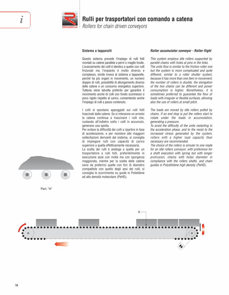
58
Rulli per trasportatori con comando a catenaRollers for chain driven conveyors
Sistema a tapparulli
Questo sistema prevede l’impiego di rulli follimontati su catene parallele a perni o maglie forate.L’avanzamento dei colli è identico a quello con rullifrizionati ma l’impianto è molto diverso ecomplesso, simile invece al sistema a tapparelle,perché ha più organi in movimento, un numerodoppio di rulli, possibilità di allungamento diversodelle catene e un consumo energetico superiore.Tuttavia viene talvolta preferito per garantire ilmovimento anche di colli con fondo sconnesso opoco rigido rispetto al carico, con sentendo anchel’impiego di rulli a passo con tenuto.
I colli si spostano appoggiati sui rulli follitrascinati dalle catene. Se si interpone un arrestola catena continua a trascinare i rulli che,ruotando all’indietro sotto i colli in accumulo,generano una spinta.Per evitare la difficoltà dei colli a ripartire in fasedi accelerazione, e per resistere alle maggiorisollecitazioni derivanti dal sistema, si consigliadi impiegare rulli con capacità di caricosuperiore a quella effettivamente necessaria.La scelta dei rulli è analoga a quella per untrasportatore a rulli folli, preferibilmente inesecuzione asse con molla ma con sporgenzamaggiorata, mentre per la scelta delle catenesono da preferirsi quelle con fori di diametrocompatibile con quello degli assi dei rulli; siconsiglia lo scorrimento su guide in Polietilenead alta densità molecolare (PeHD).
Roller accumulator conveyor - Roller flight
This system employs idle rollers supported byparallel chains with holes at pins in the links.The units flow is similar to the friction roller onebut the system is more complicated and quitedifferent, similar to a roller shutter system,because it has more than one item in movement,the number of rollers is double, the elongationof the two chains can be different and powerconsumption is higher. Nonetheless, it is sometimes preferred to guarantee the flow ofloads with irregular or flexible surfaces, allowingalso the use of rollers at small pitch.
The loads are moved by idle rollers pulled bychains. If an end stop is put the rollers start torotate under the loads in accumulation,generating a pressure.To avoid the difficulty of the units restarting inthe acceleration phase, and to the resist to theincreased stress generated by the system,rollers with a higher load capacity thannecessary are recommended.The choice of the rollers is simular to one madefor an idle rollers conveyor, with preference fora shaft execution with spring but with longerprotrusion, chains with holes diameter incompliance with the rollers shafts, and chainguides in Polyethilene high density (PeHD).
Part. "A"
A
i

59
Indicazione di impiego e criteri di progettazioneApplication indications and design criteria
Il calcolo del tiro su ogni catena risulta sommandoalla forza «Tm», che imprime il movimento alcarico, la resistenza al rotolamento «Ta» con i colliin accumulo.
La potenza da installare equivale:
Dove η = rendimento motoriduttore
Si deve prestare particolare attenzione alrendimento del motoriduttore, perché si richiedeuna velocità angolare bassa e coppia motriceelevata, essendo i rinvii catena ottenuti conpignoni di diametro primitivo relativamenteelevato.È importante curare il parallelismo e l’ortogonalitàdei rulli, perché i colli, sfregando contro le guide dicontenimento, avrebbero difficoltà a ripartire; atale scopo possono servire dei tenditori a vite chemantengano le catene tese e aderenti alle loroguide di scorrimento.
The pull calculation of every chain resultsadding the rotation resistance «Ta» with theloads in accumulation, to the «Tm» force, whichgives the motion to the load.
The power to be installed is equal to:
Where η = gearmotor efficiency
Particular attention should be given to thegearmotor efficiency, because a low angularspeed and high motor torque are requested, asthe gear transmission is obtained from pinionswith a relatively big diameter.It is important to take particular attention to theparallelism and squareness of the rollers,because the loads, rubbing against thecontainment guides, could have difficulties inrestarting; for this purpose, screw tensioningsystem, that maintain the chains stretched andclose fitting to their guides, may be useful.
T =
Tm = 0,15 • (Pm + Pt • n1 + Pu • nc) [daN]
Ta = 0,05 • (Pu • nc) [daN]
[daN]N. cateneN. chains
Tm + Ta
N = [kW](Tm + Ta) • v
100 • η

60
Rulli per trasportatori comandati con cinghiaRollers for belt driven conveyors
TRASPORTATORE A RULLI COMANDATI CON CINGHIA:DEFINIZIONE E TERMINOLOGIA
Trasportatore a rulli comandati con cinghia:serie di rulli sostenuti da una struttura, atti allamovimentazione dei colli, che ricevono ilcomando da una cinghia.
Cinghia: elemento di trasmissione in materialeelastico, che permette l’avvolgimento su tamburie pulegge, con vari tipi di rinforzi alla carcassaatti a limitare l’allungamento ed aumentare laresistenza a trazione; può essere di sezionepiatta o tonda ed è giuntata ad anello chiuso,tesa tra due elementi cilindrici.
Rullo portante: rullo su cui appoggia il carico.
Comando: un assieme di elementi meccanici,elettrici e strutturali atti a portare in movimentola cinghia.
Tamburo di comando: elemento cilindrico, con osenza bombatura, girevole su un albero rotante,che trasmette il moto alla cinghia piatta che loavvolge; spesso è rivestito in gomma ed è postonormalmente in testa alla direzione del nastro.
Tamburo di rinvio: elemento cilindrico, con osenza bombatura, girevole su un asse fissooppure fisso su albero rotante, normalmentemontato alla estremità del trasportatore oppostarispetto al tamburo di comando.
Tamburo tenditore: tamburo oppure rullo aposizione regolabile per compensare variazionidi lunghezza della cinghia dovute ad usura,stiramenti, variazioni climatiche.
Rullo di pressione: rullo che mantiene la cinghiapiatta di comando a contatto con i rulli portanti.
Rullo di ritorno: rullo sul quale appoggia lacinghia nel percorso di ritorno.
Rullo di rincalzo: rullo o tamburo posto vicino altamburo di comando per aumentare l’angolo diavvolgimento e tenere in guida la cinghia.
Albero motore: nei trasportatori a cinghia tondatrasmette il moto direttamente, oppure attraversouna serie di pulegge su di esso montate, ai singolirulli collegati ognuno con un anello di cinghia.
Larghezza: (utile) distanza tra i lati interni dellespalle.
BELT DRIVEN ROLLER CONVEYOR: DEFINITION AND TERMINOLOGY
Belt driven roller conveyor: a series of rollerssupported by a structure, suitable for unithandling loads which are driven by a belt.
Belt: driving element made of elastic materialsuitable to allow enveloping on drums andpulleys, with various kinds of reinforcements tothe frame specifically designed for limiting thebelt elongation and increasing the tensilestrenght. It may have flat or round section and isspliced in closed loop tensioned by twocylindrical elements.
Carrying roller: roller supporting the load.
Drive: an assembly of mechanical, electrical andstructural parts suitable to set the belt in motion.
Drive pulley: cylindrical element with or withoutswell, turning on a revolving shaft whichtransmits motion to the flat belt enveloping it. Itis often coated and, in most common plants, itis located at the head end of the belt direction.
Reversing pulley: cylindrical element with orwithout crowning, turning on a fixed shaft orfixed on a rotating shaft, usually mounted at theconveyor end opposite to the drive pulley.
Belt tensioning pulley: pulley or roller withadjustable position in order to compensate thebelt length variations due to wear, stretching,climatic changes.
Pressure roller: roller keeping the flat drivingbelt in contact with the carrying rollers.
Return roller: roller supporting the empty belt inthe return part.
Snub roller: roller or pulley placed near the drivepulley to increase the enveloping angle and tomaintain the belt alignment.
Driving shaft: on round-section belt conveyors,it transmits motion, directly or through a seriesof pulleys mounted on it, to all rollers singlyconnected by a belt loop.
Width: (working) distance between the internalsides of the side frames.
i

1 2 5 7 6 4 3
2 31
1 – tamburo di comando – drive pulley;2 – cinghia piatta – flat-section belt;3 – tamburo di rinvio-tenditore – tensioning-reversing pulley4 – rullo di rincalzo – snub roller;5 – rullo portante – carrying roller;6 – rullo premente – pressure roller;7 – rullo di ritorno – return roller.
61
Indicazione di impiego e criteri di progettazioneApplication indications and design criteria
APPLICAZIONI
I trasportatori a rulli comandati con cinghia sonoadatti al trasporto di una grande varietà di colli,di forma regolare o irregolare, pesanti e leggeri.Caratterizzano il sistema la marcia particolar -mente silenziosa, anche alle alte velocità, e lapossibilità di scorrimento tra cinghia e rullo incaso di sovraccarico, condizione favorevole peril trasporto di merce delicata o per ottenere unaccumulo con spinta tra i colli, benché nonsempre consigliabile.Il percorso del trasporto è generalmente piano, maè ammessa una leggera pendenza purchè sianorispettati i limiti per l’aderenza tra rullo e collo.I sistemi principali di trasmissione sono due:- a cinghia piatta, in cui un’unica cinghia tesa
tra tamburo di comando e tamburo di rinviocorre sotto i rulli portanti, trasmettendo loro ilmoto (A).
- a cinghia tonda, dove ciascun rullo è collegatosingolarmente mediante una cinghia ad ununico albero motore posto longitudinalmentesotto il piano dei rulli portanti (B).
APPLICATIONS
The belt driven roller conveyors are suitable forhandling a great variety of heavy and light loads ofregular or irregular shape.The system features a particularly silent running,also at high speeds, and the possibility of slidingaction between the belt and the roller in case ofoverload, this being a favourable condition for thetransfer of fragile goods or for the accumulationtransport with pressure between loads units,although this is not always recommended.The conveyor is usually flat, but a slight slope isadmitted, provided the required adhesion limitsbetween roller and load are observed.The main transmission systems are two:- with flat-section belt, where a unique belt
tensioned between the drive and the reversingpulley runs under the carrying rollers andtrasmits them the motion (A).
- with round-section belt, where each roller issingly connected through a belt to a uniquedriving shaft located lengthwise under thecarrying rollers plane (B).
A
B
A
1 – albero motore – driving shaft;2 – cinghia tonda – round-section belt; 3 – rullo portante – carrying roller.
B

62
Rulli per trasportatori comandati con cinghiaRollers for belt driven conveyors
Confluenza con curva a rulli folliConverging with idle roller curve
Confluenza obliquaSpur converging
Deviazione ortogonaleOrthogonal deviation
Deviazione ortogonaleOrthogonal deviation
SCHEMI ED ESEMPI DI APPLICAZIONE APPLICATION EXAMPLES AND DIAGRAMS
i

63
Indicazione di impiego e criteri di progettazioneApplication indications and design criteria
SIMBOLI
A = lunghezza asse del rullo [mm]B = lunghezza mantello del rullo [mm]C = lunghezza di battuta o di montaggio di un rullo [mm]D = diametro rullo [mm]e = efficienza globale di trasmissioneEL = larghezza di montaggio del trasportatore [mm]Fr = fattore d’attritoH = dislivello di un trasportatore in pendenza [m]I = interasse dei rulli portanti [mm]Lt = lunghezza del trasportatore [m]n = numero dei rulli interessati da un colloN = potenza del motoriduttore [kW]n1 = numero dei rulli portanti comandati da un unico comandonc = numero dei colli sul tratto motorizzato da un unico comando nr = numero dei rulli di ritornons = numero dei rulli prementiP = carico massimo effettivo gravante su un rullo [daN]P1 = carico nominale gravante su un rullo [daN]Pb = peso di un metro (1 m) di lunghezza della cinghia [daN/m]Pc = capacità di carico di un rullo (portata) [daN]Pr = peso delle parti rotanti di un rullo portante [daN]Ps = peso delle parti rotanti di un rullo premente [daN]Pu = peso di un collo [daN]Ri = raggio interno della curva sulla spalla interna [mm]Te = tiro utile della cinghia [daN]T1 = tensione massima della cinghia su tamburo comando [daN]T2 = tensione minima della cinghia sul tamburo di comando [daN]v = velocità di trasporto [m/s]X = larghezza del collo [mm]Y = lunghezza del collo [mm]η = rendimento del motoriduttore
SYMBOLS
A = roller shaft length [mm]B = roller shell length [mm]C = roller fixing ends length [mm]D = roller diameter [mm]e = total transmission efficiencyEL = conveyor in between width of a conveyor system [mm]Fr = friction factorH = height difference of an inclined conveyor [m]I = carrying roller pitch [mm]Lt = conveyor length [m]n = number of rollers under a load unitN = gear motor power [kW]n1 = number of the carrying rollers driven by one drivenc = number of the load units on a section driven by one drivenr = number of the return rollersns = number of the pressure rollersP = maximum actual load on a roller [daN]P1 = nominal load on a roller [daN]Pb = weight of one linear meter (1 m) of belt [daN/m]Pc = roller load capacity [daN]Pr = weight of the carrying roller rotating parts [daN]Ps = weight of the pressure roller rotating parts [daN]Pu = load unit weight [daN]Ri = inner radius of the curve [mm]T1 = maximum belt tension on the drive pulley [daN]T2 = minimum belt tension on the drive pulley [daN]Te = useful belt pull [daN]v = handling speed [m/s]X = load width [mm]Y = load length [mm]η = gear motor efficiency

64
Rulli per trasportatori comandati con cinghiaRollers for belt driven conveyors
RICHIAMI DALLE PAGINE PRECEDENTI
Prima di affrontare il calcolo della trasmissionenei trasportatori con comando a cinghia, ènecessario considerare i criteri di progettazionegià trattati da pag. 18 a pag. 31, perché sonofondamentali per la costruzione di qualsiasi tipodi trasportatore a rulli.Per maggior comodità, riportiamo di seguito leformule già trattate.
Per la scelta dei rulli per i sistemi a cinghiapiatta, sono necessarie ulteriori valutazioni,come indicato a pag. 66.
Calcolo della struttura:
L = luce-distanza tra gli appoggi [mm]Q = carico totale sulla sezione, compreso
il peso dei rulli e delle spalle [N]W = modulo di resistenza flessionale [mm3]J = momento di inerzia della sezione rispetto
all’asse neutro [mm4]E = modulo di elasticità [MPa]
RECALLS FROM THE PREVIOUS PAGES
Before going on into the chain belt drivenconveyor transmission calculations, it isnecessary to consider the design criteriamentioned from page 18 to page 31, as they arefundamental to the construction of any rollerconveyor system.For facility purposes, the formulas are againlisted below:
For the selection of the rollers for flat beltconveyor systems, further considerations arerequired, as mentioned on page 66.
Structure calculation:
L = span-distance between the supporting points [mm]
Q = total load on the section, roller and frame weights included [N]
W = deflection resistance module [mm3]J = section moment of inertia respect
to the neutral axis [mm4]E = elasticity module [MPa]
f =
σ amm. ≥ σ =
σ amm. = 140 MPa per S235JR (St 37)
≤E • J
Q • L3
8 • W
Q • L
384
5
360
L•
I = n ≥ 3N
Y dovewhere
P =2n
3 • PuP =
n
2 • PuP1 =
n
Puoppureor
Pc ≥ P
EL = C con asse forato e filettato / drilled and thread shaft
C = X + 50 minimo / minimum
EL = C + 1 con estremità dell’asse libere / with free shaft ends
EL = (Ri + X)2 + (Y/2)2 - Ri + 50 minimo / minimum
i

1
2
3
1
2
3
EL
EL
65
Indicazione di impiego e criteri di progettazioneApplication indications and design criteria
TRASMISSIONE CON CINGHIA PIATTA
La cinghia corre sotto la corsia di rulli portantied è premuta contro di essi allo scopo di tras -met tere il moto.La pressione è esercitata dai rulli prementi che,montati in numero di uno ogni due oppure trerulli portanti e regolati opportunamente inaltezza, garantiscono l’aderenza tra cinghia erulli portanti.In caso di funzionamento con accumulo dei colliè richiesta una regolazione fine dell’altezza deirulli prementi.Nel percorso di ritorno la cinghia è sostenuta dairulli di ritorno che sono opportunamentedistanziati, normalmente in modo da appog -giarsi ai sostegni del trasportatore, e possibil -mente regolabili sull’orizzontale in modo dagarantire la centratura della cinghia.I rulli prementi e i rulli di ritorno, come pure itamburi, possono essere più corti dei rulliportanti (fig. 1) in rapporto alla larghezza dellacinghia, ma sovente per semplicità costruttiva simantiene la stessa misura (fig. 2).Questo sistema prevede l’impiego di undispositivo tenditore che nei casi più semplici èposto in estremità come in fig. A a pag. 61.La corsa minima da assegnare al tenditore è parialmeno all’1% della lunghezza del trasportatore.È anche consigliabile un dispositivo che garan -tisca la perpendicolarità dell’asse di rotazione deltamburo (o rullo) tenditore rispetto alla direzionedella cinghia.Il movimento arriva al tamburo di comando daun motoriduttore che comunemente è esterno ecollegato con catena, ma può essere ad alberocavo calettato direttamente sull’albero deltamburo, oppure addirittura interno al tamburostesso che in tal caso prende il nome dimototamburo. È evidente la maggior semplicitàimpiantistica dell’ultimo sistema. Quando sianecessaria una variazione di velocità si interponeun variatore meccanico oppure si fa uso dimotore a velocità variabile.Determinante per la scelta della tensione inizialedella cinghia, che condiziona la robustezza eperciò il costo della cinghia stessa e deglielementi meccanici, è la capacità di adesione tracinghia e tamburo di comando. Questa puòessere aumentata con un rivestimento deltamburo di comando in gomma liscia oppurelavorata (a lisca di pesce oppure romboidale). Sipuò inoltre aumentare l’angolo di avvolgimentofacendo uso di tamburi (o rulli) di rincalzo.
FLAT-SECTION BELT TRANSMISSION
The belt runs under the path of the carryingrollers and is pressed against these to enable themotion transmission.Pressure is exerted by the pressure rollerswhich, being mounted in number of one everytwo or three carrying rollers and being suitablyadjusted in height, ensure adhesion between thebelt and the carrying rollers.In case of operation with unit loads accumulation,a fine adjustment of the pressure rollers heightis required.Along its return part the belt is supported by thereturn rollers which are suitably spaced,normally so as to rest on the conveyor supports,and, if possible, are horizontally adjustable so asto ensure the belt centering.The pressure rollers and return rollers as well asthe pulleys may be shorter than the carryingrollers (fig. 1) in relation to the belt width, butoften, for construction simplicity purposes, thesame size is maintained (fig. 2).This system features the use of a tensioningdevice which, in the simplest cases, is located atthe end, as shown in fig. A at page: 61. Theminimum stroke of the belt tensioner should beat least equal to 1% of the conveyor length.Recommended is also the use of a deviceensuring the perpendicularity of the tensioningpulley (or roller) rotation axis with respect to thebelt direction.The drive pulley receives motion from a gearedmotor which is usually mounted externally andconnected by chain, but may also have a hollowshaft directly splined to the drum shaft, or evenplaced inside the drum which, in this case, iscalled drummotor. It is evident that the lattersystem features a greater simplicity of plantengineering. When a speed variation is required,it is possible to mount a mechanical speedvariator or a variable speed motor.Decisive for the selection of the initial belttension, which conditions the sturdiness andtherefore the cost of the belt and of themechanical parts, it is the fiction factor betweenthe belt and the drive pulley. This can beincreased by means of a drive pulley flat rubbercoating or fish-bone or diamond shaped.Besides, it is possible to increase the envelopingangle by use of snub pulleys (or rollers).
1 – rulli portanti;2 – rulli prementi; 3 – rulli di ritorno
1 – carrying rollers; 2 – pressure rollers; 3 – return rollers
fig. 1
fig. 2

66
Rulli per trasportatori comandati con cinghiaRollers for belt driven conveyors
Scelta dei rulli
Rulli prementi – Si ipotizza un carico pari al 10%della tensione massima della cinghia «T1».
Rulli portanti – Sono caricati dal peso dei collitrasportati e dalla pressione della cinghia, cheagisce dal basso in alto. Il peso dei colli determinaun carico «P» da valutare come indicato a pag. 64mentre la cinghia esercita una pressione di caricoP = 0,1 • T1, pari al carico dei rulli prementi.Normalmente il carico dal basso, prodotto dallacinghia, è nettamente inferiore a quello derivantedal peso dei colli e si preferisce trascurarlo. Ciònonostante conviene sempre una verifica, prestan -do attenzione che i rulli prementi non determininoun evidente angolo di deviazione della cinghia, eche la pretensione della stessa non sia eccessiva.Il rullo viene comunque scelto per il più elevato deidue carichi.
Rulli di ritorno – Normalmente si scelgono ugualiai rulli prementi tuttavia un corretto dimen -sionamento valuta il carico che loro competecome segue:
Calcolo della trasmissione
Tiro utile cinghia
+ trasportatore in salita – trasportatore in discesadove
Fattore d’attritoFr = 0,06
Selection of rollers
Pressure rollers – A load equal to 10% of themaximum belt tension «T1» is supposed.
Carrying rollers – They support the weight ofthe handled goods and the belt pressure exertedupwards. The weight of the goods determines aload to be calculated as shown on page 64,while the belt exerts a load pressure P = 0,1 • T1equal to the load of the pressure rollers.Normally, the upwards directed load, producedby the belt, is definitely smaller than the loadresulting from the goods weight, and therefore itis preferable to disregard it. Nevertheless, it isalways convenient to make a check taking carethat the pressure rollers should not determinean apparent belt deviation angle, and the beltpretension should not be excessive.In any case, the roller must be selected for thehigher of the two loads.
Return rollers – These are usually selectedequal to the pressure rollers, neverthelessthrough a correct sizing it is possibile toevaluate their corresponding load as follows:
Transmission calculation
Useful belt pull
+ conveyor upwards – conveyor downardswhere
Friction factorFr = 0,06
P = 0,1 • T1 [daN] Pc ≥ P [daN]
Pc ≥ P [daN][daN]P =nr
Pb • Lt
± Td [daN]Te =e
Fr • Gp
Td = Pu • nc •
Lt
H
Gp = (Pu • nc) + (Pr • n1) + (Pb • Lt) + (Ps • ns)
i
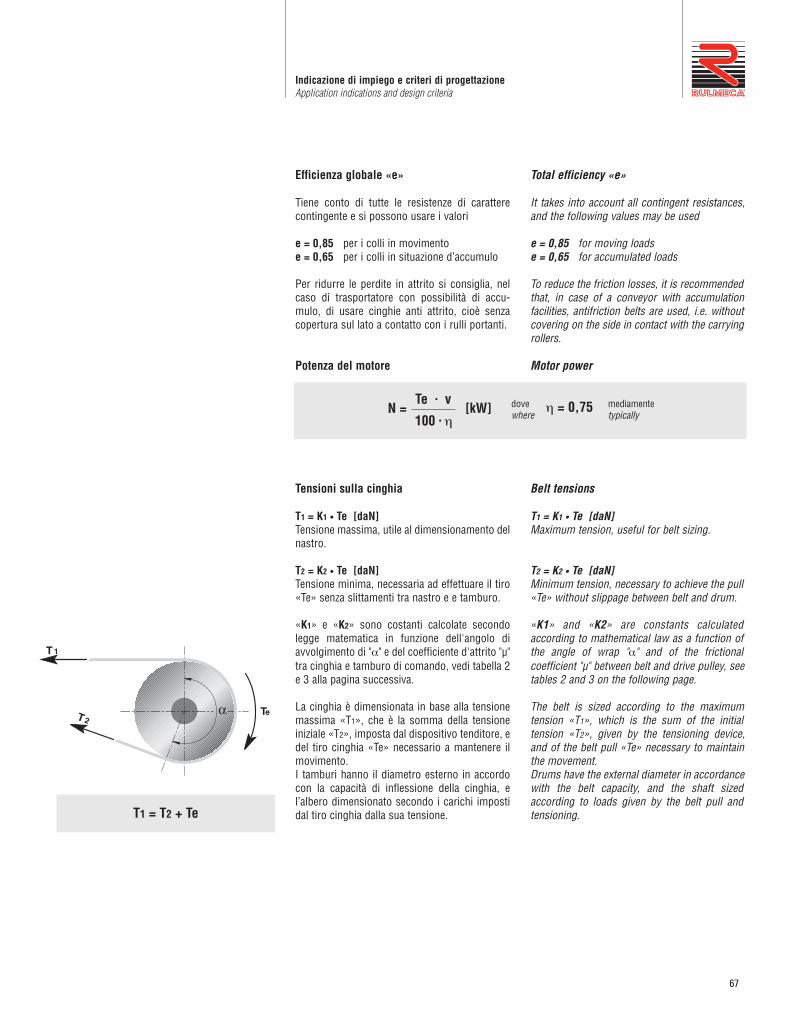
67
Indicazione di impiego e criteri di progettazioneApplication indications and design criteria
Efficienza globale «e»
Tiene conto di tutte le resistenze di caratterecontingente e si possono usare i valori
e = 0,85 per i colli in movimentoe = 0,65 per i colli in situazione d’accumulo
Per ridurre le perdite in attrito si consiglia, nelcaso di trasportatore con possibilità di accu -mulo, di usare cinghie anti attrito, cioè senzacopertura sul lato a contatto con i rulli portanti.
Potenza del motore
Tensioni sulla cinghia
T1 = K1 • Te [daN]Tensione massima, utile al dimensionamento delnastro.
T2 = K2 • Te [daN]Tensione minima, necessaria ad effettuare il tiro«Te» senza slittamenti tra nastro e e tamburo.
«K1» e «K2» sono costanti calcolate secondolegge matematica in funzione dell'angolo diavvolgimento di "α" e del coefficiente d'attrito "µ"tra cinghia e tamburo di comando, vedi tabella 2e 3 alla pagina successiva.
La cinghia è dimensionata in base alla tensionemassima «T1», che è la somma della tensioneiniziale «T2», imposta dal dispositivo tenditore, edel tiro cinghia «Te» necessario a mantenere ilmovimento.I tamburi hanno il diametro esterno in accordocon la capacità di inflessione della cinghia, el’albero dimensionato secondo i carichi impostidal tiro cinghia dalla sua tensione.
Total efficiency «e»
It takes into account all contingent resistances,and the following values may be used
e = 0,85 for moving loadse = 0,65 for accumulated loads
To reduce the friction losses, it is recommendedthat, in case of a conveyor with accumulationfacilities, antifriction belts are used, i.e. withoutcovering on the side in contact with the carryingrollers.
Motor power
Belt tensions
T1 = K1 • Te [daN]Maximum tension, useful for belt sizing.
T2 = K2 • Te [daN]Minimum tension, necessary to achieve the pull«Te» without slippage between belt and drum.
«K1» and «K2» are constants calculatedaccording to mathematical law as a function ofthe angle of wrap "α" and of the frictionalcoefficient "µ" between belt and drive pulley, seetables 2 and 3 on the following page.
The belt is sized according to the maximumtension «T1», which is the sum of the initialtension «T2», given by the tensioning device,and of the belt pull «Te» necessary to maintainthe movement.Drums have the external diameter in accordancewith the belt capacity, and the shaft sizedaccording to loads given by the belt pull andtensioning.
[kW]N =100 • η
Te • vη = 0,75dove
wheremediamentetypically
T1 = T2 + Te
T 1
T 2α Te

68
Rulli per trasportatori comandati con cinghiaRollers for belt driven conveyors
Riportiamo nella tabella seguente alcuni valori di“K1” e “K2” al variare di “α” e “µ”.
Proponiamo indicativamente alcuni valori di “µ” daattribuire alle condizioni di impiego del tamburopiù frequenti.
The table below gives some values of “K1” and“K2” with varying “α” and “µ”.
For your guidance, we are giving, below, somevalues of “µ” to be assigned to the most commonoperating conditions of the pulley.
0,1 tamburo umido bagnato moist wet pulley
0,15 tamburo gommato in condizione scivolosa rubber-coated pulley in slippery condition
0,2 tamburo nudo umido moist bare pulley
0,3 tamburo nudo secco dry bare pulley
0,4 tamburo gommato secco dry rubber-coated pulley
condizioni di impiegoµ operating conditions
Tabella 3 / Table 3
α K1 K2 K1 K2 K1 K2 K1 K2 K1 K2 K1 K2 K1 K2 K1 K2
180° 3,70 2,70 2,66 1,66 2,14 1,14 1,84 0,84 1,64 0,64 1,50 0,50 1,40 0,40 1,26 0,26
190° 3,54 2,54 2,55 1,55 2,06 1,06 1,77 0,77 1,59 0,59 1,46 0,46 1,36 0,36 1,24 0,24
200° 3,39 2,39 2,45 1,45 1,99 0,99 1,72 0,72 1,54 0,54 1,42 0,42 1,33 0,33 1,21 0,21
210° 3,26 2,26 2,36 1,36 1,92 0,92 1,67 0,67 1,50 0,50 1,38 0,38 1,30 0,30 1,19 0,19
215° 3,20 2,20 2,32 1,32 1,89 0,89 1,64 0,64 1,48 0,48 1,37 0,37 1,29 0,29 1,18 0,18
220° 3,14 2,14 2,28 1,28 1,87 0,87 1,62 0,62 1,46 0,46 1,35 0,35 1,27 0,27 1,17 0,17
230° 3,02 2,02 2,21 1,21 1,81 0,81 1,58 0,58 1,43 0,43 1,33 0,33 1,25 0,25 1,16 0,16
240° 2,92 1,92 2,14 1,14 1,76 0,76 1,54 0,54 1,40 0,40 1,30 0,30 1,23 0,23 1,14 0,14
0,1 0,15 0,2 0,25 0,3 0,35 0,4 0,5µTabella 2 / Table 2
i

69
Indicazione di impiego e criteri di progettazioneApplication indications and design criteria
Sistemi particolari
Un sistema adatto ad aumentare la sicurezzadegli addetti prevede che i rulli portanti non sianotrattenuti in alto, cioè che gli assi siano alloggiatientro un’asola aperta (come da figura). In questomodo in caso di incidente si ha il vantaggio dellafuoriuscita dei rulli portanti, liberando il corpoestraneo eventualmente introdotto tra nastro erullo. Va comunque notato che con questo siste -ma la pressione tra rullo e cinghia è propor -zionale al peso dei colli trasportatori.
Sistemi ad accumulo che limitano la spinta tra icolli si ottengono in vari modi:- montaggio dei rulli prementi su supporti a molla.- impiegando dei rulli prementi arretrabili a
comando.- con il sistema a piani inclinati, dove i rulli
portanti si allontanano dalla cinghia al cresceredella spinta.
Alcuni di questi sistemi sono protetti dal brevetto.
Special systems
A system suitable to increase safety for operatorsfeatures carrying rollers not held in the upperportion, i.e. having their shafts housed in anopen slot as per the drawing. This has theadvantage that, in case of accident, it is possibleto pull off the carrying rollers and to remove anyforeign matter eventually lodged between beltand roller.However, it should be noted that, with this system,the pressure between the roller and the belt isproportional to the weight of the handled loads.
Load accumulating systems capable of limitingthe pressure between loads are obtained invarious ways:- by mounting pressure rollers on spring brackets- by use of pressure rollers that can be moved
backwards by a proper control.- with an inclined planes system where the
carrying rollers drive away from the belt aspressure increases.
Some of these systems are covered by patent.

70
Rulli per trasportatori comandati con cinghiaRollers for belt driven conveyors
Pulegge
Le pulegge per accumuli sono presentate a pagina 207The wheels for accumulation are shown at page 207
TRASMISSIONE CON CINGHIA TONDA
Il trasportatore trae il moto da un lungo albero,chiamato albero motore, posto longitudi nalmen -te sotto la corsia a rulli e collegato con un moto -riduttore. Un anello di cinghia a sezione tondacollega singolarmente ogni rullo all’albero,scorrendo in una gola ricavata nel mantello delrullo oppure nella puleggia di estremità del rullo(vedi anche fig. B pag. 61). Normalmente laprofondità della gola è sufficiente a non faraffiorare la cinghia sul piano rulli, e in tal modoil rullo è disponibile in tutta la sua lunghezza peril trasporto del materiale.Il sistema è molto sicuro per l’operatore eparticolarmente esente da incidenti da sovrac -carico in quanto ogni rullo singolarmente puòessere fermato con una mano.
Si realizza un accumulo con spinta tra i collitrasportati predisponendo lo slittamento traalbero motore e rulli portanti.Ciò è ottenibile collegando le cinghie a puleggeche possono slittare sul l’albero motore.
ROUND BELT TRANSMISSION
The conveyor system is driven by a long shaftcalled driving shaft, mounted lengthwise underthe rollers path and connected to a gear motor.A round-section belt ring connects each singleroller to this shaft and run in a groove providedin the roller tube or in the roller end wheel, seealso fig. B pag. 61. Usually, the groove depth issuch that the belt cannot pull out of position andsettle on the roller surface, so that the roller isavailable in all its length for the materialhandling.This system is very safe for the operator andparticularly free from accidents due to overload,since every roller can be stopped singularly withone hand.
An accumulation with pressure between theconveyed loads is achieved by allowing aslippage between the driving shaft and thecarrying rollers. This can be obtained either byletting the belts slip or by connecting them topulleys that can slide on the driving shaft.
* da determinare consultando i fornitori delle cinghie in rapporto alle caratteristiche delle stesse ed ai diametri di avvolgimento.
* to be determined applying to the beltssuppliers in relation to the beltcharacteristics and diameters.
i
71
Indicazione di impiego e criteri di progettazioneApplication indications and design criteria
È possibile ottenere un effetto frenante in -vertendo il collegamento di un rullo ad intervalliregolari in modo che questo ruoti in direzioneopposta agli altri (fig. 1).Si può ridurre la forza di trascinamento colle -gando in serie alcuni rulli ad un primo rullo chericeve il moto dall’albero motore (fig. 2).La cinghia è in materiale resistente all’usura e moltoelastico (normalmente Poliuretano); sarà cura delcostruttore di cinghie prescrivere la tensioneiniziale, e indicare l’allungamento minimo richiestoe la caratteristica elastica, in modo che si possanoricavare i carichi che ne derivano sull’albero motore.Questa trasmissione è particolarmente silenziosa,sia perché le cinghie non producono rumore, siaperché, essendo tese, impediscono all’estremitàdell’albero dei rulli di vibrare entro gli appoggi.Il collegamento molto elastico permette manovreimpensabili in altri sistemi, quale quella diorientare i rulli di un deviatore senza fermarli (fig. 3).L’albero motore sarà supportato a distanze tali dacontenere la freccia (ad esempio entro 1 mm).La distanza minima tra l’asse di rotazione dell’alberomotore e l’asse di rotazione dei rulli deve esserealmeno 3 volte il diametro del rullo.Il diametro dell’albero motore o dell’eventualepuleggia è di solito inferiore al diametro di fondo goladel rullo.
Calcolo della trasmissione
Potenza del motore
+ trasportatore in salita- trasportatore in discesa
dove
Fr = 0,05 per colli in movimentoFr = 0,08 per colli in situazione di accumuloη = 0,75 mediamente
La scelta della dimensione della cinghia è infunzione della potenza da trasmettere al singolorullo e della velocità di trasporto.
I rulli si scelgono come indicato a pag. 66,ignorando il carico dato dalla tensione dellacinghia, che di solito è trascurabile rispetto alcarico da trasportare.
It is possible to obtain a breaking effect by invertingthe connection of one roller at regular intervals sothat it rotates in an opposite direction (fig.1)The dragging force can be reduced by connectingsome rollers in series to a first roller receiving themotion from the driving shaft (fig. 2).The belt is made of wear resistant and veryelastic material (normally Polyurethane); it is upto the belt manufacturer to prescribe elongationand the elastic characteristic, so that one maywork out the loads resulting on the driving shaft.This transmission is particularly silent, becausethe belts produce no noise and because these,being stretched, prevent the rollers shaft endfrom vibrating in between the bearings.The very elastic connection allows operationsunthinkable on other systems, such as theorientation of the rollers of a deviator withoutstopping them (fig. 3).The driving shaft shall be supported at suchdistances as to restrain the deflection (forinstance within 1 mm).The minimum distance between the drivingshaft rotation axis and the roller rotation axismust be at least 3 times the roller diameter.The diameter of the driving shaft or of the pulley,if any, is usually smaller than the roller groovebottom diameter.
Trasmission calculation
Motor power
+ conveyor upwards- conveyor downwards
where
Fr = 0,05 for moving load unitsFr = 0,08 for accumulated load unitsη = 0,75 averagely
The selection of the belt size depends on thepower transmitted to the single roller and on thehandling speed.
Rollers are selected as shown on page 66,neglecting the load given by the belt tensionwhich is usually negligible with respect to theload to be handled.
[kW]N =100 • η
(Fr • Gt ± Td) • v
Gt = (Pu • nc) + (Pr • n1) Td = Pu • nc •
Lt
H

72
Rulli per trasportatori comandati con cinghiaRollers for belt driven conveyors
Fig. 1 esempio di trasmissione per ottenere un effetto frenante in accumulotransmission example to obtain a braking effect while accumulating
Fig. 2 esempio di trasmissione per ridurre la forza di trascinamento in accumulotransmission example to reduce the dragging force while accumulating
Fig. 3 esempio di deviazione con orientamento dei rullideviation example with roller orientation
Fig. 4 esempio di deviazione ortogonale con sistema combinatoorthogonal deviation example with combined system
i

Rulli per trasportatoria gravità
Rollers for gravity conveyors
73
1
Serie GLGL series
Serie 111111 series
Nuovo tipo per applicazioni silenzioseNew type for noiseless applications
Serie GMGM series
Serie RTLRTL series
Serie MP-MPRMP-MPR series
Serie MPSMPS series
Serie PSPS series
Rulli guidaGuide rollers
Esecuzioni tubo a richiestaTube executions on request
74
78
89
Serie 117117 series
82
91
94
98
102
110
116
118
Serie 119119 series
106

74
SerieSeries GL1
RULLI FOLLIPER TRASPORTO DI COLLICON CARICHI LEGGERI E MEDI IN AMBIENTI INTERNI NORMALI
Sono rulli in acciaio con rotolamento su cuscinettiradiali a sfere schermati e prelubrificati che li ren -dono particolarmente scorrevoli, con la più elevatacapacità di carico della loro categoria.I tipi GL/8–10–12 prevedono testate con cuscinettia pieno riempimento di sfere, mentre la particolareconfigurazione dei rulli GL/56-58-60 ha determi -nato l’impiego di cuscinetti con gabbia. Il tubo, bombato alle estremità, è zincato nell’ese -cu zione standard “Z” nella maggior parte dei tipiper un miglior grado di finitura e i più svariati im -pie ghi, ad esclusione del diametro 76 che prevedeun’esecuzione a richiesta con zincatura elettro -litica “J”.L’asse a molla rende veloci e agevoli le operazionidi montaggio nei trasportatori.Per l’impiego nelle curve a rulli folli si veda pag 197.La particolare forma delle testate, il grado di finituradei cuscinetti e l’accuratezza degli accoppiamenticonsentono un buon comportamento di questi rullianche nelle applicazioni comandate e per sostegnonastro, considerando attentamente i carichi am -messi in rapporto alla velocità (si veda tabella a pag77) L’impiego è normalmente consentito con tem -perature ambiente da –20° C a +100° C.
Consigliamo di attenersi all’esecuzione standard;per esecuzioni a richiesta si prega di indicare nelseguente ordine: il tipo, il diametro e l’esecuzioneasse, il diametro e l’esecuzione tubo, la lunghez -za “C”.
Esempi di codice di ordinazioneGL/8 8D 50Z 500GL/12 12R 50Z 600GL/13 12D 60JP 900
Tutte le quote sono espresse in mm.
IDLE ROLLERSFOR LIGHT AND MEDIUM UNITHANDLING CONVEYORS IN NORMALINTERNAL ENVIRONMENTS
The GL steel rollers with shield and prelubricatedradial ball bearings are particularly smoothrunning and have the highest load capacity intheir category. The GL/8-10-12 types have bearings without cagewhereas the special configuration of GL/56-58-60types have caused the use of bearings with cage.The swaged tube is zinc-plated in the standardexecution “Z” for most of the types for a higherfinishing grade and various applications, exceptfor 76 mm diameter having an electrolytic zinc-plating “J” on request. The spring loaded shaft offers a fast and easyinstallation into the conveyor system.For curves with idle rollers please refer to page 197.The particular shapes of the end-caps andassembly precision allow these rollers to behavecorrectly even in driven and belt applications, ifthe loads in relation to the system speed arecarefully considered (please see table at page 77).Normal applications temperature ranges from –20° C to +100° C.
We suggest conforming to the standardexecutions; for different executions pleasespecify: the type, the shaft diameter and execution,the tube diameter and execution, the “C” length.
Ordering code examplesGL/8 8D 50Z 500GL/12 12R 50Z 600GL/13 12D 60JP 900
All dimensions are in mm.

75
Rulli per trasportatori a gravitàRollers for gravity conveyors
Legenda delle sigle di esecuzioneD = asse con mollaS = asse fisso liscioF = asse con chiave fresataM = asse con estremità filettateR = asse forato e filettato
Z = tubo con zincatura a caldo (sendzimir)N = tubo in acciaio normaleJ = tubo con zincatura elettroliticaP = tubo con guaina morbida in PVC
Execution codes captionD = shaft with springS = fixed shaftF = shaft with slots obtained by millingM = shaft with threaded endsR = drilled and threaded shaft
Z = hot dip zinc tube (sendzimir)N = normal steel tubeJ = zinc-plated tubeP = soft PVC lagging tube
GL/56
GL/58
GL/8
GL/60
GL/10
GL/62
GL/12
GL/11
GL/13
D
D
D
D
D
D
D
D
D
Z
Z
Z
Z
Z
N
Z
Z
N
Z
N
Z
18
24
30
40
50
32
50
60
76
32
50
60
76
50
60
76
60
80
50
50
50
70
50
70
70
70
600
1000
1200
1400
1400
1600
1600
1400
1600
1600
1800
1600
1600
1800
1800
1
1,2
1,2
1,2
1,5
1,5
1,5
1,5
2
1,5
1,5
1,5
2
1,5
1,5
2
2
2
5
4
4
4
4
4
4
4
4
4
4
4
4
4
4
4
6
8
8
8
8
10
10
10
10
12
12
12
12
11
11
11
12
0,006
0,011
0,012
0,015
0,022
0,017
0,024
0,028
0,043
0,020
0,027
0,030
0,045
0,026
0,029
0,044
0,037
0,148
0,250
0,291
0,372
0,512
0,436
0,690
0,784
1,130
0,499
0,748
0,846
1,188
0,738
0,832
1,178
0,986
0,104
0,165
0,205
0,286
0,426
0,301
0,554
0,648
0,995
0,301
0,549
0,647
0,989
0,555
0,649
0,995
0,787
0,004
0,007
0,008
0,012
0,018
0,011
0,018
0,022
0,037
0,011
0,018
0,022
0,037
0,018
0,022
0,037
0,029
Tipo / Typed(ø) esec. D(ø) esec. min max
Tubo / Tube Esec. AsseShaft exec.
Esec. TuboTube exec.
Lungh. / Length C s e g C=200daN
al cmdaN
Peso / Weight Peso parti rotanti / Rotating parts weightCodice di ordinazione / Ordering codes Opzioni / Options
ch
Asse / Shaft C=200daN
al cmdaN
Per lunghezze "C" min. di montaggio in esecuzioni asse con molla si veda pag 28.
For minimum "C" length with spring loaded shaft pls see page 28.
6
8
8
10
10
12
12
ch11
12
S-M
S-M
S-M
S-F-M-R
S
S-F-M-R
N
N-J-P
N-J-P
N-J-P
J-P
N-J-P
J-P
N-J-P
J-P
N-J-P
GL/8 - 10 - 11 - 12 - 13
S-F-M-R
Tipi a richiesta / Types on request

76
SerieSeries GL1
5
2
6
6
2
6
8
4
8
10
4
10
11
4
11
12
4
12
d
e
g
10
6x12
5
12
8x15
5
d
M
f
d
ch
e
g
10
8
5
6
12
10
5
6
d
M
e
g*
v*
6
6
2
16,5
4,5
8
8
4
20,5
5,5
10
10
4
21,5
6,5
12
12
4
27,5
7,5
Esec. S Esec. F Esec. R Esec. M
GL/58
GL/56
GL/60-62
GL/8
GL/60
GL/10
GL/12
8
10
10
12
D
D
D
D
30
40
50
32
50
60
60
Z
Z
Z
Z
200
250
250
300
500
400
258
300
400
400
600
500
400
500
450
600
500
500
800
600
1000
800
Tipo / Typed(ø) esec. D(ø) esec.
Tubo / Tube
Rulli a stock / Stock rollers
Asse / Shaft Lungh. / Length" C"
* valori previsti per dadi bassi UNI 5589.* values foreseen for half nuts UNI 5589.
Esecuzioni assi a richiesta / Shaft execution on request

Tipo / Typed(ø) esec. D(ø)
Tubo / TubeAsse / Shaft
77
Rulli per trasportatori a gravitàRollers for gravity conveyors
ESECUZIONI ASSI A RICHIESTA / SHAFT EXECUTION ON REQUEST
GL/56
GL/58
GL/8
GL/60
GL/10
GL/11
GL/62
GL/12
GL/13
30
40
40
40
50
120
120
120
120
140
140
140
120
140
140
140
140
30
40
40
40
50
113
120
120
120
140
140
140
113
140
140
140
140
30
40
40
40
50
105
120
120
120
140
140
140
105
140
140
140
140
25
33
40
40
50
93
120
120
120
140
140
140
93
140
140
140
140
22
30
40
40
50
88
120
120
120
140
140
140
88
140
140
140
140
19
26
37
40
50
82
120
120
120
140
140
140
82
140
140
140
140
16
22
30
40
50
65
107
118
120
125
140
140
65
125
140
140
140
19
26
40
46
54
92
101
105
107
134
140
54
107
134
140
140
13
22
37
40
42
81
88
92
94
118
140
42
94
118
140
140
9
20
33
35
33
71
78
81
83
104
140
33
83
104
140
136
6
17
30
32
26
65
70
73
74
94
140
26
74
94
140
122
12
27
29
22
58
64
66
68
85
138
22
68
85
138
111
9
24
27
17
53
59
60
62
78
126
17
62
78
126
102
12
37
50
52
49
65
108
12
49
65
108
84
43
45
33
43
94
33
43
94
56
82
82
39
≤ 200 250 300 400 450 500 600 700 800 900 1000 1100 1200 1400 1600 1800
18
24
30
40
50
32
50
60
76
50
60
76
32
50
60
76
60
Lungh. / Length " C"
6
8
10
ch11
12
12
D
D
D
D
D
D
CAPACITÀ DI CARICO “Pc”
Portata statica: sono indicati i valori di carico alvariare della lunghezza, considerando la flessionedell’asse, la freccia e la sollecitazione del tubo.
Portata dinamica: sono indicati i valori massimi alvariare della velocità di rotazione, calcolati per unadurata di progetto dei cuscinetti di 10.000 h.
La capacità di carico “Pc” del rullo risulteràessere il valore minore ricavato dalle duetabelle, considerando sempre:Pc ≥ Pdove P è il carico effettivo sul rullo.
LOAD CAPACITY “Pc”
Static load capacity: the different load capacity valuesin relation to the length are indicated, considering theshaft deflection, the tube deflection and the stress.
Dynamic load capacity: the maximum values inrelation to the rotating speed are indicated, calculatedfor a theoretical bearing life of 10,000 hrs.
The roller load capacity “Pc” shall result in beingthe smallest value obtained from the two tables,always considering that: Pc ≥ Pwhere P is the real load on the roller.
daN
Portata statica / Static load capacity
Tipo / Type
ESECUZIONI ASSI A RICHIESTA / SHAFT EXECUTION ON REQUEST
30
40
120
120
122
122
122
19
25
77
77
77
77
77
13
17
54
54
54
54
54
11
14
44
44
44
44
44
9
12
38
38
38
38
38
7
10
31
31
31
31
31
7
9
27
27
27
27
27
6
8
24
24
24
24
24
5
7
22
22
22
22
22
6
19
19
19
19
19
6
17
17
17
17
17
10 25 50 75 100 150 200 250 300 400 500
GL/56
GL/8-GL/58
GL/10-GL/60
GL/62
GL/11
GL/12
GL/13
giri/min / rev/min
Portata dinamica / Dynamic load capacity
daN
Il carico P effettivo sul rullo si intende uniformemente distribuito.Nel caso di carico concentrato o insistente principalmente su unasola testata del rullo, i valori di portata indicati nelle tabelle vannodimezzati.
The real load P is intended as uniformly distributed on the roller.In case of concentrated load or load mainly resting on one roller end,the admitted load capacity values in the tables are reduced by 50%.

78
SerieSeries 1111
RULLI FOLLI PER TRASPORTO DI COLLI CON CARICHI LEGGERI IN AMBIENTIINTERNI NORMALI, ALIMENTARI,UMIDI E CORROSIVI
Sono rulli ottenuti con un’ottima combinazione dimaterie plastiche, che li rendono estremamenteleggeri, scorrevoli, silenziosi e consentono dilimitare la pendenza dei trasportatori a gravitàanche con colli di poco peso.Il tubo è ricavato da speciale PVC antiurto fono -assorbente con rigorose tolleranze di estrusionedi colore grigio RAL 7030. Sono previste anchele combinazioni con tubo in acciaio zincato oinox AISI 304.Le testate di colore giallo RAL 1023, o del colorealternativo a richiesta, sono costituite da una sedein Polipropilene, da una boccola in POM (resinaacetalica), con rotolamento su sfere in acciaio inoxAISI 420C. Questo conferisce loro alta qualità diprestazioni.L’asse, previsto in esecuzione standard con molla,agevola notevolmente il montaggio.Inoltre è disponibile anche in acciaio inox AISI 304. I rulli di questa serie trovano un’ideale applicazionenel trasporto di colli leggeri e soprattutto in ambienticon sgocciolamenti, corrosivi e nei processialimentari di confezionamento, in particolarenell'esecuzione con asse e tubo inox AISI 304. L’impiego è normalmente consentito per tem -perature ambiente da –5° C a +50° C con tubo inPVC e da –5° C a +80° C con tubo in acciaio; sonoammesse temperature inferiori verificando lecondizioni di impiego.
Nell’indicare il codice di ordinazione vanno riportatiil tipo, il diametro e l’esecuzione asse, il diametro el’esecuzione tubo, la lunghezza “C”.
Esempi di codice di ordinazione111/8 8D 50V 500111/28 8DI 50I 500
Le notizie sulle materie plastiche impiegate sonoriportate nell’introduzione.
Tutte le quote sono espresse in mm.
IDLE ROLLERS FOR LIGHT WEIGHTUNIT HANDLING CONVEYORS INNORMAL, FOOD, HUMID ANDCORROSIVE ENVIRONMENTS
These rollers are obtained from an excellentcombination of Polymers making them extremelylight, smooth running, noiseless and consequentlylimiting gravity conveyors slopes even with lightpackages.The tube in RAL 7030 grey colour is obtainedfrom special high impact and noise-absorbingPVC, extruded under strict tolerances. We canalso foresee the version with zinc-plated tube orstainless steel AISI 304 tube.The end caps, yellow colour RAL 1023, are madeby a housing in Polypropylene, by an inner race inPOM (acetalyc resin), with AISI 420C stainlesssteel balls. This grants them high performances. The standard spring loaded shaft makes theinstallation easy; on request the shaft is suppliedin stainless steel AISI 304. These rollers have their ideal application in lightunits handling in corrosive and wetenvironments, and in the packaging foodprocessing, especially when they have AISI 304stainless steel tube and shaft execution.Allowable temperatures range from –5°C to +50°C for the PVC tube and –5°C to +80° C for steeltube; applications in lower temperatures must beverified according to the different workingconditions.
In indicating the ordering code, please specify thetype, the diameter and shaft execution, the tubediameter and execution, the “C” length.
Ordering code example111/8 8D 50V 500111/28 8DI 50I 500
The tables explaining the information on the plasticmaterials employed are listed in the introductionsection.
All dimensions are in mm.

20
30
30
40
50
79
Rulli per trasportatori a gravitàRollers for gravity conveyors
d(ø) esec. D(ø) esec. min maxLungh. / Length CAsse / Shaft Tubo / Tube
ESECUZIONI ASSI A RICHIESTA / SHAFT EXECUTION ON REQUEST
111/6 6
D V
80
1,5
1,8
1,8
2,3
2,8
2
2
2
2
4,5
6
6
8
8
8
0,089
0,116
0,153
0,203
0,251
s e g Sfere / Balls C=200daN
0,0035
0,004
0,006
0,008
0,010
al cmdaN
Esec. Asse / Shaft exec.Peso / Weight Codice di ordinazione / Ordering codes
Tipo / TypeOpzioni / Options
Tubo in PVC / PVC Tube
450
600
600
700
800
inoxstainless steel
J-I-M-S
J-I-M-S-Rinox
stainless steel
40
50
50
700
800
800
2,3
2,8
2,8
2
4,5
4,5
10
10
12
0,257
0,289
0,349
0,010
0,012
0,015
D90
V10111/10
111/12
Tipo / Typed(ø) esec. D(ø) esec. C
Lungh. / LengthAsse / Shaft Tubo / Tube
8 D
30
40
50
V
200
250
300
400
400
400
450 500 600
111/8
Per lunghezze “C” min. di montaggio in esecuzioni assecon molla si veda pag 28.
For minimum “C” length with spring loaded shaft pleaserefer to page 28.
Legenda delle sigle di esecuzioneD = asse con mollaS = asse fisso liscioM = asse con estremità filettateR = asse forato e filettatoI = asse in acciaio inoxJ = asse con zincatura elettrolitica
V = tubo in PVC rigidoJ = tubo con zincatura elettroliticaZ = tubo con zincatura a caldo (sendzimir)I = tubo in acciaio inox
Execution codes captionD = shaft with springS = fixed shaft tubeM = shaft with threaded endsR = drilled and threaded shaftI = stainless steel shaftJ = zinc-plated shaft
V = rigid PVC tubeJ = zinc-plated tubeZ = hot dip zinc tube (sendzimir)I = stainless steel tube
Rulli a stock / Stock Rollers
Rullo ø 20 / ø 20 Roller
12
Tipi a richiesta / Types on request
111/8 8
80
90

80
SerieSeries 1111
Per lunghezze “C” min. di montaggio in esecuzioni asse con molla si veda pag 28.For minimum “C” length with spring loaded shaft please refer to page 28.
Per le sigle esec. tubo e asse si veda la pagina precedente.For the tube and shaft exec. please refer to the previous page.
16
5
1
6
20
6
2
6
30
8
2
8
8
2
8
10
2
10
8
4,5
8
10
4,5
10
D
d
e
g
40 50 20
6
6
2
16,5
4,5
30
8
8
2
20,5
5,5
8
8
2
20,5
5,5
10
10
2
21,5
6,5
8
8
4,5
20,5
5,5
10
10
4,5
21,5
6,5
D
d
M
e
g*
v*
40 50
6x12
2,5
6x12
5
d
M
f
10 10
8x15
5
12
D 40 50
Esecuzioni assi a richiesta / Shaft execution on request
Esec. S Esec. M Esec. R
Rullo ø 16-20-30 / ø 16-20-30 Roller
* valori previsti per dadibassi UNI 5589
* values foreseen forhalf nuts UNI 5589
16
20
30
50
50
d(ø) esec. D(ø) esec. min maxLungh. / Length CAsse / Shaft Tubo / Tube
ESECUZIONI ASSI A RICHIESTA / SHAFT EXECUTION ON REQUEST
111/5
111/6
5
6
D 80
1
1,5
1,2
1,5
1,5
1
2
2
4,5
4,5
6
6
8
8
12
0,143
0,196
0,278
0,465
0,572
s e g SfereBalls
C=200daN
0,006
0,011
0,013
0,022
0,027
al cmdaN
Esec. AsseShaft exec.
Peso / Weight Codice di ordinazione / Ordering codesTipo /Type
Opzioni / Options
Tipi a richiesta con tubo in acciaio / Types on request with steel tube
600
600
600
1000
1200
inoxstainless
steel
Esec. tuboTube exec.
I-N111/28
111/32
8
12
Z
J
Z
J-I-S
J-I-M-S
J-I-R-S

81
Rulli per trasportatori a gravitàRollers for gravity conveyors
CAPACITÀ DI CARICO “Pc”
Portata dinamica: sono indicati i valori concarico distribuito, al variare della lunghezza,considerando la flessione dell'asse, la freccia ela sollecitazione del tubo, per impieghi conrotazione fino a 150 giri/min. max.
In caso di soste prolungate dei colli sui rulli non inrotazione, la portata massima ammissibile è pari al50% dei valori indicati per lunghezza C=200.
La capacità di carico “Pc” del rullo risulterà essereil valore ricavato dalla tabella, considerandosempre:Pc ≥ Pdove P è il carico effettivo sul rullo.
LOAD CAPACITY “Pc”
Dynamic load capacity: the different load capacityvalues with distributed load are indicated, inrelation to the length, considering the shaftdeflection, the tube deflection and the stress. Thevalues are valid in case the rollers have a rotationof 150 rpm max.
In case the packages pause for long on the rollerswithout rotation, the load capacity is equal to 50%of the values shown for length C=200.
The roller load capacity “Pc” shall result inbeing the value obtained from the table, alwaysconsidering that:Pc ≥ Pwhere P is the real load on the roller.
Tubo / Tube Tipo / Type Diametro Lungh. / Length " C" Diameter 200 250 300 350 400 450 500 550 600 700 800 900 1000 1200 D ø
111/6 20 5 5 3 2 1 1
30 10 10 10 7 5 3 3 2 1
40 15 15 15 15 15 15 11 9 7 4
50 20 20 20 20 20 20 20 20 16 10 7
111/5 16 5 5 5 5 5 5 5 5 5
111/6 20 5 5 5 5 5 5 5 5 5
30 10 10 10 10 10 10 10 10 10 10 10
50 20 20 20 20 20 20 20 20 20 20 20 20 20
111/32 50 20 20 20 20 20 20 20 20 20 20 20 20 20 20
111/28
111/8-10PVC
AcciaioSteel
Portata dinamica / Dynamic load capacity
daN

82
SerieSeries 1171
RULLI FOLLI PER TRASPORTO DICOLLI CON CARICHI LEGGERI, MEDI E PESANTI, IN AMBIENTIINTERNI NORMALI, UMIDI,ALIMENTARI E CORROSIVI
Sono rulli molto versatili con svariate possibilitàdi impiego, particolarmente scorrevoli esilenziosi.I cuscinetti sono alloggiati in sedi di Poliammidecolor nero; sono del tipo radiale di precisione6002-2RZ standard o inox, per assi fino a d.14,e 6003-2RZ per assi d.17 a lubrificazionepermanente, protetti da coperchietto a forma dilabirinto in Polipropilene di color giallo RAL 1023.Il tubo può essere in acciaio grezzo (esec.N),zincato (esec. Z) oppure in speciale PVC antiurto(esec. V) color grigio RAL 7030.L’ asse con molla (D) rende veloci e agevoli leoperazioni di montaggio nei trasportatori,oppure forato e filettato (R) per fissaggio con vitirende il montaggio più rigido e robusto.Nell’esecuzione con tubo in PVC o con tubo inacciaio inox AISI 304 combinati pure con icuscinetti inox, trovano ottima applicazione negliambienti corrosivi, alimentari e consgocciolamenti.La particolare forma delle testate, l’accuratezzadegli accoppiamenti e il tipo di cuscinettoimpiegato rendono questi rulli particolarmenterobusti, con ottimo comportamento anchenell’applicazione comandati e sostegno nastro.L’impiego è normalmente consentito pertemperature ambiente da –5° C a +80° C contubo in acciaio e da –5° C a +50° C con tubo inPVC; sono ammesse temperature minimeinferiori verificando le condizioni di impiego.
Consigliamo di attenersi all’esecuzione standard;per esecuzioni a richiesta si prega di indicare nelseguente ordine: il tipo, il diametro el’esecuzione asse, il diametro e l’esecuzionetubo, la lunghezza “C”.
Esempi di codice di ordinazione117/10 10D 50Z 600117/75 17R 60J 800
Tutte le quote sono espresse in mm.
IDLE ROLLERS FOR LIGHT, MEDIUM AND HEAVY UNIT HANDLINGCONVEYORS IN INTERNAL, NORMAL,HUMID, FOODSTUFFS ANDCORROSIVE ENVIRONMENTS
These rollers are very versatile having variousapplication possibilities, noiseless andparticularly smooth running.The bearings are housed in black colourPolyamide end-caps; they are radial precision ballbearings permanently lubricated, 6002-2RZ std.type or in stainless steel, for shafts up to d.14,6003-2RZ for shaft d.17, protected by a RAL 1023yellow colour labyrinth shaped Polypropylene cap.The tube may be in normal steel tube (N exec.),zinc-plated steel (Z exec.) or in special RAL 7030grey colour anti-shock PVC (V execution).The spring loaded shaft (D) offers a fast and easyinstallation on the conveyor. or else the shaft canbe drilled and threaded (R) for screw fastening,making a more rigid and strongt. assembly.The PVC tube or AISI 304 stainless steel tube alsocombined with stainless steel bearings is ideal forcorrosive, foodstuffs and wet environments.The particular end-caps shape, the accuracy ofthe assembly and the type of bearing used makethese rollers particularly strong and allow them tobehave correctly even in driven and beltapplications.Application temperatures range from –5° C to+80° C for steel tube and from –5° C to +50° C forPVC tube; working conditions must be verified forapplications in lower temperatures.
We suggest conforming to the standardexecutions and lengths; for different executionsplease specify: the type, the shaft diameter andexecution, the tube diameter and execution, the“C” length.
Ordering code examples117/10 10D 50Z 600117/75 17R 60J 800
All dimensions are in mm.

83
Rulli per trasportatori a gravitàRollers for gravity conveyors
117/10
117/12
D Z
40
50
60
40
50
60
80*
1400
1400
1600
1400
1600
1600
1,2
1,5
1,5
1,2
1,5
1,5
4,5
4,5
4,5
4,5
4,5
4,5
10
10
10
12
12
12
0,018
0,024
0,028
0,021
0,027
0,031
0,441
0,565
0,646
0,507
0,630
0,711
0,303
0,432
0,514
0,303
0,432
0,514
0,011
0,018
0,022
0,011
0,018
0,022
Tipo / Typed(ø) esec. D(ø) esec. min max
Tubo / Tube Esec. AsseShaft exec.
Esec. TuboTube exec.
Lungh. / Length C s e g C=200daN
al cmdaN
Peso / Weight Peso parti rotanti / Rotating parts weightCodice di ordinazione / Ordering codes Opzioni / OptionsAsse / Shaft C=200
daNal cmdaN
10 S-M-R-F-J-I N-J-P-I
D Z 80*12 S-M-R-F-J-I N-J-P-I
Tubo in acciaio / With steel tube
117/840
50
40
50
60
1200
1200
1400
1600
1600
1600
1800
1,2
1,5
1,2
1,5
1,5
2
2
4,5
4,5
4,5
4,5
4,5
4,5
4,5
8
8
11
11
11
10
12
0,016
0,022
0,020
0,026
0,03
0,035
0,039
0,395
0,518
0,472
0,591
0,672
0,750
0,795
0,303
0,432
0,303
0,432
0,514
0,618
0,618
0,011
0,018
0,011
0,018
0,022
0,028
0,028
D8 Z 80* S-M-J-I N-J-P-I
117/10
117/12D 80 N 80* S-M-R-F-J-I J-I
117/11 D
10
12
ch11 Z 80* S-J N-J-P
Legenda delle sigle di esecuzioneD = asse con mollaS = asse fisso liscioM = asse con estremità filettateR = asse forato e filettatoF = asse con chiave fresataJ = asse con zincatura elettroliticaI = asse in acciaio inox AISI 304
Z = tubo con zincatura a caldo (sendzimir)N = tubo in acciaio normale J = tubo con zincatura elettrolitica P = tubo con guaina morbida in PVCI = tubo in acciaio inox AISI 304
* Lunghezza C min per asse a molla. Per le altre esecuzioni asse S, F, R, M lunghezza C min 70 mm.* Min. C length for spring loaded shaft. For the other shaft executions S, F, R, M min. C length 70 mm.
Nota:Questi rulli possono essere forniti:- in esecuzione con cuscinetti inox AISI 440- in esecuzione antistatica- in esecuzione con cuscinetti oliati
Note:These rollers can be supplied:- with stainless steel bearings AISI 440- in antistatic version- with oiled bearings
Execution codes captionD = shaft with springS = fixed shaftM = shaft with threaded endsR = drilled and threaded shaftF = milled shaft with slotsJ = zinc-plated shaftI = stainless steel shaft AISI 304
Z = hot dip zinc-plated tube (sendzimir)N = normal steel tubeJ = zinc-plated tubeP = soft PVC laggingI = stainless steel tube AISI 304
Tipi a richiesta / Types on request

117/28
117/30
117/32
D V50 80*
800
800
800
2,8
2,8
2,8
4,5
4,5
4,5
8
10
12
0,010
0,012
0,015
0,296
0,348
0,407
0,203
0,203
0,203
0,006
0,006
0,006
S-M-J-I
S-M-R-F-J-I
S-M-R-F-J-I
Tipo / Typed(ø) esec. D(ø) esec. min max
Tubo / Tube Esec. AsseShaft Exec.
Lungh. / Length C s e g C=200daN
al cmdaN
Peso / Weight Peso parti rotanti / Rotating parts weightCodice di ordinazione / Ordering codes Opzioni / OptionsAsse / Shaft C=200
daNal cmdaN
8
10
12
117/28
117/30
117/32
117/31
D V63 80*
1000
1000
1000
800
1000
3
3
3
2,8
3
4,5
4,5
4,5
4,5
4,5
8
10
12
11
11
0,013
0,015
0,018
0,014
0,017
0,370
0,418
0,480
0,376
0,446
0,275
0,275
0,275
0,203
0,275
0,008
0,008
0,008
0,006
0,008
S-M-J-I
S-M-R-F-J-I
S-M-R-F-J-I
S-J
8
10
12
D V50
6380*ch11
Tubo in PVC / PVC Tube
Legenda delle sigle di esecuzioneD = asse con mollaS = asse fisso liscioM = asse con estremità filettateR = asse forato e filettatoF = asse con chiave fresataJ = asse con zincatura elettroliticaI = asse in acciaio inox AISI 304
V = tubo in PVC rigido
Execution codes captionD = shaft with springS = fixed shaftM = shaft with threaded endsR = drilled and threaded shaftF = milled shaft with slotsJ = zinc-plated shaftI = stainless steel shaft AISI 304
V = rigid PVC
Nota:Questi rulli possono essere forniti:- in esecuzione con cuscinetti inox AISI 440- in esecuzione antistatica- in esecuzione con cuscinetti oliati
Note:These rollers can be supplied:- with stainless steel bearings AISI 440- in antistatic version- with oiled bearings
Tipi a richiesta / Types on request
84
SerieSeries 1171
* Lunghezza C min per asse a molla. Per le altre esecuzioni asse S, F, R, M lunghezza C min 70 mm.* Min. C length for spring loaded shaft. For the other shaft executions S, F, R, M min. C length 70 mm.

117/75 R N
50
51
60
70
1600
1800
2000
1,5
2
3
5
5
5
0,036
0,042
0,060
0,783
0,895
1,224
0,451
0,572
0,904
0,018
0,024
0,042
Z-J-P-I
J-P
J-P-I
F-S-MJ-I
Tipo / Typed(ø) esec. D(ø) esec. min max
Tubo / Tube Esec. AsseShaft Exec.
Esec. TuboTube Exec.
Lungh. / Length C s f C=200daN
al cmdaN
Peso / Weight Peso parti rotanti / Rotating parts weightCodice di ordinazione / Ordering codes Opzioni / OptionsAsse / Shaft C=200
daNal cmdaN
17
Tipo 117/75 con asse d=17 / 117/75 type with shaft d=17Cuscinetti 6003-2RZ - tubo in acciaio / 6003-2RZ ball bearings - steel tube
Legenda delle sigle di esecuzioneR = asse forato e filettatoF = asse con chiave fresataS = asse fisso liscioM = asse con estremità filettateJ = asse con zincatura elettroliticaI = asse in acciaio inox AISI 304
N = tubo in acciaio normaleZ = tubo con zincatura a caldo (sendzimir)J = tubo con zincatura elettroliticaP = tubo con guaina morbida in PVCI = tubo in acciaio inox AISI 304
Execution codes captionR = drilled and threaded shaftF = milled shaft with slotsS = fixed shaftM = shaft with threaded endsJ = zinc-plated shaftI = stainless steel shaft AISI 304
N = normal steel tubeZ = hot dip zinc-plated tube (sendzimir)J = zinc-plated tubeP = soft PVC laggingI = stainless steel tube AISI 304
Nota:Questi rulli possono essere forniti:- in esecuzione antistatica
Note:These rollers can be supplied:- in antistatic version
85
Rulli per trasportatori a gravitàRollers for gravity conveyors
86
SerieSeries 1171
8
4,5
8
10
4,5
10
11
4,5
11
12
4,5
12
14
4,5
14
17
4,5
17
d
e
g
d
ch
e
g
Esecuzioni assi a richiesta / Shaft execution on request
Esec. S Esec. F Esec. R Esec. M
10
8
5
6
12
10
5
6
14
10
5
6
17
14
5
9
17
15
5
9
d
M
f
10
6x12
5
12
8x15
5
d
M
e
g*
v*
8
8
4,5
20,5
5,5
10
10
4,5
21,5
6,5
12
12
4,5
27,5
7,5
14
14
4,5
31
8,5
* valori previsti per dadi bassi UNI 5589. * values foreseen for half nuts UNI 5589.
117/34 R V50
6370
800
100014
117/14 R
Z
Z
N
50
60
80
70
1600
1600
1800
1,5
1,5
2
5
5
5
0,030
0,034
0,051
0,673
0,755
1,133
0,432
0,514
0,891
0,018
0,022
0,038
Tipo / Typed(ø) esec. D(ø) esec. min max
Tubo / Tube Esec. AsseShaft Exec.
Esec. TuboTube Exec.
Lungh./Length C s f C=200daN
al cmdaN
Peso / Weight Peso parti rotantiRotating parts weight
Codice di ordinazione / Ordering codes Opzioni / Options
Asse / Shaft C=200daN
al cmdaN
14 S-F-M-J-I
N-J-P-I
N-J-P-I
J-I
TIPI A RICHIESTA con asse d=14 / TYPES ON REQUEST with shaft d=14Tipo 117/14 - 117/34
2,8
3
5
5
0,018
0,021
0,458
0,528
0,203
0,275
0,006
0,008S-F-M-
J-I
Tubo in PVC / PVC tube
Tubo in acciaio / Steel tube
87
Rulli per trasportatori a gravitàRollers for gravity conveyors
CAPACITÀ DI CARICO “Pc”
Portata statica: sono indicati i valori di carico alvariare della lunghezza, considerando la flessionedell’asse, la freccia e la sollecitazione del tubo.
Portata dinamica: sono indicati i valori massimi alvariare della velocità di rotazione, calcolati per unadurata teorica di progetto dei cuscinetti di 10.000 h.
La capacità di carico “Pc” del rullo risulteràessere il valore minore ricavato dalle duetabelle, considerando sempre:Pc ≥ Pdove P è il carico effettivo sul rullo intesouniformemente distribuito.
Nel caso di carico concentrato o insistenteprincipalmente su una sola testata del rullo, i valoridi portata indicati nelle tabelle vanno dimezzati.
LOAD CAPACITY “Pc”
Static load capacity: the different load capacity valuesin relation to the length are indicated considering theshaft deflection, the tube deflection and the stress.
Dynamic load capacity: the maximum values inrelation to the rotating speed are indicated, calculatedfor a theoretical bearing life of 10,000 hrs.
The roller load capacity “Pc” shall result in beingthe smallest value obtained from the two tables,always considering that:Pc ≥ P
where P is the real load on the roller as uniformlydistributed.
In case of concentrated load or load mainly resting onone roller end, the admitted load capacity values in thetables are reduced by 50%.
Tipo /Typed(ø) esec. D(ø)
Tubo / TubeAsse / Shaft
117/8
117/10
117/11
117/12
117/14
8
10
ch11
12
14
D
D
D
D
R
117/75 17 R
72
72
85
161
161
163
85
161
200
85
161
200
200
161
200
200
300
300
300
53
53
85
126
126
126
85
161
200
85
161
200
200
161
200
200
300
300
300
42
42
85
100
100
100
85
161
160
85
161
200
200
161
200
200
300
300
300
35
35
85
83
83
83
85
137
133
85
161
173
173
161
200
200
300
300
300
30
30
77
77
77
77
77
118
114
85
156
149
149
161
200
200
248
300
300
26
26
67
67
67
67
67
104
100
67
138
130
130
161
200
200
165
227
300
23
23
47
55
55
55
47
94
89
47
115
117
117
115
200
200
115
159
300
21
21
34
50
50
50
34
84
80
34
84
106
106
84
147
200
84
115
273
18
18
20
42
42
42
20
48
68
20
48
85
85
48
85
200
48
66
157
12
12
30
35
35
12
30
53
12
30
53
71
30
53
167
30
42
99
31
31
22
38
22
38
62
22
38
112
22
30
70
56
78
23
55
≤ 300 400 500 600 700 800 900 1000 1200 1400 1600 1800
45
2000
40
50
40
50
60
80
40
50
60
40
50
60
80
50
60
80
50
51x2
60x3
Tubo in acciaio / Steel tube
ESECUZIONI ASSI A RICHIESTA / SHAFT EXECUTION ON REQUESTPortata Statica / Static Load Capacity
Lungh. / Length " C"
daN

88
1 SerieSeries 117
Tipo / Typed(ø) esec. D(ø)
Tubo / TubeAsse / Shaft
117/28
117/30
117/31
117/32
117/34
8
10
ch11
12
14
D
D
D
D
R
55
84
55
96
55
96
55
96
55
96
55
76
55
96
55
96
55
96
55
96
50
57
50
88
50
88
50
88
50
88
28
47
28
62
28
62
28
62
28
62
16
36
16
36
16
36
16
36
16
36
10
22
10
22
10
22
10
22
10
22
7
15
7
15
7
15
7
15
7
15
10
10
10
10
10
10
10
8
8
8
≤ 200 300 400 500 600 700 800 900 1000
50
63
50
63
50
63
50
63
50
63
Tubo in PVC / PVC Tube
ESECUZIONI ASSI A RICHIESTA / SHAFT EXECUTION ON REQUESTPortata Statica / Static Load Capacity
Lungh. / Length " C"
10 25 50 75 100 150 200 250 300 400 500
150 137 109 95 86 75 69 64 60 54 50
200 185 146 128 116 101 92 85 80 73 68
Portata dinamica / Dynamic load capacitygiri/min / rev/min
daN
6002-2RZ inox / stainless steeld= 8,10, 11, 12, 14
300 243 193 169 153 134 122 113 106 97 906003-2RZd= 17
6002-2RZd= 8,10, 11, 12, 14
daN
Tipo cuscinetti / ball bearings typeasse / shaft d
89
Rulli per trasportatori a gravitàRollers for gravity conveyors
RULLI FOLLI SILENZIOSI PER ILTRASPORTO DI CARICHI MEDI
Questi rulli appartengono alla serie 117, di cuimantengono le principali caratteristiche.I cuscinetti sono alloggiati in sedi di Poliammidecolor nero; sono del tipo radiale di precisione6002-2RZ, a lubrificazione permanente, protettida coperchietto in Polipropilene di color giallo aforma di labirinto.Il tubo è in acciaio zincato (esec. Z), mentrel’asse è esagonale ch11.Sono rulli molto versatili, in esecuzioneantistatica, con svariate possibilità di impiegograzie al particolare progetto con perni a molla einsonorizzione interna, che li rendono ancheparticolarmente silenziosi.I perni zincati, comprimibili da ambo i lati,avendo forma tronco-conica a sezioneesagonale, permettono di annullare qualsiasigioco nel fissaggio alla carpenteria.Inoltre, la forma delle testate, l’accuratezza degliaccoppiamenti e il tipo di cuscinetto impiegatorendono questi rulli particolarmente robusti, conottimo comportamento nelle applicazioni in cuisono comandati con cinghie tangenziali,compatibilmente con i carichi ammessi inrapporto alla velocità. L’impiego è normalmente consentito pertemperature ambiente da –5° C a +80° C; sonoammesse temperature minime inferioriverificando le condizioni di impiego.
Nell’indicare il codice d’ordinazione vannoriportati il tipo, il diametro e l’esecuzione asse, ildiametro e l’esecuzione tubo, la lunghezza “C”.
Esempi di codice di ordinazione117/HS 11D 50Z 600
Tutte le quote sono espresse in mm.
NOISELESS IDLE ROLLERS FOR MEDIUM UNIT HANDLING CONVEYORS
These rollers belong to the series 117, whichretain the main features. The bearings are housed in black colourPolyamide end-caps; they are radial precision ballbearing permanently lubricated, 6002-2RZ type,protected by a yellow colour labyrinth shapedPolypropylene cap.The tube is in zinc-plated steel (Z exec.), while theshaft is 11 hex.These rollers are very versatile, in anti-staticexecution, having various applicationspossibilities thanks to the exclusive design withspring loaded pins and to the internalsoundproofing that makes them particularlynoiseless.The zinc-plated metal pins, which can becompressed on both sides, have a hexagonaltruncated cone shape that allows to eliminate anyplay in the fastening to the structure.Also, the particular end-caps shape, the accuracyof the assembly and the type of bearing usedmake these rollers particularly strong and allowthem to behave correctly in driven applications bytangential belts, if the loads in relation to thesystem speed are carefully considered.Application temperatures range from –5° C to+80° C; working conditions must be verified forapplications in lower temperatures.
In indicating the ordering code, please specify thetype, the shaft diameter and execution, the tubediameter and execution, the C length.
Ordering code examples117/HS 11D 50Z 600
All dimensions are in mm.
NUOVO TIPO PER APPLICAZIONI SILENZIOSENEW TYPE FOR NOISELESS APPLICATIONS

90
1 SerieSeries 117
CAPACITÀ DI CARICO “Pc”
La capacità di carico “Pc” del rullo risulterà essere ilvalore minore ricavato dalle due tabelle, considerandosempre: Pc ≥ Pdove P è il carico effettivo sul rullo.
LOAD CAPACITY “Pc”
The roller load capacity “Pc” shall result in being thesmallest value obtained from the two tables, alwaysconsidering that: Pc ≥ P where P is the real load on the roller.
Legenda delle sigle di esecuzioneD = asse esagonale a doppia molla
Z = tubo con zincatura a caldo (sendzimir)J = tubo con zincatura elettroliticaN = tubo in acciaio normaleI = tubo in acciaio inox AISI 304P = rivestimento con guaina morbida in PVC
Execution codes captionD = hexagonal shaft with double springs
Z = hot dip zinc-plated tube (sendzimir)J = zinc-plated tubeN = normal steel tubeI = AISI 304 stainless steel tubeP = soft PVC lagging
Nota:117/HS: versione completa di insonorizzazione e in esec. antistatica.117/HN: versione senza insonorizzazione interna, con possibilità di esec. antistatica a richiesta.
Note:117/HS: internal soundproofing and anti-static exec.complete version.117/HN: without internal soundproofing, with anti-static exec. on request.
117/HS
117/HN
D
D
Z
Z
70
70
1,5
1,5
4,5
4,5
8
8
117/11
117/11
J-N-I-P
J-N-I-P
1600
1600
50
60
50
60
0,432
0,514
0,432
0,514
0,018
0,022
0,018
0,022
Tipo / Typed(ø) esec. D(ø) esec. min max
Tubo / Tube Lungh. / Length C s e gPeso parti rotanti / Rotating parts weightCodice di ordinazione / Ordering codes
Asse / Shaft C=200daN
al cmdaN
ch.11
(hex.)
ch.11
(hex.)
0,591
0,672
0,591
0,672
0,026
0,030
0,026
0,030
Peso / WeightC=200
daNRullo baseBasic roller
Esec. tuboTube exec.
al cmdaN
Cuscinetti ball bearings 10 25 50 75 100 150 200 250 300 400 500
6002-2RZ 200 185 146 128 116 101 92 85 80 73 68
Portata dinamica / Dynamic load capacity
daN
giri/min / rev/min Tubo / Tube d(ø) ≤300 400 500 600 700 800 900 1000 1200 1400 1600
50 161 161 161 137 118 104 90 84 48 30 22
60 200 200 160 133 114 100 89 80 68 53 38
Portata statica / Static load capacity
daN
Lungh. / Length " C"
* Dimensione del foroesagonale nella struttura ± 0,2 mm.Frame hexagonal holesdimension ± 0,2 mm.

91
SerieSeries GM
RULLI FOLLI PER TRASPORTO DICOLLI CON CARICHI MEDI INAMBIENTI INTERNI NORMALI
Sono rulli in acciaio particolarmente scorrevoli erobusti, con rotolamento su cuscinetti radiali rigidia lubrificazione permanente 6202.Il tubo è bombato alle estremità garantendo unperfetto accoppiamento con le sedi del cuscinetto.L’asse è forato e filettato con fissaggio con viti: conquesto tipo di montaggio i trasportatori risul te -ranno più rigidi e robusti.La particolare forma delle testate, l’accuratezzadegli accoppiamenti e il tipo di cuscinetti radialirigidi di precisione impie gati rendono questi rullifunzionali anche nell’ap plicazione comandati eper sostegno nastro nei trasporti industriali.L’impiego è normalmente consentito con tem -perature ambiente da -20° C a +100° C congrasso standard o per basse temperature fino adoltre -50° C con grasso speciale.
Consigliamo di attenersi all’esecuzione standard;per esecuzioni a richiesta si prega di indicare nelseguente ordine: il tipo, il diametro e l’esecuzioneasse, il diametro e l’esecuzione tubo, la lunghezza “C”.
Esempi di codice di ordinazione:GM/15 15R 76N 750GM/12 12F 76NP 500
Tutte le quote sono espresse in mm.
IDLE ROLLERS FOR MEDIUM WEIGHTUNIT HANDLING CONVEYORS INNORMAL INTERNAL ENVIRONMENTS
These rollers are particularly rugged and smoothrunning, they are made of steel with permanentlylubricated rigid radial ball bearings 6202. The tube is swaged guaranteeing a perfectassembly with the end-caps.The shaft is internally threaded for screw fixing:with this type of installation the conveyor isstronger and more rigid.The particular shape of the end-caps, theassembly accuracy and the type of precisionradial bearings employed make these rollersfunctional for driven and belt conveyors inindustrial applications.Application temperatures range from -20° C to+100° C with standard grease or lowtemperatures over -50° C with special grease.
We suggest conforming to the standardexecutions and lengths; for different executionsplease specify: the type, the shaft diameter andexecution, the tube diameter and execution, the“C” length.
Ordering code examples:GM/15 15R 76N 750GM/12 12F 76NP 500
All dimensions are in mm.

92
SerieSeries GM1
Legenda delle sigle di esecuzioneR = asse forato e filettatoF = asse con chiave fresataM = asse con estremità filettate
Z = tubo con zincatura a caldo (sendzmir) N = tubo in acciaio normaleJ = tubo con zincatura elettrolitica P = tubo con guaina morbida in PVC
Execution codes captionR = drilled and threaded shaftF = shaft with slots obtained by millingM = shaft with threaded ends
Z = hot dip zinc-plated tube (sendzmir)N = normal steel tubeJ = zinc-plated tubeP = soft PVC lagging tube
ch
12
12
4
27
7
d
M
e
g*
v*
12
10
4
6
15
12
4
9
d
ch
e
g
Esecuzioni assi a richiesta / Shaft execution on request
Esec. M Esec. F
* valori previsti per dadi bassi UNI 5589. * expected values for short nuts UNI 5589.
GM/12
GM/15
R
R
50
60
76
50
60
76
80
80
1600
1800
2000
1600
2000
2200
8x15
10x18
1,5
1,5
2
1,5
2
2
0,027
0,031
0,045
0,032
0,042
0,050
0,713
0,804
1,127
0,813
1,085
1,258
0,515
0,606
0,929
0,515
0,787
0,960
0,018
0,022
0,037
0,018
0,029
0,037
Tipo / Typed(ø) esec. D(ø) esec. min max
Tubo / Tube Esec. AsseShaft exec.
Esec. TuboTube exec.
Lungh. / Length C M s C=200daN
al cmdaN
Peso / Weight Peso parti rotanti / Rotating parts weightCodice di ordinazione / Ordering codes Opzioni / OptionsAsse / Shaft C=200
daNal cmdaN
12
15
F-M
F
Z
Z
N
N
N-J-P
N-J-P
J-P
J-P
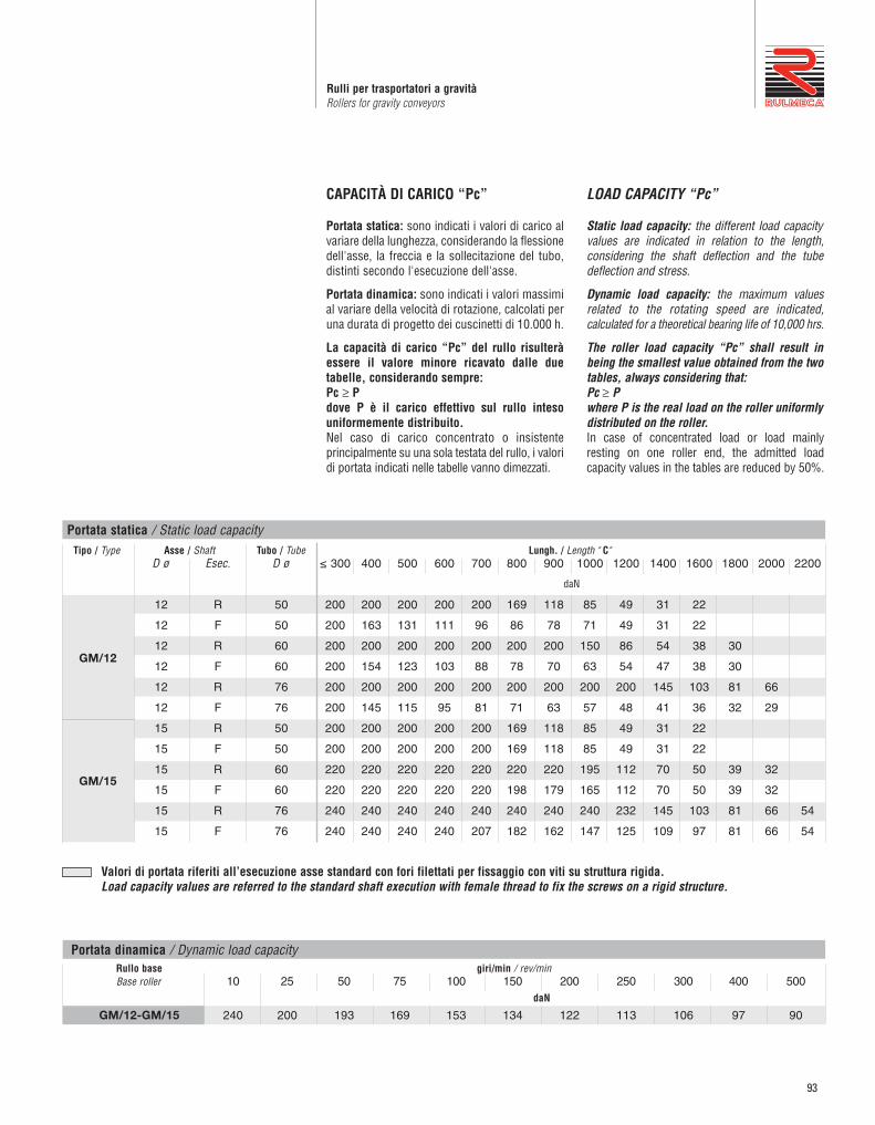
93
Rulli per trasportatori a gravitàRollers for gravity conveyors
CAPACITÀ DI CARICO “Pc”
Portata statica: sono indicati i valori di carico alvariare della lunghezza, considerando la flessionedell'asse, la freccia e la sollecitazione del tubo,distinti secondo l'esecuzione dell'asse.
Portata dinamica: sono indicati i valori massimial variare della velocità di rotazione, calcolati peruna durata di progetto dei cuscinetti di 10.000 h.
La capacità di carico “Pc” del rullo risulteràessere il valore minore ricavato dalle duetabelle, considerando sempre:Pc ≥ Pdove P è il carico effettivo sul rullo intesouniformemente distribuito.Nel caso di carico concentrato o insistenteprincipalmente su una sola testata del rullo, i valoridi portata indicati nelle tabelle vanno dimezzati.
LOAD CAPACITY “Pc”
Static load capacity: the different load capacityvalues are indicated in relation to the length,considering the shaft deflection and the tubedeflection and stress.
Dynamic load capacity: the maximum valuesrelated to the rotating speed are indicated,calculated for a theoretical bearing life of 10,000 hrs.
The roller load capacity “Pc” shall result inbeing the smallest value obtained from the twotables, always considering that:Pc ≥ Pwhere P is the real load on the roller uniformlydistributed on the roller.In case of concentrated load or load mainlyresting on one roller end, the admitted loadcapacity values in the tables are reduced by 50%.
Tipo / Type Asse / Shaft Tubo / Tube Lungh. / Length " C" D ø Esec. D ø ≤ 300 400 500 600 700 800 900 1000 1200 1400 1600 1800 2000 2200
12 R 50 200 200 200 200 200 169 118 85 49 31 22
12 F 50 200 163 131 111 96 86 78 71 49 31 22
12 R 60 200 200 200 200 200 200 200 150 86 54 38 30
12 F 60 200 154 123 103 88 78 70 63 54 47 38 30
12 R 76 200 200 200 200 200 200 200 200 200 145 103 81 66
12 F 76 200 145 115 95 81 71 63 57 48 41 36 32 29
15 R 50 200 200 200 200 200 169 118 85 49 31 22
15 F 50 200 200 200 200 200 169 118 85 49 31 22
15 R 60 220 220 220 220 220 220 220 195 112 70 50 39 32
15 F 60 220 220 220 220 220 198 179 165 112 70 50 39 32
15 R 76 240 240 240 240 240 240 240 240 232 145 103 81 66 54
15 F 76 240 240 240 240 207 182 162 147 125 109 97 81 66 54
Portata statica / Static load capacity
daN
Rullo base giri/min / rev/min Base roller 10 25 50 75 100 150 200 250 300 400 500
GM/12-GM/15 240 200 193 169 153 134 122 113 106 97 90
Portata dinamica / Dynamic load capacity
Valori di portata riferiti all’esecuzione asse standard con fori filettati per fissaggio con viti su struttura rigida.Load capacity values are referred to the standard shaft execution with female thread to fix the screws on a rigid structure.
daN
GM/12
GM/15

94
SerieSeries RTL1
RULLI FOLLI PER TRASPORTO DI CARICHI MEDIIN AMBIENTI INTERNI ED ESTERNI,NORMALI, POLVEROSI, UMIDI ECORROSIVI
Sono rulli costituiti da tubo in acciaio speciale,bombato su testate - sedi cuscinetto in tecno -polimero termoplastico, con elevate proprietà dielasticità, ermeticità, resistenza sia meccanica chealla corrosione.Sono dotati di cuscinetti lubrificati a vita radialirigidi di precisione tipo 6202. La protezione ècostituita dalla tenuta MECA, labirinto radiale adoppio effetto con coperchietto in lamiera zincata,per un utilizzo anche in condizioni ambientalimediamente severe.L’asse in acciaio trafilato è previsto in esecuzionestandard forato e filettato, per fissaggio con vitiM10, oppure in alternativa con bussole d’estremitàmetalliche per attacco di chiave ch17.L’impiego è normalmente consentito con tem -perature ambiente da – 5° C a + 80° C. Le caratteristiche costruttive e i materiali impiegaticonferiscono a questa serie un’ottima bilanciaturae bassa resistenza all’avviamento. Su richiesta possono essere forniti anche con tuboe asse inox AISI 304.
Nell’indicare il codice di ordinazione vanno riportatiil tipo, il diametro e l’esecuzione asse, il diametro el’esecuzione tubo, la lunghezza “C”.
Esempi di codice di ordinazioneRTL/1 15R 76J 800RTL/1 15B 89N 258
Tutte le quote sono espresse in mm.
IDLE ROLLERS FOR MEDIUM UNIT HANDLING CONVEYORS ININTERNAL, EXTERNAL, NORMAL,DUSTY, HUMID AND CORROSIVEENVIRONMENTS
The rollers consist of a special steel tube swagedover the bearing housings which are made fromtechnopolymers having high elastic properties,sealing and resistance to mechanical forces andto corrosion.The standard design utilises radial precision ballbearings 6202, lubricated for life, protected bythe MECA sealing, a double radial labyrinth withzinc-plated cover cap to allow use in mediumsevere environmental conditions.The drawn steel standard shaft has standarddrilled and threaded execution for screws M10 oralternatively can have bushes ch17 .Application temperatures range from –5° C to+80° C.The construction features of the materialsemployed allow an excellent balancing and a lowstart resistance.Under request they can be supplied with AISI 304tube and shaft.
In indicating the ordering code, please specify thetype, the shaft diameter and execution, the tubediameter and execution, the “C” length.
Ordering code examplesRTL/1 15R 76J 800RTL/1 15B 89N 258
All dimensions are in mm.

95
Rulli folliIdler rollers
Legenda delle sigle di esecuzioneR = asse forato e filettatoB = asse con bussola ch17B14 = asse con bussola ch14I = asse in acciaio inox AISI 304
N = tubo acciaio normaleJ = tubo con zincatura elettroliticaZ = tubo in lamiera zincata a caldo (sendzimir)P = rivestimento con guaina morbida in PVCI = tubo in acciaio inox AISI 304
Execution codes captionR = drilled and threaded shaftB = shaft with bush ch17B14 = shaft with bush ch14I = stainless steel shaft AISI 304
N = normal steel tubeJ = zinc-plated tubeZ = hot dip zincplated tube (sendzimir)P = soft PVC laggingI = stainless steel AISI 304 tube
RTL/1 R N
60
76
89
80
2000
22008*
0,0425
0,0503
0,0568
1,01
1,19
1,36
0,7
0,9
1,1
0,0286
0,0365
0,0429
Tipo / Typed(ø) esec. D(ø) esec. min max
Tubo / Tube Esec. AsseShaft exec.
Esec. TuboTube exec.
Lungh. / Length C f C=200daN
al cmdaN
Peso rullo / Roller weight Peso parti rotanti / Rotating parts weightCodice di ordinazione / Ordering codes Opzioni / OptionsAsse / Shaft C=200
daNal cmdaN
* Su richiesta la quota f può essere prevista con iseguenti valori: 4 - 10 - 14 - 18.
* Under request the f dim. can be: 4 - 10 - 14 - 18.
Nota: questi rulli possono essere forniti in esecuzioneantistatica, a richiesta.Note: these rollers can be supplied in antistaticversion, on request.
15 B - B14 - I
Z-P-I
J-P-I
Tipo / Typed(ø) esec. D(ø) esec. C
Lungh. / LengthAsse / Shaft Tubo / Tube
15 B
60
76
89
N
258
233
323
258
243
388
308
258
458
323
308
488
388
323
508
388
558
608
708
608
708
708
958
958
758
RTL/1
Rulli a stock / Stock Rollers
ch
17
14
Esec.
B
B14
Esec. Asse B
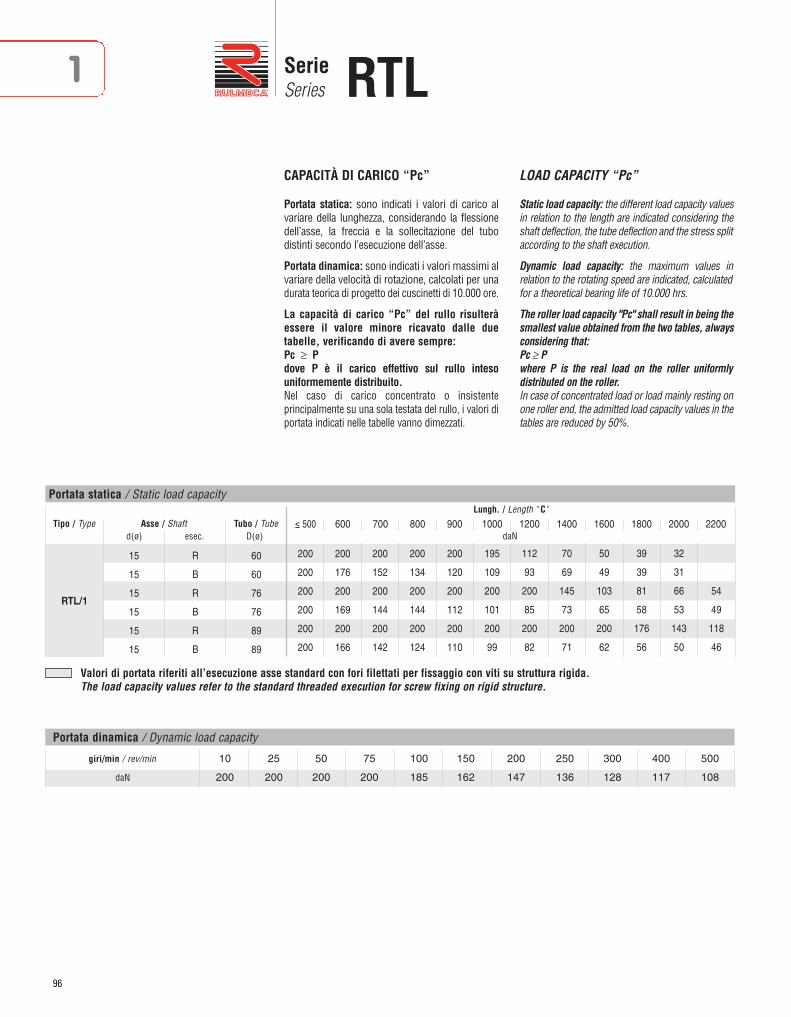
96
SerieSeries RTL1
Tipo / Typed(ø) esec. D(ø)
Tubo / TubeAsse / Shaft
ESECUZIONI ASSI A RICHIESTA / SHAFT EXECUTION ON REQUEST
RTL/1
200
200
200
200
200
200
200
176
200
169
200
166
200
152
200
144
200
142
200
134
200
144
200
124
200
120
200
112
200
110
195
109
200
101
200
99
112
93
200
85
200
82
70
69
145
73
200
71
50
49
103
65
200
62
39
39
81
58
176
56
32
31
66
53
143
50
54
49
118
46
≤ 500 600 700 800 900 1000 1200 1400 1600 1800 2000 2200
60
60
76
76
89
89
15
15
15
15
15
15
R
B
R
B
R
B
CAPACITÀ DI CARICO “Pc”
Portata statica: sono indicati i valori di carico alvariare della lunghezza, considerando la flessionedell’asse, la freccia e la sollecitazione del tubodistinti secondo l’esecuzione dell’asse.
Portata dinamica: sono indicati i valori massimi alvariare della velocità di rotazione, calcolati per unadurata teorica di progetto dei cuscinetti di 10.000 ore.
La capacità di carico “Pc” del rullo risulteràessere il valore minore ricavato dalle duetabelle, verificando di avere sempre:Pc ≥ Pdove P è il carico effettivo sul rullo intesouniformemente distribuito.Nel caso di carico concentrato o insistenteprincipalmente su una sola testata del rullo, i valori diportata indicati nelle tabelle vanno dimezzati.
LOAD CAPACITY “Pc”
Static load capacity: the different load capacity valuesin relation to the length are indicated considering theshaft deflection, the tube deflection and the stress splitaccording to the shaft execution.
Dynamic load capacity: the maximum values inrelation to the rotating speed are indicated, calculatedfor a theoretical bearing life of 10.000 hrs.
The roller load capacity "Pc" shall result in being thesmallest value obtained from the two tables, alwaysconsidering that:Pc ≥ Pwhere P is the real load on the roller uniformlydistributed on the roller.In case of concentrated load or load mainly resting onone roller end, the admitted load capacity values in thetables are reduced by 50%.
Portata statica / Static load capacity
giri/min / rev/min 10 25 50 75 100 150 200 250 300 400 500
daN 200 200 200 200 185 162 147 136 128 117 108
Portata dinamica / Dynamic load capacity
Valori di portata riferiti all’esecuzione asse standard con fori filettati per fissaggio con viti su struttura rigida.The load capacity values refer to the standard threaded execution for screw fixing on rigid structure.
daN
Lungh. / Length " C"

97
Rulli folliIdler rollers

98
SerieSeries MP-MPR1
RULLI FOLLI PER TRASPORTO DI CARICHI MEDI E PESANTI IN AMBIENTI INTERNI ED ESTERNI, NORMALI, POLVEROSI E UMIDI
Sono rulli in acciaio con tubo bombato, alleestremità, che garantiscono un perfetto accop -piamento con le sedi dei cuscinetti calibrate ISO M7.I cuscinetti a sfere a lubrificazione permanentesono del tipo radiale rigido di precisione 6202.Sono protetti dalla tenuta MECA, costituita da unlabirinto radiale a doppio effetto in Poliammide,alloggiato in un coperchietto di lamiera zincato,che consente l’impiego di questi rulli anche incondizioni ambientali severe.L’asse in acciaio trafilato è forato e filettato perfissaggio con viti nell’esecuzione standard, op -pure in alternativa è dotato di bussole d’estre -mità per attacco di chiave ch=17.L’impiego è normalmente consentito con tem -perature ambiente da –20° C a +100° C.Le caratteristiche costruttive rendono questi rullirobusti e affidabili anche ad alte velocità.
Nell’indicare il codice di ordinazione vanno ripor -tati il tipo, il diametro e l’esecuzione dell’asse, ildia metro e l’esecuzione tubo, la lunghezza “C”.
Esempi di codice di ordinazioneMP/15 15R 76J 800MPR/15 15B 89N 1000
Tutte le quote sono espresse in mm.
IDLE ROLLERS FOR MEDIUM AND HEAVY UNIT HANDLINGCONVEYORS IN INTERNAL, EXTERNAL,NORMAL, DUSTY AND HUMIDENVIRONMENTS
These steel rollers have a tube swaged over ateither end, which guarantees a perfect assemblywith the ISO M7 precision finished bearinghousings.The life lubricated ball bearings are of radialprecision 6202. The MECA sealing system,further improved, is composed by a Polyamidecentrifugal labyrinth housed in a zinc-plate thatallows the rollers to be employed even inparticular severe environments.The drawn steel shaft is internally threaded forscrew fixing or alternatively can have bushesch=17. Application temperatures range from –20° C to + 100° C. The construction features make the rollers strongand suitable for high speeds.
In indicating the ordering code, please specify thetype, the shaft diameter and execution, the tubediameter and execution, the “C” length.
Ordering code examples MP/15 15R 76J 800MPR/15 15B 89N 1000
All dimensions are in mm.

99
Rulli per trasportatori a gravitàRollers for gravity conveyors
MP/15
MPR/15
R N
60
76
89
60
76
89
80
N 80
2000
2200
2200
2
3
8*
8*
0,043
0,050
0,057
0,056
0,068
0,078
1,18
1,38
1,58
1,43
1,70
1,96
0,88
1,08
1,28
1,12
1,40
1,66
0,029
0,036
0,043
0,042
0,054
0,064
Tipo / Typed(ø) esec. D(ø) esec. min max
Tubo / Tube Esec. AsseShaft Exec.
Esec. TuboTube Exec.
Lungh. / Length C s f C=200daN
al cmdaN
Peso rullo / Roller weight Peso parti rotanti / Rotating parts weightCodice di ordinazione / Ordering codes Opzioni / OptionsAsse / Shaft C=200
daNal cmdaN
15
R15
B - B14
B - B14
Z-P
J-P
J-P
Legenda delle sigle di esecuzioneR = asse forato e filettatoB = asse con bussola ch17B14 = asse con bussola ch14
N = tubo acciaio normaleJ = tubo con zincatura elettroliticaZ = tubo in lamiera zincata a caldo (sendzimir)P = rivestimento con guaina morbida in PVC
Execution codes captionR = drilled and threaded shaftB = shaft with bush ch17B14 = shaft with bush ch14
N = normal steel tubeJ = zinc-plated tubeZ = hot dip zincplated tube (sendzimir)P = soft PVC lagging
*Su richiesta la quota f può essere prevista con iseguenti valori: 4 - 10 - 14 - 18.
*Under request the f dim. can be: 4 - 10 - 14 - 18.
ch
17
14
Esec.
B
B14
Esec. Asse B

100
SerieSeries MP-MPR1
Tipo / Typed(ø) esec. D(ø)
Tubo / TubeAsse / Shaft
ESECUZIONI ASSI A RICHIESTA / SHAFT EXECUTION ON REQUEST
MP/15
250
250
250
250
250
250
250
250
250
250
250
250
250
250
250
250
250
250
250
176
250
169
250
166
250
134
250
126
250
124
195
109
250
101
250
99
112
93
232
85
250
82
70
69
145
73
250
71
50
49
103
65
224
62
39
39
81
58
176
56
32
31
66
53
143
50
54
49
118
46
≤ 200 300 400 600 800 1000 1200 1400 1600 1800 2000 2200
60
60
76
76
89
89
15
15
15
15
15
15
R
B
R
B
R
B
CAPACITÀ DI CARICO “Pc”
Portata statica: sono indicati i valori di carico alvariare della lunghezza, considerando la flessionedell’asse, la freccia e la sollecitazione del tubo,distinti secondo l’esecuzione dell’asse.
Portata dinamica: sono indicati i valori massimi alvariare della velocità di rotazione, calcolati per unadurata teorica di progetto dei cuscinetti di 10.000 ore.
La capacità di carico “Pc” del rullo risulteràessere il valore minore ricavato dalle duetabelle, verificando di avere sempre:Pc ≥ Pdove P è il carico effettivo sul rullo intesouniformemente distribuito.Nel caso di carico concentrato o insistente princi pal -mente su una sola testata del rullo, i valori di portataindicati nelle tabelle vanno dimezzati.
LOAD CAPACITY “Pc”
Static load capacity: the different load capacity valuesin relation to the length, are indicated considering theshaft deflection, the tube deflection and the stress splitaccording to the shaft execution.
Dynamic load capacity: the maximum values inrelation to the rotating speed are indicated, calculatedfor a theoretical bearing life of 10.000 hrs.
The roller load capacity "Pc" shall result in being thesmallest value obtained from the two tables, alwaysconsidering that:Pc ≥ Pwhere P is the real load on the roller uniformlydistributed on the roller.In case of concentrated load or load mainly resting onone roller end, the admitted load capacity values in thetables are reduced by 50%.
Portata statica / Static load capacity
daN
Lungh. / Length " C"
Valori di portata riferiti all’esecuzione asse standard con fori filettati per fissaggio con viti su struttura rigida.The load capacity values refer to the standard threaded execution for screw fixing on rigid structure.

101
Rulli per trasportatori a gravitàRollers for gravity conveyors
giri/min / rev/min Rullo base / Base Roller 10 25 50 75 100 150 200 250 300 400 500
MP/15 250 250 233 204 185 162 147 136 128 117 108
MPR/15 360 294 233 204 185 162 147 136 128 117 108
Portata dinamica / Dynamic load capacity
Valori di portata riferiti all’esecuzione asse standard con fori filettati per fissaggio con viti su struttura rigida.The load capacity values refer to the standard threaded execution for screw fixing on rigid structure.
daN
Tipo / Typed(ø) esec. D(ø)
Tubo / TubeAsse / Shaft
ESECUZIONI ASSI A RICHIESTA / SHAFT EXECUTION ON REQUEST
MPR/15
360
360
360
360
360
360
360
359
360
355
360
353
360
262
360
257
360
256
360
129
360
124
360
165
360
129
360
124
360
122
278
104
360
99
360
97
159
88
335
83
360
81
100
77
210
71
360
71
71
69
149
63
325
61
56
55
117
56
256
54
45
45
95
51
207
49
37
37
78
47
170
45
≤ 200 300 400 600 800 1000 1200 1400 1600 1800 2000 2200
60
60
76
76
89
89
15
15
15
15
15
15
R
B
R
B
R
B
Portata statica / Static load capacity
daN
Lungh. / Length " C"

102
SerieSeries MPS1
RULLI FOLLI PER TRASPORTO DICARICHI MEDI E PESANTI IN AMBIENTIINTERNI ED ESTERNI, NORMALI,POLVEROSI E UMIDI
Sono rulli in acciaio robusti e di qualità, impiegatida oltre 40 anni nei più importanti impianti ditrasporto a nastro, giustificando il loro impiegoanche nei trasporti industriali con cattive condizioniambientali. Le sedi dei cuscinetti, calibrate ISO M7,sono saldate all’estremità del tubo formando unastruttura monolitica (UNIBLOC).I cuscinetti, a sfere a lubrificazione permanente,sono del tipo radiale rigido di precisione 6202.La protezione stagna dei cuscinetti è garantita dallatenuta MECA, costituita da labirinto radiale adoppio effetto contenuto in un coperchietto dilamiera zincata, e da un fondello interno che as -sicura un’ampia camera di grasso.L’asse in acciaio trafilato e calibrato è forato efilettato per fissaggio con viti nell’esecuzionestandard M10, oppure in alternativa è dotato dibussole d’estremità metalliche per attacco dichiave ch17.L’impiego è normalmente consentito con tem -perature ambiente da –20°C a +100°C.Robustezza, equilibratura, bassa resistenza al l’av -viamento e affidabilità sono prerogative pe culiari diquesti rulli.
Nell’indicare il codice di ordinazione vanno riportatiil tipo, il diametro e l’esecuzione asse, il diametro el’esecuzione tubo, la lunghezza “C”.
Esempi di codice di ordinazioneMPS/1 15R 89N 800MPS/1 15B 76N 758
Tutte le quote sono espresse in mm.
IDLE ROLLERS FOR MEDIUM ANDHEAVY UNIT HANDLING CONVEYORSIN INTERNAL, EXTERNAL, NORMAL,DUSTY AND HUMID ENVIRONMENTS
The MPS rollers have been employed for morethan 40 years in the most important beltconveyor applications, enhancing their use in thesevere environmental conditions in industrialhandling systems as well. The end-caps, gauged to ISO M7, are welded tothe tube forming a monolithic structure (UNIBLOC).The permanently lubricated are precision radialrigid ball bearings 6202 type. The sealing systemis guaranteed by the MECA sealing, composed bythe metallic cover, the centrifugal labyrinth sealand by the internal cap which retains a bigquantity of grease.The steel drawn shaft has a standard drilled andthreaded execution M10 for screw fixing oralternatively has metallic bush ch17.The application temperatures range from –20° Cto + 100° C. The perfect balancing, the low start resistance,the strength and suitability to high speedapplications are the main features of the series.
In indicating the ordering code, please specify thetype, the shaft diameter and execution, the tubediameter and execution, the “C” length.
Ordering code examples MPS/1 15R 89N 800MPS/1 15B 76N 758
All dimensions are in mm.

103
Rulli per trasportatori a gravitàRollers for gravity conveyors
MPS/3
MPS/1 R N
38
50
60
76
89
102
100
1600
1600
80NR15
2400
2,6
3
10*
8*
0,039
0,047
0,056
0,068
0,078
0,087
0,950
1,248
1,535
1,843
2,098
2,359
0,670
0,968
1,133
1,436
1,685
1,988
0,025
0,033
0,042
0,054
0,064
0,087
Tipo / Typed(ø) esec. D(ø) esec. min max
Tubo / Tube Esec. AsseShaft exec.
Esec. TuboTube exec.
Lungh. / Length C s f C=200daN
al cmdaN
Peso rullo / Roller weight Peso parti rotanti / Rotating parts weightCodice di ordinazione / Ordering codes Opzioni / OptionsAsse / Shaft C=200
daNal cmdaN
15B
B14 J-P
Legenda delle sigle di esecuzioneR = asse forato e filettatoB = asse con bussola ch17B14 = asse con bussola ch14
N = tubo acciaio normaleJ = tubo con zincatura elettroliticaP = rivestimento con guaina morbida in PVC
Execution codes captionR = drilled and threaded shaftB = shaft with bush ch17B14 = shaft with bush ch14
N = normal steel tubeJ = zinc-plated tubeP = soft PVC lagging
* Su richiesta la quota f può essere prevista con iseguenti valori: 4 - 10 - 14 - 18, escluso diametro38 che può prevedere valori: 6,5 - 12 - 16 - 20.
* Under request the f dim. can be: 4 - 10 - 14 - 18,excluding the 38 diameter that can have values:6,5 – 12 – 16 – 20.
MPS/3 Ø 38
MPS/1Esec. R

104
SerieSeries MPS1
MPS/1
MPS/1
B NNormali
Normal
Zincati
Zincplated
J
60
76
89
60
76
89
208
208
208
208
258
243
243
221
221
408
323
258
248
243
238
508
608
323
258
258
243
608
708
308
277
248
758
758
323
308
258
958
388
323
277
408
360
308
488
508
323
508
608
388
608
708
508
708
758
608
758
808
708
808
958
758
958
808
1158
958 1158
Tipo / Typed(ø) esec. D(ø) esec.
Tubo / Tube Lungh. / LengthC
Asse / Shaft
15
B15
MPS/3 Ø 38
MPS/1Esec. B
Rulli a stock / Stock rollers
ch
17
14
Esec.
B
B14
ch
17
14
Esec.
B
B14

105
Rulli per trasportatori a gravitàRollers for gravity conveyors
Tipo / Typed(ø) esec. D(ø)
Tubo / TubeAsse / Shaft
ESECUZIONI ASSI A RICHIESTA / SHAFT EXECUTION ON REQUEST
MPS/1
MPS/3
360
360
360
360
360
360
360
360
360
360
250
250
360
360
360
359
360
355
360
353
360
352
250
250
360
269
360
262
360
257
360
256
360
255
250
250
360
180
360
172
360
167
360
165
360
164
250
188
308
137
360
129
360
124
360
122
360
122
116
113
156
113
278
104
360
99
360
97
360
97
59
57
90
88
159
88
335
83
360
81
360
80
34
33
56
55
100
77
210
71
360
70
360
69
21
21
40
39
71
69
149
63
325
61
360
60
20
15
56
55
117
56
256
54
360
53
45
45
95
51
207
49
315
48
37
37
78
47
170
45
260
44
≤ 200 300 400 600 800 1000 1200 1400 1600 1800 2000 2200
50
50
60
60
76
76
89
89
102
102
38
38
15
15
15
15
15
15
15
15
15
15
15
15
R
B
R
B
R
B
R
B
R
B
R
B
CAPACITÀ DI CARICO “Pc”
Portata statica: sono indicati i valori di carico alvariare della lunghezza, considerando la flessionedell’asse, la freccia e la sollecitazione del tubodistinti secondo l’esecuzione dell’asse.
Portata dinamica: sono indicati i valori massimi alvariare della velocità di rotazione, calcolati per unadurata teorica di progetto dei cuscinetti di 10.000 ore.
La capacità di carico “Pc” del rullo risulteràessere il valore minore ricavato dalle duetabelle, verificando di avere sempre:Pc ≥ Pdove P è il carico effettivo sul rullo intesouniformemente distribuito.Nel caso di carico concentrato o insistenteprincipalmente su una sola testata del rullo, i valoridi portata indicati nelle tabelle vanno dimezzati.
LOAD CAPACITY “Pc”
Static load capacity: the different load capacity valuesin relation to the length are indicated considering theshaft deflection, the tube deflection and the stress splitaccording to the shaft execution.
Dynamic load capacity: the maximum values inrelation to the rotating speed are indicated, calculatedfor a theoretical bearing life of 10.000 hrs.
The roller load capacity "Pc" shall result in being thesmallest value obtained from the two tables, alwaysconsidering that:Pc ≥ Pwhere P is the real load on the roller uniformlydistributed on the roller.In case of concentrated load or load mainly resting onone roller end, the admitted load capacity values in thetables are reduced by 50%.
Portata statica / Static load capacity
giri/min / rev/min Rullo base / Base Roller 10 25 50 75 100 150 200 250 300 400 500
MPS/1 360 294 234 204 185 162 147 137 129 117 108
MPS/3 250 250 193 169 153 134 122 113 106 97 90
Portata dinamica / Dynamic load capacity
Valori di portata riferiti all’esecuzione asse standard con fori filettati per fissaggio con viti su struttura rigida.The load capacity values refer to the standard threaded execution for screw fixing on rigid structure.
daN
daN
Lungh. / Length " C"

106
SerieSeries 1191
RULLI FOLLI PER TRASPORTO DI CARICHI PESANTI IN AMBIENTI INTERNI NORMALI
Sono rulli molto scorrevoli in rapporto ai carichiammessi, e si combinano perfettamente con irulli comandati serie 139I cuscinetti sono alloggiati in sedi di Poliammidecolor nero; sono del tipo radiale rigido serie6205-2RZ a lubrificazione permanente, protettida coperchietti in Polipropilene di color giallo. Il tubo D.80-89 in acciaio è bombatoall’estremità, garantendo un perfettoaccoppiamento con le sedi dei cuscinetti. L’asse d.20 standard è forato e filettato perfissaggio con viti, che assicura un facilemontaggio e l’irrigidimento della strutturaLa particolare forma delle testate, l’accuratezzadegli accoppiamenti e il tipo di cuscinettiimpiegati rendono questi rulli funzionali ancheper trasportatori comandati e a nastro, pure adalte velocità.L’impiego è normalmente consentito pertemperature ambiente da –5° C a +80; pertemperature diverse è necessario verificare lecondizioni di impiego.
Consigliamo di attenersi all’esecuzione standard;per esecuzioni a richiesta si prega di indicare nelseguente ordine: il tipo, il diametro el’esecuzione asse, il diametro e l’esecuzionetubo, la lunghezza “C”.
Esempi di codice di ordinazione119/20 20R 80N 900119/45 20R 89J 1000
Tutte le quote sono espresse in mm.
IDLE ROLLERS FOR HEAVY UNITHANDLING CONVEYORS IN NORMALINTERNAL ENVIRONMENTS
These very smooth running rollers in relation tothe load capacity are suited to be combined withthe driven series 139.The permanently lubricated precision ballbearings 6205-2RZ are housed in black colourPolyamide end caps and protected by yellowcolour Polypropylene caps. The swaged steel tube D.80-89 guarantees aperfect assembly with the end caps.The standard shaft d.20 is internally threaded forscrew fixing and makes easy assembly morerigid and strong.The particular shape of the end-caps, theaccuracy of the assembly and the type of bearingsemployed make these rollers suitable also fordriven and belt conveyor high speed applicationsin industrial systems.Application temperatures range from –5° C to+80° C; working conditions must be verified forapplications in different temperatures.
We suggest conforming to the standardexecutions; for different executions pleasespecify: the type, the shaft diameter andexecution, the tube diameter and execution, the“C” length.
Ordering code examples119/20 20R 80N 900119/45 20R 89J 1000
All dimensions are in mm.

107
Rulli per trasportatori a gravitàRollers for gravity conveyors
119/20
119/45R N
80
80
89
80 2400
2
35
0,063
0,081
0,088
1,530
1,880
2,005
0,997
1,348
1,472
0,039
0,057
0,064
J-P-IF-J-I
Tipo / Typed(ø) esec. D(ø) esec. min max
Tubo / Tube Esec. AsseShaft Exec.
Esec. TuboTube Exec.
Lungh. / Length C s f C=200daN
al cmdaN
Peso / Weight Peso parti rotanti / Rotating parts weightCodice di ordinazione / Ordering codes Opzioni / OptionsAsse / Shaft C=200
daNal cmdaN
20
Legenda delle sigle di esecuzioneR = asse forato e filettatoF = asse con chiave fresataJ = asse con zincatura elettroliticaI = asse in acciaio inox AISI 304
N = tubo in acciaio normaleJ = tubo con zincatura elettroliticaP = tubo con guaina morbida in PVCI = tubo in acciaio inox AISI 304
Execution codes captionR = drilled and threaded shaftF = milled shaft with slotsJ = zinc-plated shaftI = stainless steel shaft AISI 304
N = normal steel tubeJ = zinc-plated tubeP = soft PVC laggingI = stainless steel tube AISI 304
Nota:Questi rulli possono essere forniti:- in esecuzione antistatica
Note:These rollers can be supplied:- in antistatic version
F
dExec. ch e g
F17
F15
20
14
17
15
5 9
Esec. F

108
SerieSeries 1191
CAPACITÀ DI CARICO “Pc”
Portata statica: sono indicati i valori di carico alvariare della lunghezza, considerando la flessionedell’asse, la freccia e la sollecitazione del tubo.
Portata dinamica: sono indicati i valori di caricomassimi dei cuscinetti al variare della velocità dirotazione, calcolati per una durata di progetto di10.000 ore.
La capacità di carico “Pc” del rullo risulteràessere il valore minore ricavato dalle duetabelle, considerando sempre:Pc ≥ Pdove P è il carico effettivo sul rullo intesouniformemente distribuito.
Nel caso di carico concentrato o insistenteprincipalmente su una sola testata del rullo, i valoridi portata indicati nelle tabelle vanno dimezzati.
LOAD CAPACITY “Pc”
Static load capacity: the different load capacity valuesin relation to the length are indicated considering theshaft deflection, the tube deflection and the stress.
Dynamic load capacity: the maximum bearing loadcapacity values in relation to the rotating speed areindicated, calculated for a theoretical bearing life of10,000 hrs.
The roller load capacity “Pc” shall result in beingthe smallest value obtained from the two tables,always considering that:Pc ≥ P
where P is the real load on the roller as uniformlydistributed.
In case of concentrated load or load mainly resting onone roller end, the admitted load capacity values in thetables are reduced by 50%.
Tipo / TypeD(ø) x s
Tubo / Tube
119/20
119/45
500
500
500
465
500
500
348
500
500
268
387
471
210
304
439
168
243
412
136
197
366
120
173
321
94
136
253
≤ 900 1000 1100 1200 1300 1400 1500 1600 1800
76
110
205
63
91
169
53
76
142
2000 2200 2400
80x2
80x3
89x3
ESECUZIONI ASSI A RICHIESTA / SHAFT EXECUTION ON REQUESTPortata Statica / Static Load CapacityLungh. / Length " C"
daN
10 25 50 75 100 150 200 250 300 400 500
500 500 500 472 429 375 341 316 298 270 251
Portata dinamica / Dynamic load capacity
giri/minuto / rev/min
daN

109
Rulli per trasportatori a gravitàRollers for gravity conveyors

110
SerieSeries PS1
RULLI FOLLIPER TRASPORTO DI COLLICON CARICHI PESANTI IN AMBIENTIINTERNI ED ESTERNI, NORMALI,POLVEROSI E UMIDI
Sono rulli di qualità e precisione.Le sedi dei cuscinetti calibrate ISO M7 sonosaldate all’estremità del tubo, formando unastruttura monolitica (UNIBLOC).I cuscinetti a sfera radiali rigidi delle migliorimarche sono della serie 6204-6205-6206-6308con lubrificazione permanente.La protezione dei cuscinetti è garantita all'esternodal labirinto multiplo centrifugo con coperchiettocombinato con la bussola esterna (contact-less),mentre all'interno un fondello costituisce un'ampiacamera di grasso. Il tutto è realizzato in materialetermoplastico anticorrosione. L'asse è in acciaio rettificato, con fori filettati perfissaggio con viti, o in alternativa fresato perattacco di chiave.L’impiego è normalmente consentito con tempe -rature ambiente da -20°C a +100°C.Elevata robustezza, equilibratura e coassialità,minima resistenza all’avviamento, precisione eaffidabilità contraddistinguono questa serie.
Nell’indicare il codice di ordinazione vanno riportatiil tipo, il diametro e l’esecuzione dell’asse, il diame -tro e l’esecuzione del tubo, la lunghezza “C”.
Esempi di codice di ordinazionePS/20 20R 89J 800PS/20 20F 89N 900
Tutte le quote sono espresse in mm.
IDLE ROLLERSFOR HEAVY PALLET CONVEYORS IN INTERNAL, EXTERNAL, NORMAL,DUSTY AND HUMID ENVIRONMENTS
These are quality precision rollers.The end-caps, gauged to ISO M7, are welded tothe tube forming a monolithic structure (UNIBLOC).The permanently lubricated radial rigid ballbearings are of the 6204-6205-6206-6308 series,of the best brands.The bearing protections are guaranteed by amultiple centrifugal labyrinth with cover capcombined with external cap (contact-less), whilean internal seal retains a big quantity of grease.All parts are made of anticorrosive thermoplasticmaterials.The ground steel shaft is internally threaded forscrew fixing or have a slot execution.The application temperatures range from -20° Cto + 100° C. This series features high strength, perfectbalancing and concentricity, minimum startingresistance, precision and suitability.
In indicating the ordering code, please specify thetype, the shaft diameter and execution, the tubediameter and execution, the “C” length.
Ordering code examplesPS/20 20R 89J 800PS/20 20F 89N 900
All dimensions are in mm.

111
Rulli per trasportatori a gravitàRollers for gravity conveyors
PS/20
PS/25
PS/30
PS/40
R N
60
76
89
102
108
133
89
108
133
159
89
108
133
159
133
159
194
130
N 140
N 145
N 170
2400
2600
2600
2800
2800
2800
2800
2800
3000
3000
2800
2800
3000
3000
3000
3000
3000
3
3
3
3
3,5
4
3
3,5
4
4,5
3
3,5
4
4,5
4
4,5
6,3
6204
6205
6206
6308
13 12 x 20
16 x 25
16 x 25
16 x 25
16
16
16
0,067
0,079
0,089
0,098
0,115
0,152
0,093
0,129
0,166
0,021
0,120
0,146
0,183
0,287
0,226
0,270
0,390
2,504
2,926
3,125
3,462
3,868
4,960
3,739
4,442
5,674
7,003
5,049
5,852
7,225
10,300
8,323
9,677
12,979
1,950
2,375
2,572
2,910
3,315
4,406
2,870
3,574
4,809
6,137
3,804
4,612
5,983
9,056
6,036
7,389
10,692
0,042
0,054
0,064
0,073
0,091
0,127
0,064
0,091
0,127
0,172
0,064
0,091
0,127
0,172
0,127
0,171
0,291
Tipo / Typed(ø) esec. D(ø) esec. min max
Tubo / Tube Esec. AsseShaft Exec.
Esec. TuboTube Exec.
Lungh. / Length C sCuscinettoBearing
f M C=200daN
al cmdaN
Peso rullo / Roller weight Peso parti rotanti Rotating parts weightCodice di ordinazione / Ordering codes Opzioni / Options
Asse / Shaft C=200daN
al cmdaN
20
R25
R30
R40
FF17
FF17
F
F
J-P
J
J-P
J
J-P
J
J
PS/40 Legenda delle sigle di esecuzioneR = asse forato e filettatoF = asse con chiave fresata
N = tubo acciaio normaleJ = tubo con zincatura elettroliticaP = rivestimento con guaina morbida in PVC
Execution codes captionR = drilled and threaded shaftF = shaft with slots obtained by milling
N = normal steel tubeJ = zinc-plated tubeP = soft PVC lagging
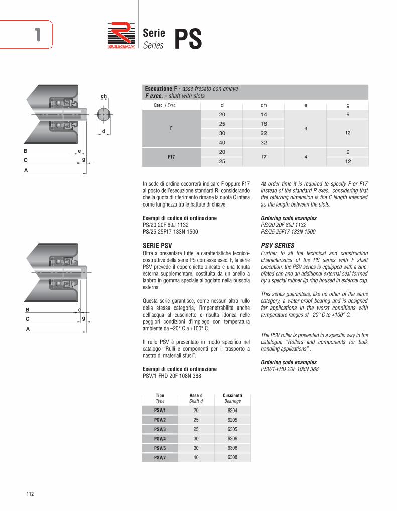
112
SerieSeries PS1
Esec. / Exec. d ch e g
20 14 9
25 18
30 22
40 32
20 9
25 12
Esecuzione F - asse fresato con chiaveF exec. - shaft with slots
F
F17
In sede di ordine occorrerà indicare F oppure F17al posto dell’esecuzione standard R, considerandoche la quota di riferimento rimane la quota C intesacome lunghezza tra le battute di chiave.
Esempi di codice di ordinazionePS/20 20F 89J 1132PS/25 25F17 133N 1500
SERIE PSVOltre a presentare tutte le caratteristiche tecnico-costruttive della serie PS con asse esec. F, la seriePSV prevede il coperchietto zincato e una tenutaesterna sup plementare, costituita da un anello alabbro in gomma speciale alloggiato nella bussolaesterna.
Questa serie garantisce, come nessun altro rullodella stessa categoria, l’impenetrabilità anchedell’acqua al cuscinetto e risulta idonea nellepeggiori condizioni d’impiego con temperaturaambiente da –20° C a +100° C.
Il rullo PSV è presentato in modo specifico nelcatalogo “Rulli e componenti per il trasporto anastro di materiali sfusi”.
Esempi di codice di ordinazionePSV/1-FHD 20F 108N 388
At order time it is required to specify F or F17instead of the standard R exec., considering thatthe referring dimension is the C length intendedas the length between the slots.
Ordering code examplesPS/20 20F 89J 1132PS/25 25F17 133N 1500
PSV SERIES Further to all the technical and constructioncharacteristics of the PS series with F shaftexecution, the PSV series is equipped with a zinc-plated cap and an additional external seal formedby a special rubber lip ring housed in external cap.
This series guarantees, like no other of the samecategory, a water-proof bearing and is designedfor applications in the worst conditions withtemperature ranges of –20° C to +100° C.
The PSV roller is presented in a specific way in thecatalogue “Rollers and components for bulkhandling applications” .
Ordering code examplesPSV/1-FHD 20F 108N 388
20
25
25
30
30
40
6204
6205
6305
6206
6306
6308
TipoType
Asse dShaft d
CuscinettiBearings
PSV/1
PSV/2
PSV/3
PSV/4
PSV/5
PSV/7
17
4
4
12
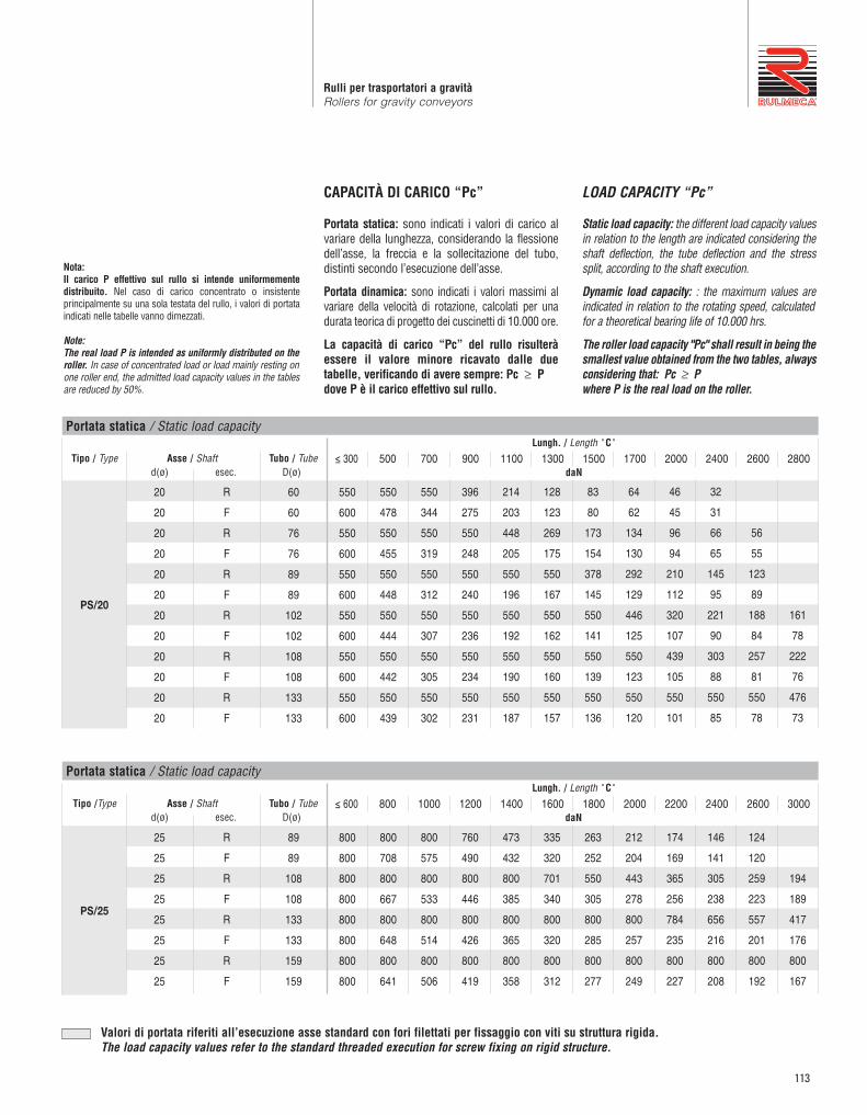
113
Rulli per trasportatori a gravitàRollers for gravity conveyors
Tipo / Typed(ø) esec. D(ø)
Tubo / TubeAsse / Shaft
PS/20
550
600
550
600
550
600
550
600
550
600
550
600
550
478
550
455
550
448
550
444
550
442
550
439
550
344
550
319
550
312
550
307
550
305
550
302
396
275
550
248
550
240
550
236
550
234
550
231
214
203
448
205
550
196
550
192
550
190
550
187
128
123
269
175
550
167
550
162
550
160
550
157
83
80
173
154
378
145
550
141
550
139
550
136
64
62
134
130
292
129
446
125
550
123
550
120
46
45
96
94
210
112
320
107
439
105
550
101
32
31
66
65
145
95
221
90
303
88
550
85
56
55
123
89
188
84
257
81
550
78
161
78
222
76
476
73
≤ 300 500 700 900 1100 1300 1500 1700 2000 2400 2600 2800
60
60
76
76
89
89
102
102
108
108
133
133
20
20
20
20
20
20
20
20
20
20
20
20
R
F
R
F
R
F
R
F
R
F
R
F
CAPACITÀ DI CARICO “Pc”
Portata statica: sono indicati i valori di carico alvariare della lunghezza, considerando la flessionedell’asse, la freccia e la sollecitazione del tubo,distinti secondo l’esecuzione dell’asse.
Portata dinamica: sono indicati i valori massimi alvariare della velocità di rotazione, calcolati per unadurata teorica di progetto dei cuscinetti di 10.000 ore.
La capacità di carico “Pc” del rullo risulteràessere il valore minore ricavato dalle duetabelle, verificando di avere sempre: Pc ≥ Pdove P è il carico effettivo sul rullo.
LOAD CAPACITY “Pc”
Static load capacity: the different load capacity valuesin relation to the length are indicated considering theshaft deflection, the tube deflection and the stresssplit, according to the shaft execution.
Dynamic load capacity: : the maximum values areindicated in relation to the rotating speed, calculatedfor a theoretical bearing life of 10.000 hrs.
The roller load capacity "Pc" shall result in being thesmallest value obtained from the two tables, alwaysconsidering that: Pc ≥ P where P is the real load on the roller.
Portata statica / Static load capacity
daN
Lungh. / Length " C"
Tipo /Typed(ø) esec. D(ø)
Tubo / TubeAsse / Shaft
ESECUZIONI ASSI A RICHIESTA / SHAFT EXECUTION ON REQUEST
PS/25
800
800
800
800
800
800
800
800
800
708
800
667
800
648
800
641
800
575
800
533
800
514
800
506
760
490
800
446
800
426
800
419
473
432
800
385
800
365
800
358
335
320
701
340
800
320
800
312
263
252
550
305
800
285
800
277
212
204
443
278
800
257
800
249
174
169
365
256
784
235
800
227
146
141
305
238
656
216
800
208
124
120
259
223
557
201
800
192
194
189
417
176
800
167
≤ 600 800 1000 1200 1400 1600 1800 2000 2200 2400 2600 3000
89
89
108
108
133
133
159
159
25
25
25
25
25
25
25
25
R
F
R
F
R
F
R
F
Portata statica / Static load capacity
daN
Lungh. / Length " C"
Valori di portata riferiti all’esecuzione asse standard con fori filettati per fissaggio con viti su struttura rigida.The load capacity values refer to the standard threaded execution for screw fixing on rigid structure.
Nota:Il carico P effettivo sul rullo si intende uniformementedistribuito. Nel caso di carico concentrato o insistenteprincipalmente su una sola testata del rullo, i valori di portataindicati nelle tabelle vanno dimezzati.
Note:The real load P is intended as uniformly distributed on theroller. In case of concentrated load or load mainly resting onone roller end, the admitted load capacity values in the tablesare reduced by 50%.

114
SerieSeries PS1
Tipo / Typed(ø) esec. D(ø)
Tubo / TubeAsse / Shaft
ESECUZIONI ASSI A RICHIESTA / SHAFT EXECUTION ON REQUEST
PS/30
1000
1000
1000
1000
1000
1000
1000
1000
1000
1000
1000
1000
1000
1000
1000
1000
760
715
1000
1000
1000
921
1000
887
473
449
989
894
1000
795
1000
760
335
320
701
670
1000
702
1000
666
263
252
550
528
1000
630
1000
593
212
204
443
427
952
574
1000
536
174
169
365
353
784
528
1000
490
146
141
305
296
656
490
1000
451
124
120
259
252
557
459
1000
419
107
104
223
217
479
432
926
391
417
407
805
367
≤ 800 1000 1200 1400 1600 1800 2000 2200 2400 2600 2800 3000
89
89
108
108
133
133
159
159
30
30
30
30
30
30
30
30
R
F
R
F
R
F
R
F
Portata statica / Static load capacity
daN
Lungh. / Length " C"
Tipo / Typed(ø) esec. D(ø)
Tubo / TubeAsse / Shaft
ESECUZIONI ASSI A RICHIESTA / SHAFT EXECUTION ON REQUEST
PS/40
2200
2200
2200
2200
2200
2200
2200
2200
2200
2200
2200
2200
2200
2200
2200
2049
2200
1946
2127
1958
2200
1765
2200
1659
1507
1439
2200
1557
2200
1449
1182
1135
2200
1398
2200
1287
952
918
1841
1273
2200
1160
784
758
1515
1172
2200
1056
656
637
1268
1090
2200
971
557
542
1077
1021
2200
899
479
467
926
902
2200
838
417
407
805
786
2021
786
≤ 800 1000 1200 1400 1600 1800 2000 2200 2400 2600 2800 3000
133
133
159
159
194
194
40
40
40
40
40
40
R
F
R
F
R
F
Portata statica / Static load capacity
daN
Lungh. / Length " C"
Valori di portata riferiti all’esecuzione asse standard con fori filettati per fissaggio con viti su struttura rigida.The load capacity values refer to the standard threaded execution for screw fixing on rigid structure.
Rullo base / Base Roller 10 25 50 75 100 150 200 250 300 400 500
PS/20 600 596 473 413 375 328 298 277 260 237 220
PS/25 800 744 591 516 469 410 372 346 325 295 274
PS/30 1000 935 821 717 651 569 517 480 452 410 381
PS/40 2200 2171 1723 1506 1368 1195 1086 1008 948 862 800
Portata dinamica / Dynamic load capacitygiri/min / rev/min
daN

115
Rulli per trasportatori a gravitàRollers for gravity conveyors

116
Rulli guidaGuide rollers
1
RULLI GUIDA (a sbalzo)
Questi rulli possono essere montati verticalmenteper il contenimento dei colli o come guida nastro,oppure a sbalzo orizzontalmente nei trasportatoricon applicazioni particolari. Nel codice di ordina -zione è indicata la lunghezza “B” standard allaquale sono riferiti la capacità di carico e il pesocomplessivo. Altre caratteristiche di questi rullicorrispondono a quelle della serie di appartenenza,con possibilità di diametro tubo diverso.
Esempi di codice di ordinazioneMPS/G7 15M14 60J 100GL/G2 10M 32Z 60
Tutte le quote sono espresse in mm.
GUIDE ROLLERS (cantilevered)
These rollers can be vertically installed fordirectional control, as belt guides or as horizontalcantilever in particular conveyor systems.Thestandard “B” length, to which the load capacityand total weight are referred, is indicated in theordering code. Other characteristics of theserollers correspond to those of the series to whichthey belong, with different tube diameters.
Ordering code exampleMPS/G7 15M14 60J 100GL/G2 10M 32Z 60
All dimensions are in mm.
GL/G2 GL/G4 GM/G2 RTL/G7 MPS/G1 MPS/G7 PSV/G7

117
Rulli per trasportatori a gravitàRollers for gravity conveyors
GL/G2
GL/G4
GM/G2
RTL/G7
RTL/G7
MPS/G1
MPS/G7
MPS/G7
MPS/G7
PSV/G7
M10
M12
M14
M14
M14
M14
M14
M14
M14
M16
Z
Z
Z
N
N
J
N
N
J
N
32
50
60
60
60
38
60
60
60
60
64*
84
84
88*
108*
88*
88*
108*
108*
108*
60
80
80
80
100
80
80
100
100
100
150
200
300
300
300
300
350
350
350
350
1,5
1,5
2
2
2
2,6
3
3
3
8
4
4
4
8
8
8
8
8
8
8
21,5
27,5
30,5
33
33
33
33
33
33
35
0,018
0,027
0,042
0,042
0,042
0,04
0,056
0,056
0,056
0,128
0,265
0,443
0,571
0,610
0,694
0,616
0,828
0,940
0,940
1,450
15
25
45
45
45
55
60
60
60
100
Tipo / Typed(ø) esec. D(ø) esec. Standard
Tubo / Tube Esec. TuboTube exec.
Lungh. / Length CStd. max
Lungh. / Length B s e g Std.daN
al cmdaN
Peso / Weight Capacità di carico Load capacity
daN
Codice di ordinazione / Ordering codes Opzioni / OptionsAsse / Shaft
10
12
14
14
14
14
14
14
14
16
M
10
12
15
15
15
15
15
15
15
20
N
N
N
Z
Z
N
J
J
N
J
Legenda delle sigle di esecuzioneM = asse con estremità filettateZ = tubo con zincatura a caldo (sendzimir)J = tubo con zincatura elettroliticaN = tubo in acciaio normale
Execution codes captionM = shaft with threaded endsZ = hot dip zinc (sendzimir)J = zinc-plated tubeN = normal steel tube
*Tipi disponibili a magazzino.*Types available at stock.

118
Esecuzioni tubo a richiestaTube executions on request
1
ESECUZIONI “E” e “F”Rulli con gole per trasmissione concinghie tonde
Per questo tipo di trasmissione si sono previstirulli folli con gole ricavate direttamente sul tuboin acciaio, soluzione molto semplice ed eco no mica.Le cinghie devono avere una sezione di Ø 4-5 mm.o al massimo Ø 8 mm.I rulli possono essere della serie GL, GM e 117,le cui caratteristiche sono presentate nel capitolo1, in esecuzione “E” (1 gola) o in esecuzione“F” (2 gole), con tubo in acciaio normale “N”,con zincatura elettrolitica “J” oppure conrivestimento in PVC “P”. Poiché la velocità di trasporto può essereelevata, anche se con carichi contenuti, occorreprestare particolare attenzione nella scelta deirulli in rapporto alle sollecitazioni dinamiche.
Codice di ordinazioneSi dovrà aggiungere le sigle “E” (1 gola) oppure“F” (2 gole) all’esecuzione del tubo del rulloprescelto.
Esempi:GL/12 12R 50JE 500GM/15 15R 76NEP 800117/12 12R 50JF 600
Tutte le quote sono espresse in mm.
Per maggiori dettagli vedere capitolo “Rulli pertrasportatori comandati a cinghie” pag. 207.
“E” and “F” EXECUTIONGrooved rollers for round beltstransmission
Idle rollers with grooves made directly on thesteel tube are intended for round beltstransmission as a very simple and economicalsolution. The belts should have a section of Ø 4-5 mm or max. Ø 8 mm. Rollers may be “GL, GM and 117” series, whosecharacteristics are described in chapter 1, inexecution “E” (1 groove) or in execution “F” (2grooves), with standard steel tube “N”, withelectrolytic zinc-plating “J” or PVC coating “P”.Since the handling speed may be high, eventhough with restrained loads, particular care shallbe taken in choosing the rollers in relation to theexpected dynamic stresses.
Ordering code The letter “E” (1 groove) or “F” (2 grooves) mustbe added to the tube execution of the selectedroller.
Examples:GL/12 12R 50JE 500GM/15 15R 76NEP 800117/12 12R 50JF 600
All dimensions are in mm.
For further details please refer to chapter “Rollersfor belt driven conveyors at page 207.
Tipo / Type D Di a b r
32 24 20 16 2,5
40 30 32 20 5
50 38 32 20 5
50 38 32 20 5
60 48 32 20 5
76 64 32 20 5
50 38 32 20 5
60 48 32 20 5
76 64 32 20 5
40 30 35 20 5
50 38 35 20 5
60 48 35 20 5
GL/60-62
GL/8
GL/10-11-12
GM/12-15
117/8-10-11-12
Nella versione con asse a molla le gole sono eseguite nel lato opposto alla compressione dell'asse. With spring shaft version, grooves are made on the roller size opposed to the shaft compression.

119
Rulli per trasportatori a gravitàRollers for gravity conveyors
ESECUZIONE “P”Rulli rivestiti con guaina in PVC
Pur non essendo speciale, diamo di seguitomaggiori informazioni su questa esecuzione.I rulli con tubo in acciaio grezzo “N” o zincato“Z e J” con i valori di diametro “D” secondotabella, possono essere ricoperti con una guainain PVC (Polivinilcloruro) morbida ed elastica(durezza 73 ShA) di colore grigio metallizzato(RAL 9006) e superficie liscia, particolarmenteresistente agli agenti chimici.Normalmente viene usata per proteggere lasuperficie del rullo e soprattutto per non rigare icolli trasportati con piani laccati, verniciati,lisciati ecc. e in alcuni casi per maggior attrito.La guaina viene semplicemente calzata sul tubocon ottimo accoppiamento per effetto di restrin -gimento elastico.
Temperature d’impiego da -10°C a +50°C.
Codice di ordinazioneSi dovrà aggiungere la sigla “P” all’esecuzione tubo.
Esempi:Rulli GL/12 12D 76NP 600Rulli 1700/10 10D 50ZP 500
Tutte le quote sono espresse in mm.
“P” EXECUTIONPVC covered rollers
Although not special, information on this designis given.The rough or zinc plated steel tube “N” or “Z andJ” rollers with “D” values as per table, can becovered with a soft, elastic and smooth surface(hardness 73 ShA) grey colour (RAL 9006) PVC (Polyvinylchloride) plastic tube, particularlyresistant to chemical agents.It is normally used to protect the roller surfacesand mostly to avoid scratching painted, enamelled,smooth, etc. load, and in some cases to increasefriction.The PVC lagging is simply fitted on the tube withexcellent coupling thanks to elastic tightening.
Application temperatures ranging from -10°C to+50°C.
Ordering code The “P” code should be added to the tube design.
Examples:Rollers GL/12 12D 76NP 600Rollers 1700/10 10D 50ZP 500
All dimensions are in mm.
D De Peso guaina / Coating weight ± 0,5 Bu=200 al cm daN daN
24 28 0,031 0,002
30 34 0,065 0,003
32 36 0,065 0,003
40 44 0,074 0,004
50 55 0,082 0,004
60 66 0,134 0,006
63 69 0,134 0,006
76 82 0,197 0,010
89 95 0,256 0,013
102 108 0,335 0,016
108 114 0,335 0,016

120
1 Esecuzioni tubo a richiestaTube executions on request
ESECUZIONE “W” e “H”Rulli con flange (dischi di contenimento)
Nei trasporti a gravità o motorizzati, dove è ne -ces sario guidare o contenere i colli movimentati,sono impiegati rulli con flange saldate sul tubo.Sono previsti tutti i rulli con tubo in acciaio condiametro “D” corrispondente alla tabella, con 1 flangia (esec. H) oppure 2 flange (esec. W).Per questa applicazione è prevista la possibilitàdi zincatura solo elettrolitica in esecuzione “J”.
Codice di ordinazioneSi dovrà aggiungere la sigla dell’esecuzione pre -scelta all’esecuzione tubo.
Esempi:Rulli GL/12 12D 60JH 900Rulli PS/S1 20R 89NW 1150
Tutte le quote sono espresse in mm.
“W” and “H” EXECUTIONSRollers with guide flanges
In gravity or driven conveyor systems, wherethe necessity arises to guide or contain thepackages handled, rollers, with welded flangeson the tube are employed.All rollers are with steel tube and diameter “D”as per corresponding table, with 1 flange (H exec.) or 2 flanges (W exec.).For this design, zinc plating is foreseen only in“J” execution.
Ordering code: The selected execution code should be added tothe tube execution design.
Examples:Rollers GL/12 12D 60JH 900Rollers PS/S1 20R 89NW 1150
All dimensions are in mm.
De D
Rulli con flange (dischi di contenimento) - esecuzioni W/H / Rollers with guide flange - W/H executions
D De t D1 α s Peso cad. flangia X Y Y I min. Weight for each flange daN 1C 2C Exec. W Exec. H
50 90 8 70 30 3 0,12 15 40 60 95 75
60 110 8,5 70 15 3 0,16 16 45 70 115 90
76 135 10 88 15 3 0,21 20 50 75 140 110
80 155 15 110 30 3 0,33 35 - - 160 125
89 155 15 110 30 3 0,30 25 60 80 160 130
89 155 17,5 110 30 4 0,44 30 65 85 160 130
P1C-P2C
1C-2C

121
Rulli per trasportatori a gravitàRollers for gravity conveyors
FLANGE IN ALLUMINIO
Per rulli D.76 e 89 sono previste flange in alluminiofornite separatamente in un unico kit, costituito dadue elementi completo di bulloni di fissaggiozincati, per consentire di posizionarle a piacere.
Attenzione:le viti vanno serrate con chiave dinamometrica concoppia ≤ 13 Nm.
Esempio descrizione:Flange D.89/150 alluminio kit 3018010900
ALUMINIUM FLANGES
For the rollers diameter 76 and 89 mm, aluminiumflanges are supplied separately in a special kit,composed by 2 elements and complete with zincplated fixing bolts to assemble them in different ways.
Attention:the screws must be tightened by torque wrench≤ 13 Nm.
Description example:Flanges D.89/150 aluminium kit 3018010900
Codice / Code D De D1 Kit Peso compl. rif. - ref. Total weight daN
SF_FLG.SPC-00004 76 130 90 3018010767 0,26
SF_FLG.SPC-00003 89 150 104 3018010900 0,28
HIGH FRICTION SLEEVES Where it is necessary to increase frictionbetween the rollers and the handled unit loadsthe employment of these sleeves are particularlyeffective. They are made with transparentPolyurethane 75 Sh.A with longitudinal groovesand are supplied separately only for rollers withtube Ø 50.
Code: SVGN-00050Description: Sleeves D.45/55 L=35
All dimensions are in mm.
MANICOTTI DI MAGGIOR ATTRITO Dove si rende necessario creare un attritomaggiore tra i rulli e i colli trasportati è partico -larmente efficace l’applicazione di questi mani -cotti. Sono realizzati in Poliuretano 75 Sh.A tra -spa rente a scanalatura longitudinale e ven gonoforniti sfusi, da montare per stretta inter ferenzasolo su rulli con tubo Ø50.
Codice: SVGN-00050Descrizione:Manicotti D.45/55 L=35
Tutte le quote sono espresse in mm.

122
1 Esecuzioni tubo a richiestaTube executions on request
ESECUZIONE “R”Rulli con rivestimento in gomma
Consiste nel rivestimento in gomma vulcanizzata(a caldo) antiabrasiva, durezza 70 ± 5 Sh.A, super -ficie tornita sp. 3 mm minimo.A richiesta il rivestimento può essere ottenuto condurezza o spessore diversi o con gomma incollatao Neoprene, Silicone ecc, compatibilmente con lequantità di rulli richiesti.
Codice di ordinazioneSi dovrà aggiungere la sigla R all’esecuzione tubodel rullo prescelto.
Esempio:Rulli PS/20 20R 89NR 950(indicare lo spessore del rivestimento se diversoda 3 mm)
ESECUZIONE “PU”Rulli con rivestimento in Poliuretano
Consiste nel rivestimento in Poliuretano, materialeparticolarmente resistente al taglio, usura eabrasione, durezza 90 ± 5 Sh.A, colore arancione.Durezza, colore e spessore possono essere forniticon altri valori su richiesta.
Codice di ordinazioneSi dovrà aggiungere la sigla PU all’esecuzionetubo del rullo prescelto.
Esempio:Rulli PS/25 25R 108NPU 700(indicare lo spessore del rivestimento se diversoda 5 mm)
ESECUZIONE “T”Rulli rilsanizzati
Consiste nella rilsanizzazione: trattamento a caldoa base di polveri di RILSAN, Poliammide, di colorgrigio chiaro, con particolari caratteristiche diresistenza agli agenti chimici e all’usura.
Codice di ordinazioneSi dovrà aggiungere la sigla T all’esecuzione tubodel rullo prescelto.
Esempio:Rulli MPS/1 15R 76NT 750
Tutte le quote sono espresse in mm.
“R” DESIGNRollers with rubber lagging
Lagging with 70 ± 5 Sh.A hardness, with surfaceturned to 3 mm minimum thickness.On request the lagging can be with differenthardnesses or thicknesses or with glued rubber,Adiprene, Neoprene and Silicone compatibilywith the number of rollers requested.
Ordering code:The “R” code should be added to the tube design.
Examples:Rollers PS/20 20R 89NR 950(please specify the lagging thickness if differentfrom 3 mm)
“PU” DESIGNRollers with Polyurethane lagging
Polyurethane lagging with 90 ± 5 Sh.A hardness,orange colour, a material which is particularlyresistant to cuts, wear and abrasion.Hardness, colour and thickness can be suppliedwith other values on request.
Ordering code:The “PU” code should be added to the tube design
Examples:Rollers PS/25 25R 108NPU 700(please specify the lagging thickness if differentfrom 5 mm)
“T” DESIGNRilsan coated rollers
Rilsan coated: heat treatment based on RilsanPolyamide powders of light grey colour, withparticular resistance characteristics to chemicalagents and wear.
Ordering code:The “T” code should be added to the tube design.
Examples:Rollers MPS/1 15R 76NT 750
All dimensions are in mm.

123

124

125
1
Componenti vari
Components
RotelleWheels
MinirailMinirail
MedirailMedirail
HeavyrailHeavyrail
Rotelle OWOW wheels
Sfere portantiBall transfer units
Regolatori di velocitàSpeed controllers
ProfiliProfiles
126
130
131
132
134
136
142
146

126
1 RotelleWheels
RSR 48
Sono rotelle metalliche zincate particolarmenterobuste, con piste di rotolamento cementate etemperate.
RSR 48
Zinc-plated metallic wheels particularly strong,with cemented and hardened rolling surfaces.
RSR 50
Sono rotelle a strisciamento in Poliammide dicolore rosso la corona esterna e colore nero ilmozzo; particolarmente indicate per ambienticorrosivi o con forti sgocciolamenti, nonché per ilsettore alimentare, anche come sostegno di nastriin acciaio con basse velocità.
RSR 50
Polyamide wheels with red coloured external ringand black hubs; particularly suitable for corrosive,damp and food environments, also as low speedbelt supports.
Tipo Portata Peso Type d Load capacity Weight
RSR 48 8,2 20 0,070
daN daN
Tipo Portata Peso Type d Load capacity Weight
RSR 50B 8,2 15 0,020
RSR 50C 10,2 15 0,019
RSR 50D 12,2 15 0,018
daN daN
ROTELLE SERIE RSR
Le rotelle vengono impiegate nei trasportatori agravità per applicazioni speciali in corrispondenzadi svincoli o come guida, oppure montate a gruppiin asse sia in tratti rettilinei che in curva.
WHEELS SERIES RSR
These wheels are used in gravity conveyors inspecial applications related to clearing sections,as guides or group mounted on the same spindlein straight or curved sections.

127
Componenti variComponents
RSR 130-131-135
Sono rotelle a due corone di sfere particolarmenterobuste e silenziose. La carcassa esterna e la gab -bia sono in Polipropilene di colore azzurro, mentreil mozzo di rotolamento è in acciaio zincato, ce -men tato e temprato.A richiesta sono fornibili con perno e sfere inox,con lo schermo color bianco.
RSR 130-131-135
Double race wheels particularly strong and noiseless.The external casing and the cage are in bluePolypropylene with zinc-plated and hardened hub.Under request we can supply them with stainlesssteel stud and balls, with white screen.
ANELLO IN GOMMA TIPO RSR 105
Può essere montato sulle rotelle sia RSR 48 cheRSR 130-131. È particolarmente indicato per iltrasporto di colli con superfici delicate o smaltateche comunque non devono essere rigate.
RSR 105 RUBBER RING
This rubber ring can be assembled on the RSP 48and RSR 130-131 wheels. This is particularlyindicated to handle delicate or enamelled surfacesthat must not be scratched.
RSR 130
RSR 131
RSR 135
6,5
8,2
8,2
20
20
20
0,020
0,024
0,024
standard
con sfere inox - with stainless steel balls
TipoType d
PortataLoad capacity
daN
PesoWeight
daN
NoteNotes

128
1 RotelleWheels
ASSI CON ROTELLE SERIE GRA
Sono previsti con rotelle RSR 48 e RSR 131distanziate fra di loro con tubetto in PVC.Possono essere preferiti ai rulli nei trasportatoria gravità, con particolare funzionalità nellecurve, per la movimentazione di colli a superficied’appoggio piana.Si consiglia l’esecuzione standard per potermontare gli assi con le rotelle sfalsate fra di loro,e la struttura portante con sostegno centrale.
WHEELED SHAFTS SERIES GRA
They are supplied with RSR 48 and RSR 131wheels with PVC tube spacing and they can bepreferred to the rollers in gravity conveyors withparticular curve functionality and to handlepackages having flat contact surfaces.We suggest using the standard execution for anassembly of shafts with offset wheels andcentral stand supporting structure.
Codice di ordinazione Rotelle PesoOrdering Codes Wheels Weight
Tipo LunghezzaType Lenght C N. daN
GRA/8 284 3 0,335
GRA/9 384 4 0,450
GRA/10 484 5 0,575
GRA/11 584 6 0,690
GRA/12 684 7 0,800
GRA/13 784 8 0,910
GRA/14 884 9 1,030
Codice di ordinazione Rotelle PesoOrdering Codes Wheels Weight
Tipo LunghezzaType Lenght C N. daN
GRA/58 284 3 0,200
GRA/59 384 4 0,265
GRA/60 484 5 0,345
GRA/61 584 6 0,415
GRA/62 684 7 0,480
GRA/63 784 8 0,545
GRA/64 884 9 0,615
Con rotelle RSR 48 / With wheels RSR 48 Con rotelle RSR 131 / With wheels RSR 131

129
Componenti variComponents
ROTELLE SERIE RSV 370
Sono rotelle con carcassa in polipropilene dicolore nero.Il cuscinetto è a 2 corone di sfere con perno inacciaio zincato, opportunamente ribassato e fi -let tato con taglio per cacciavite in modo da con -sentire un semplice e facile montaggio.Ideali per la movimentazione di colli sufficien -temente rigidi con larghezza fissa, queste rotellesono previste con bordino di contenimento esenza; senza bordino possono essere applicateanche verticalmente come guida di contenimento.
WHEELS RSV 370 SERIES
These wheels have Polypropylene casing, black .The bearing slides on two rows of balls over a zinc-plated steel stud which is suitablydepressed and threaded with a screw slot toenable a simple and easy assembly.These wheels are ideal to handle quite rigid andfixed packages and are supplied with or withouta containment rim; without rim they can be alsoinstalled vertically as control guides.
Tipo Portata Peso Note VersioneType Load Capacity Weight Notes Version
daN daN
RSV 370 0,048standard
con flangia/with flange
RSV 371 0,045 senza flangia/without flange
RSV 371 Senza flangia / Without flange RSV 370 Con flangia / With flange
10 max.

Minirail
130
1
MINIRAIL SERIE R121-R122
Il Minirail è costituito da una barra in profilatozincato a caldo con lunghezza standard 2997mm e da rotelle in poliammide montate a passo27 mm o multiplo.La portata di ogni rotella è di 3 daN cad, ma lacapacità di carico max del sistema è determinatadalla resistenza del profilo, in relazione allafreccia consentita e alla distanza fra gli appoggi,come rappresentato nel diagramma.Questi profili sono ideali per la movimentazione dicolli leggeri e medi e per la realizzazione di sistemidi stoccaggio e picking. Trovano ottima applicazionecome guide di scorrimento e contenimento neiprocessi di packaging, per realizzare piani diappoggio e trasferimento, abbinati a macchine perla lavorazione del vetro, dei pannelli in legno e inmolti altri casi.Su richiesta e per quantitativi minimi di 300 metripossono essere fornite barre con lunghezza Ldiversa dallo standard.
MINIRAIL SERIES R121-R122
The Minirail is made of a zinc-plated profiled rodwith a standard length of 2997 mm and ofPolyamide wheels assembled with a 27mm ormultiple of pitch.The load capacity of each wheel is 3 daN, but thesystem max. load capacity is determined by theprofile resistance in relation to the maximumallowable camber and to the distance in-between the supports, as shown in the diagram.These wheel tracks are ideal to handle light andaverage units to create warehouse and pickingareas.They have excellent application as sliding andcontaining guides in the packaging processes,to produce rest and transfer surfaces combinedwith machines for the glass, wood panelsproduction and for many other industries. On request and for a minimum quantity of 300meters, tracks with “L” length different from thestandard can be supplied.
Portata - Load capacity
Dist
anza
tra
i sup
porti
Dist
ance
bet
wee
n th
e su
ppor
ts
L (mm)
R12127
54
54
2,18
1,99
2,04
rotelle normali - standard wheels
rotelle con bordino - flanged wheels
TipoType P
LunghezzaLength
L
PesoWeight
daN
NoteNotes
R122
2997
2997
Barre standard a magazzino. - Standard stock rails.

131
PROFILO MEDIRAIL SERIE R127
Il profilo Medirail è stato progettato per montarecon estrema facilità le rotelle diametro 48 tipoRSR 48 in acciaio zincato, oppure tipo RSR 131in materia plastica (Polipropilene). Questosistema è la soluzione ideale per costituire corsiedi scorrimento a gravità di colli leggeri e medioppure per il contenimento laterale dei traspor -tatori. Inoltre trova ottima applicazione nei ma -gaz zini dinamici di stoc caggio e picking.La caratteristica dell’inserimento “a scatto” dellerotelle consente la facile sostituzione dellestesse, nonché un agevole accesso ai fori di fis -saggio; inoltre le rotelle risultano bloccate inmodo sicuro perfettamente appoggiate nellasede di alloggiamento.Il profilo Medirail è realizzato in lamiera zincata acaldo con lunghezza standard 2496 mm. e perun interasse delle rotelle di 52 mm. o multiplo. Èparticolarmente robusto, come si può rilevaredal diagramma che riporta la portata in rapportoalla distanza fra gli appoggi da confrontare conla capacità di carico delle rotelle impiegate.Il profilo Medirail può essere fornito conlunghezza diversa dallo standard, se la quantitàrichiesta lo giustifica.
MEDIRAIL PROFILE R127 SERIES
The Medirail profile has been designed for easyinstallation of the 48 mm. diameter galvanizedsteel wheels type RSR 48 or the plastic materialtype RSR 131.This system represents the ideal solution formedium and light units gravity lanes or forlateral containment of handling systems.Furthermore it is particularly suitable for pickingand stocking applications.The “click type” insertion characteristic allowsthe wheels to be easily changed and offers goodaccess to the fixing bores; furthermore thewheels result in being firmly blocked andperfectly housed in the supports.The Medirail profile is made of galvanized ironsheet with 2496 mm. standard length and with awheel pitch of 52 mm. or multiples. It isparticularly strong as it results from the diagramthat lists the load capacity in relation to thedistance between the supports to be comparedwith the wheel load capacities.The Medirail profile can be supplied in lengthsdifferent from the standard, if the quantitiesrequired justify it.
Nota: le rotelle devono essere ordinate separatamente e vengono fornite non montate.Note: the wheels must be ordered separately and are supplied loose.
Medirail
R127 52 2,65
TipoType P
PesoWeight
daN
2496
LunghezzaLenght
L

132
1
PROFILO PR U50RULLI SERIE 129/GL
È il sistema semplice e ideale per realizzare tra spor -tatori a più corsie di rulli nella movimen tazione dicolli medio-pesanti, tipo pallet o con te nitori. Si ottiene con la combinazione dei rulli serie 129e GL 50Z con il profilo PR U50.I rulli 129 sono costituiti da un mantello compattoe robusto in Poliammide di colore nero e testatein Polipropilene di colore giallo RAL 1023, o delcolore alternativo a richiesta, con cuscinetti radialirigidi 6002. I rulli GL sono completamente zincati con cuscinettia pieno riempimento di sfere. A parte vengonoforniti i perni in acciaio zincato completi di borchie(starlock) per il fissaggio nel profilo.Il profilo a U è ottenuto con lamiera zincata acaldo sendzimir e presenta una foratura multiplaa passo 26 mm. anche sulla base.È particolarmente robusto, come si può rilevaredal diagramma sotto riportato.La fornitura prevede i componenti sfusi, se con -do i codici di ordinazione. Il profilo ha lunghezza6075 mm circa e deve essere intestato perottenere il primo foro a 13 mm. dall’estremità.
TRACK PROFILE PR U50 ROLLERS SERIES 129/GL
It’s the simple and ideal system to carry outmulti roller tracks conveyors for medium-heavyweight pallets or containers handling. It isobtained by combining rollers series 129 and GL50Z with the profile PR U50.The 129 rollers are made of rugged and compactPolyamide black casing and yellow RAL 1023, orin the alternative colour on request,Polypropilene end-caps with precision ballbearings 6002. The GL are zinc-plated rollers with bearingswithout cage.Separately, zinc-plated steel pins, complete withbosses (starlock), are supplied for fixing into theprofile.U profile is obtained with Z hot zinc-plated ironsheet (sendzimir) and presents a multiple drilling at26 mm. pitch also on the base. It is particularlystrong, as it results from the diagram herebelow.The supply foresees loose components followingthe ordering codes. The profile has a length of 6075mm and must be faced to obtain the first hole, 13 mm. distant from the end.
RSV/4 RSV/5
GL/8 GL/68
Heavyrail

133
Componenti variComponents
Il perno in acciaio zincato completo di borchia-fissaggio (starlock) deve essere ordinato separatamente.The zinc-plated steel pin complete with starlock must be ordered separately.
Tipo Peso Portata NoteType Weight Load Capacity Notes
daN daN
RSV/4 129 0,116 40 rulli in poliammide senza bordino - polyamide rollers without flange
RSV/5 129 0,120 40 rulli in poliammide con bordino - polyamide rollers with flange
GL/8 50Z 64 0,110 50 rulli zincati - zinc plated rollers
GL/68 50Z 64 0,125 120 rulli zincati - zinc plated rollers
RSV/A1 129 0,035 - perni e starlock - pins and starlock
PR U50 6075 22,420 - profilo in lamiera zincata - zinc-plated iron sheet profile
RSV/A1PR U50

134
1 Rotelle OWOW wheels
ROTELLE OMNIDIREZIONALI
Si tratta di elementi atti a movimentare o ruotarein qualsiasi direzione colli la cui superficie siasufficientemente liscia, rigida e piana, impiegatiparticolarmente negli scambi-svincoli dei tra -spor tatori a gravità o nei piani di lavoro e mon -taggio su macchine e transfers.La struttura, ruotante per strisciamento sull’asseprincipale, presenta una serie di rullini a bottefolli, montati su perni in acciaio inox, sfalsati fradi loro per garantire continuità di contatto con lasuperficie dei colli movimentati.Costruiti in Poliammide, resistenti alla corro sionee all’abrasione, sono molto scorrevoli, versatili efacili da montare; inoltre i tipi con foro esagonaleconsentono la motorizzazione in impiantiautomatici. Possono essere ammessi carichimaggiori di quanto è indicato per i vari tipi, maper colli con superfici rigide (non cartone),diversamente risulta difficoltosa la traslazione.
Serie OW 570-580Si tratta di elementi componibili, molto versatiliperché consentono accoppiamenti a pacchimodulari, nonché la possibilità di motorizzazioneper applicazioni in impianti automatici nei tipicon foro esagonale (ch)*.Nel valutare i carichi ammessi bisogna consi de -rare la metà del numero di rotelle che portano ilcollo, perché accoppiate presentano i rullini abotte sfalsati.
OMNIDIRECTIONAL WHEELS
These units are designed to handle or rotate inany direction packages with a sufficientlysmooth, rigid and flat surface, employedespecially in the switches and junctions sectionsof gravity conveyors, in the machines andtransfer working.The assembly, rotating on the main spindle, hasa series of barrels in offset each assembled intostainless steel spindle, guaranteeing continuouscontact and support of load surface.Made in abrasion and corrosion resistant, thesewheels are very smooth running, versatile andeasy to install; besides the types with hexagonalbore allow motorization in automatic installations.Higher load than those indicated for each typemay be accepted only for rigid surface packages(not cardboard), otherwise the handling can bevery difficult.
Series OW 570-580These units are modular, very versatile becausethey allow modular assembly and the possibilityof being motorized for automatic installationsfor the types with hexagonal hole (ch)*.In evaluating the allowable loads, half of thewheels supporting the package should beconsidered, because, when assembled theypresent the small barrels in offset.
Tipo Portata PesoType D d C e Load Capacity Weight
daN
OW 570 48 8,2 21,5 3 5 0,028
OW 580 80 12,2 34 4 25 0,096
OW 581 80 ch 11,2* 34 4 25 0,096
* Foro esagonale.* Hexagonal hole.

135
Componenti variComponents
Rotelle Omnidirezionali serie OW 500Sono elementi compatti, scorrevoli e partico -larmente robusti con possibilità di impiego per ilD. 120 anche per carichi medio-pesanti, nonchéper attrezzature di carico-scarico di automezzi edin impianti aeroportuali.
Omnidirectional wheels series OW 500Compact, rugged and smooth running unitswith the possibility to be used for diameter 120 also with medium-heavy loads and for vehicleloading/unloading systems and airport installations.
Tipo D d C Portata Peso NoteType Load Capacity Weight Notes
daN
OW 500 48 8,2 39,6 5 0,060 senza perno - without stud
OW 511 80 8,2 64 25 0,300 senza perno - without stud
OW 530 120 12,2 90 60 0,910 senza perno - without stud

136
1 Sfere portantiBall transfer units
Le sfere portanti, come già le rotelle Omnidirezionali,con sen tono di muovere per spinta in qualsiasidire zione colli la cui superficie sia suffi -cientemente liscia, rigida e piana.La vasta gamma presentata consente le più sva -riate applicazioni e possibilità di montaggio, concapacità di carico da 15 a 2000 daN cad. sfera. Pertanto sono impiegate non solo per tras por ta -tori ma anche per piani di lavoro e smontaggio sumacchine e transfers nell’industria meccanica, si -de rur gica, ecc, nonché per at trezzature di carico-scarico di automezzi o in impianti aeroportuali.Occorre considerare attentamente che la super -ficie dei colli a contatto con le sfere resista all’in -fos samento in rapporto al carico.Il funzionamento risulta ottimale curando il mon -taggio e prevedendo un margine di sicurezza nelcalcolo della quantità di sfere portanti e dellaportata richiesta per ognuna.
Serie SPL 500La carcassa portante, realizzata in Poliammide dicolore nero, presenta forme diverse per con sen -tire vari modi di impiego e montaggio.La sfera portante in acciaio da 1” ruota su unaquantità di piccole sfere contenute a pieno ri em -pimento in una calotta cementata e temperata. Ilrotolamento è sempre garantito da una tenuta difeltro pur mantenendo la scorrevolezza, prero -gativa peculiare di questa serie. Su richiesta pos - sono essere fornite con sfera principale in nylon.
The ball transfer units, like the Omnidirectionalwheels, allow sufficiently smooth, rigid and flatsurface packages to be moved in any direction.The wide range produced allows the mostvarious applications and installation possibilitieswith load capacities ranging from 15 to 2000daN for each ball unit.For this reason they are not only used forconveyors but also for machines and transfersworking and assembly tables in the mechanical,metallurgy industry etc, for vehicle loading-unloading systems and in airport installations.Special attention should be given to the fact thatthe balls should resist piercing or hollowing intothe package surfaces. This is strictly related tothe package weight and the system functionalityis safeguarded foreseeing a security margin inthe calculation of the load capacity and numberof transfer ball units to be installed.
SPL 500 SeriesThe black colour Polyamide bodies have variousdesigns to allow different types of installationsand applications. The 1” steel ball rolls on ahardened cap filled with small balls. The slidingeffect is always guaranteed by a felt sealingwhich maintains the smooth running propertyof this series.On request they can be supplied with the mainball in nylon.

137
Componenti variComponents
Tipo Portata Peso NoteType Load Capacity Weight Notes
daN daN
SPL 500 50 0,110 Flangia inferiore con fori standard
SPL 520 20 0,052 flange at bottom with holes sfera in nylon-nylon balls
SPL 501 50 0,110 flangia superiore con fori standard
SPL 521 20 0,052 flange at top with holes sfera in nylon-nylon balls
SPL 503 50 0,108 flangia superiore standard
SPL 522 20 0,042 flange at top sfera in nylon-nylon balls
SPL 504 50 0,120 flangia inferiore con perno filettato standard
SPL 512 20 0,062 flange at bottom with threaded stud sfera in nylon-nylon balls
SPL 500-520 SPL 501 - 521
SPL 503 - 522 SPL 504 - 512

138
1 Sfere portantiBall transfer units
Tipo Diametro sfera Portata - Load capacity daN Peso - Weight daNType ball diameter esec. - exec. esec. - exec.
mm in. B C BD B C BD
SPR 12 B-C-BD 12,7 ¹⁄₂ 20 15 5 0,035 0,035 0,015
SPR 15 B-C-BD 15,87 ⁵⁄₈ 50 40 13 0,060 0,060 0,046
SPR 22 B-C-BD 22,22 ⁷⁄₈ 180 130 22 0,190 0,190 0,152
SPR 25 B-C-BD 25,4 1 180 130 22 0,220 0,220 0,162
SPR 30 B-C-BD 30,16 1 ³⁄¹⁶ 350 210 25 0,360 0,360 0,270
SPR 15L B-C-BD 15,87 ⁵⁄₈ 45 35 13 0,038 0,038 0,024
SPR 22L B-C-BD 22,22 ⁷⁄₈ 120 90 22 0,125 0,125 0,088
SPR 30L B-C-BD 30,16 1 ³⁄¹⁶ 200 140 25 0,250 0,250 0,153
NOTA esec. B = Standard con parti zincate e sfere in acciaioesec. C = con parti zincate e tutte le sfere inox AISI 420esec. BD = con parti zincate e sfera principale in delrin (POM)
NOTEesec. B = Standard with zinc-plated parts and steel ballsesec. C = with zinc-plated parts and all balls in stainless
steel AISI 420esec. BD = with zinc-plated parts and large ball in delrin (POM)
Serie SPRSono completamente in acciaio, zincate, piùrobuste rispetto alle precedenti con carcassetornite o in lamiera stampata per la versione “L”.
SPR seriesAll steel body with external zinc-plated parts.This series is much stronger than the previousone and its body can be machined or deepdrawn for” L” version.
SPR 12 SPR 15 SPR 22 SPR 25
SPR 30 SPR 15L SPR 22L SPR 30L

139
Componenti variComponents
Serie SPSLe sfere portanti di questa serie sono comple -tamente in acciaio, costruite con degli standardsdi precisione e progettate per impieghi parti -colarmente impegnativi e specifici su transfers epiani di lavoro di macchine utensili, nei trasportipesanti, nelle industrie metallurgiche ecc.La loro costruzione consente l’impiego sia con“sfera in alto” che con “sfera in basso”. Sonopreviste esecuzioni a molla per applicazioni spe -ciali, per compensare o evitare sovraccarichi eurti o dove è necessario che la sfera portanterientri a scomparsa. Le sfere principali e le sfe -ret te sono di prima qualità, le calotte sono inacciaio cementato e temperato, le sedi di conte -nimento sono brunite e le tenute sono in feltro,inoltre sono imposti rigorosi test di controlloqualità. Su richiesta possono essere fornite conmateriali e finiture diverse.
Tutte le dimensioni indicate in questo catalogosono soggette a tolleranze di lavorazione e, ben -ché i disegni siano fedeli, non sono tuttavia im -pe gnativi.Rulli Rulmeca si riserva il diritto di modificare iprodotti senza alcun preavviso.
SPS seriesThe ball units of this series are completely insteel, manufactured to precision standards anddesigned for particularly severe and specificapplications such as transfers and workingtables for machine tools, heavy conveyors,metallurgic industry etc.Their construction allows them to work ineither “up” or “down” applications. Spring executions for special applications areforeseen. These allow to compensate or avoidoverloading and shock and the ball to shrinkcompletely into the cap. The main balls and thesmall support balls are of first quality, the capsare case hardened, the support body isburnished and sealings are of felt. Severequality control tests are carried out for thisseries. On request they can be supplied withdifferent materials and designs.
All dimensions indicated in this catalogue aresubjected to machining tolerances and,although drawings are exact, they place themanufacturer under no obligation whatsoever.Rulli Rulmeca reserves the right to modify theproducts at any time without any notice.

140
1 Sfere portantiBall transfer units
Codice di ordinazione Diametro sfera Y W D F C T E ø Portata PesoOrdering code Ball Diameter Load Capacity Weight
Tipo / Type mm in. daN daN
SPS 619 12,7 ½ 22,2 18,4 23,8 Ø 44,5 Ø 34,9 3,2 2 x 3,6 46 0,078
SPS 620 25,4 1 41,3 35,7 44,0 57,2 44,5 4,8 4 x 5,6 225 0,467
SPS 621 25,4 1 44,5 38,1 50,0 76,2 57,9 6,4 4 x 8,1 375 0,766
SPS 622 38,1 1½ 61,5 48,8 60,0 76,2 57,9 12,7 4 x 8,1 1100 1,248
SPS 623 50,8 2 98,4 84,1 100,0 127 101,6 9,5 4 x 11,1 2200 5,556
SPS 624 12,7 ½ 11,2 11,0 23,8 Ø 44,5 Ø 34,9 3,2 2 x 3,6 46 0,078
SPS 625 25,4 1 10,3 31,0 44,0 57,2 44,5 4,8 4 x 5,6 225 0,418
SPS 626 25,4 1 12,7 31,8 50,0 76,2 57,9 6,4 4 x 8,1 375 0,766
SPS 627 38,1 1½ 25,4 34,6 60,0 76,2 57,9 12,7 4 x 8,1 1100 1,248
SPS 628 50,8 2 33,3 61,7 100,0 127 101,6 19,1 4 x 11,1 2200 5,784
Codice di ordinazione Diametro sfera Y W D L d Portata PesoOrdering code Ball Diameter Load Capacity Weight
Tipo / Type mm in. daN daN
SPS 610 12,7 ½ 19,1 15,3 20,6 46 0,036
SPS 611 25,4 1 41,3 35,7 44,5 225 0,383
SPS 612 25,4 1 44,5 38,1 50,8 375 0,525
SPS 613 38,1 1½ 61,6 47,6 60,3 1100 1,078
SPS 614 12,7 ½ 35,2 16,5 20,6 16,1 M8 46 0,043
SPS 615 25,4 1 72,7 41,7 44,0 25,4 M12 225 0,467
SPS 616 25,4 1 75,9 44,1 50,0 25,4 M12 375 0,567
SPS 617 38,1 1½ 111,5 58,8 60,0 40,0 M20 1100 1,162
SPS 618 50,8 2 159,8 94,7 100,0 50,8 M24 2200 5,500
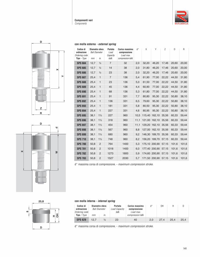
141
Componenti variComponents
Codice di Diametro sfera Portata Carico massimo d* X Y Z D Rordinazione Ball Diameter Load compressione
Ordering code Capacity Load max.Tipo - Type mm in. daN compression daN
12,7 ½ 7 32 2,0 32,20 46,20 17,46 20,60 20,00
12,7 ½ 14 38 2,0 31,80 46,20 17,46 20,60 20,00
12,7 ½ 23 38 2,0 32,20 46,20 17,46 20,60 20,00
25,4 1 7 136 5,4 61,90 77,00 22,22 44,50 31,80
25,4 1 23 136 5,0 61,50 77,00 22,22 44,50 31,80
25,4 1 45 136 4,4 60,90 77,00 22,22 44,50 31,80
25,4 1 68 136 5,3 61,80 77,00 22,22 44,50 31,80
25,4 1 91 331 7,7 80,80 95,30 22,22 50,80 38,10
25,4 1 136 331 6,5 79,60 95,30 22,22 50,80 38,10
25,4 1 181 331 5,8 80,50 95,30 22,22 50,80 38,10
25,4 1 227 331 4,6 80,95 95,30 22,22 50,80 38,10
38,1 1½ 227 960 10,5 115,40 162,10 35,56 60,33 59,44
38,1 1½ 318 960 11,1 121,00 162,10 35,56 60,33 59,44
38,1 1½ 454 960 11,1 129,20 162,10 35,56 60,33 59,44
38,1 1½ 567 960 8,8 127,00 162,10 35,56 60,33 59,44
38,1 1½ 680 960 9,2 146,30 189,70 35,56 60,33 59,44
38,1 1½ 748 960 8,2 156,20 189,70 57,15 60,33 59,44
50,8 2 764 1400 5,3 175,10 200,90 57,15 101,6 101,6
50,8 2 1018 1400 6,0 177,40 200,90 57,15 101,6 101,6
50,8 2 1273 1800 5,9 174,60 200,90 57,15 101,6 101,6
50,8 2 1527 2030 5,7 171,50 200,90 57,15 101,6 101,6
Codice di Diametro sfera Portata Carico massimo d* OH H Dordinazione Ball Diameter Load Capacity compressione
Ordering code daN Load max.Tipo / Type mm in. compression daN
SPS 629 12,7 ½ 23 40 2,0 27,4 25,4 25,4
d* massima corsa di compressione. - maximum compression stroke.
d* massima corsa di compressione. - maximum compression stroke.
con molla esterna - external spring
con molla interna - internal spring
SPS 684
SPS 685
SPS 686
SPS 687
SPS 688
SPS 689
SPS 690
SPS 691
SPS 692
SPS 693
SPS 694
SPS 695
SPS 696
SPS 697
SPS 698
SPS 699
SPS 710
SPS 780
SPS 781
SPS 782
SPS 783

142
1 Regolatori di velocitàSpeed controllers
I rulli regolatori di velocità sono l’ideale solu zio -ne per il problema dello scorrimento su traspor -tatori a gravità, regolando l’avanzamento a velo -cità costante dei colli con carichi da 80 a 1400daN secondo i modelli. Sono indispensabili neltrasporto di colli con materiale delicato o concarichi pesanti per percorsi lunghi. Nonnecessitano di tarature o regolazioni successiveall’installazione, né di manutenzione perchésono lubrificati permanen temente.Il funzionamento è originato dall’energia cineticadegli stessi colli che obbligano delle ganasceinterne, poste al termine di un sistema planeta -rio, ad espandersi per forza centrifuga, svilup -pando così un’azione frenante proporzio nale allavelocità e variabile col carico.É sempre garantita la partenza da fermo dei collie il loro scorrimento risulta regolare anche con ivalori massimi di pendenza.Si consiglia il posizionamento con interasseuguale alla lunghezza dei colli, con carichisuperiori a 800 daN, mentre è possibile uguale a1,5 volte o più per carichi inferiori in funzionedella natura, le dimensioni, ecc. verificandocomunque che i colli non acquistino velocitàsuperiore a 0,3 m/s.L’applicazione ideale è per corsie con trasporto agravità dei pallets, su scaffalature nei magazzinidinamici, con temperatura ambiente da -5°C a 50°C.É consentito l’impiego anche fino a -20°C macon conseguente riduzione dei carichi ammessi.Possono essere considerati valori di temperaturainferiori su richiesta.
The speed controller rollers are the idealsolution for the gravity conveyor systems,regulating the packages with loads ranging from80 to 1400 daN at a constant speed. They areabsolutely necessary for delicate or heavypackages on long conveyors. They do not needto be calibrated or adjusted after installation andas they are permanently lubricated they aremaintenance free.The functioning is originated by the kineticsenergy of the packages that operate internalbrakes, situated ath the end of a crown wheelsystem, to expand by centrifugal force, thusdeveloping a braking force which is proportionalto the speed and variable with the load.Standing start of the packages is alwaysguaranteed and their movement is alwaysregular even with maximum slope values.Assembly with speed controller rollers pitchequal to the load length is recommended forloads heavier than 800 daN, while pitch equal to1.5 times or more for lighter loads do notexceed of 0.3 m/sec., is acceptable.The ideal application is in pallet handling gravitytrack systems and for flow-storage stores withina temperature range of – 5°C to + 50°C.Applications, with consequent reduction of the loadcapacity, are allowed for temperature up to - 20°C.Lower temperature values can be considered onrequest.

143
Componenti variComponents
Serie RV 400In materia plastica ad alta resistenza, ha il corpoesterno rivestito di gomma sintetica antiabrasivacon un particolare accoppiamento,Il telaio di sostegno è in acciaio zincato.I gruppi di sospensione sono forniti in setcompleti, costituiti da perni di fissaggio, molle etiranti, nei quantitativi necessari per ogni singoloregolatore di velocità.
Series RV 400Made of highly resistant plastic material, theexternal body is legged with anti-abrasive syntheticrubber of a toothed design. The supporting frameis of zinc-plated steel.The suspension groups are supplied in completesets, composed by fixing pins, springs andtension rods in the needed quantity for eachsingle speed controller.
RV 402
RV 4J2
RV 403
RV 4J3
TipoType
1,56
0,50
1,56
0,50
PesoWeight
regolatore di velocità - speed controller
gruppo sospensione - suspension group
regolatore di velocità - speed controller
gruppo sospensione - suspension group
DescrizioneDescription
per carico - for load
<500 daN
per carico - for load
500÷1000 daN
NoteNotes

144
1 Regolatori di velocitàSpeed controllers
Serie RV 490Questi regolatori si differenziano nell’applicazione,perché si presentano come rulli portanti conte -nen ti all’interno l’unità che controlla il rotola men -to, quindi vengono montati molto semplicementein sostituzione di un rullo normale.Sono previsti per carichi unitari da 80 daN fino a1400 daN e vengono forniti zincati, completi disupporti e bulloneria di fissaggio. Verificare che icolli non acquis tino velocità superiore a 0,3 m/s.
Series RV 490These controllers differ for the application asthey appear as carrying rollers but with thespeed controlling unit inside; they are easilyassembled instead of a normal roller.They are proposed for unit loads from 80 daN upto 1400 daN all in the zinc-plated executionincluding brackets and mounting materials.Please verify that the unit load doesn't exceed aspeed of 0,3 m/s.
Le piastre di supporto hanno forature asim -metriche.- da montare come indicato qui sopra per rulli
folli Ø 60- da montare ribaltate per rulli folli Ø 50
The brackets plates get asymmetric holes:- to be assembled as shown above for idle
rollers Ø60- to be assembled upside down for idle
rollers Ø50
* Nel codice di ordinazione indicare il valore della lunghezza C in mm, considerando EL=C+39.In the ordering code specify the C length in mm, considering EL=C+39.
ø 80
RV/ES 490
TipoType
C= *
LunghezzaLength
2,764
Peso / Weight daN
C=200 al cm
0,039 80÷1400 145
Peso dei colliUnit weight
daN
LunghezzaLengthC min.
con supportiwith brackets
NoteNotes

145
Componenti variComponents

146
1 ProfiliProfiles
PROFILI PER TRASPORTATORI A GRAVITÀ
Tutti in lamiera zincata a caldo (sendzimir), questiprofili sono previsti prevalentemente per l’impiegonei trasportatori a rulli con asse a molla o foratoe filettato.I tipi PR U50 sono ideali per trasportatori a piùcorsie o per guide di contenimento a rulli.
Tutti i profili sono da intestare per ottenere ilprimo foro con centro a 13 mm dall’estremità;pertanto i valori di lunghezza “L” sono puramentenominali.
PROFILES FOR GRAVITY CONVEYORS
All hot zinc-plated (sendzimir), these profiles aregenerally employed in spring-loaded orinternally threaded shaft idler roller conveyorapplications.The PR U50 type are ideal for conveyor systemswith multiple rows or as roller side frames.
All the profiles are cut to obtain the first holewith a 13 mm pitch from the end, consequently“L” length values are merely nominal.
Profilo-ProfilePR L60 3100 Peso-Weight = 4,60 daN
Profilo-ProfilePR L70 5200Peso-Weight = 14,80 daN
Profilo-ProfilePR U50 6075Peso-Weight = 19,80 daN
Profilo-ProfilePR C70 6000Peso-Weight = 9,70 daN

147
Componenti variComponents
Profilo-ProfilePR C72 5200Peso-Weight = 11,60 daN
Profilo-ProfilePR C73 5200 s=3 Peso-Weight = 15,20 daNPR C74 5200 s=4 Peso-Weight = 20,30 daN
C74
C73
C72
C70
U50
L70
L60
CAPACITÀ DI CARICO Nel diagramma rappresentato si possono rilevarei valori di carico ammissibili dei profili presentati.Tali valori sono variabili in relazione alla distanza“L” fra gli appoggi, validi per un’inflessione mas -sima di f=2 mm., avendo considerato la solleci -tazione e fatica.
LOAD CAPACITYIn the diagram, we show the admissible loadcapacity values of our profiles.Such values are variable in relation to the “L”distance between the supports, valid for a max.inflection of f=2 mm, considering the fatiguestress.

148
1 ProfiliProfiles
PROFILI PER TRASPORTATORI COMANDATI
I profili tipo CP1 e CP2 possono essere fornitigrezzi o con zincatura elettrolitica. Inabbinamento con i profili P5 e P6 carter in PVCgrigio e i tappi di chiusura in Polietilene nero.Sono particolarmente adatti per realizzaretrasportatori a rulli comandati e frizionati delleserie 135 e 138, con catena tangenziale oppurecon trasmissione a cinghie.Tutti i profili sono da intestare per ottenere ilprimo foro con centro a 13 mm dall’estremità;pertanto i valori di lunghezza “L” sono puramentenominali.
PROFILES FOR DRIVEN CONVEYORS
The CP1 and CP2 profiles can be supplied in arough or in a galvanised version. Combined withthe P5 and P6 profiles, grey PVC cover strip andblack Polyethylene end caps. They areparticularly suited to build conveyors withmotorized and friction rollers series 135 and138, with tangential chain or belt transmission.All the profiles are cut to obtain the first holewith a 13 mm pitch from the end, consequently“L” length values are merely nominal.
Profilo-ProfilePR CP1 3000 (Grezzo-Rough)PR CP1J 3000 (Zincato-Galvanized)Peso-Weight = 9,50 daN
Tappo-End cap KR32Code RMSP-00138Peso-Weight = 0,012 daN
Carter-Cover strip L3000PR P5 3000Peso-Weight = 0,75 daN
Profilo-ProfilePR CP2 3000 (Grezzo-Rough)PR CP2J 3000 (Zincato-Galvanized)Peso-Weight = 11,00 daN
Tappo-End cap KR31Code RMSP-00137Peso-Weight = 0,017 daN
Carter - cover strip L3000PR P6 3000Peso-Weight = 0,75 daN

149
Componenti variComponents
PORTATA DEI PROFILIValori validi per inflessione max. f=2mm
LOAD CAPACITY OF PROFILESvalid values for a max. inflection f = 2 mm
PROFILO CP2PROFILE CP2
CARTER PVC P6PVC COVER STRIP P6
PROFILO GUIDACATENACHAIN GUIDE PROFILE
CARTER PVC P5PVC COVER STRIP P5
PROFILO CP1PROFILE CP1
ESEMPIO DI APPLICAZIONE CONTRASMISSIONE A CATENAAPPLICATION EXAMPLE WITH CHAINTRANSMISSION
Codice profilo guidacatena Pignone H PesoChain guide profile code Sprocket Weight
daN
RMSP-00135 1/2’ Z=14 27 1,52
RMSP-00136 1/2’ Z=11 33 1,70
RMSP-00134 1/2’ Z=9 37 1,90
Profilo guidacatena - Lunghezza L=2000Chain guide profile - Length L=2000

150
1 ProfiliProfiles
SUPPORTI
Sono elementi di sostegno dei rulli sia folli checomandati, da saldare o imbullonare alle spalledella struttura portante.I tipi della serie 700 possono essere saldati,mentre il fissaggio con viti consente di correg -gere errori di parallelismo e ortogonalità.
SUPPORTS
Supporting elements for gravity and drivenrollers to be welded or bolted to the supportingstructure frames.The series 700 types can be welded, while boltfixing allows correction of any eventual parallelismand squareness mistakes.
Tipo d r Peso/WeightType daN
SPT/3 281 F8 8,5 4 0,032
SPT/3 281 F10 10,5 5 0,030
SPT/3 281 F12 12,5 6 0,028
Tipo d H r Peso/WeightType daN
SPT 500 F10 10,5 34 6 0,050
SPT 500 F12 12,5 32,5 7,5 0,051
SPT 500 F14 14,5 30 10 0,049
SPT 500 F17 17,5 30 10 0,047
Tipo ch H r Peso/WeightType daN
SPT 700 F14 14,5 62,5 10 0,141
SPT 700 F17 17,5 62,5 10 0,136
SPT 700 F18 18,5 60 12,5 0,135
SPT 700 F22 22,5 57,5 15 0,130
Tipo ch r Peso/WeightType daN
SPT 218 F8 8,5 4 0,047
SPT 218 F10 10,5 5 0,045
SPT 218 F12 12,5 6 0,042

151
2
Rulli per trasportatoricon comando a catena
Rollers for chain driven conveyors
Rulli comandati con pignone P1C - P2CPinion sprocket driven rollers P1C - P2C
Rulli comandati con corone 1C - 2CCrown sprocket driven rollers 1C - 2C
Serie 135: rulli comandati 135 series: driven rollers
Rulli con ruota liberaFree wheel rollers
Serie 138: rulli frizionati 138 series: friction rollers
Serie FDN-FDR: rulli frizionatiFDN-FDR series: friction rollers
152
158
164
174
178
186
Serie 139139 series
170

152
Rulli comandati con pignone P1C - P2CPinion sprocket driven rollers P1C - P2C
2
RULLI COMANDATI CON PIGNONEP1C - P2C
Questi rulli sono comandati dalla catena attraversoil pignone con una o due corone saldato in testa altubo, avente il diametro primitivo minore deldiametro rullo. L’ingombro della motorizzazione ènormalmente inferiore al piano dei rulli, ma purrisultando per questo più funzionale, ne consegueun rapporto di trasmissione che penalizza la capa -cità di tiro della catena.I sistemi standard di trasmissione previsti sono:- con catena tangenziale semplice - versione P1C- con anelli di catena - versione P2C
A richiesta i rulli possono essere forniti per tras -missione tangenziale con catena doppia nelle ver -sio ni P1D con 1 corona sfalsata tra un rullo el’altro e P2D con 2 corone per impegno completodella catena doppia.Per le applicazioni e il calcolo della trasmissionerimandiamo al capitolo d'introduzione da pagina 32dedicato alle indicazioni di impiego, mentre per lecaratteristiche costruttive si in tendono le stesse delrullo base corrispondente presentato nel capitolo 1.
Esempi di codice di ordinazioneMPS/Q1 15R 76N 800 P1CPS/S2 25R 133N 1200 P2C
Tutte le quote sono espresse in mm.
PINION SPROCKET DRIVEN ROLLERSP1C - P2C
These rollers are driven by a chain through apinion with one or two sprockets welded at theroller end, having the pitch diameter smaller thanthe roller diameter. The drive clearance is normallylower than the roller plane, but although morefunctional, the transmission ratio compromisesthe chain pull capacity.The standard transmission systems are:- with simple tangential chain - version P1C- with chain loops - version P2C
On request the rollers can be supplied, fortangential chain transmission, with double chainin the P1D version with one sprocket in offsetposition between one roller and the other andwith P2D with 2 sprockets for complete couplingwith the double chain.For the application indications and thetransmission calculation, you can refer to theintroduction chapter from page 32, while thedesign characteristics are the same as for thebase rollers shown in chapter 1.
Ordering code examplesMPS/Q1 15R 76N 800 P1CPS/S2 25R 133N 1200 P2C
All dimensions are in mm.
P1C
P2C
Trasmissione con catena tangenziale sempliceTransmission with tangential chain
Trasmissione con anelli di catenaTransmission with chain loops
P1D
P2D
P1D = a richiesta - con una corona sfalsataper catena tangenziale doppia.P1D = on request - with one sprocket in offsetposition for double tangential chain.
P2D = a richiesta - con 2 corone per catenatangenziale doppia.P2D = on request - with 2 sprockets fordouble tangential chain.

153
Rulli per trasportatori con comando a catenaRollers for chain driven conveyors
Per catena tangenziale sempliceFor simple tangential chain
MPS/Q1
MPS/Q1
MPS/Q2
MPS/Q1
MPS/Q3
PS/Q1
PS/QA
PS/QB
PS/QC
PS/QD
PS/Q1
PS/Q2
PS/Q4
PS/Q4
60
76
76
89
89
89
89
89
89
89
102
133
133
159
61,9
61,9
68,2
74
88,3
74
78,2
83,2
88,3
87,8
83,2
111,90
111,90
141,8
42
42
43
54
60
54
53
59
60
58
58
84
84
105
1,516
1,778
1,778
1,983
1,983
2,358
2,358
2,358
2,358
2,358
2,747
4,615
5,917
7,926
0,056
0,067
0,067
0,077
0,077
0,089
0,089
0,089
0,089
0,089
0,097
0,166
0,183
0,227
1,168
1,424
1,424
1,631
1,631
1,807
1,807
1,807
1,807
1,807
2,183
3,829
4,705
6,716
0,042
0,054
0,054
0,064
0,064
0,064
0,064
0,064
0,064
0,064
0,073
0,127
0,127
0,127
Tipo / Typed(ø) esec. D(ø) esec.
Tubo/Tube Esec. AsseShaft Exec.
Esec. TuboTube Exec.
Lungh./Length Cmin. max.
De Dm
29
29
25
29
32
34
34
34
32
27
34
36
36
40
l1 fs C=200daN
Rullo BaseBasic Roller al cm
daN
Peso / WeightCodice di ordinazione / Ordering codes Opzioni / OptionsAsse/Shaft
68,88
68,88
76,07
80,92
96,1
80,92
86,07
91,09
96,1
95,72
91,09
119,80
119,80
151,28
Dc
15
20
25
30
R
R
R
R
N
N
N
N
200
200
200
200
3
3
4
4
4,5
20
20
25
30
8
13
16
16
B
F
F
F
J-P
J-P
J
J
10x18
12x20
16x25
16x25
MPS/1
PS/20
PS/25
PS/30
2200
2400
2600
3000
2800
3000
d1 M
7,5
7,5
4,4
7,5
12,4
7,5
11,6
8,5
12,4
5,4
8,5
9,4
9,4
13,9
a
7
7
8,8
7
8,8
7
8,8
8,8
8,8
10,8
8,8
10,8
10,8
15,8
m
Legenda delle sigle di esecuzioneR = asse forato e filettatoF = asse con chiave ch fresatoB = asse con chiave ch con bussola metallica
N = tubo in acciaio normaleJ = tubo con zincatura elettroliticaP = rivestimento con guaina morbida in PVC
Execution codes captionR = drilled and threaded shaftF = shaft with slots chB = shaft with slots with metallic bush
N = normal steel tubeJ = zinc-plated tubeP = soft PVC lagging
57,07
57,07
61,34
69,11
81,37
69,11
71,34
76,36
81,37
79,59
76,36
103,67
103,67
130,2
Dp
14
14
12
17
16
17
14
15
16
13
15
17
17
16
Z
1/2”
1/2”
5/8”
1/2”
5/8”
1/2”
5/8”
5/8”
5/8”
3/4”
5/8”
3/4”
3/4”
1”
p
Peso parti rotantiRotating parts weightC=200
daNal cmdaN
Rulli con pignone P1C per catena tangenziale semplice / Pinion sprocket rollers P1C for simple tangential chain
P1C

154
2 Rulli comandati con pignone P1C - P2CPinion sprocket driven rollers P1C - P2C
Per anelli di catena For chain loops
MPS/S1
MPS/S1
MPS/S1
MPS/S2
PS/S1
PS/SA
PS/SB
PS/SC
PS/SD
PS/S1
PS/S2
PS/SF
PS/S2
PS/SG
PS/S4
PS/SH
PS/S4
PS/S7
15
14
14
17
16
17
14
15
16
13
15
17
15
17
15
17
14
16
16
20
25
30
40
R
60
76
89
89
89
89
89
89
89
102
108
133
133
133
133
159
159
159
1/2”
1/2”
1/2”
5/8”
1/2”
5/8”
5/8”
5/8”
3/4”
5/8”
3/4”
3/4”
3/4”
3/4”
3/4”
1”
1”
1”
R
R
R
R
N
N
N
N
N
200
200
200
200
200
2200 57,07
57,07
69,11
81,37
69,11
71,34
76,36
81,37
79,59
76,36
103,67
91,63
103,67
91,63
103,67
114,15
130,2
130,2
61,9
61,9
74
88,3
74
78,2
83,2
88,3
87,8
83,2
111,9
99,8
111,9
99,8
111,9
125,7
141,8
141,8
68,88
68,88
80,92
96,1
80,92
86,07
91,09
96,1
95,72
91,09
119,8
107,76
119,80
107,76
119,80
135,23
151,28
151,28
42
42
54
60
54
55
58
60
58
58
84
70
84
70
84
84
105
105
7,5
7,5
7,5
11,6
7,5
11,6
8,4
11,6
5,4
8,4
9,4
5,4
9,4
5,4
9,4
7,9
13,9
13,9
22
22
22
24
28
24
24
24
40
24
33
33
33
33
33
63,8
48
48
7
7
7
8,8
7
8,8
8,8
8,8
10,8
8,8
10,8
10,8
10,8
10,8
10,8
15,8
15,8
15,8
3
44
44
44
56
8 MPS/1
PS/20
PS/25
PS/30
PS/40
1,516
1,778
1,983
1,983
2,358
2,358
2,358
2,358
2,358
2,747
4,442
4,615
4,615
5,917
5,917
7,926
7,926
8,950
0,056
0,067
0,077
0,077
0,089
0,089
0,089
0,089
0,089
0,098
0,129
0,166
0,166
0,183
0,183
0,227
0,227
0,380
1,168
1,424
1,631
1,631
1,807
1,807
1,807
1,807
1,807
2,183
3,574
3,829
3,829
4,705
4,705
6,716
6,716
7,720
0,042
0,054
0,064
0,064
0,064
0,064
0,064
0,064
0,064
0,073
0,091
0,127
0,127
0,127
0,127
0,171
0,171
0,324
B
F
F
F
F
J-P
J-P
J-P
J
J
J
13
16
16
16
50
56
52
56
67
52
64
60
64
60
64
101
88
20 10X18
12X20
16X25
16X25
16X25
20
25
30
40
3
3,5
4
4
4,5
6
2800
2400
2600
2800
3000
3000
3000
Tipo/Typed(ø) esec. D(ø) esec.
Tubo/Tube Esec. AsseShaft Exec.
Esec. TuboTube Exec.
Lungh./Length Cmin. max.
De Dm m l2 fs C=200daN
Rullo BaseBasicRoller
al cmdaN
Peso / WeightCodice di ordinazione / Ordering codes Opzioni / OptionsAsse/Shaft Dc d1 M a b
Legenda delle sigle di esecuzioneR = asse forato e filettatoF = asse con chiave ch fresatoB = asse con chiave ch con bussola metallica
N = tubo in acciaio normaleJ = tubo con zincatura elettroliticaP = rivestimento guaina morbida in PVC
Execution codes captionR = drilled and threaded shaftF = shaft with slots chB = shaft with slots with metallic bush
N = normal steel tubeJ = zinc-plated tubeP = soft PVC lagging
DpZp
Peso parti rotantiRotating parts weightC=200
daNal cmdaN
88
Rulli con pignone P2C per anelli a catena / Pinion sprocket rollers for chain loops
P2C

155
Rulli per trasportatori con comando a catenaRollers for chain driven conveyors
Exec. B Exec. F
Exec. F 17
d
ch
e
g
20
14
4
g
25
18
4
12
30
22
4
12
40
32
4
12
20
17
4
9
25
17
4
12
Exec. F F17
d
ch
e
g
20
14
4
9
25
18
4
12
30
22
4
12
40
32
4
12
20
17
4
9
25
17
4
12
CAPACITÀ DI CARICO “Pc”
Portata statica: sono indicati i valori di carico alvariare della lunghezza, considerando la flessionedell’asse, la freccia e la sollecitazione del tubo,distinti secondo l’esecuzione dell’asse.
Portata dinamica: sono indicati i valori massimi alvariare della velocità di rotazione, calcolati per unadurata teorica di progetto dei cuscinetti di 10.000 h.
La capacità di carico “Pc” del rullo risulteràessere il valore minore ricavato dalle duetabelle, considerando sempre: Pc ≥ Pdove P è il carico effettivo sul rullo.
LOAD CAPACITY “Pc”
Static load capacity: the different load capacity valuesin relation to the length are indicated considering theshaft deflection, the tube deflection and the stress,split according to the shaft execution.
Dynamic load capacity: the maximum values areindicated in relation to the rotating speed calculatedfor a theoretical bearing life of 10,000 hrs.
The roller load capacity “Pc” shall result in beingthe smallest value obtained from the two tables,always considering that: Pc ≥ P where P is the real load on the roller.
Tipo / Typed(ø) esec. D(ø)
Tubo/Tube Rullo baseBase roller
Asse / Shaft
ESECUZIONI ASSI A RICHIESTA / SHAFT EXECUTION ON REQUEST
MPS/Q1-S1
MPS/Q1-Q2-S1
MPS/Q1-Q3-S1-S2
360
360
360
360
360
380
360
359
360
355
360
360
360
262
360
257
360
256
360
172
360
167
360
165
360
129
360
124
360
122
278
104
360
99
360
97
159
88
335
83
360
81
100
77
210
71
360
70
71
69
149
63
325
61
56
55
117
56
256
54
45
45
95
51
207
49
37
37
78
47
170
45
≤ 200 300 400 600 800 1000 1200 1400 1600 1800 2000 2200
60
60
76
76
89
89
MPS/1
MPS/1
MPS/1
MPS/1
MPS/1
MPS/1
15
15
15
15
15
15
R
B
R
B
R
B
Portata statica / Static load capacity
daN
Lungh. / Length " C"
Valori di portata riferiti all’esecuzione asse standard con fori filettati per fissaggio con viti su struttura rigida.The load capacity values refer to the standard threaded execution for screw fixing on rigid structure.
Esecuzioni assi a richiesta / Shaft execution on request
Nota:Il carico P effettivo sul rullo si intende unifor -memente distribuito. Nel caso di carico con -centrato o insistente principalmente su una solatestata del rullo, i valori di portata indicati nelletabelle vanno dimezzati.
Note:The real load P is intended as uniformlydistributed on the roller. In case ofconcentrated load or load mainly resting on oneroller end, the admitted load capacity values inthe tables are reduced by 50%.

156
2 Rulli comandati con pignone P1C - P2CPinion sprocket driven rollers P1C - P2C
Tipo / Typed(ø) esec. D(ø)
Tubo/Tube Rullo baseBase roller
Asse / Shaft
PS/Q4-S4-SG
PS/Q4-S4-SH
1300
1300
1300
1300
1300
1300
1300
1300
1300
1102
1300
1068
1300
921
1300
887
1300
795
1300
760
1300
702
1300
666
1182
630
1300
593
952
574
1300
536
784
528
1300
490
656
490
1268
451
516
445
997
404
417
407
805
367
≤ 600 800 1000 1200 1400 1600 1800 2000 2200 2400 2700 3000
133
133
159
159
PS/30
PS/30
PS/30
PS/30
30
30
30
30
R
F
R
F
Portata statica / Static load capacity
daN
Lungh. / Length " C"
Tipo / Typed(ø) esec. D(ø)
Tubo/Tube Rullo baseBase roller
Asse / Shaft
PS/S72200
2200
2200
2200
2200
2049
2200
1765
2200
1557
2200
1398
1841
1273
1515
1172
1268
1090
1077
1021
926
902
805
786
≤ 800 1000 1200 1400 1600 1800 2000 2200 2400 2600 2800 3000
159
159
PS/40
PS/40
40
40
R
F
daN
Lungh. / Length " C"
Valori di portata riferiti all’esecuzione asse standard con fori filettati per fissaggio con viti su struttura rigida.The load capacity values refer to the standard threaded execution for screw fixing on rigid structure.
Portata statica / Static load capacity
ESECUZIONI ASSI A RICHIESTA / SHAFT EXECUTION ON REQUESTPortata statica / Static load capacity
Tipo / Typed(ø) esec. D(ø)
Tubo/Tube Rullo baseBase roller
Asse / Shaft
PS/S2
PS/Q2-S2-SF
800
800
800
800
800
800
800
800
800
667
800
648
800
533
800
514
800
446
800
426
800
385
800
365
701
340
800
320
550
305
800
285
443
278
800
257
365
256
784
235
259
223
557
201
194
189
417
176
≤ 400 600 800 1000 1200 1400 1600 1800 2000 2200 2600 3000
108
108
133
133
PS/25
PS/25
PS/25
PS/25
25
25
25
25
R
F
R
F
daN
Lungh. / Length " C"
ESECUZIONI ASSI A RICHIESTA / SHAFT EXECUTION ON REQUESTPortata statica / Static load capacity
Tipo / Typed(ø) esec. D(ø)
Tubo/Tube Rullo baseBase roller
Asse / Shaft
PS/Q1-QA-QB-QC-QD-
S1-SA-SB-SC-SD
PS/Q1-S1
550
600
550
600
550
448
550
444
550
312
550
307
550
240
550
236
550
196
550
192
550
167
550
162
378
145
550
141
292
129
446
125
210
112
320
107
145
95
221
90
123
89
188
84
161
78
≤ 300 500 700 900 1100 1300 1500 1700 2000 2400 2600 2800
89
89
102
102
PS/20
PS/20
PS/20
PS/20
20
20
20
20
R
F
R
F
daN
Lungh. / Length " C"

157
Rulli per trasportatori con comando a catenaRollers for chain driven conveyors
Rullo base / Base Roller 10 25 50 75 100 150 200 250 300 400 500
MPS/1 360 294 234 204 185 162 147 137 129 117 108
PS/20 600 596 473 413 375 328 298 277 260 237 220
PS/25 800 744 591 516 469 410 372 346 325 295 274
PS/30 1300 1034 821 717 651 569 517 480 452 410 381
PS/40 2200 2171 1723 1506 1368 1195 1086 1008 948 862 800
Portata dinamica / Dynamic load capacity
VELOCITÀ DI ROTAZIONE
Per comodità abbiamo indicato la portata dinamicadei rulli al variare della velocità di rotazione (velo -cità angolare) espressa in giri al minuto.
La tabella successiva riporta la trasformazione travelocità periferica in m/s e m/min in numero digir/min per i vari diametri di rullo.
ROTATING SPEED
For convenience we indicated the roller load capacityin relation to the variation of the rotating speed(angular speed) expressed in rev/min.
The following table indicates the transformation of theperipheral speed in m/s and m/min into a number ofrev/min referred to the different roller diameters.
Velocità periferica - Periphal speed Diametro m/s 0,05 0,1 0,15 0,2 0,3 0,4 0,5 0,6 0,7 0,8 0,9 1 Diameter “D” m/min 3 6 9 12 18 24 30 36 42 48 54 60
60 16 32 48 64 95 127 159
76 13 25 38 50 75 101 126 151 176 201 226 251
89 11 21 32 43 64 86 107 129 150 172 193 215
102 9 19 28 37 56 75 94 112 131 150 169 187
108 9 18 27 35 53 71 88 106 124 141 159 177
133 7 14 22 29 43 57 72 86 101 115 129 144
159 6 12 18 24 36 48 60 72 84 96 108 120
giri/minrev/min
daN
giri/min - rev/min

158
2 Rulli comandati con corone 1C - 2CCrown sprocket driven rollers 1C - 2C
RULLI COMANDATI CON CORONE1C – 2C
Questi rulli sono comandati dalla catena attraversouna o due corone saldate sul tubo, aventi pertantoil diametro primitivo maggiore del diametro delrullo e l’ingombro della motorizzazione superioreal piano dei rulli. Ne consegue un rapporto ditrasmissione migliore, che riduce il tiro sullacatena e le sollecitazioni ai vari organi.I sistemi standard di trasmissione con questaesecuzione sono:- con catena tangenziale semplice – versione 1C- con anelli di catena – versione 2CPer le applicazioni e il calcolo della trasmissionerimandiamo al capitolo d'introduzione da pag. 32dedicato alle indicazioni di impiego, mentre per lecaratteristiche costruttive si intendono le stessedel rullo base presentato nel capitolo 1.
Esempi di codice di ordinazioneGL/K3 12R 50NU 600 1CPS/N1 20R 89ND 1000 2CMPS/K1 15B 76JUP 800 1C
Tutte le quote sono espresse in mm.
CROWN SPROCKET DRIVEN ROLLERS1C – 2C
These rollers are driven by a chain thanks to oneor two crown sprockets welded on the tube, thushaving a pitch diameter bigger than the rollerdiameter.The result is a better transmission ratio reducingthe chain pull and the stress of the variouscomponents.Different transmission systems are possible:- with simple tangential chain – version 1C- with chain loops – version 2CFor the application indications and thetransmission calculation, you can refer to thechapter from page 32 “application indicationsand design criteria”, while the designcharacteristics are the same as for the baserollers shown in chapter 1.
Ordering code exampleGL/K3 12R 50NU 600 1CPS/N1 20R 89ND 1000 2CMPS/K1 15B 76JUP 800 1C
All dimensions are in mm.
1C
2C
Trasmissione con catena tangenziale sempliceTransmission with simple tangential chain
Trasmissione con anelli di catenaTransmission with chain loops

159
Rulli per trasportatori con comando a catenaRollers for chain driven conveyors
GL/K1
GL/K3
GL/K3
GM/K2
GM/K2
GM/K2
MPS/K1
MPS/K1
MPS/K1
MPS/K1
PS/K1
PS/KA
PS/K1
PS/K1
PS/KA
PS/K1
PS/K2
PS/K2
PS/K4
Tipo / Typed(ø) esec. D(ø) esec.
Tubo/Tube Esec. AsseShaft Exec.
Esec. TuboTube Exec.
Lungh./Length Cmin. max.
De fs C=200daN
Rullo BaseBasic Roller
al cmdaN
Peso / WeightCodice di ordinazione / Ordering codes Opzioni / OptionsAsse/Shaft Dc
10
12
12
32
50
60
50
60
76
50
60
76
89
60
76
76
89
89
102
89
108
108
1400
1600
1600
1600
2000
2200
1600
2200
2200
2200
2400
2600
2600
2600
2600
2800
2600
2800
2800
3/8”
1/2”
1/2”
1/2”
1/2”
5/8”
1/2”
1/2”
5/8”
5/8”
3/4”
5/8”
3/4”
5/8”
3/4”
3/4”
3/4”
3/4”
3/4”
15
17
20
17
20
20
17
20
20
23
15
20
17
23
19
21
19
23
23
45,81
69,11
81,19
69,11
81,19
101,49
69,11
81,19
101,49
116,58
91,63
101,49
103,67
116,58
115,75
127,82
115,75
139,9
139,9
49,5
74
86
74
86
108,4
74
86
108,4
123,5
99,8
108,4
111,9
123,5
123,9
136
123,9
148,1
148,1
54,07
80,92
93
80,92
93
116,22
80,92
93
116,22
131,31
107,76
116,22
119,8
131,31
131,88
143,95
131,88
156,03
156,03
1,5
1,5
1,5
1,5
2
2
10
12
12
15
20
20
5
GL/60 0,488
0,892
1,038
0,957
1,277
1,638
1,248
1,697
2,188
2,545
3,028
3,450
3,450
3,613
3,613
4,054
3,739
5,298
6,708
0,018
0,027
0,030
0,032
0,042
0,050
0,047
0,056
0,068
0,078
0,067
0,079
0,079
0,089
0,089
0,089
0,093
0,129
0,146
0,358
0,693
0,839
0,693
0,979
1,340
0,968
1,348
1,838
2,196
2,474
2,899
2,899
3,060
3,060
3,502
2,87
4,427
5,454
0,012
0,018
0,022
0,018
0,029
0,037
0,033
0,042
0,054
0,064
0,042
0,054
0,054
0,064
0,064
0,073
0,064
0,091
0,091
M
M-F
F
B
F
F
F
J-P
J-P
J-P
J-P
J-P
J-P
GL/12
GM/15
MPS/1
PS/20
PS/25
PS/30
8
8
13
16
16
5
7
7
7
7
8,8
7
7
8,8
8,8
10,8
8,8
10,8
8,8
10,8
10,8
10,8
10,8
10,8
9,5
10
13,5
10
13,5
14,5
13,5
13,5
14,5
16,5
12
9,3
12
9,3
12
12
12
12
12
6x10
8x15
8x15
10x18
10x18
12x20
16x25
16x25
3
3
3
3,5
3,5
NU
NU
NU
NU
NU
NU
100
150
150
200
200
200
15
15
20
25
30
R
R
R
R
R
R
d1 M a m
Legenda delle sigle di esecuzioneR = asse forato e filettatoM = asse con estremità filettateF = asse con chiave ch fresatoB = asse con chiave ch con bussola metallica
NU = tubo in acciaio normale e 1 coronaJ = tubo con zincatura elettroliticaP = rivestimento con guaina morbida in PVC
Execution codes captionR = drilled and threaded shaftM = shaft with threaded endsF = shaft with slots chB = shaft with slots with metallic bush
NU = normal steel tube and 1 crownJ = zinc-plated tubeP = soft PVC lagging
DpZp
Peso parti rotantirotating parts weight
C=200daN
al cmdaN
Rulli con corona per catena tangenziale semplice 1C / Crown sprocket rollers for simple tangential chain 1C
25
30
Per catena tangenziale sempliceFor simple tangential chain 1C

160
2 Rulli comandati con corone 1C - 2CCrown sprocket driven rollers 1C - 2C
Per anelli di catenaFor chain loops
GL/N1
GL/N3
GL/N3
GM/N2
GM/N2
GM/N2
MPS/N1
MPS/N1
MPS/N1
MPS/N1
PS/N1
PS/NA
PS/N1
PS/N1
PS/NA
PS/N1
PS/N2
PS/N2
PS/N4
Tipo / Typed(ø) esec. D(ø) esec.
Tubo/Tube Esec. AsseShaft Exec.
Esec. TuboTube Exec.
Lungh./Length Cmin. max.
De fs C=200daN
Rullo BaseBasic Roller
al cmdaN
Peso / WeightCodice di ordinazione / Ordering codes Opzioni / OptionsAsse/Shaft Dc
10
12
12
32
50
60
50
60
76
50
60
76
89
60
76
76
89
89
102
89
108
108
1400
1600
1600
1600
2000
2200
1600
2200
2200
2200
2400
2600
2600
2600
2600
2800
2600
2800
2800
3/8”
1/2”
1/2”
1/2”
1/2”
5/8”
1/2”
1/2”
5/8”
5/8”
3/4”
5/8”
3/4”
5/8”
3/4”
3/4”
3/4”
3/4”
3/4”
15
17
20
17
20
20
17
20
20
23
15
20
17
23
19
21
19
23
23
45,81
69,11
81,19
69,11
81,19
101,49
69,11
81,19
101,49
116,58
91,63
101,49
103,67
116,58
115,75
127,81
115,75
139,9
139,9
49,5
74
86
74
86
108,4
74
86
108,4
123,5
99,8
108,4
111,9
123,5
123,9
136
123,9
148,1
148,1
54,07
80,92
93
80,92
93
116,22
80,92
93
116,22
131,31
107,76
116,22
119,8
131,31
131,88
143,95
131,88
156,03
156,03
1,5
1,5
2
2
5
GL/60 0,488
0,892
1,038
0,957
1,277
1,638
1,248
1,697
2,188
2,545
3,028
3,450
3,450
3,613
3,613
4,054
3,739
5,298
6,708
0,018
0,027
0,030
0,032
0,042
0,050
0,047
0,056
0,068
0,078
0,067
0,079
0,079
0,098
0,089
0,098
0,093
0,129
0,146
0,358
0,693
0,839
0,693
0,979
1,340
0,968
1,348
1,838
2,196
2,474
2,899
2,899
3,060
3,060
3,502
2,87
4,427
5,454
0,012
0,018
0,022
0,018
0,029
0,037
0,033
0,042
0,054
0,064
0,042
0,054
0,054
0,064
0,064
0,073
0,064
0,091
0,091
M
M-F
F
B
F
F
F
J-P
J-P
J-P
J-P
J-P
J-P
GL/12
GM/15
MPS/1
PS/20
PS/25
PS/30
8
8
13
16
16
5
7
7
7
7
8,8
7
7
8,8
8,8
10,8
8,8
10,8
8,8
10,8
10,8
10,8
10,8
10,8
9,5
10
13,5
10
13,5
14,5
13,5
13,5
14,5
16,5
12
9,3
12
9,3
12
12
12
12
12
6x10
8x15
8x15
10x18
10x18
12x20
16x25
16x25
3
3
3
3,5
3,5
ND
ND
ND
ND
ND
ND
100
150
150
200
200
200
15
15
20
25
30
R
R
R
R
R
R
d1 M a
17
21
21
21
21
24
21
21
24
24
33
24
33
24
33
33
33
33
33
b mDpZp
Peso parti rotantirotating parts weight
C=200daN
al cmdaN
Rulli con corone per anelli di catena 2C / Crown sprocket rollers for chain loops
10
12
12
15
20
20
25
30
2C
Legenda delle sigle di esecuzioneR = asse forato e filettatoM = asse con estremità filettateF = asse con chiave ch fresatoB = asse con chiave ch con bussola metallica
ND = tubo in acciaio normale e 2 coroneJ = tubo con zincatura elettroliticaP = rivestimento con guaina morbida in PVC
Execution codes captionR = drilled and threaded shaftM = shaft with threaded endsF = shaft with slots chB = shaft with slots with metallic bush
ND = normal steel tube and 2 crownsJ = zinc-plated tubeP = soft PVC lagging

161
Rulli per trasportatori con comando a catenaRollers for chain driven conveyors
Exec. F 17
d
ch
e
g
20
14
4
9
25
18
4
12
30
22
4
12
20
17
4
9
25
17
4
12
d
ch
e
g
12
10
5
6
15
12
4
9
d
M
e
g
v*
10
10
4
21,5
6,5
12
12
4
27,5
7,5
CAPACITÀ DI CARICO “Pc”
Portata statica: sono indicati i valori di carico alvariare della lunghezza, considerando la flessionedell’asse, la freccia e la sollecitazione del tubo.
Portata dinamica: sono indicati i valori massimi alvariare della velocità di rotazione, calcolati per unadurata di progetto dei cuscinetti di 10.000 h.
La capacità di carico “Pc” del rullo risulteràessere il valore minore ricavato dalle duetabelle, considerando sempre: Pc ≥ Pdove P è il carico effettivo sul rullo.
LOAD CAPACITY “Pc”
Static load capacity: the different load capacity valuesin relation to the length are indicated considering theshaft deflection, the tube deflection and the stress.
Dynamic load capacity: the maximum values areindicated in relation to the rotating speed calculatedfor a theoretical bearing life of 10,000 hrs.
The roller load capacity “Pc” shall result in beingthe smallest value obtained from the two tables,always considering that: Pc ≥ Pwhere P is the real load on the roller.
Tipo / Typed(ø) esec. D(ø)
Tubo/Tube Rullo baseBase roller
Asse/Shaft
GL/K1-N1
GL/K3-N3
120
140
140
140
140
63
140
140
140
140
62
140
140
140
140
41
140
140
140
140
29
115
115
140
140
21
84
84
140
140
16
63
63
110
110
12
48
48
85
85
9
38
38
67
67
8
30
30
53
53
25
25
43
43
22
22
38
38
≤ 500 600 700 800 900 1000 1100 1200 1300 1400 1500 1600
32
50
50
60
60
GL/60
GL/12
GL/12
GL/12
GL/12
10
12
12
12
12
R
R
F
R
F
Portata statica / Static load capacity
daN
Lungh. / Length " C"
(*) valori previsti per dadi bassi UNI 5589expected values for short nuts UNI 5589
GL / Exec. M MPS / Exec. B PS / Exec. FGL-GM / Exec. F
Esecuzioni assi a richiesta / Shaft execution on request
Valori di portata riferiti all’esecuzione asse standard con fori filettati per fissaggio con viti su struttura rigida.The load capacity values refer to the standard threaded execution for screw fixing on rigid structure.
Nota:Il carico P effettivo sul rullo si intende unifor -memente distribuito. Nel caso di carico con -centrato o insistente principalmente su una solatestata del rullo, i valori di portata indicati nelletabelle vanno dimezzati.
Note:The real load P is intended as uniformly distri -buted on the roller. In case of concentrated loador load mainly resting on one roller end, theadmitted load capacity values in the tables arereduced by 50%.

162
2 Rulli comandati con corone 1C - 2CCrown sprocket driven rollers 1C - 2C
Tipo / Typed(ø) esec. D(ø)
Tubo/Tube Rullo baseBase roller
Asse/Shaft
PS/K1-N1
550
600
550
600
550
600
550
600
550
478
550
455
550
448
550
444
550
344
550
319
550
312
550
307
396
275
550
248
550
240
550
236
214
203
448
205
550
196
550
192
128
123
269
175
550
167
550
162
83
80
173
154
378
145
550
141
64
62
134
130
292
129
446
125
46
45
96
94
210
112
320
107
32
31
66
65
145
95
221
90
56
55
123
89
188
84
161
78
≤ 300 500 700 900 1100 1300 1500 1700 2000 2400 2600 2800
60
60
76
76
89
89
102
102
PS/20
PS/20
PS/20
PS/20
PS/20
PS/20
PS/20
PS/20
20
20
20
20
20
20
20
20
R
F
R
F
R
F
R
F
Portata statica / Static load capacity
Portata statica / Static load capacity
daN
Lungh. / Length " C"
Tipo / Typed(ø) esec. D(ø)
Tubo/Tube Rullo baseBase roller
Asse/Shaft
PS/K2-N2
800
800
800
800
800
800
800
800
800
708
800
667
800
575
800
533
760
490
800
446
473
432
800
385
335
320
701
340
263
252
550
305
212
204
443
278
174
169
365
256
124
120
259
223
223
210
≤ 400 600 800 1000 1200 1400 1600 1800 2000 2200 2600 2800
89
89
108
108
PS/25
PS/25
PS/25
PS/25
25
25
25
25
R
F
R
F
daN
Lungh. / Length " C"
Valori di portata riferiti all’esecuzione asse standard con fori filettati per fissaggio con viti su struttura rigida.The load capacity values refer to the standard threaded execution for screw fixing on rigid structure.
Portata statica / Static load capacity
Tipo/Typed(ø) esec. D(ø)
Tubo/Tube Rullo baseBase roller
Asse/Shaft
MPS/K1-N1
360
360
360
360
360
360
360
360
360
360
360
359
360
355
360
353
360
269
360
262
360
257
360
256
360
180
360
172
360
167
360
165
308
137
360
129
360
124
360
122
156
113
278
104
360
99
360
97
90
88
159
88
335
83
360
81
56
55
100
77
210
71
360
70
40
39
71
69
149
63
325
61
56
55
117
56
256
54
45
45
95
51
207
49
37
37
78
47
170
45
≤ 200 300 400 600 800 1000 1200 1400 1600 1800 2000 2200
50
50
60
60
76
76
89
89
MPS/1
MPS/1
MPS/1
MPS/1
MPS/1
MPS/1
MPS/1
MPS/1
15
15
15
15
15
15
15
15
R
B
R
B
R
B
R
B
daN
Lungh. / Length " C"
Portata statica / Static load capacity
Tipo / Typed(ø) esec. D(ø)
Tubo/Tube Rullo baseBase roller
Asse/Shaft
GM/K2-N2
200
200
220
220
240
207
169
164
220
198
240
182
118
115
220
179
240
162
85
83
195
165
240
147
64
62
146
143
240
135
49
48
112
110
232
125
38
38
88
86
182
116
31
30
70
69
145
109
22
22
50
49
103
97
39
39
81
80
32
31
66
65
54
54
≤ 700 800 900 1000 1100 1200 1300 1400 1600 1800 2000 2200
50
50
60
60
76
76
GM/15
GM/15
GM/15
GM/15
GM/15
GM/15
15
15
15
15
15
15
R
F
R
F
R
F
daN
Lungh. / Length " C"

163
Rulli per trasportatori con comando a catenaRollers for chain driven conveyors
Portata statica / Static load capacity
Tipo/Typed(ø) esec. D(ø)
Tubo/Tube Rullo baseBase roller
Asse/Shaft
PS/K4-N41000
1000
1000
1000
1000
1000
1000
1000
989
894
701
670
550
528
443
427
365
353
305
296
259
252
223
217
≤ 600 800 1000 1200 1400 1600 1800 2000 2200 2400 2600 2800
108
108
PS/30
PS/30
30
30
R
F
daN
Lungh. / Length " C"
Portata dinamica / Dynamic load capacity giri/min - rev/min Rullo base/Base roller 10 25 50 75 100 150 200 250 300
GL/60 120 76 54 44 38 31 27 24 22
GL/12 122 77 55 45 39 32 27 24 22
GM/15 240 200 193 169 153 134 122 113 106
MPS/1 360 294 234 204 185 162 147 137 129
PS/20 600 596 473 413 375 328 298 277 260
PS/25 800 744 591 516 469 410 372 346 325
PS/30 1000 934 821 717 651 569 517 480 452
daN
VELOCITÀ DI ROTAZIONE
Per comodità abbiamo indicato la portata dinamicadei rulli al variare della velocità di rotazione (velo -cità angolare) espressa in giri al minuto.
La tabella successiva riporta la trasformazione travelocità periferica in m/s e m/min in numero digiri/min per i vari diametri di rullo.
ROTATING SPEED
For convenience we indicated the roller load capacityin relation to the variation of the rotating speed(angular speed) expressed in rev/min.
The following table indicates the transformation of theperipheral speed in m/s and m/min into a number ofrev/min referred to the different roller diameters.
Velocità periferica - Periphal speed Diametro m/s 0,05 0,1 0,15 0,2 0,3 0,4 0,5 0,6 0,7 0,8 0,9 1 Diameter “D” m/min 3 6 9 12 18 24 30 36 42 48 54 60
32 30 60 90 119 179 239 298
50 19 38 57 76 115 153 191 229 267 306 344 382
60 16 32 48 64 95 127 159 191 223 255 286 318
76 13 25 38 50 75 101 126 151 176 201 226 251
89 11 21 32 43 64 86 107 129 150 172 193 215
102 9 19 28 37 56 75 94 112 131 150 169 187
108 9 18 27 35 53 71 88 106 124 141 159 177
giri/minrev/min
Valori di portata riferiti all’esecuzione asse standard con fori filettati per fissaggio con viti su struttura rigida.The load capacity values refer to the standard threaded execution for screw fixing on rigid structure.

164
SerieSeries 1352
RULLI COMANDATI CON PIGNONE P1C – P2CQuesti rulli hanno caratteristiche generalicorrispondenti a quelle della serie 117 e sonoperfettamente intercambiabili con quelli fri -zionati della serie 138.Insieme queste serie consentono di ottenere lepiù svariate combinazioni, con la massimaflessibilità di trasporto e modularità dell’impianto.I pignoni sono in Poliammide di colore nero,opportunamente stabilizzati e particolarmenteresistenti all’usura e alla fatica, bloccati con unparticolare sistema ad innesto nell’elementointerposto all’estremità del tubo, oppure in ac -cia io saldati all’estremità del tubo o ad innestosu richiesta. I tipi con pignone in Poliammidesono previsti in esecuzione con tubo in acciaiozincato sendzimir (esec. Z), esclusi i tipi135/Q4-S4, oppure in speciale PVC antiurtofonoassorbente (esec. V).I tipi con pignone in acciaio sono invece previsticon tubo in acciaio normale. I pignoni in Poli -am mide possono essere facilmente sostituiticon quelli della serie 138, modificando senzaproblemi trasportatori comandati in corsie diaccumulo; inoltre combinati con tubo in PVC oin acciaio inox AISI 304 trovano ottima appli -cazione negli ambienti alimentari, corrosivi econ sgoc ciolamenti. L’impiego è normalmenteconsentito per temperature ambiente da –5° C a+80° C con tubo in acciaio e da –5° C a +50° Ccon tubo in PVC.La velocità d’avanzamento dei colli può rag -giun gere 0,5 m/s con pignoni Z=9/11 o Z=14 inacciaio e 1 m/s con pignoni Z=14 in Poliam -mide, compatibilmente con i carichi ammessiindicati nella tabella a pag. 168.Questi rulli sono dotati di cuscinetti radiali rigidi6002-2RZ standard o inox a richiesta.I sistemi di trasmissione sono previsti con:- catena tangenziale semplice versione P1C- anelli di catena versione P2C É possibile prevedere rulli con interassi minimidi I=42 mm applicando D.40 con Z=9, oppureI=52 applicando D.50 con Z=9/11. Per altre indicazioni di impiego e il calcolo dellatrasmissione rimandiamo al capitolo “Indicazionidi impiego e criteri di progettazione” da pag 32.
Nell’indicare il codice di ordinazione vannoriportati il tipo, il diametro e l’esecuzione asse, ildiametro e l’esecuzione tubo, la lunghezza “C”.
Esempi di codice di ordinazione135/Q3 14R 50Z 600 (P1C)135/S3 14R 60NP 800 (P2C)
Le notizie sulle materie plastiche impiegate so -no riportate nell’introduzione.Tutte le quote sono espresse in mm.
PINION SPROCKET ROLLERS P1C – P2CThese rollers have the same general characteristicsof the series 117 and are perfectly interchangeablewith the series 138 friction rollers.These series together allow various combinationswith the maximum handling flexibility andsystem modularity.The pinions are in black coloured Polyamideparticularly stabilized, wear and fatigue resistant,assembled with a particular insert system intothe element situated in-between the tube ends orin steel welded to the tube ends, inserted onrequest. The types with Polyamide pinions aresupplied in the sendzimir zinc plated steel tubeexecution (“Z” execution), except the 135/Q4-S4types, or in special anti-shock or noiseless PVC(“V” execution).The types with steel pinion are supplied withnormal steel tube.The Polyamide pinions can be easily changedwith the ones of the series 138, changing withno problems driven rollers systems intoaccumulating sections; furthermore ifcombined with a PVC tube or in stainless steelAISI 304 they find very good applications infoodstuffs, corrosive and wet environments.The application temperatures range from –5° Cto +80° C with steel tube and from –5° C to+50° C with PVC tube. The package handling speed may reach 0,5 m/swith steel pinions Z=9 / 11 or Z=14 and 1 m/swith Polyamide Z=14 pinions, compatibly withthe permitted loads as indicated in the table atpage 168.These rollers are supplied with radial precision6002-2RZ ball bearings or in stainless steel onrequest.The transmission systems are planned with:- simple tangential chain version P1C- chain loops version P2CIt is possible to mount rollers with a min. pitchof I=42 mm assembling D.40 with Z=9 or I=52mm assembling D.50 with Z=9/11.For other application indications andtransmission calculations please refer to thechapter “Application indications and designcriteria” from page 32.
In indicating the ordering code, please specifythe type, the shaft diameter and execution, thetube diameter and execution, the “C” length.
Ordering code examples135/Q3 14R 50Z 600 (P1C)135/S3 14R 60NP 800 (P2C)
The information on the plastic materialsemployed are listed in the introduction section.All dimensions are in mm.

165
Rulli per trasportatori con comando a catenaRollers for chain driven conveyors
P1CCon pignone in Poliammide per catenatangenziale sempliceWith Polyamide pinion sprocket forsimple tangential chain
P2CCon pignone in Poliammide per anellidi catenaWith Polyamide pinion sprocket forchain loops
P1C Z=9/11
P1C Z=14
P2C Z=14

166
SerieSeries 1352
135/Q1
135/Q2
135/Q3
135/Q4
135/Q7
135/Q8
135/Q9
Tipo / Typed(ø) esec. D(ø) esec.
Tubo / Tube Esec. AsseShaft Exec.
Esec. TuboTube Exec.
Lungh. / Length Cmin max
s C=200daN
Rullo BaseBasic Roller
Tubo / Tube
al cmdaN
Peso / WeightCodice di ordinazione / Ordering codes Opzioni / OptionsAsse / Shaft
14
40
50
60
40
50
60
50
60
60
50
63
50
63
50
63
1200
1400
1600
2000
9
11
14
14
9
11
14
1/2”
1/2”
1/2”
1/2” 14 57,072,8
3PVC
37,13
45,08
57,07
57,07
37,13
45,08
57,07
1,2
1,5
1,5
1,2
1,5
1,5
1,5
1,5
3
2,8
3
2,8
3
2,8
3
Acciaio
Steel
PVC
117/14
117/34
0,513
0,688
0,757
0,525
0,700
0,769
0,721
0,791
1,099
0,495
0,560
0,507
0,572
0,550
0,596
0,011
0,030
0,034
0,011
0,030
0,034
0,030
0,034
0,055
0,018
0,021
0,018
0,021
0,018
0,021
0,244
0,419
0,488
0,256
0,431
0,500
0,452
0,522
0,830
0,219
0,291
0,231
0,303
0,281
0,327
0,009
0,018
0,022
0,009
0,018
0,022
0,018
0,022
0,042
0,006
0,008
0,006
0,008
0,006
0,008
J-I
J-I
J-I
J
N-J-I-P
J-P
J-I
J-I
J-I
N-J-I-P
N-J-I-PZ
Z
Z
N
V
V
V
130
130
130
130
130800
1000
800
1000
800
1000
130
130
14
14
14
14
14
R
R
R
R
R
R
14 R
135/S3
135/S4
135/S9
14
14
57,07
57,07
1,5
3
Acciaio
Steel117/14
117/34
0,721
0,791
1,099
0,550
0,596
0,030
0,034
0,055
0,018
0,021
0,452
0,522
0,830
0,281
0,327
0,018
0,022
0,042
0,006
0,008J-I
J-I N-J-I-P
J J-P
Z
N
V
14 R
150
150
150
1600
2000
800
1000
14
14
R
R
DpZp
Peso parti rotantirotating parts weightC=200
daNal cmdaN
Nota:Questi rulli possono essere forniti:- in esecuzione con cuscinetti in acciaio inox AISI 440- in esecuzione antistaticaSono disponibili profili idonei per la realizzazione di spalledi sostegno con catena tangenziale; vedi pag 148-149.
Note:These rollers can be:- supplied with stainless steel bearings AISI 440- in antistatic versionSuitable profiles for tangential chain are available;see pages 148-149.
Rulli con pignone P2C / Pinion sprocket rollers P2C
Rulli con pignone P1C / Pinion sprocket rollers P1C
50
60
60
50
63
Tubo D.63 in PVC su richiestaD.63 tube in PVC is on request
Legenda delle sigle di esecuzioneR = asse forato e filettatoJ = tubo con zincatura elettroliticaI = asse in acciaio inox AISI 304
Z = tubo con zincatura a caldo (sendzimir)V = tubo in PVC rigidoN = tubo in acciaio normaleJ = tubo con zincatura elettroliticaI = tubo in acciaio inox AISI 304P = rivestimento con guaina morbida in PVC
Execution codes captionR = drilled and threaded shaftJ = zinc-plated shaftI = stainless steel shaft AISI 304
Z = hot dip zinc-plated tube (sendzimir)V = rigid PVC tubeN = normal steel tubeJ = zinc-plated tubeI = stainless steel tube AISI 304P = soft PVC lagging
Rulli comandati 135 P1C - P2C con pignone in Poliammide / 135 rollers with single or double sprocket in Polyamide

167
Rulli per trasportatori con comando a catenaRollers for chain driven conveyors
P1CCon pignone in acciaio per catenatangenziale sempliceWith steel pinion sprocket for simpletangential chain
P2CCon pignone in acciaio per anelli di catenaWith steel pinion sprocket for chain loops
P1C Z=14
P2C Z=14
135/Q5
135/Q6
Tipo / Typed(ø) esec. D(ø) esec.
Tubo / Tube Esec. AsseShaft Exec.
Esec. TuboTube Exec.
Lungh. / Length Cmin max
s C=200daN
Rullo BaseBasic Roller
Tubo / Tube
al cmdaN
Peso / WeightCodice di ordinazione / Ordering codes Opzioni / OptionsAsse / Shaft
1450
60
60
1600
160014
14
1/2”
1/2”
57,07
57,07
1,5
1,5
3
Acciaio
Steel117/14
1,053
1,086
1,267
0,030
0,034
0,055
0,851
0,884
1,065
0,018
0,022
0,042
J J-PN 130
2000N 13014
R
R
DpZp
Peso parti rotantirotating parts weight
C=200daN
al cmdaN
135/S5
135/S6
1450
60
60
1600
160014
14
1/2”
1/2”
57,07
57,07
1,5
1,5
3
Acciaio
Steel117/14
1,053
1,086
1,267
0,030
0,034
0,055
0,851
0,884
1,065
0,018
0,022
0,042
J J-PN 150
2000N 15014
R
R
Rulli con pignone P1C / Pinion sprocket rollers P1C
Per le note e le legende delle sigle di esecuzione vedere lapagina precedente.
For the notes and the executions codes captions pleaserefer to the previous page.
Rulli con pignone P2C / Pinion sprocket rollers P2C

168
SerieSeries 1352
CAPACITÀ DI CARICO “Pc”
Portata statica: sono indicati i valori di carico alvariare della lunghezza, considerando la flessionedell’asse, la freccia e la sollecitazione del tubo,nonché la capacità dell’ingranaggio di trasmettere ilmoto al mantello.
Portata dinamica: sono indicati i valori di caricomassimi dei cuscinetti al variare della velocità dirotazione, calcolati per una durata teorica diprogetto di 10.000 h.
La capacità di carico “Pc” del rullo risulteràessere il valore minore ricavato dalle duetabelle, considerando sempre: Pc ≥ Pdove P è il carico effettivo sul rullo.
Il carico P effettivo sul rullo si intende uni -formemente distribuito. Nel caso di caricoconcentrato o insistente principalmente su unasola testata del rullo, i valori di portata indicati nelletabelle vanno dimezzati.
The real load P is intended as uniformly distributedon the roller. In case of concentrated load or loadmainly resting on one roller end, the admitted loadcapacity values in the tables are reduced by 50%.
LOAD CAPACITY “Pc”
Static load capacity: the different load capacity valuesin relation to the length are indicated considering theshaft deflection, the tube deflection and the stress,plus the sprocket transmission to the tube capacity.
Dynamic load capacity: the maximum bearing loadcapacity values are indicated in relation to the rotatingspeed, calculated for a theroretical bearing life of10.000 hrs.
The roller load capacity “Pc” shall result in beingthe smallest value obtained from the two tables,always considering that: Pc ≥ P where P is the real load on the roller.
Tipo / TypeD(ø)
Diametro / Diameter
135/Q1
135/Q2
135/Q3-S3
135/Q7
135/Q8
135/Q9-S9
135/Q4-S4
135/Q5-S5
135/Q6-S6
20
20
20
30
30
30
100
100
100
161
200
200
20
20
20
30
30
30
100
100
100
161
200
200
20
20
20
30
30
30
100
100
100
161
200
200
20
20
20
30
30
30
100
100
100
161
200
200
20
20
20
30
30
30
100
100
100
161
200
200
20
20
20
30
30
30
100
100
100
161
200
200
20
20
20
30
30
30
100
100
100
161
200
200
20
20
20
30
30
30
100
100
100
115
200
200
20
20
20
30
30
30
84
100
100
84
147
200
20
20
20
20
30
30
48
85
100
48
85
157
9
30
30
30
53
100
30
53
99
22
38
70
22
38
70
53
53
39
39
20
20
20
20
27
53
20
20
20
20
37
64
20
20
20
20
55
96
20
20
20
20
21
47
12
20
12
20
12
27
7
17
7
17
7
17
5
11
5
11
5
11
8
8
8
5
5
5
400300≤ 200 500 600 700 800 900 1000 1200 1400 1600 1800 2000
40
50
60
40
50
60
50
60
60x3
50
60
60x3
50
63
50
63
50
63
Portata statica / Static load capacity
daN
Lungh. / Length " C"
Tipo cuscinetti / Ball bearings type 10 25 50 75 100 150 200 250 300 400 500
Portata dinamica / Dynamic load capacitygiri/min - rev/min
daN
6002-2RZ
6002-2RZ inoxstainless steel
200 185 147 128 116 102 92 86 81 73 68
150 137 109 95 86 75 69 64 60 54 50
Rulli con tubo in acciaio / Steel tube rollers
Rulli con tubo in PVC / PVC tube rollers

169
Rulli per trasportatori con comando a catenaRollers for chain driven conveyors
VELOCITÀ DI ROTAZIONE
Nella tabella successiva è riportata la trasfor ma -zione delle velocità periferiche, riferite all’avan -za mento dei colli, nelle corrispondenti velocità dirotazione (velocità angolare), espresse in nume -ro di giri al minuto.
ROTATING SPEED
In the following table, the peripheral speed referred tothe package handling, is transformed in the rotatingspeed (angular speed), expressed in revolutions perminute.
COMPONENTI SCIOLTIPIGNONI AD INNESTO IN ACCIAIO
É prevista la possibilità di fornitura di pignonid’acciaio ad innesto in sostituzione e perfet ta -mente intercambiali con i pignoni in Poliammide,da applicare nei punti critici del trasportatore:per rulli di estremità o per collegamenti diretti almotoriduttore.
LOOSE COMPONENTSCOUPLING STEEL PINIONS
It is possible to supply coupling steel pinionsinstead of Polyammide pinions, to be assembledin the critical points of the conveyor for end rollersor for direct junctions with the gearbox.
Velocità periferica - Periphal speed Diametro m/s 0,05 0,1 0,15 0,2 0,3 0,4 0,5 0,6 0,7 0,8 0,9 1 Diameter “D” m/min 3 6 9 12 18 24 30 36 42 48 54 60
40 24 48 72 95 143 191 239 286 334 382 430 477
50 19 38 57 76 115 153 191 229 267 306 344 382
60 16 32 48 64 95 127 159 191 223 255 286 318
giri/minrev/min
Codice / Code Descrizione / Description
SF_PI.3538-00019
SF_PI.3538-00065
SF_PI.3538-00054
SF_PI.3538-00055
Pignone 135 P1C ½” Z9 140120918in acciaio ad innesto
Steel coupling pinion sprocket 135 P1C ½” Z9 140120918
Pignone 135 P1C ½” Z11 140121112in acciaio ad innesto
Steel coupling pinion sprocket 135 P1C ½” Z11 140121112
Pignone 135 P1C ½” Z14 140121443in acciaio ad innesto
Steel coupling pinion sprocket 135 P1C ½” Z14 140121443
Pignone 135 P2C ½” Z14 140221463in acciaio ad innesto
Steel coupling pinion sprocket 135 P2C ½” Z14 140221463

170
SerieSeries 1392
RULLI COMANDATI CON PIGNONE P1C – P2C PER TRASPORTO DI CARICHI PESANTI
Le caratteristiche generali di questi rulli sono lestesse dei rulli folli serie 119.Il tubo D.80-89 è in acciaio saldato al pignone ebombato all’estremità folle su sede cuscinetto inPoliammide color nero.I cuscinetti sono del tipo radiale rigido 6205-2RZa lubrificazione permanente, protetti concoperchietti in Polipropilene di colore giallo etipo 6204-2RZ dal lato pignone.L’asse d.20 è in esecuzione standard forato efilettato, per il fissaggio con viti, che assicura unfacile montaggio e l’irrigidimento della struttura.Sono previsti i sistemi di trasmissione con:- catena tangenziale semplice versione P1C- anelli di catena versione P2CL’impiego è normalmente consentito pertemperature ambiente da –5° C a +80° C, convelocità d’avanzamento dei colli che puòraggiungere 0,5 m/s.
Nell’indicare il codice di ordinazione vannoriportati il tipo, il diametro e l’esecuzione asse, ildiametro e l’esecuzione tubo, la lunghezza “C”.
Esempi di codice di ordinazione139/Q3 20R 80J 1000 (P1C)139/S6 20R 89J 1200 (P2C)
Tutte le quote sono espresse in mm.
PINION SPROCKET DRIVEN ROLLERS P1C – P2CFOR HEAVY UNIT HANDLING
The general characteristics of these rollers are thesame of the idle rollers 119 series. The steel tube D.80-89 is welded to the pinionsprocket and swaged at the idle end on to theblack colour polyamide bearing housing, The bearings are rigid radial permanentlylubricated 6205-2RZ type, protected at the idleend by yellow Polypropylene caps and 6204-2RZat the pinion side.The standard shaft d.20 is internally threaded foreasy assembly using fixing screws, making astrong and rigid conveyor construction.The transmission systems are planned:- with simple tangential chain version P1C- with chain loops version P2C The application temperatures range from –5° C to+80° C with a handling speed up to 0,5 m/s.
In indicating the ordering code, please specify thetype, the shaft diameter and execution, the tubediameter and execution, the “C” length.
Ordering code examples139/Q3 20R 80J 1000 (P1C)139/S6 20R 89J 1200 (P2C)
All dimensions are in mm.

171
Rulli per trasportatori con comando a catenaRollers for chain driven conveyors
Rulli con pignone P1C - Pinion sprocket rollers P1C
139/Q3
139/Q4
139/Q5
139/Q6
139/Q5
139/Q6
Tipo / Typed(ø) esec. D(ø) esec.
Tubo / Tube Esec. AsseShaft Exec.
Esec. TuboTube Exec.
Lungh. / Length Cmin max
C=200daN
al cmdaN
Peso / WeightCodice di ordinazione / Ordering codes Opzioni / OptionsAsse / Shaft
2400
2400
2400
2
3
3
5/8”
15
18
15
18
15
18
76,35
91,42
76,35
91,42
76,35
91,42
83,20
98,26
83,20
98,26
83,20
98,26
60,0
74,0
60,0
74,0
60,0
74,0
J-I J-P-I
180
180
180
s
Peso parti rotantirotating parts weightC=200
daNal cmdaN
80
80
89
20
20
20
R
R
R
N
N
N
1,967
2,187
2,284
2,504
2,477
2,697
0,063
0,081
0,088
1,477
1,697
1,795
2,015
1,987
2,207
0,039
0,057
0,067
p Z Dp De Dm
Legenda delle sigle di esecuzioneR = asse forato e filettatoJ = asse con zincatura elettroliticaI = asse in acciaio inox AISI 304
N = tubo in acciaio normaleJ = tubo con zincatura elettroliticaP = tubo con guaina morbida in PVCI = tubo in acciaio inox AISI 304
Execution codes captionR = drilled and threaded shaftJ = zinc-plated shaftI = stainless steel shaft AISI 304
N = normal steel tubeJ = zinc-plated tubeP = soft PVC laggingI = stainless steel tube AISI 304
139/S3
139/S4
139/S5
139/S6
139/S5
139/S6
2400
2400
2400
2
3
3
5/8”
15
18
15
18
15
18
76,35
91,42
76,35
91,42
76,35
91,42
83,20
98,26
83,20
98,26
83,20
98,26
60,0
74,0
60,0
74,0
60,0
74,0
J-I J-P-I
180
180
180
80
80
89
20
20
20
R
R
R
N
N
N
2,283
2,833
2,554
3,104
2,728
3,278
0,063
0,081
0,088
1,825
2,405
2,127
2,677
2,300
2,850
0,039
0,057
0,067
Rulli con pignone P2C - Pinion sprocket rollers P2C
Nota:P1C = pignone per catena tangenziale sempliceP2C = pignone per anelli di catena
Notes:P1C = pinion sprocket for simple tangential chainP2C = pinion sprocket for chain loops
P1C P2C

172
SerieSeries 1392
CAPACITÀ DI CARICO “Pc”
Portata statica: sono indicati i valori di carico alvariare della lunghezza, considerando la flessionedell’asse, la freccia e la sollecitazione del tubo,nonché la capacità dell’ingranaggio di trasmettereil moto al mantello.
Portata dinamica: sono indicati i valori di caricomassimi dei cuscinetti al variare della velocità dirotazione, calcolati per una durata di progetto di10.000 h.
La capacità di carico “Pc” del rullo risulteràessere il valore minore ricavato dalle duetabelle, considerando sempre:Pc ≥ Pdove P è il carico effettivo sul rullo intesouniformemente distribuito.
Nel caso di carico concentrato o insistenteprincipalmente su una sola testata del rullo, i valoridi portata indicati nelle tabelle vanno dimezzati.
LOAD CAPACITY “Pc”
Static load capacity: the different load capacityvalues in relation to the length are indicatedconsidering the shaft deflection, the tubedeflection and the stress, plus the sprockettransmission to the tube capacity.
Dynamic load capacity: the maximum bearingload capacity values are indicated in relation to therotating speed, calculated for a theoretical bearinglife of 10.000 hrs.
The roller load capacity “Pc” shall result inbeing the smallest value obtained from the twotables, always considering that:Pc ≥ P
where P is the real load on the roller asuniformly distributed.
In case of concentrated load or load mainly restingon one roller end, the admitted load capacityvalues in the tables are reduced by 50%.
Tipo / TypeD(ø) x s
Tubo / Tube
139/Q3-Q4
139/S3-S4
139/Q5-Q6
139/S5-S6
500
500
500
465
500
500
348
500
500
268
387
471
210
304
439
168
243
412
136
197
366
120
173
321
94
136
253
≤ 900 1000 1100 1200 1300 1400 1500 1600 1800
76
110
205
63
91
169
53
76
142
2000 2200 2400
80x2
80x3
89x3
ESECUZIONI ASSI A RICHIESTA / SHAFT EXECUTION ON REQUESTPortata Statica / Static Load CapacityLungh. / Length " C"
daN
10 25 50 75 100 150 200 250 300 400 500
500 500 470 410 373 326 296 275 258 235 218
Portata dinamica / Dynamic load capacity
giri/minuto / rev/min
daN
Nota: i valori di portata statica sono validi esclusivamente con esecuzione asse standard R, forato e filettato per fissaggio con viti su struttura rigida.Notes: the static load capacity values refer exclusively to the standard shaft threaded execution R, for screw fixing on rigid structure.

173
Rulli per trasportatori con comando a catenaRollers for chain driven conveyors

174
RULLI COMANDATI CON RUOTA LIBERA 1RL
L’applicazione dell’ingranaggio a ruota liberaconsente il comando in una sola direzione:con direzione di trasporto destra (senso dirotazione orario fig. 1, oppure a richiesta condirezione di trasporto sinistra (senso dirotazione antiorario).Il mantello è libero di ruotare con velocitàsuperiore a quella imposta dalla trasmissione;pertanto i trasportatori con questi rullitrovano ideale applicazione qualora sidebbano immettere o prelevare colli convelocità maggiore.La ruota libera è avvitata su una sede specialecon cuscinetti 6201. Questi rulli sonocompletamente in acciaio, con tubo bombatoalle estremità e con asse in esecuzionestandard forato e filettato per fissaggio con viti.
Nell’indicare il codice di ordinazione vannoriportati il tipo, il diametro e l’esecuzioneasse, il diametro e l’esecuzione tubo, lalunghezza “C”.
Esempio di codice di ordinazione GL/LD 12R 76J 600 (1RL)
Tutte le quote sono espresse in mm.
FREE WHEEL DRIVEN ROLLERS 1RL
These free wheel sprocket rollers admit aunidirectional drive in the clockwise rotation(fig. 1) or, on request, in anti clockwise rotation.The tube of these rollers is free to rotate in thedriven direction, independently from thedrive: the ideal application, therefore, is whenit is necessary to load or unload units at ahigher speed than the conveyor speed.The free wheel is screwed on a special end-cap with 6201 ball bearing. These rollers are completely in steel, with thetube swaged at the ends and with a standardexecution shaft which is internally threadedfor screw fixing.
In indicating the ordering code, pleasespecify the type, the shaft diameter andexecution, the tube diameter and execution,the “C” length.
Ordering code exampleGL/LD 12R 76J 600 (1RL)
All dimensions are in mm.
direzione di trasporto destraLD = ruota libera destra, rotazione oraria
right transport directionLD=right free wheel, clockwiserotation
Fig. 1
Rulli con ruota liberaFree wheel rollers
2

175
GL/LD
GL/LS
Tipo / Typed(ø) esec. D(ø) esec.
Tubo / Tube Esec. AsseShaft Exec.
Esec. TuboTube Exec.
Lungh. / Length Cmin. max.
C=200daN
Rullo BaseBasic Roller
al cmdaN
Peso / WeightCodice di ordinazione / Ordering codes Opzioni / OptionsAsse / Shaft
12
12
1600
1800
1600
1800
1/2” 16 65,09
1,00
1,15
1,00
1,15
0,04
0,05
0,04
0,05
0,807
0,958
0,807
0,958
0,022
0,037
0,022
0,037
F-M J-N-PGL/12
Z
N
Z
N
150
150
R
R
60
76
60
76
DpZp
Peso parti rotantirotating parts weightC=200
daNal cmdaN
1RLCon ruota libera per catenatangenziale ISO 081 1/2” x 1/8”With free wheel for ISO 081 1/2”x 1/8” tangential chain
GL/LD = per direzione di trasporto destraGL/LD =clockwise rotationGL/LS = per direzione di trasporto sinistra a richiestaGL/LS = anticlockwise rotation on request
Legenda delle sigle di esecuzioneR = asse forato e filettatoF = asse con chiave ch ottenuta con fresatura M = asse con estremità filettate
Z = tubo con zincatura a caldo (sendzimir)N = tubo in acciaio normaleJ = tubo con zincatura elettroliticaP = rivestimento con guaina morbida in PVC
Execution codes captionR = drilled and threaded shaftF = shaft with slots chM = shaft with threaded ends
Z = hot dip zinc-plated tube (sendzimir)N = normal steel tubeJ = zinc-plated tubeP = soft PVC lagging
Exec. M
d
M
e
g
v*
12
12
4
27,5
7,5
Exec. F
d
ch
e
g
12
10
5
6
* Valori previsti per dadi bassi UNI 5589.* Values foreseen for half nuts UNI 5589.
Rulli con ruota liberaFree wheel rollers

176
Rulli per trasportatori con comando a catenaRollers for chain driven conveyors
2
CAPACITÀ DI CARICO “PC”
Portata statica: sono indicati i valori di carico alvariare della lunghezza, considerando la fles -sione dell’asse, la freccia e la sollecitazione deltubo, nonché la capacità dell’ingranaggio ditrasmettere il moto al mantello.
Portata dinamica: sono indicati i valori dicarico massimi dei cuscinetti al variare dellavelocità di rotazione, calcolati per una duratateorica di progetto di 10.000 h.
La capacità di carico “Pc” del rullo risulteràessere il valore minore ricavato dalle duetabelle, considerando sempre: Pc ≥ Pdove P è il carico effettivo sul rullo.
LOAD CAPACITY “PC”
Static load capacity: the different loadcapacity values in relation to the length areindicated considering the shaft deflection, thetube deflection and the stress, plus thesprocket transmission to the tube capacity.
Dynamic load capacity: the maximumbearing load capacity values in relation to therotating speed are here indicated, calculatedfor a theoretical bearing life of 10,000 hours.
The roller load capacity “Pc” shall result inbeing the smallest value obtained from thetwo tables, always considering that: Pc ≥ Pwhere P is the real load on the roller.
Portata statica / Static load capacity
Tipo / Type Diametro / DiameterD(ø)
GL/LD-LS140
140
134
140
118
140
104
140
94
140
85
138
78
126
65
108
43
94 82
≤ 600 700 800 900 1000 1100 1200 1400 1600 1800
60
76
Tipo / Type 10 25 50 75 100 150 200 250 300
Portata dinamica / Dynamic load capacitygiri/min - rev/min
daN
GL/LD-LS 122 77 54 44 38 31 27 24 22
Lungh. / Length " C"
daN

177

178
SerieSeries 1382
RULLI FRIZIONATI CON PIGNONE P1C-P2CPER CARICHI LEGGERI E MEDIQuesti rulli presentano le stesse caratteristichecostruttive dei rulli comandati serie 135 ma sidifferenziano nel pignone, perché trasmette ilmoto al mantello per attrito, attraverso l’ele -mento interposto ad una estremità del tubo.Questi pignoni sono intercambiabili e facil -men te sostituibili con quelli in Poliammidedella serie 135, modificando senza problemitra spor ta tori già in funzione.Insieme queste due serie consentono diottenere le più svariate combinazioni, con lamassima flessibilità di trasporto e modularitàdell’impianto.I rulli frizionati serie 138 assicurano un buontrascinamento dei colli anche in presenza disgocciolamenti o lubrificanti.Sono previsti con tubo in acciaio zincato sendzimir(esec. Z), escluso i tipi 138/Q4-S4, oppure inspeciale PVC antiurto fonoassorbente (esec. V); arichiesta anche in acciaio inox AISI 304.I pignoni sono in Poliammide o in acciaio,previsti per trasmissione con:- catena tangenziale semplice, versione P1C- anelli di catena, versione P2C I tipi con pignone in Poliammide sono indicatiper carichi leggeri e medi; con tubo in PVC o inacciaio inox AISI 304 trovano ottima applica -zione negli ambienti corrosivi, alimentari e consgocciolamenti, inoltre sono parti colarmentesilenziosi.Poiché i pignoni in acciaio hanno capacità dismaltire maggiormente il surriscaldamento,sono impiegati per carichi medio pesanti allamassima velocità, oppure per tempi lunghi diaccumulo dei colli.La velocità periferica può raggiungere 0,5 m/sma, nel caso di accumulo prolungato con i carichimassimi, è preferibile non superare 0,3 m/s.L’impiego è normalmente consentito per tem -pe rature ambiente da –5° C a +40° C.Per il calcolo della trasmissione e della spintadei colli in accumulo rimandiamo al capitolo“Indicazioni di impiego e criteri di proget ta -zione” da pag. 55.
Il codice di ordinazione riporta nell’ordine iltipo, il diametro e l’esecuzione asse, il diametroe l’esecuzione tubo, la lunghezza “C”.
Esempi di codice di ordinazione138/Q3 14R 50Z 500 (P1C)138/S3 14RI 60I 700 (P2C)
Le notizie sulle materie plastiche impiegatesono riportate nell’introduzione.Tutte le quote sono espresse in mm.
PINION SPROCKET FRICTION ROLLERSP1C-P2C FOR LIGHT AND MEDIUM LOADSThese rollers have the same constructioncharacteristics of the driven series 135 exceptfor the sprocket as they transmit the motionto the tube by friction, through the assembledsleeve element at the tube end.The pinions are interchangeable and easilyreplaced by Polyamide pinions of 135 series,therefore modifying working conveyorswithout problems.The two series together allow differentcombinations with maximum flexibility andsystem modularity.The friction rollers of 138 series guarantee agood units handling even in case ofdampness or lubricants.They are supplied in sendzimir zinc-platedsteel tube (Z exec.) except for 138/Q4-S4types, or in special shock resistant quiet PVC(V exec): on request also in AISI 304 stainlesssteel.Pinions are either in Polyamide or steel fortransmission with:- simple tangential chain, P1C version- chain loops, P2C versionRollers with Polyamide pinions are suited forlight and medium loads; the PVC tube versionor AISI 304 stainless steel has the idealapplication in corrosive, food and wetenvironments and is especially noiseless.As the steel pinions have a greater heatdischarging capacity, they are used formedium heavy loads at maximum speed, orfor long stop times.The peripheral speed may reach 0.5 m/s butin case of long accumulation times it is betternot to exceed 0.3 m/s.Application temperatures range from –5° C to+40° C.For the transmission calculation and for theaccumulation pressure please refer tochapter Application indications and designcriteria at page 55.
The ordering code reports the type, the shaftdiameter and execution, the tube diameterand execution, the “C” length.
Ordering code example138/Q3 14R 50Z 500 (P1C)138/S3 14RI 60I 700 (P2C)
The information on the plastic materialsemployed are listed in the introduction section. All dimensions are in mm.

179
Rulli per trasportatori con comando a catenaRollers for chain driven conveyors
P1CFrizionati con pignone in Poliammideper catena tangenziale sempliceFrictioned with Polyamide pinion sprocketfor simple tangential chain
P2CFrizionati con pignone in Poliammideper anelli di catenaFrictioned with Polyamide pinionsprocket for chain loops
P1C Z=9/11
P1C Z=14
P2C Z=14

180
SerieSeries 1382
138/Q1
138/Q2
138/Q3
138/Q4
138/Q7
138/Q8
138/Q9
Tipo / Typed(ø) esec. D(ø) esec.
Tubo / Tube Esec. AsseShaft Exec.
Esec. TuboTube Exec.
Lungh. / Length Cmin. max.
s C=200daN
Rullo BaseBasic Roller
Tubo / Tube
al cmdaN
Peso / WeightCodice di ordinazione / Ordering codes Opzioni / OptionsAsse / Shaft
14
40
50
60
40
50
60
50
60
60
50
63
50
63
50
63
1000
1200
1200
1400
1600
9
11
14
14
9
11
14
1/2”
1/2”
1/2”
1/2” 14 57,072,8
3PVC
37,13
45,08
57,07
57,07
37,13
45,08
57,07
1,2
1,5
1,5
1,2
1,5
1,5
1,5
1,5
3
2,8
3
2,8
3
2,8
3
Acciaio
Steel
PVC
117/14
117/34
0,513
0,688
0,757
0,525
0,700
0,769
0,721
0,791
1,099
0,495
0,560
0,507
0,572
0,550
0,596
0,011
0,030
0,034
0,011
0,030
0,034
0,030
0,034
0,055
0,018
0,021
0,018
0,021
0,018
0,021
0,244
0,419
0,488
0,256
0,431
0,500
0,452
0,522
0,830
0,219
0,219
0,231
0,303
0,281
0,327
0,009
0,018
0,022
0,009
0,018
0,022
0,018
0,022
0,042
0,006
0,008
0,006
0,008
0,006
0,008
J-I
J-I
J-I
J
N-J-I-P
J-P
J-I
J-I
J-I
N-J-I-P
N-J-I-PZ
Z
Z
N
V
V
V
130
130
130
130
130800
1000
800
1000
800
1000
130
130
14
14
14
14
14
R
R
R
R
R
R
14 R
138/S3
138/S4
138/S9
14
1,5
1,5
3
Acciaio
Steel117/14
117/34
0,721
0,791
1,099
0,550
0,596
0,030
0,034
0,055
0,018
0,021
0,452
0,522
0,830
0,281
0,327
0,018
0,022
0,042
0,006
0,008J-I
J-I N-J-I-P
J J-P
Z
N
V
14 R
150
150
150
1200
1400
1600
800
1000
14
14
R
R
DpZp
Peso parti rotantirotating parts weight
C=200daN
al cmdaN
Nota:Questi rulli possono essere forniti:- in esecuzione con cuscinetti in acciaio inox AISI 440- in esecuzione antistaticaSono disponibili profili idonei per la realizzazione di spalledi sostegno con catena tangenziale; vedi pag 148-149.
Esecuzioni con guaina in PVC (P) o altri rivestimentiriducono la capacità di spinta.Prevedere eventualmente rulli con doppia frizione.
Executions with PVC sleeves (P) or other coatingsreduce the pressure force.The double friction rollers are to be preferred eventually.
Note:These rollers can be:- supplied with stainless steel bearings AISI 440- in antistatic versionSuitable profiles for tangential chain are available;see pages 148-149.
Rulli con pignone P1C / Pinion sprocket rollers P1C
50
60
60
50
63
Tubo D.63 in PVC su richiestaD.63 tube in PVC is on request
Legenda delle sigle di esecuzioneR = asse forato e filettatoJ = tubo con zincatura elettroliticaI = asse in acciaio inox AISI 304
Z = tubo con zincatura a caldo (sendzimir)V = tubo in PVC rigidoN = tubo in acciaio normaleJ = tubo con zincatura elettroliticaI = asse in acciaio inox AISI 304P = rivestimento con guaina morbida in PVC
Execution codes captionR = drilled and threaded shaftJ = zinc-plated shaftI = stainless steel shaft AISI 304
Z = hot dip zinc-plated tube (sendzimir)V = rigid PVC tubeN = normal steel tubeJ = zinc-plated tubeI = AISI 304 stainless steel tube P = soft PVC lagging
Rulli con pignone P2C / Pinion sprocket rollers P2C
57,07
Rulli frizionati 138 P1C - P2C con pignone in Poliammide / 138 friction rollers P1C - P2C with single or double sprocket in Polyamide

181
Rulli per trasportatori con comando a catenaRollers for chain driven conveyors
P1CCon pignone in acciaio per catenatangenziale sempliceWith steel pinion sprocket for simpletangential chain
P2CCon pignone in acciaio per anelli di catenaWith steel pinion sprocket for chain loops
P1C Z=14
P2C Z=14
138/Q5
138/Q6
Tipo / Typed(ø) esec. D(ø) esec.
Tubo / Tube Esec. AsseShaft Exec.
Esec. TuboTube Exec.
Lungh. / Length Cmin max
s C=200daN
Rullo BaseBasic Roller
TuboTube
al cmdaN
Peso / WeightCodice di ordinazione / Ordering codes Opzioni / OptionsAsse / Shaft
1200
1400
1600
141/2”
1/2” 14 57,07
57,071,5
1,5
3
Acciaio
Steel117/14
J
J
N-J-P
J-P
150
150
DpZp
Peso parti rotantirotating parts weightC=200
daNal cmdaN
Per le note e la legenda delle sigle di esecuzione vedere lapagina precedente
For the notes and the execution codes captions pleaserefer to the previous page
50
60
60
14 R
14 R
Z
N
1,233
1,295
1,563
0,030
0,034
0,055
0,964
1,026
1,292
0,018
0,022
0,042
138/S5
138/S6
1200
1400
1600
14
14
1/2”
1/2”
57,07
57,07
1,5
1,5
3
Acciaio
Steel117/14
J
J
N-J-P
J-P
150
150
50
60
60
14 R
14 R
Z
N
1,233
1,295
1,563
0,030
0,034
0,055
0,964
1,026
1,292
0,018
0,022
0,042
Rulli con pignone P1C - Pinion sprocket rollers P1C
Rulli con pignone P2C - Pinion sprocket rollers P2C

182
SerieSeries 1382
RULLI CON DOPPIA FRIZIONE SERIE 138DSu richiesta è possibile fornire questi rulli confrizione da entrambe le estremità. Permettonodi sopperire al problema di carichi sbilanciati, inquanto con la maggior sensibilità su tutta lalunghezza del tubo, assicurano una spintamaggiore, sempre proporzionale al carico. Sono previsti normalmente con pignoni inPoliammide e tubo in acciaio zincato, in mododa risultare intercambiabili con i corrispondentirulli della serie 138.
DOUBLE FRICTION ROLLERS SERIES138DOn request it is possible to supply theserollers with friction on both ends. They solvethe problem of unbalanced loads as, thanksto a higher sensitivity on all the tube length,they assure a higher pressure, proportional tothe load itself. They are supplied with Polyamide pinionsand zinc-plated steel tube, so that they areinterchangeable with the correspondingrollers of series 138.
138D/1Q
138D/2Q
Tipo / Typed(ø) esec. D(ø) esec.
Tubo / Tube Esec. AsseShaft Exec.
Esec. TuboTube Exec.
Lungh. / Length Cmin. max.
s C=200daN
PignonePinion sprocket
al cmdaN
Peso / WeightCodice di ordinazione / Ordering codes Opzioni / OptionsAsse / Shaft
9
11
14
1/2” 1,5P1C J N-P
DpZp
Peso parti rotantirotating parts weight
C=200daN
al cmdaN
138D/3Q
138D/3S
50
60
50
60
50
60
50
60
130
130
130
14
14
14
R
R
R
Z
Z
Z
14
37,13
45,08
57,07
57,071/2” 1,5 J N-P130
1400
1400
1400
140014 R Z P2C
0,918
0,958
0,930
0,970
0,951
0,991
0,951
0,991
0,042
0,046
0,042
0,046
0,042
0,046
0,042
0,046
0,649
0,718
0,649
0,718
0,682
0,752
0,682
0,752
0,030
0,034
0,030
0,034
0,030
0,034
0,030
0,034
P1C Z = 11 P1C Z = 9
P2C Z = 14 P1C Z = 14
Nota:Velocità massima per rulli con doppia frizione 0,5 m/s.
Note:Max speed for rollers with double friction 0,5 m/sec.

183
Rulli per trasportatori con comando a catenaRollers for chain driven conveyors
RULLI CON FRIZIONE PRECARICABILE SERIE 138RQuesti rulli sono forniti su richiesta.Sono derivati dalla serie 138, di cui pre -sentano le stesse caratteristiche dal lato delpignone. Risultano quindi intercambiabili dainserire nei punti dei trasportatori dove sideterminano resistenze al moto dei colli, adesempio per le guide laterali o per passo deirulli maggiore rispetto al resto della linea.Oltre alla forza di trascinamento della frizioneradiale, dispongono infatti della possibilità diprecarico regolabile all’estremità folle delrullo. Sono previsti normalmente con pignoniin Poliammide e tubo in acciaio zincato.
PRELOADED FRICTION ROLLERS SERIES 138ROn request it is possible to supply these rollers,having the same features of series 138 on thepinion side. They are interchangeable withseries 138 for the assembling on those pointsof the conveyor where there are strongmotion resistance of loads, for example forlateral guides or for a roller pitch higher thanthe remaining part of the line. Further to theradial friction force they offer the possibilityof having a front adjustable preload on theidle side of the roller.They are supplied with Polyamide pinionsand zinc-plated steel tube.
138R/Q3
138R/S3
Tipo / Typed(ø) esec. D(ø) esec.
Tubo / Tube Esec. AsseShaft Exec.
Esec. TuboTube Exec.
Lungh. / Length Cmin. max.
s C=200daN
Rullo BaseBasic Roller
al cmdaN
Peso / WeightCodice di ordinazione / Ordering codes Opzioni / OptionsAsse / Shaft
141/2” 1,5
P1C
P2C
J N-P
DpZp
Peso parti rotantirotating parts weight
C=200daN
al cmdaN
50
60
50
60
1200
1400
1200
1400180
150
14 R Z 57,07
0,768
0,838
0,768
0,838
0,030
0,034
0,030
0,034
0,452
0,522
0,499
0,568
0,018
0,022
0,018
0,022
Legenda delle sigle di esecuzioneR = asse forato e filettatoJ = tubo con zincatura elettrolitica
Z = tubo con zincatura a caldo (sendzimir)N = tubo in acciaio normaleP = rivestimento con guaina morbida in PVC
Execution codes captionR = drilled and threaded shaftJ = zinc-plated shaft
Z = hot dip zinc-plated tube (sendzimir)N = normal steel tubeP = soft PVC lagging
Nota:Questi rulli possono essere forniti:- in esecuzione con pignone in acciaio- in esecuzione antistatica
Note:These rollers can be supplied:- with steel pinion sprockets- in antistatic version
P2C P1C

184
SerieSeries 1382
CAPACITÀ DI CARICO “PC”
Portata statica: è indicata la capacità dei pi -gno ni di trasmettere il moto al mantello deirulli al variare della loro lunghezza, con si de -ran do la flessione dell’asse, la freccia e la sol -le citazione del tubo. Portata dinamica: sono indicati i valorimassimi al variare della velocità di rotazione,calcolati per una durata teorica di progetto deicuscinetti di 10.000 h.La capacità di carico e di trascinamento delrullo “Pc”, risulta essere il valore minorericavato dalle due tabelle, considerandosempre: Pc ≥ Pdove P è il carico effettivo sul rullo.Si consiglia di verificare il sovraccarico dovu -to alla deviazione della catena sui rulli di es -tre mità (pag. 50) ed eventualmente pre vedereesecuzioni rinforzate.
LOAD CAPACITY “PC”
Static load capacity: we show the pinioncapacity to transmit the motion to the rollertube in relation to the length variation,considering the shaft deflection and the tubedeflection and stress.Dynamic load capacity: the maximumbearing load capacity values related to speedvariation are indicated, calculated for atheoretical bearings life of 10,000 hours. The “Pc” load and dragging capacity shallresult in being the smallest value obtainedfrom the two tables, always consideringthat: Pc ≥ Pwhere P is the real load on the roller.It is necessary to verify the loading on therollers ends, due to the transmissiondeviation angle, as shown at page 50 andeventually to foresee a reinforced design.
Tipo / TypeD (ø)
Diametro / Diameter
138/Q1
138/Q2
138/Q3-S3
138/Q7
138/Q8
138/Q9-S9
138/Q4-S4
138/Q5-S5
138/Q6-S6
15
15
15
15
15
15
30
30
30
75
75
75
15
15
15
15
15
15
30
30
30
75
75
75
15
15
15
15
15
15
30
30
30
75
75
75
15
15
15
15
15
15
30
30
30
75
75
75
15
15
15
15
15
15
30
30
30
75
75
75
15
15
15
15
15
15
30
30
30
75
75
75
15
15
15
15
15
15
30
30
30
75
75
75
15
15
15
30
30
30
48
75
75
30
30
53
75
30
75
12
15
12
15
12
27
15
15
15
15
21
30
15
15
15
15
30
30
7
15
7
15
7
17
5
11
5
11
5
11
8
8
8
5
5
5
600500≤ 400 700 800 900 1000 1200 1400 1600
40
50
60
40
50
60
50
60
60X3
50
60
60x3
50
63
50
63
50
63
Portata statica / Static load capacityLungh. / Length " C"
Serie 138 con tubo in PVC / PVC tube series 138
daNSerie 138 con tubo in acciaio / Steel tube series 138
Il carico P effettivo sul rullo si intende uniformementedistribuito. Nel caso di carico concentrato o insistenteprincipalmente su una sola testata del rullo, i valori diportata indicati nelle tabelle vanno dimezzati.
The real load P is intended as uniformly distributed on theroller. In case of concentrated load or load mainly restingon one roller end, the admitted load capacity values in thetables are reduced by 50%.

185
Rulli per trasportatori con comando a catenaRollers for chain driven conveyors
Tipo / TypeD (ø)
Diametro / Diameter 600500≤ 400 700 800 900 1000 1200 1400 1600
Portata statica / Static load capacityLungh. / Length " C"
138D/1Q-2Q
138D/3Q
138R/Q3-S3
15
15
30
30
30
30
15
15
30
30
30
30
15
15
30
30
30
30
15
15
30
30
30
30
15
15
30
30
30
30
15
15
30
30
30
30
15
15
30
30
30
30
15
15
30
30
30
30
15
15
30
30
30
30
50
60
50
60
50
60
Cuscinetti / Bearings 10 25 50 75 100 150 200 250 300
Portata dinamica / Dynamic load capacitygiri/min - rev/min
daN
6002-2RZ standard
6002-2RZ inoxstainless steel
200 185 147 128 116 102 92 86 81
150 137 109 95 86 75 69 64 60
Pignone / Pinion sprocket
Poliammide / Polyamide
Acciaio / Steel
Fattore combinato d’attrito / Combined friction factor
Fa 0,075
Fa Doppia frizione / Double friction 0,1 ÷ 0,13
0,060
Serie 138D
Serie 138
Serie 138D-138R / 138D-138R SeriesdaN

186
SerieSeries FDN-FDR2
RULLI FRIZIONATI PESANTIFDN - CON DOPPIA FRIZIONEFDR - CON DOPPIA FRIZIONE REGOLABILE
I rulli della serie FDN sono rulli a doppiafrizione completamente metallici, impiegati neltrasporto con accumulo temporaneo dei colli,anche in presenza di resistenze al moto.Infatti, con la sola frizione radiale riescono avincere deformazioni delle superfici d’ap pog -gio e impuntamenti dei colli, anche caricatinon centralmente, leggere salite o sfrega men -ti laterali. I rulli della serie FDR hanno caratteristichecorrispondenti ma, oltre alla forza di trascina -mento delle frizioni radiali proporzionale alpeso del carico, dispongono di un sistema diprecarico regolabile della frizione assiale. Lafrizione assiale può fornire una forza supple -men tare da prevedere per situazioni partico -lar mente critiche, con irregolarità e resistenzemarcate. Si consiglia comunque di nonabusare della regolazione e di scegliere laminima indispensabile per garantire l’av via -mento, in modo da evitare problemi di mag -gior compressione fra i colli, eccessivi so vrac - carichi alla trasmissione o cedimenti deidispositivi d’arresto.Per la scelta si consiglia di confrontarsi pre -ven tivamente con Rulli Rulmeca. L’impiego diquesti rulli è normalmente consentito convelo cità periferica fino a 0,5÷0,6 m/s e pertemperature ambiente da -20°C a +60°C, daverificare per i carichi massimi.
PINION SPROCKET ROLLERS FOR HEAVY LOADSFDN SERIES - DOUBLE FRICTIONFDR SERIES - ADJUSTABLE DOUBLE FRICTION
FDN series rollers are completely metallic,double friction rollers used for the temporaryaccumulation of units, also in case ofresistance to motion. In fact with the onlyradial friction they can win deformations ofthe contact surfaces and the units sticking,even if not centrally loaded, slight slopes orside rubbing.FDR series rollers have similar features but,beside the dragging radial friction force inproportion to the weight of the load, theyhave an adjustable pre-loading system of theaxial friction.The axial friction can supply an additionalforce to be foreseen for particularly criticalsituations, with marked irregularities andresistances. However, we suggest notabusing of the adjusting and choosing theminimum necessary one to grant the runningby avoiding problems of higher compressionbetween the conveyed units, exceedingoverloads to transmission or yielding of thestop devices.For your correct selection we suggestcontacting Rulli Rulmeca.The use of these rollers is allowed forperipheral speeds up to 0,5÷0,6 m/s and forapplication temperatures from -20°C to+60°C, to be verified for maximum loads.

187
Serie FDN - doppia frizioneFDN Series - double friction
Exec. B
Codice di ordinazioneEsempi standardRullo FDN/Q1 15R 76N 1000 (P1C)Rullo FDN/S1 15R 76N 1000 (P2C)
Ordering codeStandard examplesRoller FDN/Q1 15R 76N 1000 (P1C)Roller FDN/S1 15R 76N 1000 (P2C)
P1C - per catena tangenziale semplice - P1C for simple tangential chain
P2C - per anelli di catena - P2C for chain loops
FDN/Q1
FDN/S1
Tipo / Typed(ø) esec. D(ø) esec.
Tubo / Tube Esec. AsseShaft Exec.
Esec. TuboTube Exec.
Lungh. / Length Cmin. max.
C=300daN
PignonePinion sprocket
al cmdaN
Peso / WeightCodice di ordinazione / Ordering codes Opzioni / OptionsAsse / Shaft
12
12
5/8”
5/8”
P1C
P2C
B J-P(*)
DpZp
Peso parti rotantirotating parts weightC=300
daNal cmdaN
76
89
76
89300
300
15
15
R
R
N
N 61,30
61,301600
1600
1600
1600
3,25
3,47
3,25
3,47
0,086
0,096
0,086
0,096
2,84
3,05
2,84
3,05
0,072
0,082
0,072
0,082
(*) Esecuzioni con guaie in PVC (P) o altririvestimenti riducono la capacità di spinta.Da prevedere preferibilmente con il diametro D.76.
(*) Executions with PVC sleeves (P) or othercoatings reduce the pressure force.The diameter D.76 is to be preferred.
Rulli per trasportatori con comando a catenaRollers for chain driven conveyors

188
SerieSeries FDN-FDR2
Exec. B
Codice di ordinazioneEsempi standardRullo FDR/Q1 15R 76N 1000 (P1C)Rullo FDR/S1 15R 76N 1000 (P2C)
Ordering codeStandard examplesRoller FDR/Q1 15R 76N 1000 (P1C)Roller FDR/S1 15R 76N 1000 (P2C)
P1C - per catena tangenziale semplice - P1C for simple tangential chain
P2C - per anelli di catena - P2C for chain loops
FDR/Q1
FDR/S1
Tipo / Typed(ø) esec. D(ø) esec.
Tubo / Tube Esec. AsseShaft Exec.
Esec. TuboTube Exec.
Lungh. / Length Cmin. max.
C=300daN
PignonePinion sprocket
al cmdaN
Peso / WeightCodice di ordinazione / Ordering codes Opzioni / OptionsAsse / Shaft
12
12
5/8”
5/8”
P1C
P2C
B J-P(*)
DpZp
Peso parti rotantirotating parts weightC=300
daNal cmdaN
76
89
76
89300
300
15
15
R
R
N
N 61,30
61,301600
1600
1600
1600
3,25
3,47
3,25
3,47
0,086
0,096
0,086
0,096
2,84
3,05
2,84
3,05
0,072
0,082
0,072
0,082
(*) Esecuzioni con guaine in PVC (P) o altririvestimenti riducono la capacità di spinta.Da prevedere preferibilmente con il diametro D.76.
(*) Executions with PVC sleeves (P) or othercoatings reduce the pressure force.The diameter D.76 is to be preferred.
Serie FDR - doppia frizione regolabileFDR Series - adjustable double friction

189
Fattore combinato d’attrito “Fa”Nel calcolo della trasmissione con l’impiego dirulli a doppia frizione FDN occorre con si de ra reun fattore combinato d’attrito Fa=0,06÷0,07(6÷7% del peso dei colli).I rulli con frizione regolabile FDR vengonoforniti senza precarico. L’uso di questa forzasupplettiva comporta un sovradimensionamentodella trasmissione.Si consiglia di serrare il minimo indispensabilesolo se necessario, in generale non più di 0,5giri della ghiera dopo che il disco frizione siaentrato in contatto con la superficie di rife ri -mento. Si può agire sulla ghiera di regola zio -ne allentando o stringendo il grano di fermo.Per i criteri di progettazione dei trasportatoricon questi rulli e il calcolo della trasmissionesi rimanda al capitolo "Indicazioni di impiegoe criteri di progettazione" da pag. 55.
Capacità di carico “Pc”Per determinare il carico su questi rulli occor -re considerare: Pc>P dove P=2Pu/nPu = peso massimo del collon = numero rulli interessati dal collo.In tabella sono riportati i carichi ammessi alvariare della lunghezza e della velocità di rota -zione, calcolati per una durata teorica di pro -get to di 10.000 h e per tempi di accumulo li -mi tati a 30 min, con successive soste di alme -no 50% del tempo di accumulo.
Combined friction factor “Fa”When calculating the transmission with theuse of double friction rollers FDN series, youhave to consider a combined friction factorFa=0,06÷0,07 (6÷7% of the units weight).The rollers with adjustable friction FDR seriesare supplied without pre-load.Overall friction may be adjusted tightening(increase) or loosing (decrease) the friction disc. The use of additional friction means oversizingthe transmission.We suggest tightening as little as necessary,generally no more than 0,5 screw turns afterthe friction disc has come into contact withthe surface.For the design criteria of the conveyors with theserollers and for the transmission calculationplease refer to the chapter "Applicationindications and design criteria" from page 55.
Load capacity “Pc”To establish the load on these rollers alwaysconsider:Pc>P where P=2Pu/nPu = max. weight on the unitn = number of rollers for this unitIn the following table the allowed loads inrelation to the length and to the rotatingspeed are calculated for a theoretical projectlife of 10,000 hours and for accumulationtime limited to 30 minutes with followingpauses of at least 50% of the totalaccumulation time.
Fattore combinato d'attrito Fa Combined friction factor (senza precarico frizione assiale) (without axial friction pre-load) Rullo Ø 76 0.07 Rullo Ø 89 0.06
CAPACITÀ DI CARICO "Pc"Valide per esecuzione standard con asseforato e filettato per fissaggio con viti. Attenzione: per l'esecuzione B con bussolech=17 le capacità di carico si riducono; inquesto caso contattare Rulli Rulmeca.
LOAD CAPACITY “Pc”Valid for standard executions with femalethreaded shaft for fixing with screws.Attention: for the B execution with ch=17bush the load capacity is reduced; in this caseplease contact Rulmeca.
Giri/min - Rev/min10 25 50 75 100 125
Velocità - Speed m/s ø 76 0.04 0.10 0.20 0.30 0.40 0.50Velocità - Speed m/s ø 89 0.05 0.12 0.24 0.35 0.47 0.60
Lunghezza - Length “C”
≤ 400 360 294 234 207 186 175
600 311 254 202 179 161 151
800 284 232 185 164 146 138
1000 265 216 172 153 137 129
1200 243 199 158 140 126 118
1400 221 181 144 127 114 108
1600 200 164 130 115 104 98
daN
Rulli per trasportatori con comando a catenaRollers for chain driven conveyors

190

191
Rulli per curve
Rollers for curves
3
Serie KRF: conici folliKRF Series: idle tapered rollers
Serie KRO: conici folli KRO Series: idle tapered rollers
Serie KRM/S2: conici comandatiKRM/S2 Series: driven tapered rollers
Serie KRM/S3: conici comandatiKRM/S3 Series: driven tapered rollers
Serie KRO: conici comandatiKRO Series: driven tapered rollers
Criteri di progettazioneDesign criteria
Rulli folli doppi per curveDouble idle rollers for curves
192
194
198
200
202
204
197

192
SerieSeries KRF3
RULLI CONICI FOLLI IN ACCIAIO
I rulli conici KRF sono stati progettati per realiz -zare curve con ingombri ridotti, per il trasportodi colli anche con piccole dimensioni.Ricavati dalla serie GL, sono costruiti in acciaiozincato, in esecuzione con asse a molla.Consigliamo di rispettare le lunghezze standard,mentre per esecuzioni e lunghezze diverse daquelle presentate nella tabella successiva, sidovrà verificare se compatibili e in quantitativigiustificabili.
Nell’indicare il codice di ordinazione vanno ri -por tati il tipo, il diametro e l’esecuzione asse, ilcodice e l’esecuzione tubo, la lunghezza “C”.
Esempi di codice di ordinazioneKRF/8 8D 526J 400KRF/10 10D 734J 900
Tutte le quote sono espresse in mm.
IDLE STEEL TAPERED ROLLERS
The “KRF” tapered rollers have beendesigned for reduced dimensions curves forsmall package handling.Obtained from the series GL, they areproduced in zinc plated steel, with springloaded shaft execution.We suggest conforming to the standardlengths, while for different executions andlengths other than the ones listed in thefollowing table, possible dimensions andquantity shall be considered.
When indicating the ordering code pleasespecify the type, the diameter and shaftexecution, the tube code and execution, the"C" length.
Ordering code examplesKRF/8 8D 526J 400KRF/10 10D 734J 900
All dimensions are in mm.

193
Rulli per curveRollers for curves
KRF/8
KRF/10
KRF/12
Tipo / Typed(ø) esec. cod. esec.
Tubo / Tube Lungh. / Length CdaN
Peso / WeightCodice di ordinazione / Ordering codesAsse / Shaft
8
10
12
532
526
523
630
624
637
633
744
739
734
637
633
744
739
734
J
J
J
J
J
J
J
J
J
J
J
J
J
J
J
300
400 (*)
450
500 (*)
600
500
600
700
800
900
500
600
700
800
900
50
60
60
76
60
76
0,67
0,85
0,95
1,31
1,54
1,42
1,67
2,92
3,30
3,67
1,52
1,79
3,06
3,46
3,85
50
120
105
92
81
120
D
D
R
D (ø)
32,5
26,3
23,3
30,1
24,5
37,2
32,6
43,8
39,0
34,3
37,2
32,6
43,8
39,0
34,3
D1 (ø)
525
425
375
487
387
787
687
926
826
726
787
687
926
826
726
Ri
3,52°
2,70°
2,70°
β
1,5
1,5
2
1,5
2
s
4
4
-
8
10
-
-
-
5
e g f
PortataLoad capacity
daN
(*) Rulli a stock - stock rollers
Legenda delle sigle di esecuzioneD = asse con mollaR = asse forato e filettatoJ = tubo con zincatura elettrolitica
Execution codes captionD = spring loaded shaftR = drilled and threaded shaftJ = zinc-plated tube
Tipo KRF/12: esecuzione con asse forato e filettato.Type KRF/12: with internally threaded shaft.

194
SerieSeries KRO3
RULLI CONICI FOLLI CON CORPO ESTERNOIN POLIPROPILENE
Sono ottenuti mediante il calettamento dimanicotti conici, in Polipropilene (approvatoalimentare) di colore grigio, sul rullo baseserie 117 con tubo ø 50 zincato sendzimiresecuzione “Z”.L’asse a molla consente un facile e rapidomon taggio.Sono particolarmente scorrevoli e silenziosi,ideali per curve con pendenza contenuta, per iltrasporto di colli leggeri e medi in ambientinormali, umidi e alimentari.L’impiego è normalmente consentito contemperature ambiente da 0° C a +50° C.Sono previsti con lunghezza “B” multipla di 50solo nei valori come indicato nella tabella suc -cessiva.
Nell’indicare il codice di ordinazione vanno ri -por tati il tipo, il diametro e l’esecuzione asse, ilcodice e l’esecuzione tubo, la lunghezza “C”.
Esempi di codice di ordinazioneKRO/18 8D 91ZK 609KRO/22 12R 91ZK 611
Tutte le quote sono espresse in mm.
IDLE TAPERED ROLLERS WITH POLYPROPYLENEEXTERNAL BODY
They are obtained by keying truncated conesleeves of grey Polypropylene (food grade)on the base rollers series 117 with 50 mmdiameter sendzimir zinc-plated tube, “Z”execution.The spring loaded shaft allows an easy andquick installation.They are particularly smooth running andnoiseless, ideal for curves with little slope, forlight and medium packages in normal,foodstuffs and humid environments.The application temperatures range from 0° Cto +50° C.They are foreseen with “B” lengths multiple of 50 and in the only lengths listed in thefollowing tables.
In indicating the ordering code, pleasespecify the type, the shaft diameter andexecution, the tube code and execution, the“C” length.
Ordering code examplesKRO/18 8D 91ZK 609KRO/22 12R 91ZK 611
All dimensions are in mm.

195
Rulli per curveRollers for curves
KRO/18
KRO/20
Tipo / Typed(ø) esec. cod. esec.
Tubo / Tube Lungh. / Length C KRO/18daN
KRO/20daN
Peso / Weight Peso / WeightPortataLoad capacity
Codice di ordinazione / Ordering codesAsse / Shaft
8
10
71
72
77
78
84
85
90
91
96
97
103
104
109
110
ZK
259
309
359
409
459
509
559
609
659
709
759
809
859
909
72,0
78,5
85,0
91,3
97,6
104,0
110,3
0,70
0,82
0,98
1,10
1,28
1,40
1,59
1,71
1,92
2,05
2,58
2,40
2,64
2,75
0,84
0,97
1,15
1,29
1,47
1,60
1,80
1,94
2,16
2,29
2,54
2,68
2,92
3,05
daN
50
50D
D (ø)
55,8
52,5
55,8
52,5
55,8
52,5
55,8
52,5
55,8
52,5
55,8
52,5
55,8
52,5
D1 (ø)
845
795
845
795
845
795
845
795
845
795
845
795
845
795
Ri
4,5
e
8
10
g
Rullo base serie 117 - base rollers series 117
Nota:Questi rulli possono essere forniti in esecuzione:- con cuscinetti in acciaio inox AISI 440- con asse e tubo interno inox AISI 304
Note:These rollers con be supplied:- with stainless steel AISI 440 bearings- with stainless steel AISI 304 shaft and internal tube
Legenda delle sigle di esecuzioneD = asse con mollaZ = tubo con zincatura a caldo (sendzimir)K = manicotti conici in polipropilene
Executions CaptionD = spring loaded shaftZ = hot dip zinc-plated tube (sendzimir)K = tapered polypropylene sleeves

196
SerieSeries KRO3
KRO/22
Tipo / Typed(ø) esec. cod. esec.
Tubo / Tube Lungh. / Length CdaN
PesoWeight
PortataLoad capacity
Codice di ordinazione / Ordering codesAsse / Shaft
12
71
72
77
78
84
85
90
91
96
97
103
104
109
110
ZK
260
310
360
410
460
510
560
610
660
710
760
810
860
910
72,0
78,5
85,0
91,3
97,6
104,0
110,3
0,92
1,06
1,26
1,41
1,61
1,75
1,97
2,12
2,36
2,50
2,77
2,92
3,18
3,32
daN
50R
D (ø)
55,8
52,5
55,8
52,5
55,8
52,5
55,8
52,5
55,8
52,5
55,8
52,5
55,8
52,5
D1 (ø)
845
795
845
795
845
795
845
795
845
795
845
795
845
795
Ri
5
f
Rullo base serie 117. - Base roller series 117.
Nota:Questi rulli possono essere forniti in esecuzione:- con sfere/cuscinetti in acciaio inox AISI 440- con asse e tubo interno inox AISI 304
Note:These rollers can be supplied:- with stainless steel AISI 440- with stailess steel AISI 304 shaft and internal tube
Legenda delle sigle di esecuzioneR = asse forato e filettato Z = tubo con zincatura a caldo (sendzimir)K = manicotti conici in polipropilene
Executions CaptionR = drilled and threaded shaftZ = hot dip zinc-plated tube (sendzimir)K = tapered polypropylene sleeves

197
Rulli per curveRollers for curves
RULLI FOLLI DOPPI PER CURVE
I rulli doppi possono essere impiegati nelle curvein alternativa ai rulli conici.L’avanzamento dei colli però può risultare menoscorrevole e regolare; a parità di lunghezza “C”,con questi rulli occorre imporre il raggio “R” e lapendenza maggiori che con i rulli conici.Si consiglia di sostenere sempre i rulli al centroe precisare lo spessore del sostegno se diversoda 4 mm. Questi rulli vengono forniti secondo il disegno dimassima sotto riportato e con le caratteristichedi base dei rulli serie GL e serie 117.
Esempi di codice di ordinazioneGL/D1 8D 50Z 600117/D4 12D 60Z 1000
DOUBLE IDLE ROLLERS FOR CURVES
The double rollers can be employed in curvesas an alternative to the tapered rollers.The units handling may result less smoothrunning and regular; with the same “C”length. With these rollers it is necessary toincrease the radius “R” and the slope incomparison with to the tapered rollers.It is advisable always to support the rollers inthe centre and to specify the thickness if thisdiffers from 4 mm.These rollers are supplied according to thebelow drawing and with the same basicfeatures of rollers series GL and 117.
Ordering code examplesGL/D1 8D 50Z 600117/D4 12D 60Z 1000

198
3 SerieSeries KRM/S2
RULLI CONICI COMANDATI IN ACCIAIO P2C
I rulli conici di questa serie sono stati progettatiper realizzare curve comandate con ingombriridotti e l’ottima esecuzione garantisce unregolare avanzamento dei colli.Sono completamente in acciaio con mantellozincato (esec. J), ricavati dalla serie “GL”, dellaquale hanno le caratteristiche costruttive, (pag.74), ma dotati di cuscinetto radiale rigido 6201-Z dal lato pignone.L’asse è in esecuzione standard con fori filettatiper il fissaggio con viti, consentendo un facilemontaggio e l’irrigidimento della struttura.È importante curare il posizionamento dei rulli ela foratura delle spalle secondo gli schemipresentati a pag 204-205.Consigliamo di rispettare le lunghezze standard,mentre per esecuzioni e lunghezze diverse daquelle presentate nella tabella successiva, sidovrà verificare se compatibili e in quantitativigiustificabili.
Esempio di codice di ordinazioneKRM/S2 12R 67J 800 P2C
Tutte le quote sono espresse in mm.
STEEL DRIVEN TAPERED ROLLERS P2C
The tapered rollers of this series have beendesigned to obtain driven curves with reduceddimensions and the exceptional executionguarantees the regular flow of the load.They are completely in steel with zinc-platedshell (J design), obtained from the series“GL”, of which they have the sameconstruction characteristics (page 74), butequipped with rigid radial ball bearing 6201-Z, pinion-side.The standard shaft execution is internallythreaded for screw assembly, allowing an easyinstallation and making the structure rigid.It is important to give particular attention tothe roller positioning and to the shoulderboring as per the drawings at pages 204-205.While designing the system we recommendkeeping the standard lengths, whereas fordifferent designs and lengths compatibilityand justifiable quantities should be verified.
Ordering code exampleKRM/S2 12R 67J 800 P2C
All dimensions are in mm.

199
Rulli per curveRollers for curves
KRM/S2
Tipo / Typed(ø) esec. cod. esec.
Tubo / Tube Lungh. / Length CdaN
Peso totaleTotal weight
Codice di ordinazione / Ordering codesAsse / Shaft
12
44
48
51
53
58
62
67
72
76
J
300
400 (*)
450 (*)
500 (*)
600 (*)
700 (*)
800
900
1000
43,4
48,1
50,5
53,0
57,7
62,4
67,1
71,8
76,0
1,41
1,48
1,66
1,81
2,13
3,20
3,67
4,15
4,63
R
D (ø)
32
D1 (ø)
675
Ri
1,5
2
s
1/2”
p
14
Z
57,07
Dp
(*) Rulli a stock. - Stock rollers.
Legenda delle sigle di esecuzioneR = asse forato e filettatoJ = tubo con zincatura elettrolitica
Execution codes captionR = drilled and threaded shaftJ = zinc-plated tube
CAPACITÀ DI CARICO “PC”
La capacità di carico di questi rulli è uguale per tuttele lunghezze, variabile con la velocità di rotazione(velocità angolare), calcolata per una durata teoricadi progetto dei cuscinetti di 10.000 h. Si consideri sempre: Pc ≥ Pdove P è il carico effettivo sul rullo.Si consiglia di non superare la velocità di 0,5m/s, poiché la trasmissione diventerebbeparticolarmente rumorosa.
LOAD CAPACITY “PC”
The load capacity of these rollers is the samefor all the lengths, varying with the rotationspeed (angular speed), calculated for atheoretical bearing life of 10,000 hours. Always consider: Pc ≥ Pwhere P is the effective load on the roller.We suggest not exceeding the speed of 0,5m/s as the transmission would becomeparticularly noisy.
Tipo / Type 10 25 50 75 100 150 200 250 300
giri/min - rev/min
daN
KRM/S2 122 77 54 44 38 31 27 24 22

200
SerieSeries KRM/S33
RULLI CONICI COMANDATI PESANTI PERTRASPORTO PALLET
I rulli conici di questa serie sono proget tati perrealizzare curve comandate e per il tras porto dicarichi pesanti, in particolar modo pallet, conavanzamento regolare.Questi rulli sono ricavati dalla serie PS con assed.20 e cuscinetti radiali rigidi 6204. Sono com -ple tamente in acciaio con mantello zincato(esec. J) e l’ottima esecuzione assicura unavanzamento regolare dei colli.L’asse è in esecuzione standard con fori filettati(esec. R) per il fissaggio con viti, che consente unfacile montaggio e l’irrigidimento della strut tura.É possibile produrre rulli con conicità per raggidi curvatura diversi dallo standard ed ottenereanche configurazioni personalizzate su richies -ta, compatibilmente con i quantitativi richiesti.
Nell’indicare il codice di ordinazione vannoriportati il tipo, il diametro e l’esecuzione asse,il codice e l’esecuzione tubo, la lunghezza “C”.
Esempio di codice di ordinazione:KRM/S3 20R 153J 1050
Tutte le quote sono in mm.
HEAVY DUTY DRIVEN TAPERED ROLLERSFOR PALLETS TRANSPORT
The tapered rollers of this series are designedto obtain driven curves and transport of heavyloads, especially pallets, handled with a regularflow.The rollers are originated from PS series withshaft d.20 and rigid radial ball bearings 6204.They are completely in steel with zinc-platedshell (J exec.) and their perfect executionensures a regular flow of the pallets.The standard shaft execution is internallythreaded for screw assembly, allowing an easyinstallation and making the structure rigid (Rexec.).It is possible to manufacture special taperedrollers for curves rays different from standardand lengths, and according to clients’ specialrequirements depending from the requiredquantities.
When indicating the ordering code pleasespecify the type, the shaft diameter andexecution, the tube code and execution, the“C” length.
Ordering code example:KRM/S3 20R 153J 1050
All dimensions are in mm.

201
Rulli per curveRollers for curves
KRM/S3
Tipo / Typed(ø) esec. cod. esec.
Tubo / Tube Lungh. / Length CdaN
Peso totaleTotal weight
Codice di ordinazione / Ordering codesAsse / Shaft
20
153
163
153
163
153
163
J
1050
1050
1150
1150
1250
1250
102
8,40
8,40
9,02
9,02
9,45
9,45
R
D (ø)
53
63
53
63
53
63
D1 (ø)
1028
1541
1136
1703
1244
1864
Ri
2,92°
2,32°
2,64°
2,10°
2,42°
1,92°
β
155/8"
Zp
76,36
Dp
Legenda delle sigle di esecuzioneR = asse forato e filettatoJ = tubo con zincatura elettrolitica
Execution codes captionR = drilled and threaded shaftJ = zinc-plated tube
CAPACITÀ DI CARICO “PC”
Per carichi elevati si consiglia di non superarevelocità di 0,30 m/s, in quanto risulterebbe difficilecontrollare l’avanzamento dei pallet; inoltre latrasmissione in curva diventerebbe particolarmenterumorosa.I valori della portata variano con la velocità dirotazione indipendentemente dalle lunghezze.
LOAD CAPACITY “PC”
For heavy loads a speed exceeding 0.30 m/sis not suggested for the pallet correct flowcontrol, moreover a chain loop drive in abend becomes very noisy.The load values vary with the rotation speednot depending from the lengths.
Velocità / Speed 10 25 50 75 100
Portata / Load capacity 550 442 351 306 278
giri/min - rev/min
daN

202
SerieSeries KRO3
RULLI CONICI COMANDATI P2C CON CORPOESTERNO IN POLIPROPILENE
Sono ottenuti mediante il calettamento dimanicotti nervati troncoconici, in Polipropilenedi colore grigio, sul rullo base serie 135/S3 P2Ccon tubo diametro 50 zincato sendzimir esec.“Z”, pignone doppio in Poliammide e cuscinettiradiali rigidi 6002-2RZ (pag. 164).Ideali per realizzare curve con avanzamentocontrollato dei colli, sono particolarmente ro -bus ti, consentono una trasmissione silenziosaanche con velocità elevate e permettono di com - bi narsi con vari tipi di rulli comandati cilindrici.L’asse forato e filettato, completo di viti per ilfissaggio, consente un facile montaggio e l’ir ri -gi dimento della struttura.L’impiego è normalmente consentito con tem -pe ratura da 0° C a +50° C, in ambienti normali,umidi, polverosi ed alimentari.Sono previsti con lunghezza “B” multipla di 50mm, solo nei valori come indicato nella tabellasuccessiva.É importante curare il posizionamento dei rulli ela foratura delle spalle secondo gli schemi pre -sen tati alle pagine 204-205 per assicurare unregolare avanzamento dei colli e la corretta ten -sione degli anelli di catena.
Esempio di codice di ordinazione:KRO/SM 14R 91ZK 662 (P2C)
Le notizie sulle materie plastiche impiegate sonoriportate nell’introduzione.
Tutte le quote sono espresse in mm.
DRIVEN TAPERED ROLLERS P2C WITHPOLYPROPYLENE EXTERNAL BODY
They are obtained by assembling ribbedtruncated grey Polypropylene cone sleeves onthe base roller series 135/S3 P2C with diameter50 hot dip zinc tube sendzimir (“Z” execution),Polyamide double pinion and precision 6002-2RZ ball bearings (page 164).They are ideal for curves with units controlledhandling and they are particularly strong, theyallow noiseless transmission even at highspeeds and can combine with differentcylindrical driven rollers.The shaft is internally threaded, complete withscrews for assembly and allows an easyinstallation and a rigid structure.Temperature applications range from 0° C to+50° C for normal, damp, dusty and foodenvironments.They are supplied with B lengths multiple of50 mm, only for the values shown in thefollowing table.It is important to give special attention to thepositioning of the rollers and to the boring of theside frames as per the drawings at pages 204-205 to assure a regular load flow and the correcttensioning of the chain loops.
Ordering code example:KRO/SM 14R 91ZK 662 (P2C)
The information on the plastic materialsemployed are listed in the introduction section.
All dimensions are in mm.

203
Rulli per curveRollers for curves
KRO/SM
Tipo / Typed(ø) esec. cod. esec.
Tubo / Tube Lungh. / Length CdaN
Peso totaleTotal weight
Codice di ordinazione / Ordering codesAsse / Shaft
14
71
72
77
78
84
85
90
91
96
97
103
104
109
110
ZK
312
362
412
462 (*)
512
562 (*)
612
662 (*)
712
762 (*)
812
862
912
962
72,0
78,5
85,0
91,3
97,6
104,0
110,3
1,16
1,32
1,53
1,69
1,91
2,07
2,31
2,47
2,72
2,89
3,16
3,33
3,62
3,78
R
D Ø
55,8
52,5
55,8
52,5
55,8
52,5
55,8
52,5
55,8
52,5
55,8
52,5
55,8
52,5
D1Ø
845
795
845
795
845
795
845
795
845
795
845
795
845
795
Ri
1/2”
p
14
Z
57,07
Dp
(*) Rulli a stock - stock rollers
Legenda delle sigle di esecuzioneR = asse forato e filettatoZ = tubo con zincatura a caldo (sendzimir)K = manicotti conici in polipropilene
Executions codes captionR = drilled and threaded shaft Z =hot dip zinc tube (sendzimir)K = tapered polypropylene sleeves
Note:a richiesta questi rulli possono essere forniti:- con cuscinetti in acciaio inox- con asse e tubo interno inox AISI 304- con pignone in acciaio tipo KRO/SC (rullo base 135/S5)- frizionati tipo KRO/SF (rullo base 138/S3)- frizionati con pignone in acciaio tipo KRO/SA (rullo base
138/S5)
CAPACITÀ DI CARICO “Pc”= 50 daNLa capacità di carico di questi rulli è ugualeper tutte le lunghezze e con velocità di rota -zione fino a 300 giri/min.
COMPONENTI SCIOLTIPIGNONE AD INNESTO IN ACCIAIOÉ prevista la possibilità di fornire un pignonein acciaio ad innesto in sostituzione e perfet -tamente intercambiabile con il pignone in Po -li am mide, da applicare per collegamenti diret -ti al motoriduttore.
Codice: SF_PI.3538-00055Descrizione: Pignone 135 P2C ½” Z14140221463 in acciaio ad innesto.
Notes:the rollers can also be supplied under request:- with stainless steel ball bearings- with stainless steel AISI 304 shaft and internal tube - with steel pinion type KRO/SC (base roller 135/S5)- friction type KRO/SF (base roller 138/S3)- friction with steel pinion type KRO/SA (base roller 138/S5)
LOAD CAPACITY “Pc” = 50 daNThe load capacity of these rollers is the samefor all the lengths and with a rotation speedup to 300 rev/min.
LOOSE COMPONENTSCOUPLING STEEL PINIONSIt is possible to supply coupling steel pinionsinstead of Polyammide pinions, to beassembled for direct junctions with thegearbox.
Ordering code: SF_PI.3538-00055Description: Coupling steel pinion sprocket135 P2C ½” Z14 140221463.

204
Criteri di progettazioneDesign criteria
3
CRITERI PER LA COSTRUZIONE DELLECURVE COMANDATE CON CATENA
Gli schemi e le tabelle di seguito riportati indi -cano il corretto posizionamento dei rulli e la cos -truzione delle spalle per le curve a rulli conicicomandati con catena, presentati da pag 198 apag 203.Il passo dei rulli “l” è quello consigliato, ma puòessere diverso, ricordando di non superare ilvalore di “γmax”.Si consiglia di impiegare spalle con asole peravere un interasse costante “a” e “b”, diversa -mente è possibile prevedere dei fori ma curandola sequenza secondo “a1, a2,” e “b1, b2”.Il numero dei rulli e lo sviluppo delle spalle “Sa”e “Sb” valgono solo per valori di ”l” e per α=90°.Per altri criteri di progettazione a caratteregenerale vedere pagina 52 nel capitolo dedicatoalle indicazioni di impiego.
CONSTRUCTION CRITERIA FOR CHAINDRIVEN CURVES
The following drawings and tables indicatethe correct roller positioning and the sideframe construction for curves with chaindriven tapered rollers, presented from page198 to page 203.The roller pitch “l” is the one recommended,but can differ, considering that the max “γ”value must not be exceeded.We recommend to use side frames withslotted holes in order to have constant “a” and“b” pitches, in case of normal holes thesequence “a1, a2,” and “b1 and b2” should beobserved.The roller number and the side framedevelopment “Sa” and “Sb” are valid only for“l” values and for α=90°.For other general design criteria please refer topage 52 in the chapter dedicated to theapplication indications.

205
Rulli per curveRollers for curves
Tipo / Type KRO/SMβ°
y max
Ri
C
Re
I corda-chord
y’
y’’
a arco - arc
a1 arco - arc
a2 arco - arc
c arco - arc
b arco - arc
b1 arco - arc
b2 arco - arc
d arco - arc
H1 - H
α
Sa sviluppo - development
Sb sviluppo - development
N. rulli - rollers
795
362
1157
88,9
4,55°
4,47°
91,1
92,0
90,2
43,5
62,6
63,2
62,0
29,9
11,9
1817
1249
20
845
412
1257
88,9
4,18°
4,11°
90,9
91,7
90,1
32,8
61,1
61,7
60,6
22,1
13,5
1975
1327
22
795
462
1257
88,9
4,18°
4,11°
90,9
91,7
90,1
32,8
57,5
58,0
56,9
20,8
15,1
1975
1249
22
845
512
1357
101,6
4,42°
4,34°
103,7
104,6
102,9
28,7
64,6
65,1
64,0
17,9
16,7
2132
1327
21
795
562
1357
101,6
4,42°
4,34°
103,7
104,6
102,9
28,7
60,8
61,3
60,3
16,8
18,4
2132
1249
21
845
612
1457
114,3
4,62°
4,55°
116,5
117,4
115,6
37,5
67,6
68,1
67,1
21,8
20,0
2289
1327
20
795
662
1457
114,3
4,62°
4,55°
116,5
117,4
115,6
37,5
63,6
64,1
63,1
20,5
21,6
2289
1249
20
845
712
1557
114,3
4,31°
4,25°
116,4
117,2
115,5
59,3
63,2
63,6
62,7
32,2
23,2
2446
1327
21
795
762
1557
114,3
4,31°
4,25°
116,4
117,2
115,5
59,3
59,4
59,8
59,0
30,3
24,8
2446
1249
21
845
812
1657
127,0
4,50°
4,44°
129,2
130,0
128,3
74,5
65,9
66,3
65,4
38,0
26,4
2603
1327
20
795
862
1657
127,0
4,50°
4,44°
129,2
130,0
128,3
74,5
62,0
62,4
61,6
35,7
28,0
2603
1249
20
845
912
1757
139,7
4,66°
4,60°
141,9
142,8
141,0
36,2
68,3
68,7
67,8
17,4
29,6
2769
1327
20
795
962
1757
139,7
4,66°
4,60°
141,9
142,8
141,0
36,2
64,2
64,6
63,8
16,4
31,2
2603
2769
1249
20
3,6°
5°
845
312
1157
88,9
4,55°
4,47°
91,1
92,0
90,2
43,5
66,5
67,2
65,9
31,8
10,2
90°
1817
1327
20
Tipo / Type KRM/S2β°
y max
Ri
C
Re
I corda - chord
y’
y’’
a arco - arc
a1 arco - arc
a2 arco - arc
c arco - arc
b arco - arc
b1 arco - arc
b2 arco - arc
d arco - arc
H1 - H
α
Sa sviluppo - development
Sb sviluppo - development
N. rulli - rollers
400
1075
88,9
4,92°
4,80°
91,2
92,2
90,3
22,9
57,3
57,9
56,7
14,3
9,4
1688,6
1060,2
19
450
1125
88,9
4,68°
4,58°
91,1
92,0
90,2
63,2
54,6
55,2
54,1
37,9
10,5
1767,1
1060,2
19
500
1175
88,9
4,47°
4,40°
91,0
91,9
90,1
57,8
52,3
52,8
51,8
33,2
11,8
1845,7
1060,2
20
600
1275
101,6
4,70°
4,62°
103,8
104,7
102,9
66,4
54,9
55,4
54,5
35,1
14,1
2002,8
1060,2
19
700
1375
101,6
4,35°
4,28°
103,7
104,5
102,8
42,9
50,9
51,3
50,4
21,0
16,5
2159,8
1060,2
21
800
1475
114,3
4,55°
4,48°
116,5
117,4
115,6
51,5
53,3
53,7
52,9
23,6
18,8
2316,9
1060,2
20
900
1575
114,3
4,27°
4,20°
116,3
117,1
115,5
73,3
49,8
50,2
49,5
31,4
21,2
2474,0
1060,2
21
1000
1675
127,0
4,45°
4,38°
129,1
130,0
128,3
88,4
52,0
52,4
51,7
35,6
23,3
2631,0
1060,2
20
2,7°
5°
675
300
975
76,2
4,65°
4,55°
78,4
79,3
77,5
20,7
54,2
54,9
53,6
14,3
7,0
90°
1531,5
1060,2
20

206
Criteri di progettazioneDesign criteria
3
Tipo / Type KRM/S3β°
y max
Ri
C
Re
I corda - chord
y’
y’’
a arco - arc
a1 arco - arc
a2 arco - arc
c arco - arc
b arco - arc
b1 arco - arc
b2 arco - arc
d arco - arc
H1 - H
α
Sa sviluppo - development
Sb sviluppo - development
N. rulli - rollers
2,92
5°
1028
1050
2078
158,8
4,48°
4,43°
161,4
162,4
160,5
98,4
79,9
80,3
79,4
48,3
26,7
90°
3264
1614
20
2,32°
1541
1050
2591
190,5
4,29°
4,25°
193,1
194,0
192,2
104,3
114,9
115,4
114,3
61,4
21,3
4071
2420
21
2,64°
1136
1150
2286
174,6
4,47°
4,42°
177,3
178,3
176,4
111,0
88,1
88,6
87,7
54,7
26,5
3591
1784
20
2,10°
1703
1150
2853
222,3
4,54°
4,50°
225,0
226,0
224,1
215,6
134,3
134,9
133,7
128
21,1
4481
2674
19
2,42°
1244
1250
2494
190,5
4,46°
4,42°
193,2
194,1
192,3
123,6
96,4
96,8
95,9
61,2
26,3
3918
1953
20
1,92°
1864
1250
3114
238,1
4,45°
4,41°
240,8
241,8
239,9
158,1
144,2
144,7
143,6
93,9
21,0
4892
2927
20
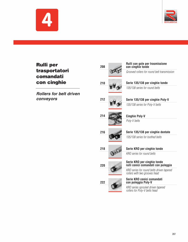
207
Rulli per trasportatoricomandati con cinghie
Rollers for belt drivenconveyors
4
Serie 135/138 per cinghie dentate 135/138 series for toothed belts
Serie KRO per cinghie tonde KRO series for round belts
Serie 135/138 per cinghie tonde135/138 series for round belts
Rulli con gole per trasmissione con cinghie tondeGrooved rollers for round belt transmission
Serie 135/138 per cinghie Poly-V135/138 series for Poly-V belts
Cinghie Poly-VPoly-V belts
Serie KRO per cinghie tonde rulli conici comandati con puleggia KRO series for round belts driven taperedrollers with two grooves head
208
210
214
216
218
220
Serie KRO conici comandaticon puleggia Poly-VKRO series sprocket driven tapered rollers for Poly-V belts head
222
212

208
4 Rulli con gole per trasmissione con cinghie tondeGrooved rollers for round belt transmission
Per questo tipo di trasmissione si sono previstirulli folli con gole ricavate direttamente sul tuboin acciaio, soluzione molto semplice edeconomica.Le cinghie devono avere una sezione di Ø 4-5 mm.o al massimo Ø 8 mm.I rulli possono essere della serie GL, GM e 117,le cui caratteristiche sono presentate nel capitolo1, in esecuzione “E” (1 gola) o in esecuzione“F” (2 gole), con tubo in acciaio normale “N”,con zincatura “J” e “Z” oppure con rivestimentoin PVC “P”.Poiché la velocità di trasporto può essereelevata, anche se con carichi contenuti, occorreprestare particolare attenzione nella scelta deirulli in rapporto alle sollecitazioni dinamiche.
Esempi di codice di ordinazioneSi dovrà aggiungere le sigle “E” (1 gola) oppure“F” (2 gole) all’esecuzione del tubo del rulloprescelto.
Esempi:GL/12 12R 50JE 500GM/15 15R 76NEP 800117/12 12RI 50IF 600
Tutte le quote sono espresse in mm.
Per maggiori dettagli vedere capitolo "Indicazionidi impiego e criteri di progettazione" da pag 70.
I rulli serie 117 con gole vengono forniti inesecuzione antistatica.
Idle rollers with grooves made directly on the steeltube are intended for round belts transmission asa very simple and economical solution. The belts should have a section of Ø 4-5 mm ormax. Ø 8 mm. Rollers may be “GL, GM and 117” series, whosecharacteristics are described in chapter 1, inexecution “E” (1 groove) or in execution “F” (2grooves), with standard steel tube “N”, withelectrolytic zinc-plating “J” and “Z” or PVCcoating “P”.Since the handling speed may be high, eventhough with restrained loads, particular care shallbe taken in choosing the rollers in relation to theexpected dynamic stresses.
Ordering code The letter “E” (1 groove) or “F” (2 grooves) mustbe added to the tube execution of the selectedroller.
Examples:GL/12 12R 50JE 500GM/15 15R 76NEP 800117/12 12RI 50IF 600
All dimensions are in mm.
For further details please refer to chapter"Application indications and design criteria" atpage 70.
The rollers of 117 series with grooves aresupplied in antistatic execution as standard.
Tipo / Type D Di a b r
32 24 20 16 2,5
40 30 32 20 5
50 38 32 20 5
50 38 32 20 5
60 48 32 20 5
76 64 32 20 5
50 38 32 20 5
60 48 32 20 5
76 64 32 20 5
40 30 35 20 5
50 38 35 20 5
60 48 35 20 5
GL/60-62
GL/8
GL/10-11-12
GM/12-15
117/8-10-11-12
Nella versione con asse a molla le gole sono eseguite nel lato opposto alla compressione dell'asse.With spring shaft version, grooves are made on the opposite roller size.

209
Rulli per trasportatori comandati con cinghieRollers for belt driven conveyors
PULEGGE PER ACCUMULO
Quando si realizzano tratti di accumulo con tras -mis sione a cinghie tonde incrociate, con asse dicomando sottostante ortogonale ai rulli, è pos -sibile ridurre in parte la spinta tra i colli inse ren -do sull’albero delle puleggette, quali elemento dicomando per le cinghie, consentendo così al l’al -b ero di ruotare esercitando minor attrito.Sono prodotte in POM color grigio.
BELT WHEELS FOR ACCUMULATION
When you build accumulation sections withcrossed round belt transmission, with driving shaftmounted lengthwise under the rollers path, it ispossible to reduce partially the pressure betweenthe conveyed loads by connecting the belt withsingle belt wheels on the shaft, producing lessfriction on the driving shaft itself.Belt wheels are produced in POM grey colour.
Codice / Code Note / Notes Peso / WeightdaN
RSV J178 puleggia per velocità fino a 30 m/minbelt wheel for speed up to 30 m/min 0,022
RSV PD01 puleggia per velocità fino a 40 m/minbelt wheel for speed up to 40 m/min 0,044
RSV J178
RSV PD01
(*) da determinare consultando i fornitori delle cinghie, in rapporto alle caratteristiche delle stesse ed ai diametri diavvolgimento.
(*) to be decided by contacting the belts manufacturers regarding belts features and winding diameters.

210
SerieSeries 135/1384
RULLI COMANDATI E FRIZIONATI CON PULEGGIA A DOPPIA GOLA PER CINGHIOLI TONDI
Questi rulli hanno le stesse caratteristiche ecombinazioni delle serie 135 (comandati) e138 (frizionati) presentate a pag.164 e 178, macon la puleggia per cinghioli tondiintercambiabili fra di loro, al posto dei pignoni.Con queste pulegge si evitano quindi ledeformazioni come nel caso di gole ricavatesul tubo.La puleggia è realizzata in Poliammide nerocon 2 gole per cinghioli tondi Ø 4 o 5 mm.La trasmissione quindi può esserecompletamente carterata con il minimoingombro, senza che i cinghioli vengano acontatto con i colli trasportati, provocandonelo sbandamento o compromettendo lacapacità di trascinamento.I rulli sono dotati di cuscinetti radiali diprecisione 6002-2RZ.Si consiglia di non superare la velocitàd’avanzamento di 0,8 m/s, dovuta al sistemadi trasmissione.
Nell’indicare il codice d’ordinazione vannoriportati il tipo, il diametro e l’esecuzione asse, ildiametro e l’esecuzione tubo, la lunghezza “C”.
Esempio di codice d’ordinazione135/F1 14R 50Z 650138/F2 14RI 50V 600
Tutte le quote sono espresse in mm.
FIXED AND FRICTION DRIVENROLLERS WITH TWO GROOVES HEAD FOR ROUND BELTS
These rollers have the same features as theseries 135 (driven) and 138 (friction) shown atpage 164 and 178, but with a grooved head forround belts instead of pinion sprockets. This solution maintains tube concentricity.The round belt head is made of Polyamide inblack colour with 2 grooves for round belt Ø 4 or5 mm.The transmission can be completely enclosedwith minimum space, without contact with theconveyed loads.This avoids possible belt misalignment andmaintains driving force.The rollers have precision 6002-2RZ ball bearings. We suggest not exceeding a handling speed of0,8 m/s, due to the transmission system
In indicating the ordering code, please specifythe type, the shaft diameter and execution, thetube diameter and execution, the “C” length.
Ordering code example135/F1 14R 50Z 650138/F2 14RI 50V 600
All dimensions are in mm.
13 13.5
ø37
.8
r5
per cinghie tondefor round belts

211
Rulli per trasportatori comandati con cinghieRollers for belt driven conveyors
CAPACITÀ DI CARICO “PC”La capacità di carico e di trascinamento “Pc”del rullo risulta essere il valore ricavato dallatabella, considerando sempre: Pc ≥ Pdove P è il carico effettivo sul rullo.I valori indicati sono validi per velocità dirotazione fino a 500 giri/min.
LOAD CAPACITY “PC”The “Pc” load and dragging capacity shallresult in being the value obtained from thetable, always considering that: Pc ≥ Pwhere P is the real load on the roller.The values of the table are referring to 500rev/min max. speed.
Legenda delle sigle di esecuzioneR = asse forato e filettatoJ = asse con zincatura elettrolitica I = asse in acciaio inox AISI 304
Z = tubo zincato a caldo (sendzimir)V = tubo in PVC rigidoJ = tubo con zincatura elettrolitica N = tubo in acciaio normaleI = tubo in acciaio inox AISI 304 P = tubo con guaina morbida in PVC
Execution codes captionR = drilled and threaded shaftJ = zinc-plated shaftI = AISI 304 stainless steel shaft
Z = hot dip zinc-plated tube (sendzimir)V = rigid PVC tubeJ = zinc-plated tubeN = normal steel tubeI = AISI 304 stainless steel tubeP = soft PVC lagging
Nota:Questi rulli possono essere forniti in:- esecuzione con cuscinetti inox AISI 440- esecuzione antistatica, con tubi in acciaioAttenzione: per rulli frizionati serie 138 esecuzioni conguaina in PVC o altri rivestimenti riducono la capacitàdi spinta.
Note:These rollers can be supplied with:- AISI 440 stainless steel bearings- antistatic execution for steel tubesNote: for friction 138 series rollers executions with PVCsleeves or other coatings reduce the pressure force.
Tipo / Type
50
60
30
30
30
30
30
30
30
30
30
30
30
30
30
30
30
30
30
30
≤ 400 500 600 700 800 900 1000 1200 1400
Rulli con tubo in acciaio - Steel tube rollers
50
63
15
15
15
15
12
15
7
15
5
11 8 5
Rulli con tubo in PVC - PVC tube rollers
135-138/F1
135-138/F2
Lungh. / Length. C
daN
Portata / Capacity
Tipo / Type
14 R50
60Z 130
1600
1600
1,5
1,5J-I J-N-I-P
0,721
0,791
0,030
0,034
0,452
0,522
0,018
0,022
14 R50
63V 130
800
1000
2,8
3J-I -
0,550
0,596
0,018
0,021
0,281
0,327
0,006
0,008
Con tubo in acciaio - with steel tube
Serie 135 rulli comandati - fixed drive rollers
Con tubo in PVC - with PVC tube
135/F1
135/F2
Codice di ordinazione / Ordering codes
14 R50
60Z 130
1200
1400
1,5
1,5J-I J-N-I-P
0,721
0,791
0,030
0,034
0,452
0,522
0,018
0,022
14 R50
63V 130
800
1000
2,8
3J-I -
0,550
0,596
0,018
0,021
0,281
0,327
0,006
0,008
Con tubo in acciaio - with steel tube
Serie 138 rulli frizionati - friction drive rollers
138/F1
138/F2
d(ø) esec.
Asse / Shaft
D (ø) esec. min. max.
Tubo / Tube Lungh. / Length. Cs
daN daNEsec. asseShaft exec.
Esec. tuboTube exec.
C=200 al cmdaN daN
C=200 al cmPeso / WeightOpzioni / Options
Peso parti rotantiRotating parts weight
Con tubo in PVC - with PVC tube
D (ø)
TuboTube

212
SerieSeries
4 135/138
RULLI COMANDATI E FRIZIONATI CONPULEGGIA PER CINGHIE FLESSIBILI POLY-V
Questi rulli hanno le stesse caratteristiche ecombinazioni delle serie 135 (comandati) e138 (frizionati) presentate a pag.164 e 178, macon la puleggia per cinghie flessibili Poly-Vintercambiabili fra di loro, al posto dei pignoni. La trasmissione con anelli di cinghie Poly-V èun sistema innovativo e performante.La puleggia è realizzata in Poliammide nerocon 9 gole profilo a V passo 2,34 mm formaPJ, ISO 9981 DIN 7867.Gli anelli di cinghia Poly-V standard sonopreviste con 2 coste, ma la puleggia ammetteanche le versioni con 3 o 4 coste.Già la versione con 2 coste può trasmettere unacoppia doppia rispetto ai cinghioli tondi,consentendo normalmente di concatenare almeno20 rulli con motorizzazione posta al centro. E’ consentita una velocità d’avanzamento fino a1,5 m/s in modo silenzioso per i rulli comandatiserie 135, ma si consiglia di non superare lavelocità d’avanzamento di 0,8 m/s per i rullifrizionati serie 138, dovuto al sistema di frizionecon possibilità di accumuli prolungati dei colli. I rulli sono dotati di cuscinetti radiali diprecisione 6002-2RZ.
Nell’indicare il codice d’ordinazione vannoriportati il tipo, il diametro e l’esecuzione asse, ildiametro e l’esecuzione tubo, la lunghezza “C”.
Esempio di codice d’ordinazione135/V1 14R 50Z 700138/V2 14RI 50V 500
Tutte le quote sono espresse in mm.
FIXED AND FRICTION DRIVEN ROLLERSWITH POLY-V FLEXIBLE BELT HEAD
These rollers have the same features as the series135 (driven) and 138 (friction) shown at page164 and 178, but with an interchangeable Poly-Vflexible belt head instead of pinion sprockets. The Poly-V belt is a new and effective system. The drive head is made of Polyamide in blackcolour with 9 grooves for V-rib, pitch 2,34 mmPJ form, ISO 9981 DIN 7867.Standard Poly-V belts have 2 ribs but it is alsopossible to use belts with 3 or 4 ribs.Even when using elastic belts with only 2 ribs, atransfer of twice the amount as that delivered bycomparable round belts is possible.The standard 2-rib belt allows up to 20 rollers tobe looped together with a central drive.Achieving a handling speed of up to 1,5 m/s, withlow noise levels using driven roller series 135.However, we suggest not exceeding a handlingspeed of 0,8 m/s with friction roller series 138,due to the friction system and the possibility ofunits accumulating. The rollers have precision 6002-2RZ ball bearings.
In indicating the ordering code, please specify thetype, the shaft diameter and execution, the tubediameter and execution, the C length.
Ordering code example135/V1 14R 50Z 700138/V2 14RI 50V 500
All dimensions are in mm.
per cinghie Poly-Vfor Poly-V belts

213
Rulli per trasportatori comandati con cinghieRollers for belt driven conveyors
Legenda delle sigle di esecuzioneR = asse forato e filettatoJ = asse con zincatura elettrolitica I = asse in acciaio inox AISI 304
Z = tubo zincato a caldo (sendzimir)V = tubo in PVC rigidoJ = tubo con zincatura elettrolitica N = tubo in acciaio normaleI = tubo in acciaio inox AISI 304 P = tubo con guaina morbida in PVC
Execution codes captionR = drilled and threaded shaftJ = zinc-plated shaftI = AISI 304 stainless steel shaft
Z = hot dip zinc-plated tube (sendzimir)V = rigid PVC tubeJ = zinc-plated tubeN = normal steel tubeI = AISI 304 stainless steel tubeP = soft PVC lagging
Nota:Questi rulli possono essere forniti in:- esecuzione con cuscinetti inox AISI 440- esecuzione antistatica, con tubi in acciaioAttenzione: per rulli frizionati serie 138esecuzioni con guaina in PVC o altririvestimenti riducono la capacità di spinta.
Note:These rollers can be supplied with:- AISI 440 stainless steel bearings- antistatic execution for steel tubesNote: for friction 138 series rollersexecutions with PVC sleeves or othercoatings reduce the pressure force.
Tipo / Type
14 R50
60Z 130
1600
1600
1,5
1,5J-I J-N-I-P
0,721
0,791
0,030
0,034
0,452
0,522
0,018
0,022
14 R50
63V 130
800
1000
2,8
3J-I -
0,550
0,596
0,018
0,021
0,281
0,327
0,006
0,008
Con tubo in acciaio - with steel tube
Serie 135 rulli comandati - fixed drive rollers
Con tubo in PVC - with PVC tube
135/V1
135/V2
Codice di ordinazione / Ordering codes
14 R50
60Z 130
1200
1400
1,5
1,5J-I J-N-I-P
0,721
0,791
0,030
0,034
0,452
0,522
0,018
0,022
14 R50
63V
130
-
800
1000
2,8
3J-I -
0,550
0,596
0,018
0,021
0,281
0,327
0,006
0,008
Con tubo in acciaio - with steel tube
Serie 138 rulli frizionati - friction drive rollers
138/V1
138/V2
d(ø) esec.
Asse / Shaft
D (ø) esec. min. max.
Tubo / Tube Lungh. / Length. Cs
daN daNEsec. asseShaft exec.
Esec. tuboTube exec.
C=200 al cmdaN daN
C=200 al cmPeso / WeightOpzioni / Options
Peso parti rotantiRotating parts weight
Con tubo in PVC - with PVC tube
CAPACITÀ DI CARICO “PC”La capacità di carico e di trascinamento “Pc”del rullo risulta essere il valore ricavato dallatabella, considerando sempre: Pc ≥ Pdove P è il carico effettivo sul rullo.I valori indicati sono validi per velocità dirotazione fino a 500 giri/min.
LOAD CAPACITY “PC”The “Pc” load and dragging capacity shallresult in being the value obtained from thetable, always considering that: Pc ≥ Pwhere P is the real load on the roller.The values of the table are referring to 500rev/min max. speed.
Tipo / Type
50
60
30
30
30
30
30
30
30
30
30
30
30
30
30
30
30
30
30
30
≤ 400 500 600 700 800 900 1000 1200 1400
Rulli con tubo in acciaio - Steel tube rollers
50
63
15
15
15
15
12
15
7
15
5
11 8 5
Rulli con tubo in PVC - PVC tube rollers
135-138/V1
135-138/V2
Lungh. / Length. C
daN
Portata / Capacity
D (ø)
TuboTube

214
4 Cinghie Poly-VPoly-V belts
CINGHIE A STOCK
A stock sono previste le cinghie Poly-V per ipassi di rulli più frequenti.Nella scelta occorre considerare:- il diametro primitivo di avvolgimento della
cinghia sta 1 mm sopra la puleggia, quindi Dp = ø puleggia + 2 mm.
- Tensione media consigliata 5%; range ditensione ammessa 4-6%.
- Temperatura di lavoro: -5 / + 80° CPer temperature più basse riferirsi a Rulmeca.
AVAILABLE BELTS
Whe have stock availability of the Poly-V beltsfor the most usual rollers pitchesIn the choice it should be considered:- The primitive wrapping diameter of the belt
is located 1 mm over the head outerdiameter, then Dp = head ø + 2 mm.
- Suggested average belt pretension 5%;pretension admitted range 4-6%.
- Working temperature: - 5 / + 80° CFor lower temperatures please refer to Rul meca.
Coppia trasmissibile da cinghie Poly-V / Transmittable torque by Poly-V belts
Tipo Type
Pretens. 4% / 4% pretens.Coppia / Torque
2PJ
3PJ
1 Nm
1,5 Nm
Pretens. max. / Max pretens.Coppia / Torque
1,4 Nm
2,1 Nm

215
Rulli per trasportatori comandati con cinghieRollers for belt driven conveyors
Cinghie Poly-V flessibili a 2 e 3 coste passo 2,34 profilo J ISO 9982 DIN 7867 / Flexible Poly-V belts with 2 and 3 ribs pitch 2,34 J profile ISO 9982 DIN 7867
*Cinghie con misure standard. Per misure diverse richiedere la disponibilità. / Belts with standard dimensions. For different dimensions please contact us for availibility.
Codice di ordinazioneOrdering codes
Descrizione / DescriptionCoste Ribs N°
Std. Sviluppo cinghia a riposo Released belt length
BELT-2PJ-50
BELT-2PJ-55
BELT-2PJ-60
BELT-2PJ-68
BELT-2PJ-73
BELT-2PJ-75
BELT-2PJ-78
BELT-2PJ-80
BELT-2PJ-90
BELT-2PJ-94
BELT-2PJ-100
BELT-2PJ-105
BELT-2PJ-110
BELT-2PJ-120
BELT-2PJ-125
BELT-2PJ-133
BELT-2PJ-153
BELT-2PJ-160
BELT-2PJ-175
BELT-2PJ-200
BELT-3PJ-50
BELT-3PJ-55
BELT-3PJ-60
BELT-3PJ-68
BELT-3PJ-73
BELT-3PJ-75
BELT-3PJ-78
BELT-3PJ-80
BELT-3PJ-90
BELT-3PJ-94
BELT-3PJ-100
BELT-3PJ-105
BELT-3PJ-110
BELT-3PJ-120
BELT-3PJ-125
BELT-3PJ-133
BELT-3PJ-153
BELT-3PJ-160
BELT-3PJ-175
BELT-3PJ-200
*
*
*
*
*
*
*
*
*
*
*
*
*
*
*
*
*
*
*
Cinghia Poly-V, 2 coste, Rif. PJ 236 / Poly-V belt, 2 ribs, Ref. PJ 236
Cinghia Poly-V, 2 coste, Rif. PJ 246 / Poly-V belt, 2 ribs, Ref. PJ 246
Cinghia Poly-V, 2 coste, Rif. PJ 256 / Poly-V belt, 2 ribs, Ref. PJ 256
Cinghia Poly-V, 2 coste, Rif. PJ 270 / Poly-V belt, 2 ribs, Ref. PJ 270
Cinghia Poly-V, 2 coste, Rif. PJ 282 / Poly-V belt, 2 ribs, Ref. PJ 282
Cinghia Poly-V, 2 coste, Rif. PJ 286 / Poly-V belt, 2 ribs, Ref. PJ 286
Cinghia Poly-V, 2 coste, Rif. PJ 288 / Poly-V belt, 2 ribs, Ref. PJ 288
Cinghia Poly-V, 2 coste, Rif. PJ 290 / Poly-V belt, 2 ribs, Ref. PJ 290
Cinghia Poly-V, 2 coste, Rif. PJ 314 / Poly-V belt, 2 ribs, Ref. PJ 314
Cinghia Poly-V, 2 coste, Rif. PJ 316 / Poly-V belt, 2 ribs, Ref. PJ 316
Cinghia Poly-V, 2 coste, Rif. PJ 336 / Poly-V belt, 2 ribs, Ref. PJ 336
Cinghia Poly-V, 2 coste, Rif. PJ 346 / Poly-V belt, 2 ribs, Ref. PJ 346
Cinghia Poly-V, 2 coste, Rif. PJ 356 / Poly-V belt, 2 ribs, Ref. PJ 356
Cinghia Poly-V, 2 coste, Rif. PJ 376 / Poly-V belt, 2 ribs, Ref. PJ 376
Cinghia Poly-V, 2 coste, Rif. PJ 388 / Poly-V belt, 2 ribs, Ref. PJ 388
Cinghia Poly-V, 2 coste, Rif. PJ 416 / Poly-V belt, 2 ribs, Ref. PJ 416
Cinghia Poly-V, 2 coste, Rif. PJ 442 / Poly-V belt, 2 ribs, Ref. PJ 442
Cinghia Poly-V, 2 coste, Rif. PJ 456 / Poly-V belt, 2 ribs, Ref. PJ 456
Cinghia Poly-V, 2 coste, Rif. PJ 486 / Poly-V belt, 2 ribs, Ref. PJ 486
Cinghia Poly-V, 2 coste, Rif. PJ 536 / Poly-V belt, 2 ribs, Ref. PJ 536
Cinghia Poly-V, 3 coste, Rif. PJ 236 / Poly-V belt, 3 ribs, Ref. PJ 236
Cinghia Poly-V, 3 coste, Rif. PJ 246 / Poly-V belt, 3 ribs, Ref. PJ 246
Cinghia Poly-V, 3 coste, Rif. PJ 256 / Poly-V belt, 3 ribs, Ref. PJ 256
Cinghia Poly-V, 3 coste, Rif. PJ 270 / Poly-V belt, 3 ribs, Ref. PJ 270
Cinghia Poly-V, 3 coste, Rif. PJ 282 / Poly-V belt, 3 ribs, Ref. PJ 282
Cinghia Poly-V, 3 coste, Rif. PJ 286 / Poly-V belt, 3 ribs, Ref. PJ 286
Cinghia Poly-V, 3 coste, Rif. PJ 288 / Poly-V belt, 3 ribs, Ref. PJ 288
Cinghia Poly-V, 3 coste, Rif. PJ 290 / Poly-V belt, 3 ribs, Ref. PJ 290
Cinghia Poly-V, 3 coste, Rif. PJ 314 / Poly-V belt, 3 ribs, Ref. PJ 314
Cinghia Poly-V, 3 coste, Rif. PJ 316 / Poly-V belt, 3 ribs, Ref. PJ 316
Cinghia Poly-V, 3 coste, Rif. PJ 336 / Poly-V belt, 3 ribs, Ref. PJ 336
Cinghia Poly-V, 3 coste, Rif. PJ 346 / Poly-V belt, 3 ribs, Ref. PJ 346
Cinghia Poly-V, 3 coste, Rif. PJ 356 / Poly-V belt, 3 ribs, Ref. PJ 356
Cinghia Poly-V, 3 coste, Rif. PJ 376 / Poly-V belt, 3 ribs, Ref. PJ 376
Cinghia Poly-V, 3 coste, Rif. PJ 388 / Poly-V belt, 3 ribs, Ref. PJ 388
Cinghia Poly-V, 3 coste, Rif. PJ 416 / Poly-V belt, 3 ribs, Ref. PJ 416
Cinghia Poly-V, 3 coste, Rif. PJ 442 / Poly-V belt, 3 ribs, Ref. PJ 442
Cinghia Poly-V, 3 coste, Rif. PJ 456 / Poly-V belt, 3 ribs, Ref. PJ 456
Cinghia Poly-V, 3 coste, Rif. PJ 486 / Poly-V belt, 3 ribs, Ref. PJ 486
Cinghia Poly-V, 3 coste, Rif. PJ 536 / Poly-V belt, 3 ribs, Ref. PJ 536
288
240
252,5
259,8
274
275,3
280,1
284,5
306
313,5
325,5
336,6
347
363,1
375
388
429
438,5
466
515
288
240
252,5
259,8
274
275,3
280,1
284,5
306
313,5
325,5
336,6
347
363,1
375
388
429
438,5
466
515
2
2
2
2
2
2
2
2
2
2
2
2
2
2
2
2
2
2
2
2
3
3
3
3
3
3
3
3
3
3
3
3
3
3
3
3
3
3
3
3
Rif. CostruttoreManufact. Ref.
PJ 236
PJ 246
PJ 256
PJ 270
PJ 282
PJ 286
PJ 288
PJ 290
PJ 314
PJ 316
PJ 336
PJ 346
PJ 356
PJ 376
PJ 388
PJ 416
PJ 442
PJ 456
PJ 486
PJ 536
PJ 236
PJ 246
PJ 256
PJ 270
PJ 282
PJ 286
PJ 288
PJ 290
PJ 314
PJ 316
PJ 336
PJ 346
PJ 356
PJ 376
PJ 388
PJ 416
PJ 442
PJ 456
PJ 486
PJ 536
Passo rulliRoller pitch
47-50
53-56
60-63
64-68
71-74
73-75
75-78
77-80
88-91
92-95
98-102
104-108
109-113
118-122
124-129
130-135
152-157
157-162
171-176
197-202
47-50
53-56
60-63
64-68
71-74
73-75
75-78
77-80
88-91
92-95
98-102
104-108
109-113
118-122
124-129
130-135
152-157
157-162
171-176
197-202
Rulmeca_CatUnit@215#.qxd 22/01/19 15:47 Pagina 215

216
SerieSeries 135/1384
RULLI COMANDATI E FRIZIONATI CON PULEGGIA PER CINGHIE DENTATE
Questi rulli vengono forniti su richiesta e hannole stesse caratteristiche e combinazioni delleserie 135 e 138 presentate a pag 164 e a pag.178, ma con la puleggia per cinghia dentata alposto dei pignoni, nelle versione comandatiserie 135 e frizionati serie 138, inter cam bi a bilifra loro.La puleggia è realizzata in POM color nero,passo 8 mm, per anelli di cinghia Poly-chain GTcon larghezza 11,2 mm e similari, nonchécompatibile con le cor ris pon den ti cinghie HTD.Occorre quindi osservare le specifiche dei pro -dut tori di cinghie per il calcolo della trasmis -sione, il passo dei rulli e la tolleranza, in rap por -to all’eventuale pretensionamento. Consigliamocomunque di contattarci per ogni evenienza.I rulli sono previsti con tubo in acciaio zincatosendzimir (esec. Z) oppure in speciale PVCantiurto (esec. V), dotati di cuscinetti radiali diprecisione 6002-2RZ.
Nell’indicare il codice d’ordinazione vanno ri -por tati il tipo, il diametro e l’esecuzione asse, ildiametro e l’esecuzione tubo, la lunghezza “C”
Esempi di codice d’ordinazione135/8P 14R 50Z 650138/8Q 14R 60Z 700
Tutte le quote sono espresse in mm.
FIXED AND FRICTION DRIVEN ROLLERSWITH TOOTHED BELT HEAD
These rollers can be supplied on request andhave the same features of the series 135 and138 shown at page 164 and at page 178 butwith a toothed belt head instead of pinionsprockets in the driven versions of 135 seriesand friction 138 series, (interchangeable).The toothed belt head is made of POM blackcolour, pitch 8 mm, for belt rings Poly-chainGT width 11,2 mm or similar, compatible withthe corresponding HTD belts.It is important then to follow the beltmanufacturers’ specifications for the transmissioncalculation, the rollers pitch and tolerance inrelation with the eventual initial tension. Wesuggest contacting us in this case.The rollers have sendzimir zinc-plated tube(Z. exec.) or special anti-shock PVC (V exec.)with precision radial 6002-2RZ.
In indicating the ordering code, pleasespecify the type, the shaft diameter andexecution, the tube diameter and execution,the C length.
Ordering code example135/8P 14R 50Z 650138/8Q 14R 60Z 700
All dimensions are in mm.
per cinghie dentatefor toothed belts

217
Rulli per trasportatori comandati con cinghieRollers for belt driven conveyors
135/8P
135/8Q
Tipo / Typed(ø) esec. D (ø) esec. min. max.
Tubo / Tube Lungh. / Length. C p Z Dp (ø) De (ø) sdaN daN daN daN
Asse/Shaft Tubo/Tube C=200 al cm C=200 al cmPeso / WeightCodice di ordinazione / Ordering codes Opzioni / Options
Asse / Shaft
14 R50
60
50
60
Z 130 1600 8 18 45,80 49,00 1,5 J-I J-N-I-P
14 R Z 130 1600 8 20 50,93 55,00 1,5 J-I J-N-I-P
0,71
0,78
0,73
0,80
0,030
0,034
0,030
0,034
0,442
0,512
0,462
0,532
0,018
0,022
0,018
0,022
135/8P
135/8Q
14 R50
63
50
63
V 130800
1000
800
1000
8 18 45,80 49,002,8
3J-I -
14 R V 130 8 20 50,93 55,002,8
3J-I -
0,54
0,58
0,56
0,61
0,018
0,021
0,018
0,021
0,272
0,317
0,292
0,337
0,006
0,008
0,006
0,008
Peso parti rotantiRotating parts weight
Con tubo in acciaio - with steel tube
Con tubo in PVC - with PVC tube
Serie 135 rulli comandati / fixed drive rollers
138/8Q
Tipo / Typed(ø) esec. D (ø) esec. min. max.
Tubo / Tube Lungh. / Length. C p Z Dp (ø) De (ø) sdaN daN daN daN
Asse/Shaft Tubo/Tube C=200 al cm C=200 al cmPeso / WeightCodice di ordinazione / Ordering codes Opzioni / Options
Asse / Shaft
50
6014 R Z 130 1600 8 20 50,93 55,00 1,5 J-I J-N-I-P
0,73
0,80
0,030
0,034
0,462
0,532
0,018
0,022
138/8Q50
63
800
100014 R V 130 8 20 50,93 55,00
2,8
3J-I -
0,56
0,61
0,018
0,021
0,292
0,337
0,006
0,008
Peso parti rotantiRotating parts weight
Con tubo in acciaio - with steel tube
Con tubo in PVC - with PVC tube
ESECUZIONI ASSI A RICHIESTA / SHAFT EXECUTION ON REQUESTSerie 138 rulli frizionati / friction drive rollers
Nota:questi rulli possono essere forniti:- con cuscinetti in acciaio inox- in esecuzione antistatica
Legenda delle sigle di esecuzioneR = asse forato e filettatoJ = asse con zincatura elettroliticaI = asse in acciaio inox AISI 304
Z = tubo zincato a caldo (sendzimir)V = tubo in PVC rigidoJ = tubo con zincatura elettroliticaN = tubo in acciaio normaleI = tubo in acciaio inox AISI 304P = rivestimento con guaina morbida in PVC
Note:these rollers can be supplied - with stainless steel bearings- in antistatic version
Execution codes captionR = drilled and threaded shaftJ = zinc-plated shaftI = AISI 304 stanless steel shaft
Z = hot dip zinc-plated tube (sendzimir)V = rigid PVC tubeJ = zinc-plated tubeN = normal steel tubeI = AISI 304 stainless steel shaftP = soft PVC lagging

218
SerieSeries KRO4
RULLI CONICI CON GOLE PERTRASMIS SIONE CON CINGHIE TONDE
Questi rulli vengono forniti su richiesta e sonoottenuti mediante calettamento di manicottitroncoconici in Polipropilene sul rullo baseØ50. Nella parte sporgente del diametro minoresono ricavate sul tubo in acciaio 2 gole per latrasmissione con cinghioli tondi Ø4-5 mm.Le caratteristiche generali sono le stesse dellaserie KRO (rullo base 117) presentata a pag.194, salvo la diversa configurazione.
I rulli sono dotati di cuscinetti radiali diprecisione 6002-2RZ e sono forniti inesecuzione antistatica nella versionestandard.
Nell’indicare il codice d’ordinazione vannoriportati il tipo, il diametro e l’esecuzione asse,il codice e l’esecuzione tubo, la lunghezza “C”.
Esempio di codice d’ordinazioneKRO/F2 12R 91ZKF 700
Tutte le quote sono espresse in mm.
TAPERED ROLLERS WITH GROOVESFOR ROUND BELT TRANSMISSION
These rollers are supplied on request and areobtained by assembling Polypropylene conesleeves on the base roller Ø 50. On the protruding part of the smallerdiameter there are 2 grooves on the tube forround belt transmission Ø4-5 mm. Thegeneral features are the same of KRO series(base roller 117 series) shown at page 194but with a different lay-out.
The rollers have precision radial 6002-2RZbearings and are supplied in antistaticexecution as standard.
In indicating the ordering code, pleasespecify the type, the shaft diameter andexecution, the tube code and execution, the Clength.
Ordering code exampleKRO/F2 12R 91ZKF 700
All dimensions are in mm.
per cinghie tondefor round belts

219
Rulli per trasportatori comandati con cinghieRollers for belt driven conveyors
KRO/F2
Tipo / Typed(ø) esec. cod. esec.
Tubo / Tube Lungh. / LengthC
Lungh. / LengthBu
Rullo baseBase Roller D (ø) D1 (ø) Ri
Codice di ordinazione / Ordering codesAsse / Shaft
12 R
65
71
72
77
78
84
85
90
91
96
97
103
104
109
110
ZFK
300
350
400
450
500
550
600
650
700
750
800
850
900
950
1000
195
245
295
345
395
445
495
545
595
645
695
745
795
845
895
65,6
72,0
72,0
78,5
78,5
85,0
85,0
91,3
91,3
97,6
97,6
104,0
104,0
110,3
110,3
52,5
55,8
52,5
55,8
52,5
55,8
52,5
55,8
52,5
55,8
52,5
55,8
52,5
55,8
52,5
720
770
720
770
720
770
720
770
720
770
720
770
720
770
720
0,98
1,16
1,32
1,53
1,69
1,91
2,07
2,31
2,47
2,72
2,89
3,16
3,33
3,62
3,78
KRO-117
Peso totaleTotal weight
daN
Nota:questi rulli possono essere forniti in esecuzione:- con cuscinetti in acciaio inox- con asse e tubo interno inox AISI 304
Legenda delle sigle di esecuzione:R = asse forato e filettato Z = tubo con zincatura a caldo (sendzimir)K = manicotti conici in polipropileneF = tubo con 2 gole per cinghie tonde
CAPACITÀ DI CARICOSi consiglia di non superare il carico di 35 daNper rullo, condizionato dal tipo di trasmissione.
Note:these rollers can be supplied:- with stainless steel balls bearings- with stainless steel AISI 304 shaft and internal tube
Execution codes caption:R = drilled and threaded shaftZ = hot dip zinc-plated tube (sendzimir)K = tapered polypropylene sleevesF = tube with 2 grooves for round belts
LOAD CAPACITYWe suggest not exceeding 35 daN per roller,according to the type of transmission.

220
SerieSeries KRO4 per cinghie tonde
for round belts
RULLI CONICI COMANDATI CON PULEGGIAA DOPPIA GOLA PER TRASMISSIONE CONCINGHIOLI TONDI
Ideali per realizzare curve nel trasporto di collileggeri, questi rulli sono ottenuti mediantecalettamento di manicotti troncoconici inPolipropilene sul rullo base Ø 50. Dal lato deldiametro minore è inserita ad innesto nellatestata di accoppiamento la puleggia con 2 goleper la trasmissione con cinghioli tondiØ4-5 mm, intercambiabile con le altre pulegge,evitando quindi le deformazioni come nel casodi gole ricavate sul tubo.La puleggia è realizzata in Poliammide nero,mentre le caratteristiche generali sono le stessedei rulli conici comandati serie KRO (rullo base135) presentata a pag. 202, salvo la diversaconfigurazione.I rulli sono dotati di cuscinetti radiali di preci -sione 6002-2RZ.
Nell’indicare il codice d’ordinazione vannoripor tati il tipo, il codice e l’esecuzione asse, ilcodice e l’esecuzione tubo, la lunghezza “C”
Esempio di codice d’ordinazioneKRO/FM 14R 96ZK 700
Tutte le quote sono espresse in mm.
DRIVEN TAPERED ROLLERS WITHTWO GROOVES HEAD FOR ROUNDBELT TRANSMISSION
These rollers are ideal to build curves in lightunit handling and are obtained by keyingPolypropylene cone sleeves on the base rollerØ 50. On the side of the smaller diameterthere is a sprocket with 2 grooves for roundbelt transmission Ø4-5 mm, interchangeablewith other heads, thus avoiding deformationsas in case of grooves on the tube. The sprocket is made in black Polyamide,while the general features are the same as forthe driven sprocket tapered KRO series (baseroller 135 series) shown at page 202 but witha different lay-out.The rollers have precision radial 6002-2RZbearings.
In indicating the ordering code, pleasespecify the type, the shaft code andexecution, the tube code and execution, the Clength.
Ordering code exampleKRO/FM 14R 96ZK 700
All dimensions are in mm.

221
Rulli per trasportatori comandati con cinghieRollers for belt driven conveyors
KRO/FM
Tipo / Typed(ø) esec. cod. esec.
Tubo / Tube Lungh. / LengthC
Lungh. / LengthBu
Rullo baseBase Roller D (ø) D1 (ø) Ri
Codice di ordinazione / Ordering codesAsse / Shaft
14 R
72
77
78
84
85
90
91
96
97
103
104
109
110
ZK
350
400
450
500
550
600
650
700
750
800
850
900
950
295
345
395
445
495
545
595
645
695
745
795
845
895
72
78,5
78,5
85
85
91,3
91,3
97,6
97,6
104
104
110,3
110,3
52,5
55,6
52,5
55,6
52,5
55,6
52,5
55,6
52,5
55,6
52,5
55,6
52,5
770
820
770
820
770
820
770
820
770
820
770
820
770
1,42
1,54
1,69
1,81
1,97
2,04
2,26
2,38
2,58
2,70
2,97
3,03
3,26
KRO-135
Peso totaleTotal weight
daN
Nota:questi rulli possono essere forniti in esecuzione:- con cuscinetti in acciaio inox- con asse e tubo interno inox AISI 304 - frizionati tipo KRO/FF (rullo base 135/F1)
Legenda delle sigle di esecuzione:R = asse forato e filettato Z = tubo con zincatura a caldo (sendzimir)K = manicotti conici in polipropilene
CAPACITÀ DI CARICOSi consiglia di non superare il carico di 35 daNper rullo, condizionato dal tipo di trasmissione.
Note:these rollers can be supplied:- with stainless steel balls bearings- with stainless steel AISI 304 shaft and internal tube- friction tipe KRO/FF (base roller 135/F1)
Execution codes caption:R = drilled and threaded shaftZ = hot dip zinc-plated tube (sendzimir)K = tapered polypropylene sleeves
LOAD CAPACITYWe suggest not exceeding 35 daN per roller,according to the type of transmission.

222
SerieSeries KRO4
RULLI CONICI COMANDATI CONPULEGGIA PER TRASMISSIONE CONCINGHIE FLESSIBILI POLY-V
Innovativi per il sistema di trasmissione, idealiper realizzare curve nel trasporto di colli leggerie medi, questi rulli sono ottenuti mediantecalettamento di manicotti tron coconici inPolipropilene sul rullo base Ø 50. Dal lato deldiametro minore è inserita ad innesto nellatestata di accoppiamento la puleggia con 9 goleprofilo a V passo 2,34 mm forma PJ, ISO 9981DIN 7867, intercambiabile con le altre pulegge.La trasmissione quindi può essere facilmentecarterata, con il minimo ingombro e la massimasicurezza, senza che le cinghie venganoinquinate compromettendone la capacità ditrascinamento.E’ prevista solo la trasmissione con anelli dicinghia Poly-V nella versione molto flessibile a2 coste, per un passo dei rulli all’interno dellacurva I=73,7.Tendenzialmente una curva a 90° può preve -dere i rulli concatenati fra di loro con moto riz -zazione posta al centro.La puleggia è realizzata in Poliammide nero,mentre le caratteristiche generali sono le stessedei rulli conici comandati serie KRO (rullo base3500) presentata a pag 202, salvo la diversaconfigurazione.I rulli sono dotati di cuscinetti radiali di preci -sione 6002-2RZ.
Nell’indicare il codice d’ordinazione vannoriportati il tipo, il diametro e l’esecuzione asse,il codice e l’esecuzione tubo, la lunghezza “C”
Esempio di codice d’ordinazioneKRO/VM 14R 96ZK 700
Tutte le quote sono espresse in mm.
DRIVEN TAPERED ROLLERS FORFLEXIBLE POLY-VEE BELTS
These rollers are ideal to build curves for lightand medium duty, they are obtained byassembling Polypropylene cone sleeves onthe base roller Ø 50. On the protruding part ofthe smaller diameter there is the pinion with 9grooves V profile pitch 2,3, 4 mm shape PJ,ISO 9981 DIN 7867, inserted with anintermediate coupling and interchangeablewith other heads. The transmission can be easily cartered , thuslimiting space consumption, maximizingsafety and preventing damages to the Poly-Vee belts.We foresee just a very flexible two-ribPolyVee belt, for a rollers pitch on inner frameof I=73,7.A 90° curve is typically powedered by adriving unit midway along the curve.The sprocket is made in black Polyamide,while the general features are the same as forthe driven sprocket tapered KRO series (baseroller 3500 series) shown at page 202 butwith a different lay-out.The rollers have precision radial 6002-2RZ.
In indicating the ordering code, pleasespecify the type, the shaft diameter andexecution, the tube code and execution, the Clength.
Ordering code exampleKRO/VM 14R 96ZK 700
All dimensions are in mm.
per cinghie Poly-Vfor Poly-V belts

223
Rulli per trasportatori comandati con cinghieRollers for belt driven conveyors
KRO/VM
Tipo / Typed(ø) esec. cod. esec.
Tubo / Tube Lungh. / LengthC
Lungh. / LengthBu
Rullo baseBase Roller D (ø) D1 (ø) Ri
Codice di ordinazione / Ordering codesAsse / Shaft
14 R
72
77
78
84
85
90
91
96
97
103
104
109
110
ZK
350
400
450
500
550
600
650
700
750
800
850
900
950
295
345
395
445
495
545
595
645
695
745
795
845
895
72,0
78,5
78,5
85,0
85,0
91,3
91,3
97,6
97,6
104,0
104,0
110,3
110,3
52,5
55,8
52,5
55,8
52,5
55,8
52,5
55,8
52,5
55,8
52,5
55,8
52,5
770
820
770
820
770
820
770
820
770
820
770
820
770
1,42
1,54
1,69
1,81
1,97
2,04
2,26
2,38
2,58
2,70
2,97
3,03
3,26
KRO-135
Peso totaleTotal weight
daN
Nota:questi rulli possono essere forniti in esecuzione:- con cuscinetti in acciaio inox- con asse e tubo interno inox AISI 304- frizionati tipo KRO/VF (rullo base 135/V1)
Legenda delle sigle di esecuzione:R = asse forato e filettato Z = tubo con zincatura a caldo (sendzimir)K = manicotti conici in polipropilene
CAPACITÀ DI CARICOSi consiglia di non superare il carico di35 daN per rullo, condizionato dal tipo ditrasmissione.
Note:these rollers can be supplied:- with stainless steel balls bearings- with stainless steel AISI 304 shaft and internal tube- friction tipe KRO/VF (base roller 135/V1)
Execution codes caption:R = drilled and threaded shaftZ = hot dip zinc-plated tube (sendzimir)K = tapered polypropylene sleeves
LOAD CAPACITYWe suggest not exceeding 35 daN per roller,according to the type of transmission.

224
SerieSeries KRO4
R 770/820
73.
7
CINGHIE A STOCK
A stock sono disponibili le cinghie Poly-V dautilizzare in curva per passo interno I=73,7 conuna pretensione prevista del 4-6%., coincidenticon le cinghie per passo I=75 tipo BELT-2PJ-75utilizzate per i tratti rettilineiIl calcolo della trasmissione dipende dalleprestazioni assicurate dal produttore di cinghiee consigliamo eventualmente di contattarci perogni evenienza. Per altre indicazioni sullecinghie Poly-V vedere pag. 212-215.
AVAILABLE BELTS IN STOCK
We have Poly-V belts in stock to be used incurves with inner radium pitch I=73,7 withexpected pre-load pretension of 4-6%matching with the BELT-2PJ-75 belts forpitch l=75 for straight sections.The transmission calculation depends fromthe performances assured by the beltmanufacturer; we suggest contacting us forany requirement. For other indications on thePoly-V belts please see page 212-215.
CINGHIE POLY-V flessibili a 2 coste passo 2,34 profilo J ISO 9982 DIN 7867.
Flexible Poly-V BELTS with 2 ribs pitch 2,34J profile ISO 9982 DIN 7867.
Codice di ordinazioneOrdering codes
Descrizione / DescriptionCoste / Ribs Sviluppo cinghia a riposo Released belt lengthN°
BELT-2PJ-75Cinghia POLY-V, 2 coste, Rif. PJ 286
Poly-V belt, 2 ribs, Ref: PJ 286 275,32
Rif. CostruttoreManufact. Ref.
PJ 286
Passo rulliRoller pitch
73÷75

225
La gamma di prodotti RulmecaRulmeca product range
La gamma Rulmeca per il settore Unit Handling si completa con:The Rulmeca Unit Handling range is completed by:
Motorulli RDRRulmeca Drive Rollers

226
La gamma di prodotti RulmecaRulmeca product range
Mototamburi Unit Handling - Unit Handling Motorized Pulleys
Soluzioni per Magazzini Dinamici - Flow Storage solutions


Rulli Rulmeca S.p.A.Via A. Toscanini 1I-24011 Almè (BG) ItalyTel. +39 035 [email protected]
www.rulmeca.com
8° ED
. UN
IT IT 01-2019
CATALOGO GENERALE GENERAL CATALOGUERULLI E COMPONENTI PER LA MOVIMENTAZIONE DEI COLLI NEI TRASPORTI INDUSTRIALIROLLERS AND COMPONENTS FOR UNIT HANDLING AND INDUSTRIAL APPLICATIONS
Moving ahead.
Tecnologia, sviluppo e sostenibilità:Rulli Rulmeca S.p.A. ha deciso di dare priorità ed attenzione alla riduzione degli impatti ambientali, per questa ragione questo catalogo è stampato su carta certifi cata FSC®.
FSC® è un sistema di certifi cazione che consente al consumatore fi nale di riconoscere i prodotti fabbricati con materie prime che provengono da foreste gestite in modo corretto, dal punto di vista ambientale e sociale.FSC® è stata fondata da un gruppo di associazioni ambientaliste tra cui Greenpeace, Amnesty International Italia, Legambiente, L.I.P.U. e WWF, rappresentanze di popoli indigeni, organizzazioni per la cooperazione allo sviluppo, produttori forestali, lavoratori, industrie del legno, scienziati e tecnici forestali per creare un’alternativa alla distruzione delle foreste.
Technology, development and sustainability:Rulli Rulmeca S.p.A. decided to give priority and attention to the reduction of environmental impact factors, for this reason this catalogue is printed on FSC® certifi ed paper.
FSC® is a certifi cation system allowing the consumer to recognize the products made with rough materials coming from a responsible management of the world’s forests, from an environmental and social point of view.FSC® was founded by a group of environmental associations such as Greenpeace, Amnesty International Italy, Legambiente, L.I.P.U and WWF, representatives of indigenous peoples, organizations for the cooperation for the development, forest producers, workers, wood industries, scientists and forest technicians to create an alternative to the forests destruction.
I diritti di traduzione, di riproduzione e di adattamento, totale o parziale, con qualsiasi mezzo (compresi i microfi lm e le copie fotostatiche) sono riservati per tutti i Paesi. Tutte le dimensioni indicate in questo catalogo sono soggette a tolleranze di lavorazione e, benché i disegni siano fedeli, non sono tuttavia impegnativi.RULLI RULMECA S.p.A. si riserva il diritto di modifi care i prodotti senza alcun preavviso.
Translation, reproduction and adaptation rights, total and partial, with any means (microfi lms and photostatic copies included) are reserved for all the Countries. All dimensions indicated in this catalogue are subjected to machining tolerances and, although drawings are exact, they place the manufacturer under no obligation whatsoever.RULLI RULMECA S.p.A. reserves the right to modify the products at any time without any notice.
Copyright © Gennaio 2019RULLI RULMECA SPA8a edizione
CAT
ALO
GO
GE
NE
RA
LEG
EN
ER
AL
CAT
ALO
GU
EM
ovin
g a
hea
d.
8° ED
. UN
IT IT 01-2019
Rulmeca_copertina@1#.indd 1Rulmeca_copertina@1#.indd 1 17/01/19 09:5817/01/19 09:58