8-bitmicrocontroller mb95200 series smoke detector demo …€¦ · 8-bitmicrocontroller mb95200...
TRANSCRIPT

Fujitsu Microelectronics (Shanghai) Co., Ltd. Application Note
MCU-AN- 500054-E-10
F2MC-8FX FAMILY 8-BITMICROCONTROLLER
MB95200 SERIES
Smoke Detector Demo Reference Solution
APPLICATION NOTE

Smoke Detector Demo Quick Start GuideV1.0
MCU-AN- 500054-E-10 – Page 2
Revision History
Date Author Change of Records 2009-11-4 Kevin Lin V1.0
This manual contains 17 pages.
© 2009 Fujitsu Microelectronics (Shanghai) Co., Ltd.
1. The products described in this manual and the specifications thereof may be changed without prior notice. To obtain up-to-date information and/or specifications, please contact your Fujitsu sales representative or Fujitsu authorized dealer.
2. Fujitsu will not be liable for infringement of copyright, industrial property right, or other rights of a third party caused by the use of information or drawings described in this manual.
3. The contents of this manual may not be transferred or copied without the express permission of Fujitsu.
4. The products contained in this manual are not intended for using for with equipment which requires extremely high reliability such as aerospace equipments, undersea repeaters, nuclear control systems or medical equipments for life support.
5. Some of the products described in this manual may be strategic materials (or special technology) as defined by the Foreign Exchange and Foreign Trade Control Law. In such cases, the products or portions thereof must not be exported without permission as defined under the law.

Smoke Detector Demo Quick Start Guide V1.0
MCU-AN- 500054-E-10 – Page 3
CONTENTS
Revision History ....................................................................................................... 2�
1� Outline ................................................................................................................... 4�
2� Demo Platform ...................................................................................................... 5�
2.1� Platform ................................................................................................................... 5�
3� Features ................................................................................................................ 6�
3.1� High dB Alarm ......................................................................................................... 6�
3.2� Powered by Battery ................................................................................................. 6�
3.3� Low Power Consumption ......................................................................................... 6�
4� Functions .............................................................................................................. 7�4.1� Normal State Indication ........................................................................................... 7�
4.2� Self-test Function .................................................................................................... 7�
4.3� Low Battery Output Warning.................................................................................... 7�
4.4� Automatic Alarm ...................................................................................................... 7�
5� Hardware ............................................................................................................... 8�5.1� System Block Diagram ............................................................................................ 8�
5.2� Schematic ............................................................................................................... 9�
5.3� Modules ................................................................................................................ 10�
6� Firmware ............................................................................................................. 13�6.1� Flow Chart ............................................................................................................. 13�
6.2� Project ................................................................................................................... 15�
7� More Information ................................................................................................ 16�
8� Appendix ............................................................................................................. 17�

Smoke Detector Demo Quick Start GuideV1.0
MCU-AN- 500054-E-10 – Page 4
1 Outline
This Demo board is a smoke detector which is used to detect fire. It is a photoelectric detector that senses the infrared refracted by mote or dust caused by fire. The MCU is Fujitsu MB95202K from MB95200 series.
This demo set supports the following features:
� High dB alarm
� Powered by battery
� Low power consumption

Smoke Detector Demo Quick Start Guide V1.0
MCU-AN- 500054-E-10 – Page 5
2 Demo Platform
2.1 Platform Figure 2.1 shows the platform of smoke detector. The D1 and D2 are alarm LEDs. The key is used for self-test.
Figure 2. 1 Demo platform

Smoke Detector Demo Quick Start GuideV1.0
MCU-AN- 500054-E-10 – Page 6
3 Features
3.1 High dB Alarm The sound is higher than 70dB in the field of 3 meters. When the detector is fixed lower than 5 meters above the floor, it can cover 60 square meters.
3.2 Powered by Battery The detector is battery powered equipment. Two 5# batteries can drive it. It runs at 1.8v to 3.3v DC voltage.
3.3 Low Power Consumption In battery powered system, the power consumption is a key parameter. There is a table below to illuminate the main current consumptions.
test condition dc to dc amplifier MCU others total
3V 65mA (EMH7600) 20mA 10mA 5mA 100mA*3V=300mW
Table 3. 1 Current Consumption
In 3v condition, the total current is 100mA. If it is powered by two 5# batteries which have a capacity of 2300mAh, the batteries can last 958 days which is calculated by this formula:
(2300mAh*1000) / (100mA*24h) =958,
Of course this is an ideal data. The actual time will be shorter. The designer can reduce the power consumption by using low power consumption ICs, reducing the system leak current, and using more prefect firmware and so on.
Smoke Detector Demo Quick Start Guide V1.0
MCU-AN- 500054-E-10 – Page 7
4 Functions
4.1 Normal State Indication When power is on, the D1 and D2 will flash for one time to indicate that the demo works normally.
4.2 Self-test Function In order to test the demo, we can press the key. The buzzer will sound periodically when the key is continuously pressed. That means the detector is on normal state.
4.3 Low Battery Output Warning In this demo set, the DC-DC converter has battery capacity monitor function which can supply a signal to the MCU to warn low battery output happened. When low battery output happened, the buzzer will sound and the LEDs will flash at the same time.
4.4 Automatic Alarm The detector senses the refracted light that reflects the thickness of mote or dust. Stronger light means more mote or dust, and also means high risk of fire. When the thickness of the mote or dust rises up to a threshold, the red fire-alarm light will flash first, then buzzer will sound for 11 seconds later.

Smoke Detector Demo Quick Start GuideV1.0
MCU-AN- 500054-E-10 – Page 8
5 Hardware
5.1 System Block Diagram The demo system contains the following elements and it is shown in Figure 5.1.
-MCU
-DC/DC boost converter
-IR receiver and amplifier circuit
-IR LED driver
-EEPROM
-Buzzer
-Temperature sensor
Figure 5. 1 System Block Diagram
MB95F202K
Temperature
Sensor
Infrared-Emitting
Diode
Receiver and Amplifier
Batteries 3.3V DC-DC convertor
EEPROM
Buzzer
LEDs

Smoke Detector Demo Quick Start Guide V1.0
MCU-AN- 500054-E-10 – Page 9
5.2 Schematic
This schematic is a full version, and the temperature and EEPROM are alterable devices.
Figure 5.2 shows the schematic.
Figure 5. 2 Smoke Detector

Smoke Detector Demo Quick Start GuideV1.0
MCU-AN- 500054-E-10 – Page 10
5.3 Modules
Some main modules will be introduced in this section.
� MCU
In this demo, the MCU is MB95F202K from Fujitsu excellent MB95200 series. It has following main features:
- 4 K bytes FLASH, 240 bytes RAM
-4 clock resources: main OSC, sub OSC, main CR, sub CR.
-2 channels of 8/16bits timer
-LIN module supporting main and slave mode
-6 channels for 8/10bit A/D
-LVD
So, this MCU is absolutely competent in this system. The peripheral circuit is like Figure 5.3.
Figure 5. 3 MCU

Smoke Detector Demo Quick Start Guide V1.0
MCU-AN- 500054-E-10 – Page 11
Table 5.1 shows the pin assignment.
Number Pin Function
1 PF0 EEPROM clock
2 PF1 EEPROM data
8 RST REST input
9 P62 Buzzer
10 P63 LED D1
11 P64 LED D2
12 P00 Voltage input transformed from reflected infrared current
13 P01 Temperature input
16 P04 Infrared output
18 P06 Monitor the battery capacity
19 P07 Key input
20 P12 One line debug
Table 5. 1 Pin Assignment
� DC-DC Boost Converter
The DC-DC boost converter is used to fix the power output at 3.3v when the battery voltage is lower than 3v. In this design, we select EMH7600 which is a boost converter with 0.3v-6v input and 3.3v output. The output current is up to 500MA. About this part, the efficiency has to be considered. Low efficiency will bring huge power consumption.
This IC has a battery capacity monitoring function which is useful here. The pin LBI is battery comparator input and LBO is the output. When the voltage on LBI is lower than 1.195v, the LBO will switch to low from high level.
Figure 5.4 gives the dc-dc circuit.
Figure 5. 4 DC-DC

Smoke Detector Demo Quick Start GuideV1.0
MCU-AN- 500054-E-10 – Page 12
� IR Receiver and Amplifier Circuit
This demo is a photoelectric detector which contains an IR-emitted diode and an IR-received diode. The IR-received diode is fixed in a dark cavity. Amplifiers circuit is needed here to magnify the signal for the following AD stage. The current was transformed to voltage before the amplifier. The amplifier circuit contains two stage amplifiers with total plus of 50 times. PD204-6B is IR receiver.
Figure 5. 5 Amplifier Circuit
� IR Emitter Circuit Actually IR emitter is an IR emitting diode. It is driven by a dynatron. Figure 5.6 shows the circuit.
Figure 5. 6 IR Emitter

Smoke Detector Demo Quick Start Guide V1.0
MCU-AN- 500054-E-10 – Page 13
6 Firmware
As many battery powered system, to reduce power consumption from firmware side is the same important to the hardware side. Sleeping with periodical wake-up is a widely used method to reduce the power consumption, so does this demo.
6.1 Flow Chart
6.1.1 Main Function The Low power modes are set in the main function. The MCU can enter SLEEP or STOP mode according to the key and alarm state.
Figures6.1 illuminates the main function.
N
Y
Figure 6. 1 Main Function
6.1.2 Watch Timer ISR Usually, the MCU will be waked up by watch timer interrupt one time in every 4 seconds. MCU will give a plus to the infrared LED, and sampling the voltage input at the same time when it is waked up. If it is the first time that the A/D value is greater than the threshold, the wake-up interval will set to be 1s and start a counter.
Figure6.2 illuminates the watch time ISR (see next page)
Start
Initialize MCU
Key pressed or in pre-alarm?
Enter SLEEP Enter STOP

Smoke Detector Demo Quick Start GuideV1.0
MCU-AN- 500054-E-10 – Page 14
Y
N
Y
N
Y
N
N
Y
N
Y
Figure 6. 2 Watch Timer ISR
Clear watch timer interrupt flag
Send IR plus and
sample A/D
LBO happened?
LED and buzzer warning
Key pressed?
LED and buzzer alarm
Fire alarm happened?
Switch to 1s interval, led and buzzer
indicate
AD > threshold?
Counter+1
Counter> 9?
Switch to 1s interval and set fire alarm flag
Return
Clear counter
Set 4s interval
Smoke Detector Demo Quick Start Guide V1.0
MCU-AN- 500054-E-10 – Page 15
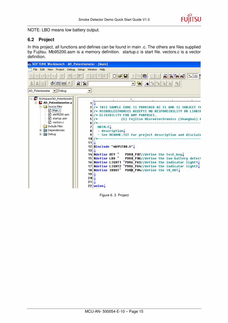
NOTE: LBO means low battery output.
6.2 Project In this project, all functions and defines can be found in main .c. The others are files supplied by Fujitsu. Mb95200.asm is a memory definition. startup.c is start file. vectors.c is a vector definition.
Figure 6. 3 Project

Smoke Detector Demo Quick Start GuideV1.0
MCU-AN- 500054-E-10 – Page 16
7 More Information
For more information on FUJITSU MB95200 products, please visit following website:
Simplified Chinese Version http://www.fujitsu.com/cn/fmc/services/mcu/mb95200/

Smoke Detector Demo Quick Start Guide V1.0
MCU-AN- 500054-E-10 – Page 17
8 Appendix
Figure 2. 1 Demo platform...................................................................................................... 5�
Figure 5. 1 System Block Diagram ......................................................................................... 8�
Figure 5. 2 Smoke Detector .................................................................................................. 9�
Figure 5. 3 MCU ................................................................................................................... 10�
Figure 5. 4 DC-DC .............................................................................................................. 11�
Figure 5. 5 Amplifier Circuit .................................................................................................. 12�
Figure 5. 6 IR Emitter .......................................................................................................... 12�
Figure 6. 1 Main Function ................................................................................................... 13�
Figure 6. 2 Watch Timer ISR ............................................................................................... 14�
Figure 6. 3 Project ............................................................................................................... 15�
Table 3. 1 Current Consumption ............................................................................................ 6�
Table 5. 1 Pin Assignment ................................................................................................... 11�