7700 series power track - access...
TRANSCRIPT
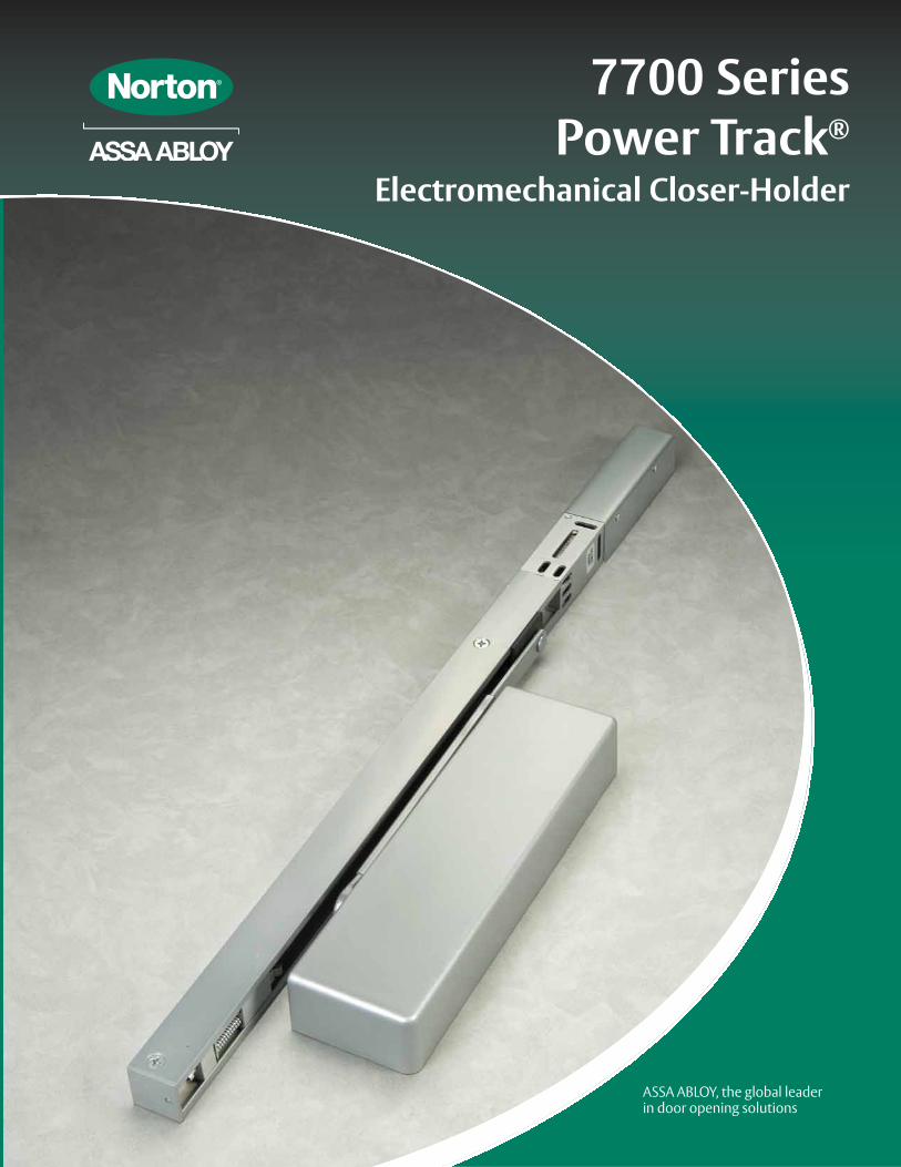
7700 SeriesPower Track®
Electromechanical Closer-Holder

Power Track®
Power Track® - 2www.nortondoorcontrols.com 12/07
INTRODUCTION
Power Track® - 2
Norton’s Power Track® Closer-Holders combine the functions of a single point electromechanical door holder with the provenreliability of a 7700 Series Door Closer. The track assembly contains an arm slide and solenoid operated hold open mechanism and isavailable with or without an integral smoke detector. The closer is mounted on the door. The Power Track and hook-up box are mountedto the frame face for pull side installations or the frame soffit for push side installations.
The Power Track is an aluminum extrusion which incorporates a solenoid actuatedcam that locks the arm slide in the track at a selected point. The degree of door holdopen is selected by adjustment of the telescoping arm. When there is power to theunit, the door will hold open at the selected hold open point. Any powerinterruption will release the arm slide and the door will close. The door can bereleased manually at any time.
Introduction & Functions . . . . . . . . . . . . . . . . . . . . . . . . . . . . . . . . . . . . . . . . . . . . . . . . . . . . . . . . . . . . . . . . . . . . . . . . . . . . . . . . . . . . . . . . . .2How To Order, Finishes, Compliance Standards . . . . . . . . . . . . . . . . . . . . . . . . . . . . . . . . . . . . . . . . . . . . . . . . . . . . . . . . . 3Overview & Features . . . . . . . . . . . . . . . . . . . . . . . . . . . . . . . . . . . . . . . . . . . . . . . . . . . . . . . . . . . . . . . . . . . . . . . . . . . . . . . . 4Ordering Power Track® Voltages . . . . . . . . . . . . . . . . . . . . . . . . . . . . . . . . . . . . . . . . . . . . . . . . . . . . . . . . . . . . . . . . . . . . . . 57705PT Technical Details . . . . . . . . . . . . . . . . . . . . . . . . . . . . . . . . . . . . . . . . . . . . . . . . . . . . . . . . . . . . . . . . . . . . . . . . . . . . . 6P7705PT Technical Details . . . . . . . . . . . . . . . . . . . . . . . . . . . . . . . . . . . . . . . . . . . . . . . . . . . . . . . . . . . . . . . . . . . . . . . . . . . .7Electrical Information, Suggested Specifications . . . . . . . . . . . . . . . . . . . . . . . . . . . . . . . . . . . . . . . . . . . . . . . . . . . . . . . . . . . . . . . . . . .8Track Assemblies . . . . . . . . . . . . . . . . . . . . . . . . . . . . . . . . . . . . . . . . . . . . . . . . . . . . . . . . . . . . . . . . . . . . . . . . . . . . . . . . . . . . 9Parts . . . . . . . . . . . . . . . . . . . . . . . . . . . . . . . . . . . . . . . . . . . . . . . . . . . . . . . . . . . . . . . . . . . . . . . . . . . . . . . . . . . . . . . . . . . . . 10Notes . . . . . . . . . . . . . . . . . . . . . . . . . . . . . . . . . . . . . . . . . . . . . . . . . . . . . . . . . . . . . . . . . . . . . . . . . . . . . . . . . . . . . . . . . . . . 11
Master Unit• Unit comprised of integral smoke
detector and solenoid hold openmechanism in the slide track, ahook-up box and door closer.
• Can be used to control a singledoor or a pair of doors in conjunction with either a SlaveUnit or a 24VDC Support Unit.
• Suffix “PTD” to model number.
Slave Unit• Unit is for installation on one leaf
of a pair of doors when the otherleaf is controlled by a “PTD” MasterUnit.
• The unit is composed of a solenoidhold open mechanism in the slidetrack, hook-up box and a doorcloser.
• Unit will only operate on 24VDCpower from the Master unit.
• Suffix “PTS” to model number.
Support Unit• Unit is comprised of a solenoid
hold open mechanism in the slidetrack, hook-up box and a doorcloser.
• Units can be installed on a singledoor or a pair of doors whencontrolled by compatible UL listeddetection equipment such as areaceiling detectors, pull stations, andremote alarm panels.
• A 24VDC Support Unit can alsoserve as a slave unit when used onthe inactive leaf of a pair of doors.The active leaf of the pair of doorsmust be controlled by a MasterUnit.
• Suffix “PT” to model number.
FUNCTIONS
TABLE OFCONTENTS

*600 is a special rust inhibiting prime coat. Closers can be ordered prime coat only (specify closer x 600). An additional charge appliesif finish coat is required over prime coat (ex: 7705PT x 600 x 689).
Finishes other than those listed above may be available on special order. Sample chips will be required.
HOW TOORDER
Power Track®
Power Track® - 3www.nortondoorcontrols.com12/07
FINISH
Power Track® - 3
Product will be painted with acombination of waterborne acrylicand polyester powder coat.
Sprayed Finishes
Description Specify Designation
Complements the following finishes
OldDesignation
Aluminum 689 628, 625, 629, 630, 651, 652 AL
Statuary Bronze 690 640, 613, 695 STAT
Dull Bronze 691 612, 637, 639 DB
Black 693 315 315
Medium Amber 694 312 312
Gold 696 605, 606, 632, 633 GB
Prime Coat (Beige)* 600 SRI
None – Unit mounted on pull (hinge) side of door. Maximum reveal 1/8" (3mm) For greater reveals up to 3" (76mm) suffix “DE” to model number
P – Unit mounted on push (stop) side of door
PTD - Master Unit with Integral Smoke Detector
PTS - Slave Unit (24 volts only). Onlyused with a Master Unit
PT - Support Unit (used with area/ceiling detectors)
DE - Deep Reveal Arm for DoubleEgress Frames (specify hand). Reveals 1/8" – 3" (3-76mm). Hinge (pull) side units only.
7705 – 7700 Series Door Closer
Refer to chart below
PPREFIX
VOLTAGEPTDSUFFIXES
7705DOOR CLOSER
Power Track® is ANSI/BHMA A156.15 certified. Power Track is listed by Underwriters Laboratories for labeled fire doors. Theproduct is manufactured in an ISO 9001 facility.
California State Fire Marshal Listings: 03550-0257:100, 03550-0257:101
X X
FINISHES
COMPLIANCESTANDARDS

Selective Single-Point Hold Open:The Power Track® has one templateposition. The single-point hold openposition is selected by adjusting thetelescoping arm with a hex drive set screw.Hold open range is 85° thru 110° inapproximately 3° increments.
Non-Handed:Units are non-handed except whenordered with "DE" Double Egress arms.
Choice of Push or Pull Side Installation:No prefix indicates pull side application.Prefix “P” for push side installation.
Choice of Supply
Voltage:Available in 24VAC/DC or 120VAC, 60Hz.voltages. Power to these devices must bewithin a range of (+) 10% (-) 15% of thestated voltage.
Fail Safe:In the event of a power outage, the PowerTrack solenoid will be de-energized and thecloser/holder will then operate as a normaldoor closer.
Wiring Option:Both pull and push side applications willaccommodate either concealed or surfacewiring. The hook-up box will accept 3/4"(19mm) conduit. Each Power Track issupplied with a thin-walled conduit nut toattach the conduit clamp. The hook-up boxcover must be prepared for surface wiringusing a knockout punch or electrical tradehole cutter. State and local building codeswill dictate the type of wiring.
Spring Cushioned Dead Stop:A spring-loaded buffer block at the point ofhold open prevents over travel of the armslide and provides a cushioned dead stop.Use of an additional wall or floor stop isalways recommended.
OVERVIEW
Power Track®
Power Track® - 4www.nortondoorcontrols.com 12/07
Power Track® - 4
Spring CushionedDead Stop
Hold OpenSolenoid and
Roller AssemblySlide Track
Green LEDPilot Light
SmokeDetector
Hook-Up Board CoverRed LED Alarm Light
TelescopingArm
STANDARDFEATURES
FEATURES - SMOKE
DETECTOR
Dual Chamber Ionization SensingDetector employs dual ionization chambers to substantiallyreduce the probability of false alarms.Fire/Smoke Control CircuitInterprets the alarm signal from the detector and providesswitching contacts to interrupt power to the hold open solenoidand divert it to activate optional audio/visual alarms.Alarm (Relay) ContactsNormally open in standby condition (energized, non-alarm state).These contacts close during an alarm condition (smoke detected)and switch power from the solenoid to an optional local alarm.Trouble (Relay) ContactsNormally closed in standby condition, these supervisory contactsmonitor the continuity of power within the detector circuit. Anypower interruption within the detector circuit will open thesecontacts. They can then be used to simultaneously indicate atrouble condition to the alarm panel on a separate trouble circuit.
Quick Disconnect ModulesEach component, solenoid coil, detector and control feature quickdisconnect wiring for easy servicing and replacement.Locked-In AlarmWhen a unit alarms, it must be manually reset. This can beaccomplished by remote control from the alarm console or by thereset button in the smoke detector. Reset button is accessiblethrough a hole in the underside of the track.Alarm LightA red LED is illuminated when the detector goes into the alarmcondition (smoke detected). This light is easily visible from theunderside of the track, which makes an alarmed unit easy to identify.Pilot LightA green LED easily visible from the underside of the track isilluminated at all times except when a Trouble Condition is sensed.Indicates at a glance whether or not the unit is energized.
Slide Assembly Hook-UpBoard

Power Track®
Power Track® - 5www.nortondoorcontrols.com12/07
ORDERINGVOLTAGES
Power Track® - 5
“PTD” Master Units• Two components require electrical power:
- Integral smoke detector requires 24VDC input power.- Hold open solenoid requires 24VDC input.
• Hook-up box receives primary voltage input and distributes itto the smoke detector and hold open solenoid(s).
• Available with two voltage options:- PTD-24 suffix –
- Accepts 24VAC or 24VDC power input. - A rectifier in the hook-up box will rectify alternating
current to direct current for operation of both the smoke detector and hold open solenoid(s).
- PTD-120 suffix –- Accepts 120VAC power input. - A 120VAC to 24VAC transformer in the hook-up box steps
the input voltage down to 24VAC. It is then rectified to24VDC for operation of both the smoke detector and the24VDC hold open solenoid(s).
“PTS” Slave Units• Hold open solenoid requires electrical power from master unit.• Only available 24VDC.• Only installed when controlled directly by the integral smoke
detector of the Master Unit. “PT” Support Units • Hold open solenoid requires electrical power.• Solenoid controlled by smoke detection equipment (ceiling
detectors) or remote alarm panels.• Available for operation on 24VAC/DC or 120VAC, 60Hz.• Hold open solenoid operates on direct current.• Contains built-in rectifier that converts alternating current
to direct current.
Type of Unit Model# of PowerInput Lines
Choices of Voltage Input Can be used with
Master
PTD-24
1
24 VAC/DCSlave Model PTS
or 24V Support Model PT
PTD-120 120 VAC, 60 HzSlave Model PTS
or 24V Support Model PT
Slave PTS 1 Power Supplied from Master Unit(24VDC) Master Model PTD-24 or PTD-120
Support
PT-24
1
24 VAC/DC
Area Smoke Detection System
PT-120 120 VAC, 60Hz
Operating voltage for the control of fire/smoke doors are specified by the architect, electrical engineer and alarm system engineerand/or contractor. Consulting with these sources will verify which operating voltage should be ordered.

www.nortondoorcontrols.com
7705POWER TRACK®
Power Track®
Power Track® - 612/07
Power Track® - 6
Model # Description
7705PTD Master Unit Controlled by Integral Smoke Detector
7705PTS Slave Unit Controlled by Master Unit SmokeDetector
7705PT Support Unit Controlled by Remote DetectionEquipment
13-5/8(346)
32-3/16(818)
3-1/8(79)CL Support or Slave Unit
35-13/16(910)
3-1/8(79)CL
Master Unit
1-1/2(38)
4-1/2(114)
3-1/2(89)
1-1/2(38)
2-1/8(54)
3-7/8(98)
2-1/8(54)
4-1/8(105)
2-1/8" (54mm) minimum ceiling clearancerequired for Power Track.
* Maximum door size for door closer power.** Minimum door opening for standard
installation. Consult factory for door openings narrower than those shown.
Double Egress Doors: With reveals greater than 1/8" (3mm); a special handed arm for thepull (hinge) side Power Track is available.Accommodates reveals to 3" (76mm). Suffix“DE” to model number; specify hand.
Door(s) Opening Inches (cm) Model Number & TypeMax.* Min.**
Single Door48" (122) 36" (91) (1) 7705PTD Master Unit48" (122) 32" (81) (1) 7705PT Support Unit
Pairs of Doors
96" (244) 68" (173)(1) 7705PTD Master Unit and
(1) 7705PTS Slave Unit or(1) 7705PT Support Unit
96" (244) 64-1/2" (164)(2) 7705PT Support Units
(controlled by remote detection equipment)
Minimum Top Rail
Without Drop Plate
With 7786 Drop Plate
3-1/2" (89mm)
1-7/8" (48mm)
7705PTD Shown
PULL (HINGE) SIDE MOUNTING
TECHNICALDETAILS
DOOR SIZE
P7705POWER TRACK®
Power Track®
Power Track® - 7www.nortondoorcontrols.com12/07
DOOR SIZE
Power Track® - 7
P7705PT Shown
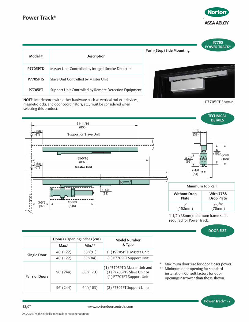
Model # Description
P7705PTD Master Unit Controlled by Integral Smoke Detector
P7705PTS Slave Unit Controlled by Master Unit
P7705PT Support Unit Controlled by Remote Detection Equipment
NOTE: Interference with other hardware such as vertical rod exit devices,magnetic locks, and door coordinators, etc., must be considered whenselecting this product.
31-11/16(805)
2-5/8(67)CL Support or Slave Unit
35-5/16(897)
CL Master Unit
1-1/2(38)
13-5/8(346)
3-5/8(92)
2-5/8(67)
1-1/2(38)
2-1/8(54)
3-7/8(98)
6(152) 6-5/8
(168)
Door(s) Opening Inches (cm) Model Number & TypeMax.* Min.**
Single Door48" (122) 36" (91) (1) P7705PTD Master Unit
48" (122) 33" (84) (1) P7705PT Support Unit
Pairs of Doors96" (244) 68" (173)
(1) P7705PTD Master Unit and (1) P7705PTS Slave Unit or(1) P7705PT Support Unit
96" (244) 64" (163) (2) P7705PT Support Units
* Maximum door size for door closer power.** Minimum door opening for standard
installation. Consult factory for door openings narrower than those shown.
Push (Stop) Side Mounting
TECHNICALDETAILS
Minimum Top Rail
Without DropPlate
With 7788Drop Plate
6"(152mm)
2-3/4"(70mm)
1-1/2" (38mm) minimum frame soffitrequired for Power Track.
ELECTRICALINFORMATION
Power Track®
Power Track® - 8www.nortondoorcontrols.com 12/07
Closers for ______ doors shall be electromechanical closer-holder. Hold open to be achieved by electric solenoid locking ofcloser arm slide in its track. Track, arm, slide (and) solenoid (andintegral smoke detector) to be contained in a single aluminumextrusion 1-1/2" (38mm) high, 1-1/2" (38mm) deep.
Closer shall be door mounted. Track and hold open mechanismshall be surface mounted to the frame face for application on thepull side of the door and frame soffit mounted for application onthe push side of the door. Single point hold open shall beselective through a range of 85° to 110°. Hold open point to beachieved by adjustment of a telescoping closer arm.
Closer shall be hydraulic with full rack and pinion enclosed in acast aluminum alloy shell. Hydraulic fluid shall be non-gummingand non-freezing. Closer shall have two non-critical valves toindependently regulate sweep speed and latch speed. It shallhave an adjustable backcheck cushioning valve and an adjustablebackcheck positioning valve. All valves shall be adjustable with ahex-key. (Closer shall have spring power adjustment to permit50% increase in closing power.) Closer to be enclosed in amolded full cover.
(Master units to have an integral smoke detector with dual ionization chamber. Master units integral smoke detector shallhave latching alarm and reset switch.) (Slave units to becontrolled by the master unit.) (Support units to be controlledby U.L. Listed Smoke Detection Equipment.) Units to be fail safeand close the door during an interruption to the electrical power.The hold open solenoid coil shall have a maximum amperagedraw of (.090 Amps at 24 volts) (.018 Amps at 120 volts). Unitshall have a switch to permit testing of the releasing devicefunction without alarming the system.
All wiring connections shall be made without the need of wirenuts or soldering. Master unit(s) shall require a (24VAC/DC)(120VAC, 60Hz) power input. Slave unit(s) shall require a 24 voltpower input from the Master Unit. Support unit(s) shall require a(24VAC/DC) (120, 60Hz) power input. Supplier to coordinateelectrical requirements with electrical and alarm systemengineers. Wiring (and conduit) by others. ElectromechanicalCloser-Holder to be Norton® Power Track® [(P)7700(PT)(PTD)(PTS)].
SUGGESTEDSPECIFICATIONS
Power Track® - 8
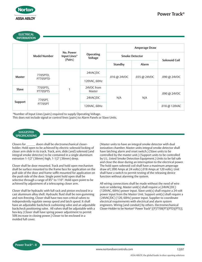
Model NumberNo. Power
Input Lines*(Pairs)
OperatingVoltage
Amperage Draw
Smoke DetectorSolenoid Coil
Standby Alarm
Master 7705PTD, P7705PTD
1
24VAC/DC.016 @ 24VDC .035 @ 24VDC .090 @ 24VDC
120VAC, 60Hz
Slave 7705PTS,P7705PTS
24VDC from Master
N/A N/A.090 @ 24VDC
Support7705PT, P7705PT
24VAC/DC
120VAC, 60Hz .018 @ 120VAC
*Number of Input Lines (pairs) required to supply Operating Voltage. This does not include signal or control lines (pairs) to Alarm Panels or Slave Units.

TRACKASSEMBLIES
Power Track®
Power Track® - 9www.nortondoorcontrols.com12/07
Power Track® - 9
Description VoltagePart Number
Hinge Side Stop Side
Master Unit 24V or 120V PTD24/120 PPTD24/120
Support Unit 120V PT120 PPT120
Support or Slave Unit 24V PT24 PPT24
Buffer Spring
Stationary BlockAssembly
CushionBlock
RollerAssembly
SlideAssembly7700SLD
Slide Track Assembly(See Chart)
Arm Stud Clip7700ASC
(Included when7700SLD is
ordered)
NOTE: Mounting hardware included with all parts orders.
Solenoid Block Assembly
Voltage Part Number24V PT24SOL
120V PT120SOL
Description VoltagePart Number
Hook-Up Board Hook-Up Box Smoke Detector Board
Master Unit24V PTDPCB24 PTDHB24
PTSD24120V PTDPCB120 PTDHB120
Support24V PTPCB24 PTHB24
N/A120V PTPCB120 PTHB120
Slave 24V PTSPCB24 PTSHB24
Master Unit Track Assemblies include track, slider assembly, solenoid block assembly and detector. Hook-up box not included.Support and Slave Unit Track Assemblies include track, slider assembly and solenoid block assembly. Hook-up box not included.
Spring Plate
End Cap7700STEC
Roll PinSolenoid BlockAssembly (includesRoller Assembly)
PARTS
Power Track®
Power Track® - 10www.nortondoorcontrols.com 12/07
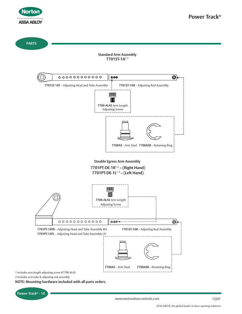
7701ST-1AT – Adjusting Head and Tube Assembly 7701ST-1AR – Adjusting Rod Assembly
7700-ALAS Arm LengthAdjusting Screw
7700AS – Arm Stud 7700ASR – Retaining Ring
7700-ALAS Arm LengthAdjusting Screw
7700AS – Arm Stud 7700ASR – Retaining Ring
7701PT-1ATR – Adjusting Head and Tube Assembly RH7701PT-1ATL – Adjusting Head and Tube Assembly LH
1 Includes arm length adjusting screw #7700-ALAS
2 Includes arm tube & adjusting rod assembly
7701PT-DE-1R1, 2 – (Right Hand)7701PT-DE-1L1, 2 – (Left Hand)
7701ST-1AR – Adjusting Rod Assembly
Power Track® - 10
Standard Arm Assembly 7701ST-1A1, 2
Double Egress Arm Assembly
NOTE: Mounting hardware included with all parts orders.
NOTES
Power Track®
Power Track® - 11www.nortondoorcontrols.com12/07
Power Track® - 11
43033-12/07R
For a complete listing of products andapplications please visit our web site.
www.nortondoorcontrols.comwww.assaabloydsscanada.ca
Or contact us at:
Norton® and Power Track® are registered trademarks of therespective ASSA ABLOY Group company. Other products' brandnames may be trademarks or registered trademarks of theirrespective owners and are mentioned for reference purposesonly. These materials are protected under U.S. copyright laws.All contents current at time of publication. Copyright © 2002,2007, ASSA ABLOY Group companies. All rights reserved.
Norton Door Controls3000 Highway 74 East
Monroe, NC 28112Tel: 1-877-974-2255Fax: 1-800-338-0965
ASSA ABLOY Door Security Solutions Canada160 Four Valley Drive
Vaughan, Ontario, Canada L4K 4T9Tel: 1-800-461-3007