74lv4051 8-channel analog multiplexer/demultiplexer file1. general description the 74lv4051 is an...
TRANSCRIPT

1. General description
The 74LV4051 is an 8-channel analog multiplexer/demultiplexer with three digital selectinputs (S0 to S2), an active-LOW enable input (E), eight independent inputs/outputs (Y0 toY7) and a common input/output (Z). It is a low-voltage Si-gate CMOS device that is pinand function compatible with 74HC4051 and 74HCT4051. With E LOW, one of the eightswitches is selected (low impedance ON-state) by S0 to S2. With E HIGH, all switches arein the high-impedance OFF-state, independent of S0 to S2.
VCC and GND are the supply voltage pins for the digital control inputs (S0 to S2, and E).The VCC to GND ranges are 1.0 V to 6.0 V. The analog inputs/outputs (Y0 to Y7, and Z)can swing between VCC as a positive limit and VEE as a negative limit. VCC − VEE may notexceed 6.0 V. For operation as a digital multiplexer/demultiplexer, VEE is connected toGND (typically ground).
2. Features
n Optimized for low-voltage applications: 1.0 V to 6.0 V
n Accepts TTL input levels between VCC = 2.7 V and VCC = 3.6 V
n Low ON resistance:
u 145 Ω (typical) at VCC − VEE = 2.0 V
u 80 Ω (typical) at VCC − VEE = 3.0 V
u 60 Ω (typical) at VCC − VEE = 4.5 V
n Logic level translation:
u To enable 3 V logic to communicate with ±3 V analog signals
n Typical ‘break before make’ built in
n ESD protection:
u HBM JESD22-A114E exceeds 2000 V
u MM JESD22-A115-A exceeds 200 V
n Multiple package options
n Specified from −40 °C to +85 °C and from −40 °C to +125 °C
74LV40518-channel analog multiplexer/demultiplexerRev. 04 — 10 August 2009 Product data sheet

NXP Semiconductors 74LV40518-channel analog multiplexer/demultiplexer
3. Ordering information
4. Functional diagram
Table 1. Ordering information
Type number Package
Temperature range Name Description Version
74LV4051N −40 °C to +125 °C DIP16 plastic dual in-line package; 16 leads (300 mil) SOT38-4
74LV4051D −40 °C to +125 °C SO16 plastic small outline package; 16 leads;body width 3.9 mm
SOT109-1
74LV4051DB −40 °C to +125 °C SSOP16 plastic shrink small outline package; 16 leads;body width 5.3 mm
SOT338-1
74LV4051PW −40 °C to +125 °C TSSOP16 plastic thin shrink small outline package; 16 leads;body width 4.4 mm
SOT403-1
74LV4051BQ −40 °C to +125 °C DHVQFN16 plastic dual in-line compatible thermal enhanced verythin quad flat package; no leads; 16 terminals;body 2.5 × 3.5 × 0.85 mm
SOT763-1
Fig 1. Functional diagram
001aad543
LOGICLEVEL
CONVERSION
11
16
VCC
13 Y0
S0
1-OF-8DECODER
14 Y1
15 Y2
12 Y3
1 Y4
5 Y5
2 Y6
4 Y7
3 Z
10S1
9S2
6
8 7
GND VEE
E
74LV4051_4 © NXP B.V. 2009. All rights reserved.
Product data sheet Rev. 04 — 10 August 2009 2 of 26

NXP Semiconductors 74LV40518-channel analog multiplexer/demultiplexer
Fig 2. Logic symbol Fig 3. IEC logic symbol
001aad541
13Y0
1411Y1S0
10S1
9S2
6E
15Y2
12Y3
1Y4
5Y5
Z
3
2Y6
4Y7
2
0
MUX/DMUX13
G8
14
15
123
1
5
2
4
0
1
2
3
4
5
6
7
001aad542
8 X07
11109
6
Fig 4. Schematic diagram (one switch)
001aad544
fromlogic
VCC
VEE
VEE
VCC
VCC
VEE
Y
Z
VCC
74LV4051_4 © NXP B.V. 2009. All rights reserved.
Product data sheet Rev. 04 — 10 August 2009 3 of 26

NXP Semiconductors 74LV40518-channel analog multiplexer/demultiplexer
5. Pinning information
5.1 Pinning
5.2 Pin description
Fig 5. Pin configuration SOT38-4and SOT109-1
Fig 6. Pin configurationSOT338-1 and SOT403-1
Fig 7. Pin configuration forSOT763-1
74LV4051
Y4 VCC
Y6 Y2
Z Y1
Y7 Y0
Y5 Y3
E S0
VEE S1
GND S2
001aak433
1
2
3
4
5
6
7
8
10
9
12
11
14
13
16
15 74LV4051
Y4 VCC
Y6 Y2
Z Y1
Y7 Y0
Y5 Y3
E S0
VEE S1
GND S2
001aak407
1
2
3
4
5
6
7
8
10
9
12
11
14
13
16
15
001aak408
74LV4051
VEE S1
E S0
Y5 Y3
Y7 Y0
Z Y1
Y6 Y2
GN
D S2
Y4
VC
C
Transparent top view
7 10
6 11
5 12
4 13
3 14
2 15
8 9
1 16
terminal 1index area
VCC(1)
Table 2. Pin description
Symbol Pin Description
E 6 enable input (active LOW)
VEE 7 supply voltage
GND 8 ground supply voltage
S0, S1, S2 11, 10, 9 select input
Y0, Y1, Y2, Y3, Y4, Y5, Y6, Y7 13, 14, 15, 12, 1, 5, 2, 4 independent input or output
Z 3 common output or input
VCC 16 supply voltage
74LV4051_4 © NXP B.V. 2009. All rights reserved.
Product data sheet Rev. 04 — 10 August 2009 4 of 26

NXP Semiconductors 74LV40518-channel analog multiplexer/demultiplexer
6. Functional description
6.1 Function table
[1] H = HIGH voltage level;
L = LOW voltage level;
X = don’t care.
7. Limiting values
[1] To avoid drawing VCC current out of terminal Z, when switch current flows into terminals Yn, the voltage drop across the bidirectionalswitch must not exceed 0.4 V. If the switch current flows into terminal Z, no VCC current will flow out of terminals Yn, and in this casethere is no limit for the voltage drop across the switch, but the voltages at Yn and Z may not exceed VCC or VEE.
[2] The minimum input voltage rating may be exceeded if the input current rating is observed.
[3] For DIP16 packages: above 70 °C the value of Ptot derates linearly with 12 mW/K.
For SO16 packages: above 70 °C the value of Ptot derates linearly with 8 mW/K.
For SSOP16 and TSSOP16 packages: above 60 °C the value of Ptot derates linearly with 5.5 mW/K.
For DHVQFN16 packages: above 60 °C the value of Ptot derates linearly with 4.5 mW/K.
Table 3. Function table [1]
Input Channel ON
E S2 S1 S0
L L L L Y0 to Z
L L L H Y1 to Z
L L H L Y2 to Z
L L H H Y3 to Z
L H L L Y4 to Z
L H L H Y5 to Z
L H H L Y6 to Z
L H H H Y7 to Z
H X X X switches off
Table 4. Limiting valuesIn accordance with the Absolute Maximum Rating System (IEC 60134). Voltages are referenced to VSS = 0 V (ground).
Symbol Parameter Conditions Min Max Unit
VCC supply voltage [1] −0.5 +7.0 V
IIK input clamping current VI < −0.5 V or VI > VCC + 0.5 V [2] - ±20 mA
ISK switch clamping current VSW < −0.5 V or VSW > VCC + 0.5 V [2] - ±20 mA
ISW switch current VSW > −0.5 V or VSW < VCC + 0.5 V;source or sink current
[2] - ±25 mA
Tstg storage temperature −65 +150 °C
Ptot total power dissipation Tamb = −40 °C to +125 °C [3]
DIP16 package - 750 mW
SO16 package - 500 mW
TSSOP16 package - 500 mW
DHVQFN16 package - 500 mW
74LV4051_4 © NXP B.V. 2009. All rights reserved.
Product data sheet Rev. 04 — 10 August 2009 5 of 26

NXP Semiconductors 74LV40518-channel analog multiplexer/demultiplexer
8. Recommended operating conditions
[1] The static characteristics are guaranteed from VCC = 1.2 V to 6.0 V, but LV devices are guaranteed to function down to VCC = 1.0 V (withinput levels GND or VCC).
Table 5. Recommended operating conditions [1]
Symbol Parameter Conditions Min Typ Max Unit
VCC supply voltage see Figure 8 1 3.3 6 V
VI input voltage 0 - VCC V
VSW switch voltage 0 - VCC V
Tamb ambient temperature in free air −40 - +125 °C
∆t/∆V input transition rise and fall rate VCC = 1.0 V to 2.0 V - - 500 ns/V
VCC = 2.0 V to 2.7 V - - 200 ns/V
VCC = 2.7 V to 3.6 V - - 100 ns/V
Fig 8. Guaranteed operating area as a function of the supply voltages
VCC - VEE (V)0 8.06.02.0 4.0
001aak344
4.0
2.0
6.0
8.0
VCC - GND(V)
0
operating area
74LV4051_4 © NXP B.V. 2009. All rights reserved.
Product data sheet Rev. 04 — 10 August 2009 6 of 26

NXP Semiconductors 74LV40518-channel analog multiplexer/demultiplexer
9. Static characteristics
[1] Typical values are measured at Tamb = 25 °C.
Table 6. Static characteristicsAt recommended operating conditions. Voltages are referenced to GND (ground = 0 V).
Symbol Parameter Conditions −40 °C to +85 °C −40 °C to +125 °C Unit
Min Typ[1] Max Min Max
VIH HIGH-level input voltage VCC = 1.2 V 0.9 - - 0.9 - V
VCC = 2.0 V 1.4 - - 1.4 - V
VCC = 2.7 V to 3.6 V 2.0 - - 2.0 - V
VCC = 4.5 V 3.15 - - 3.15 - V
VCC = 6.0 V 4.20 - - 4.20 - V
VIL LOW-level input voltage VCC = 1.2 V - - 0.3 - 0.3 V
VCC = 2.0 V - - 0.6 - 0.6 V
VCC = 2.7 V to 3.6 V - - 0.8 - 0.8 V
VCC = 4.5 V - - 1.35 - 1.35 V
VCC = 6.0 V - - 1.80 - 1.80 V
II input leakage current VI = VCC or GND
VCC = 3.6 V - - 1.0 - 1.0 µA
VCC = 6.0 V - - 2.0 - 2.0 µA
IS(OFF) OFF-state leakage current VI = VIH or VIL; see Figure 9
VCC = 3.6 V - - 1.0 - 1.0 µA
VCC = 6.0 V - - 2.0 - 2.0 µA
IS(ON) ON-state leakage current VI = VIH or VIL; see Figure 10
VCC = 3.6 V - - 1.0 - 1.0 µA
VCC = 6.0 V - - 2.0 - 2.0 µA
ICC supply current VI = VCC or GND; IO = 0 A
VCC = 3.6 V - - 20 - 40 µA
VCC = 6.0 V - - 40 - 80 µA
∆ICC additional supply current per input; VI = VCC − 0.6 V;VCC = 2.7 V to 3.6 V
- - 500 - 850 µA
CI input capacitance - 3.5 - - - pF
Csw switch capacitance independent pins Yn - 5 - - - pF
common pin Z - 25 - - - pF
74LV4051_4 © NXP B.V. 2009. All rights reserved.
Product data sheet Rev. 04 — 10 August 2009 7 of 26

NXP Semiconductors 74LV40518-channel analog multiplexer/demultiplexer
9.1 Test circuits
9.2 ON resistance
VI = VCC or VEE and VO = VEE or VCC. VI = VCC or VEE and VO = open circuit.
Fig 9. Test circuit for measuring OFF-state leakagecurrent
Fig 10. Test circuit for measuring ON-state leakagecurrent
IS IS
001aak409
VCC
VI
GND = VEE
S0 to S2
E
Z
VIH or VIL
VCC
Yn
VO
IS
001aak410
GND
VO
GND = VEE
S0 to S2
E
Z
VIH or VIL
VCC
Yn
VI
Table 7. ON resistanceAt recommended operating conditions; voltages are referenced to GND (ground = 0 V); for graphs see Figure 11 andFigure 12.
Symbol Parameter Conditions −40 °C to +85 °C −40 °C to +125 °C Unit
Min Typ[1] Max Min Max
RON(peak) ON resistance (peak) VI = 0 V to VCC − VEE
VCC = 1.2 V; ISW = 100 µA [2] - - - - - Ω
VCC = 2.0 V; ISW = 1000 µA - 145 325 - 375 Ω
VCC = 2.7 V; ISW = 1000 µA - 90 200 - 235 Ω
VCC = 3.0 V to 3.6 V;ISW = 1000 µA
- 80 180 - 210 Ω
VCC = 4.5 V; ISW = 1000 µA - 60 135 - 160 Ω
VCC = 6.0 V; ISW = 1000 µA - 55 125 - 145 Ω
∆RON ON resistance mismatchbetween channels
VI = 0 V to VCC − VEE
VCC = 1.2 V; ISW = 100 µA [2] - - - - - Ω
VCC = 2.0 V; ISW = 1000 µA - 5 - - - Ω
VCC = 2.7 V; ISW = 1000 µA - 4 - - - Ω
VCC = 3.0 V to 3.6 V;ISW = 1000 µA
- 4 - - - Ω
VCC = 4.5 V; ISW = 1000 µA - 3 - - - Ω
VCC = 6.0 V; ISW = 1000 µA - 2 - - - Ω
74LV4051_4 © NXP B.V. 2009. All rights reserved.
Product data sheet Rev. 04 — 10 August 2009 8 of 26

NXP Semiconductors 74LV40518-channel analog multiplexer/demultiplexer
[1] Typical values are measured at Tamb = 25 °C.
[2] When supply voltages (VCC − VEE) near 1.2 V the analog switch ON resistance becomes extremely non-linear. When using a supply of1.2 V, it is recommended to use these devices only for transmitting digital signals.
RON(rail) ON resistance (rail) VI = GND
VCC = 1.2 V; ISW = 100 µA [2] - 225 - - - Ω
VCC = 2.0 V; ISW = 1000 µA - 110 235 - 270 Ω
VCC = 2.7 V; ISW = 1000 µA - 70 145 - 165 Ω
VCC = 3.0 V to 3.6 V;ISW = 1000 µA
- 60 130 - 150 Ω
VCC = 4.5 V; ISW = 1000 µA - 45 100 - 115 Ω
VCC = 6.0 V; ISW = 1000 µA - 40 85 - 100 Ω
RON(rail) ON resistance (rail) VI = VCC − VEE
VCC = 1.2 V; ISW = 100 µA [2] - 250 - - - Ω
VCC = 2.0 V; ISW = 1000 µA - 120 320 - 370 Ω
VCC = 2.7 V; ISW = 1000 µA - 75 195 - 225 Ω
VCC = 3.0 V to 3.6 V;ISW = 1000 µA
- 70 175 - 205 Ω
VCC = 4.5 V; ISW = 1000 µA - 50 130 - 150 Ω
VCC = 6.0 V; ISW = 1000 µA - 45 120 - 135 Ω
Table 7. ON resistance …continuedAt recommended operating conditions; voltages are referenced to GND (ground = 0 V); for graphs see Figure 11 andFigure 12.
Symbol Parameter Conditions −40 °C to +85 °C −40 °C to +125 °C Unit
Min Typ[1] Max Min Max
74LV4051_4 © NXP B.V. 2009. All rights reserved.
Product data sheet Rev. 04 — 10 August 2009 9 of 26

NXP Semiconductors 74LV40518-channel analog multiplexer/demultiplexer
9.3 On resistance waveform and test circuit
RON = VSW / ISW.
Fig 11. Test circuit for measuring R ON
V
001aak411
GND
VI
VSW
ISW
GND = VEE
S0 to S2
E
Z
VIH or VIL
VCC
Yn
Vi = 0 V to VCC − VEE
Fig 12. Typical R ON as a function of input voltage
001aak412
VI (V)0 4.81.2 2.4 3.6
120
60
180
RON(Ω)
0
VCC = 2.0 V
VCC = 3.0 V
VCC = 4.5 V
74LV4051_4 © NXP B.V. 2009. All rights reserved.
Product data sheet Rev. 04 — 10 August 2009 10 of 26

NXP Semiconductors 74LV40518-channel analog multiplexer/demultiplexer
10. Dynamic characteristics
Table 8. Dynamic characteristicsVoltages are referenced to GND (ground = 0 V). For test circuit see Figure 15.
Symbol Parameter Conditions −40 °C to +85 °C −40 °C to +125 °C Unit
Min Typ[1] Max Min Max
tpd propagation delay Yn to Z, Z to Yn; see Figure 13 [2]
VCC = 1.2 V - 25 - - - ns
VCC = 2.0 V - 9 17 - 20 ns
VCC = 2.7 V - 6 13 - 15 ns
VCC = 3.0 V to 3.6 V [3] - 5 10 - 12 ns
VCC = 4.5 V - 4 9 - 10 ns
VCC = 6.0 V - 3 8 - 8 ns
ten enable time E to Yn, Z; see Figure 14 [2]
VCC = 1.2 V - 145 - - - ns
VCC = 2.0 V - 49 94 - 112 ns
VCC = 2.7 V - 36 69 - 83 ns
VCC = 3.0 V to 3.6 V; CL = 15 pF [3] - 23 - - - ns
VCC = 3.0 V to 3.6 V [3] - 28 55 - 66 ns
VCC = 4.5 V - 25 47 - 56 ns
VCC = 6.0 V - 19 38 - 43 ns
Sn to Yn; see Figure 14 [2]
VCC = 1.2 V - 140 - - - ns
VCC = 2.0 V - 48 90 - 107 ns
VCC = 2.7 V - 35 66 - 79 ns
VCC = 3.0 V to 3.6 V; CL = 15 pF [3] - 22 - - - ns
VCC = 3.0 V to 3.6 V [3] - 27 53 - 63 ns
VCC = 4.5 V - 24 45 - 54 ns
VCC = 6.0 V - 18 34 - 41 ns
74LV4051_4 © NXP B.V. 2009. All rights reserved.
Product data sheet Rev. 04 — 10 August 2009 11 of 26

NXP Semiconductors 74LV40518-channel analog multiplexer/demultiplexer
[1] All typical values are measured at Tamb = 25 °C.
[2] tpd is the same as tPLH and tPHL.
ten is the same as tPZL and tPZH.
tdis is the same as tPLZ and tPHZ.
[3] Typical values are measured at nominal supply voltage (VCC = 3.3 V).
[4] CPD is used to determine the dynamic power dissipation (PD in µW).
PD = CPD × VCC2 × fi × N + Σ((CL + CSW) × VCC
2 × fo) where:
fi = input frequency in MHz, fo = output frequency in MHz
CL = output load capacitance in pF
CSW = maximum switch capacitance in pF;
VCC = supply voltage in Volts
N = number of inputs switching
Σ(CL × VCC2 × fo) = sum of the outputs.
tdis disable time E to Yn, Z; see Figure 14 [2]
VCC = 1.2 V - 145 - - - ns
VCC = 2.0 V - 51 93 - 110 ns
VCC = 2.7 V - 38 69 - 82 ns
VCC = 3.0 V to 3.6 V; CL = 15 pF [3] - 25 - - - ns
VCC = 3.0 V to 3.6 V [3] - 30 56 - 66 ns
VCC = 4.5 V - 29 48 - 56 ns
VCC = 6.0 V - 21 37 - 44 ns
Sn to Yn; see Figure 14 [2]
VCC = 1.2 V - 115 - - - ns
VCC = 2.0 V - 41 73 - 90 ns
VCC = 2.7 V - 31 54 - 67 ns
VCC = 3.0 V to 3.6 V; CL = 15 pF [3] - 20 - - - ns
VCC = 3.0 V to 3.6 V [3] - 24 44 - 54 ns
VCC = 4.5 V - 22 37 - 46 ns
VCC = 6.0 V - 17 29 - 36 ns
CPD power dissipationcapacitance
CL = 50 pF; fi = 1 MHz;VI = GND to VCC
[4] - 25 - - - pF
Table 8. Dynamic characteristics …continuedVoltages are referenced to GND (ground = 0 V). For test circuit see Figure 15.
Symbol Parameter Conditions −40 °C to +85 °C −40 °C to +125 °C Unit
Min Typ[1] Max Min Max
74LV4051_4 © NXP B.V. 2009. All rights reserved.
Product data sheet Rev. 04 — 10 August 2009 12 of 26

NXP Semiconductors 74LV40518-channel analog multiplexer/demultiplexer
10.1 Waveforms
Measurement points are given in Table 9.
VOL and VOH are typical voltage output levels that occur with the output load.
Fig 13. Propagation delay input (An) to output (Yn)
001aak418
Yn or Z input
Z or Ynoutput
tPLH tPHL
VCC
VEE
VM
VM
VO
VEE
Measurement points are given in Table 9.
VOL and VOH are typical voltage output levels that occur with the output load.
Fig 14. Enable and disable times
001aak419
tPLZ
tPHZ
switch OFF switch ONswitch ON
Yn or Z outputLOW-to-OFFOFF-to-LOW
Yn or Z outputHIGH-to-OFFOFF-to-HIGH
Sn, E input
VO
VO
VEE
VEE
VCC
VSS
VM
tPZL
tPZH
90 %
90 %
10 %
10 %
Table 9. Measurement points
Supply voltage Input Output
VCC VM VM VX VY
< 2.7 V 0.5VCC 0.5VCC VOL + 0.1VCC VOH − 0.1VCC
2.7 V to 3.6 V 1.5 V 1.5 V VOL + 0.3 V VOH − 0.3 V
> 3.6 V 0.5VCC 0.5VCC VOL + 0.1VCC VOH − 0.1VCC
74LV4051_4 © NXP B.V. 2009. All rights reserved.
Product data sheet Rev. 04 — 10 August 2009 13 of 26

NXP Semiconductors 74LV40518-channel analog multiplexer/demultiplexer
Test data is given in Table 10.
Definitions for test circuit:
RL = Load resistance.
CL = Load capacitance including jig and probe capacitance.
RT = Termination resistance should be equal to output impedance Zo of the pulse generator.
VEXT = External voltage for measuring switching times.
Fig 15. Test circuit for measuring switching times
VM VM
tW
tW
10 %
90 %
0 V
VI
VI
negativepulse
positivepulse
0 V
VM VM
90 %
10 %
tf
tr
tr
tf
001aak353
VEXT
VCC
VEE
VI VO
DUT
CLRT
RL
RL
G
Table 10. Test data
Supply voltage Input Load VEXT
VCC VI tr, tf CL RL tPHL, tPLH tPZH, tPHZ tPZL, tPLZ
< 2.7 V VCC ≤ 6 ns 50 pF 1 kΩ open VEE 2VCC
2.7 V to 3.6 V 2.7 V ≤ 6 ns 15 pF, 50 pF 1 kΩ open VEE 2VCC
> 3.6 V VCC ≤ 6 ns 50 pF 1 kΩ open VEE 2VCC
74LV4051_4 © NXP B.V. 2009. All rights reserved.
Product data sheet Rev. 04 — 10 August 2009 14 of 26

NXP Semiconductors 74LV40518-channel analog multiplexer/demultiplexer
10.2 Additional dynamic parameters
[1] Adjust fi voltage to obtain 0 dBm level at output for 1 MHz (0 dBm = 1 mW into 50 Ω).
[2] Adjust fi voltage to obtain 0 dBm level at output for 1 MHz (0 dBm = 1 mW into 600 Ω).
Table 11. Additional dynamic characteristicsAt recommended operating conditions; voltages are referenced to GND (ground = 0 V); VI = GND or VCC (unless otherwisespecified); tr = tf ≤ 6.0 ns; Tamb = 25 °C.
Symbol Parameter Conditions Min Typ Max Unit
THD total harmonicdistortion
fi = 1 kHz; CL = 50 pF; RL = 10 kΩ; see Figure 20
VCC = 3.0 V; VI = 2.75 V (p-p) - 0.8 - %
VCC = 6.0 V; VI = 5.5 V (p-p) - 0.4 - %
fi = 10 kHz; CL = 50 pF; RL = 10 kΩ; see Figure 20
VCC = 3.0 V; VI = 2.75 V (p-p) - 2.4 - %
VCC = 6.0 V; VI = 5.5 V (p-p) - 1.2 - %
f(−3dB) −3 dB frequencyresponse
CL = 50 pF; RL = 50 Ω; see Figure 16 [1]
VCC = 3.0 V - 180 - MHz
VCC = 6.0 V - 200 - MHz
αiso isolation (OFF-state) fi = 1 MHz; CL = 50 pF; RL = 600 Ω; see Figure 18 [2]
VCC = 3.0 V - −50 - dB
VCC = 6.0 V - −50 - dB
Vct crosstalk voltage between digital inputs and switch;fi = 1 MHz; CL = 50 pF; RL = 600 Ω; see Figure 21
[2]
VCC = 3.0 V - 0.11 - V
VCC = 6.0 V - 0.12 - V
Xtalk crosstalk between switches; fi = 1 MHz; CL = 50 pF;RL = 600 Ω; see Figure 22
VCC = 3.0 V - −60 - dB
VCC = 6.0 V - −60 - dB
74LV4051_4 © NXP B.V. 2009. All rights reserved.
Product data sheet Rev. 04 — 10 August 2009 15 of 26

NXP Semiconductors 74LV40518-channel analog multiplexer/demultiplexer
10.2.1 Test circuits
VCC = 3.0 V; GND = 0 V; VEE = −3.0 V; RL = 50 Ω;RSOURCE = 1 kΩ.
Fig 16. Test circuit for measuring frequency response Fig 17. Typical frequency response
dB
001aak420
GND
fi
2RL
2RL
CL
GND = VEE
S0 to S2
E
Z
VIH or VIL
VCCVCC
Yn
0.1 µF
001aak361
0
5
(dB)
−5
f (kHz)10 106105102 104103
VCC = 3.0 V; GND = 0 V; VEE = −3.0 V; RL = 50 Ω;RSOURCE = 1 kΩ.
Fig 18. Test circuit for measuring isolation (OFF-state) Fig 19. Typical isolation (OFF-state) as function offrequency
dB
001aak421
VCC
fi
2RL
2RL
CL
GND = VEE
S0 to S2
E
Z
VIH or VIL
VCCVCC
Yn
0.1 µF
001aak360
−50
0
(dB)
−100
f (kHz)10 106105102 104103
74LV4051_4 © NXP B.V. 2009. All rights reserved.
Product data sheet Rev. 04 — 10 August 2009 16 of 26

NXP Semiconductors 74LV40518-channel analog multiplexer/demultiplexer
Fig 20. Test circuit for measuring total harmonic distortion
D
001aak422
GND
fi
2RL
2RL
CL
GND = VEE
S0 to S2
E
Z
VIH or VIL
VCCVCC
Yn
10 µF
a. Test circuit
b. Input and output pulse definitions
VI may be connected to Sn or E.
Fig 21. Test circuit for measuring crosstalk voltage between digital inputs and switch
001aak423
VIH or VIL
VCC
GND = VEE
S0 to S2
E
Z
VCCVCC
Yn
GV2RL
2RL
2RL
2RL
CL VO
001aaj908
on
VO Vct
off off logicinput (Sn, E)
74LV4051_4 © NXP B.V. 2009. All rights reserved.
Product data sheet Rev. 04 — 10 August 2009 17 of 26

NXP Semiconductors 74LV40518-channel analog multiplexer/demultiplexer
a. Switch closed condition
b. Switch open condition
Fig 22. Test circuit for measuring crosstalk between switches
001aak434
GND VO2RL
2RL
CL
RL
2RLGND = VEE
S0 to S2
E
Z
Y0VIH or VIL
VCC VCC
2RL
VCC
Yn
VI
0.1 µF
dB
001aak435
GND VI
2RL
2RLRL
2RL
GND = VEE
S0 to S2
E
Z
Y0VIH or VIL
VCC VCC
2RL
VCC
2RL
VCC
Yn
VO CL dB
74LV4051_4 © NXP B.V. 2009. All rights reserved.
Product data sheet Rev. 04 — 10 August 2009 18 of 26

NXP Semiconductors 74LV40518-channel analog multiplexer/demultiplexer
11. Package outline
Fig 23. Package outline SOT38-4 (DIP16)
REFERENCESOUTLINEVERSION
EUROPEANPROJECTION ISSUE DATE
IEC JEDEC JEITA
SOT38-495-01-1403-02-13
MH
c
(e )1
ME
A
L
seat
ing
plan
e
A1
w Mb1
b2
e
D
A2
Z
16
1
9
8
E
pin 1 index
b
0 5 10 mm
scale
Note
1. Plastic or metal protrusions of 0.25 mm (0.01 inch) maximum per side are not included.
UNIT Amax.
1 2 b1(1) (1) (1)
b2 c D E e M ZHL
mm
DIMENSIONS (inch dimensions are derived from the original mm dimensions)
A min.
A max. b
max.wMEe1
1.731.30
0.530.38
0.360.23
19.5018.55
6.486.20
3.603.05
0.2542.54 7.628.257.80
10.08.3
0.764.2 0.51 3.2
inches 0.0680.051
0.0210.015
0.0140.009
1.250.85
0.0490.033
0.770.73
0.260.24
0.140.12
0.010.1 0.30.320.31
0.390.33
0.030.17 0.02 0.13
DIP16: plastic dual in-line package; 16 leads (300 mil) SOT38-4
74LV4051_4 © NXP B.V. 2009. All rights reserved.
Product data sheet Rev. 04 — 10 August 2009 19 of 26

NXP Semiconductors 74LV40518-channel analog multiplexer/demultiplexer
Fig 24. Package outline SOT109-1 (SO16)
X
w M
θ
AA1
A2
bp
D
HE
Lp
Q
detail X
E
Z
e
c
L
v M A
(A )3
A
8
9
1
16
y
pin 1 index
UNITA
max. A1 A2 A3 bp c D (1) E(1) (1)e HE L L p Q Zywv θ
REFERENCESOUTLINEVERSION
EUROPEANPROJECTION ISSUE DATE
IEC JEDEC JEITA
mm
inches
1.750.250.10
1.451.25
0.250.490.36
0.250.19
10.09.8
4.03.8
1.276.25.8
0.70.6
0.70.3 8
0
o
o
0.25 0.1
DIMENSIONS (inch dimensions are derived from the original mm dimensions)
Note
1. Plastic or metal protrusions of 0.15 mm (0.006 inch) maximum per side are not included.
1.00.4
SOT109-199-12-2703-02-19
076E07 MS-012
0.0690.0100.004
0.0570.049
0.010.0190.014
0.01000.0075
0.390.38
0.160.15
0.05
1.05
0.0410.2440.228
0.0280.020
0.0280.012
0.01
0.25
0.01 0.0040.0390.016
0 2.5 5 mm
scale
SO16: plastic small outline package; 16 leads; body width 3.9 mm SOT109-1
74LV4051_4 © NXP B.V. 2009. All rights reserved.
Product data sheet Rev. 04 — 10 August 2009 20 of 26

NXP Semiconductors 74LV40518-channel analog multiplexer/demultiplexer
Fig 25. Package outline SOT338-1 (SSOP16)
UNIT A1 A2 A3 bp c D (1) E (1) e HE L L p Q Zywv θ
REFERENCESOUTLINEVERSION
EUROPEANPROJECTION ISSUE DATE
IEC JEDEC JEITA
mm 0.210.05
1.801.65
0.250.380.25
0.200.09
6.46.0
5.45.2
0.65 1.257.97.6
1.030.63
0.90.7
1.000.55
80
o
o0.130.2 0.1
DIMENSIONS (mm are the original dimensions)
Note
1. Plastic or metal protrusions of 0.25 mm maximum per side are not included.
SOT338-199-12-2703-02-19
(1)
w Mbp
D
HE
E
Z
e
c
v M A
XA
y
1 8
16 9
θ
AA1
A2
Lp
Q
detail X
L
(A )3
MO-150
pin 1 index
0 2.5 5 mm
scale
SSOP16: plastic shrink small outline package; 16 leads; body width 5.3 mm SOT338-1
Amax.
2
74LV4051_4 © NXP B.V. 2009. All rights reserved.
Product data sheet Rev. 04 — 10 August 2009 21 of 26

NXP Semiconductors 74LV40518-channel analog multiplexer/demultiplexer
Fig 26. Package outline SOT403-1 (TSSOP16)
UNIT A1 A2 A3 bp c D (1) E (2) (1)e HE L L p Q Zywv θ
REFERENCESOUTLINEVERSION
EUROPEANPROJECTION ISSUE DATE
IEC JEDEC JEITA
mm 0.150.05
0.950.80
0.300.19
0.20.1
5.14.9
4.54.3
0.656.66.2
0.40.3
0.400.06
80
o
o0.13 0.10.21
DIMENSIONS (mm are the original dimensions)
Notes
1. Plastic or metal protrusions of 0.15 mm maximum per side are not included.
2. Plastic interlead protrusions of 0.25 mm maximum per side are not included.
0.750.50
SOT403-1 MO-15399-12-2703-02-18
w Mbp
D
Z
e
0.25
1 8
16 9
θ
AA1
A2
Lp
Q
detail X
L
(A )3
HE
E
c
v M A
XA
y
0 2.5 5 mm
scale
TSSOP16: plastic thin shrink small outline package; 16 leads; body width 4.4 mm SOT403-1
Amax.
1.1
pin 1 index
74LV4051_4 © NXP B.V. 2009. All rights reserved.
Product data sheet Rev. 04 — 10 August 2009 22 of 26

NXP Semiconductors 74LV40518-channel analog multiplexer/demultiplexer
Fig 27. Package outline SOT763-1 (DHVQFN16)
terminal 1index area
0.51
A1 EhbUNIT ye
0.2
c
REFERENCESOUTLINEVERSION
EUROPEANPROJECTION ISSUE DATE
IEC JEDEC JEITA
mm 3.63.4
Dh
2.151.85
y1
2.62.4
1.150.85
e1
2.50.300.18
0.050.00
0.05 0.1
DIMENSIONS (mm are the original dimensions)
SOT763-1 MO-241 - - -- - -
0.50.3
L
0.1
v
0.05
w
0 2.5 5 mm
scale
SOT763-1DHVQFN16: plastic dual in-line compatible thermal enhanced very thin quad flat package; no leads;16 terminals; body 2.5 x 3.5 x 0.85 mm
A(1)
max.
AA1
c
detail X
yy1 Ce
L
Eh
Dh
e
e1
b
2 7
15 10
9
81
16
X
D
E
C
B A
terminal 1index area
ACC
Bv M
w M
E(1)
Note
1. Plastic or metal protrusions of 0.075 mm maximum per side are not included.
D(1)
02-10-1703-01-27
74LV4051_4 © NXP B.V. 2009. All rights reserved.
Product data sheet Rev. 04 — 10 August 2009 23 of 26
NXP Semiconductors 74LV40518-channel analog multiplexer/demultiplexer
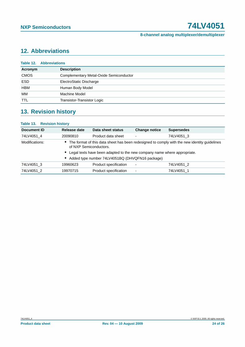
12. Abbreviations
13. Revision history
Table 12. Abbreviations
Acronym Description
CMOS Complementary Metal-Oxide Semiconductor
ESD ElectroStatic Discharge
HBM Human Body Model
MM Machine Model
TTL Transistor-Transistor Logic
Table 13. Revision history
Document ID Release date Data sheet status Change notice Supersedes
74LV4051_4 20090810 Product data sheet - 74LV4051_3
Modifications: • The format of this data sheet has been redesigned to comply with the new identity guidelinesof NXP Semiconductors.
• Legal texts have been adapted to the new company name where appropriate.
• Added type number 74LV4051BQ (DHVQFN16 package)
74LV4051_3 19960623 Product specification - 74LV4051_2
74LV4051_2 19970715 Product specification - 74LV4051_1
74LV4051_4 © NXP B.V. 2009. All rights reserved.
Product data sheet Rev. 04 — 10 August 2009 24 of 26

NXP Semiconductors 74LV40518-channel analog multiplexer/demultiplexer
14. Legal information
14.1 Data sheet status
[1] Please consult the most recently issued document before initiating or completing a design.
[2] The term ‘short data sheet’ is explained in section “Definitions”.
[3] The product status of device(s) described in this document may have changed since this document was published and may differ in case of multiple devices. The latest product statusinformation is available on the Internet at URL http://www.nxp.com.
14.2 Definitions
Draft — The document is a draft version only. The content is still underinternal review and subject to formal approval, which may result inmodifications or additions. NXP Semiconductors does not give anyrepresentations or warranties as to the accuracy or completeness ofinformation included herein and shall have no liability for the consequences ofuse of such information.
Short data sheet — A short data sheet is an extract from a full data sheetwith the same product type number(s) and title. A short data sheet is intendedfor quick reference only and should not be relied upon to contain detailed andfull information. For detailed and full information see the relevant full datasheet, which is available on request via the local NXP Semiconductors salesoffice. In case of any inconsistency or conflict with the short data sheet, thefull data sheet shall prevail.
14.3 Disclaimers
General — Information in this document is believed to be accurate andreliable. However, NXP Semiconductors does not give any representations orwarranties, expressed or implied, as to the accuracy or completeness of suchinformation and shall have no liability for the consequences of use of suchinformation.
Right to make changes — NXP Semiconductors reserves the right to makechanges to information published in this document, including withoutlimitation specifications and product descriptions, at any time and withoutnotice. This document supersedes and replaces all information supplied priorto the publication hereof.
Suitability for use — NXP Semiconductors products are not designed,authorized or warranted to be suitable for use in medical, military, aircraft,space or life support equipment, nor in applications where failure ormalfunction of an NXP Semiconductors product can reasonably be expectedto result in personal injury, death or severe property or environmental
damage. NXP Semiconductors accepts no liability for inclusion and/or use ofNXP Semiconductors products in such equipment or applications andtherefore such inclusion and/or use is at the customer’s own risk.
Applications — Applications that are described herein for any of theseproducts are for illustrative purposes only. NXP Semiconductors makes norepresentation or warranty that such applications will be suitable for thespecified use without further testing or modification.
Limiting values — Stress above one or more limiting values (as defined inthe Absolute Maximum Ratings System of IEC 60134) may cause permanentdamage to the device. Limiting values are stress ratings only and operation ofthe device at these or any other conditions above those given in theCharacteristics sections of this document is not implied. Exposure to limitingvalues for extended periods may affect device reliability.
Terms and conditions of sale — NXP Semiconductors products are soldsubject to the general terms and conditions of commercial sale, as publishedat http://www.nxp.com/profile/terms, including those pertaining to warranty,intellectual property rights infringement and limitation of liability, unlessexplicitly otherwise agreed to in writing by NXP Semiconductors. In case ofany inconsistency or conflict between information in this document and suchterms and conditions, the latter will prevail.
No offer to sell or license — Nothing in this document may be interpretedor construed as an offer to sell products that is open for acceptance or thegrant, conveyance or implication of any license under any copyrights, patentsor other industrial or intellectual property rights.
Export control — This document as well as the item(s) described hereinmay be subject to export control regulations. Export might require a priorauthorization from national authorities.
14.4 TrademarksNotice: All referenced brands, product names, service names and trademarksare the property of their respective owners.
15. Contact information
For more information, please visit: http://www .nxp.com
For sales office addresses, please send an email to: salesad [email protected]
Document status [1] [2] Product status [3] Definition
Objective [short] data sheet Development This document contains data from the objective specification for product development.
Preliminary [short] data sheet Qualification This document contains data from the preliminary specification.
Product [short] data sheet Production This document contains the product specification.
74LV4051_4 © NXP B.V. 2009. All rights reserved.
Product data sheet Rev. 04 — 10 August 2009 25 of 26

NXP Semiconductors 74LV40518-channel analog multiplexer/demultiplexer
16. Contents
1 General description . . . . . . . . . . . . . . . . . . . . . . 12 Features . . . . . . . . . . . . . . . . . . . . . . . . . . . . . . . 13 Ordering information . . . . . . . . . . . . . . . . . . . . . 24 Functional diagram . . . . . . . . . . . . . . . . . . . . . . 25 Pinning information . . . . . . . . . . . . . . . . . . . . . . 45.1 Pinning . . . . . . . . . . . . . . . . . . . . . . . . . . . . . . . 45.2 Pin description . . . . . . . . . . . . . . . . . . . . . . . . . 46 Functional description . . . . . . . . . . . . . . . . . . . 56.1 Function table . . . . . . . . . . . . . . . . . . . . . . . . . . 57 Limiting values. . . . . . . . . . . . . . . . . . . . . . . . . . 58 Recommended operating conditions. . . . . . . . 69 Static characteristics. . . . . . . . . . . . . . . . . . . . . 79.1 Test circuits . . . . . . . . . . . . . . . . . . . . . . . . . . . . 89.2 ON resistance . . . . . . . . . . . . . . . . . . . . . . . . . . 89.3 On resistance waveform and test circuit . . . . . 1010 Dynamic characteristics . . . . . . . . . . . . . . . . . 1110.1 Waveforms . . . . . . . . . . . . . . . . . . . . . . . . . . . 1310.2 Additional dynamic parameters . . . . . . . . . . . 1510.2.1 Test circuits . . . . . . . . . . . . . . . . . . . . . . . . . . . 1611 Package outline . . . . . . . . . . . . . . . . . . . . . . . . 1912 Abbreviations . . . . . . . . . . . . . . . . . . . . . . . . . . 2413 Revision history . . . . . . . . . . . . . . . . . . . . . . . . 2414 Legal information. . . . . . . . . . . . . . . . . . . . . . . 2514.1 Data sheet status . . . . . . . . . . . . . . . . . . . . . . 2514.2 Definitions . . . . . . . . . . . . . . . . . . . . . . . . . . . . 2514.3 Disclaimers . . . . . . . . . . . . . . . . . . . . . . . . . . . 2514.4 Trademarks . . . . . . . . . . . . . . . . . . . . . . . . . . . 2515 Contact information. . . . . . . . . . . . . . . . . . . . . 2516 Contents . . . . . . . . . . . . . . . . . . . . . . . . . . . . . . 26
© NXP B.V. 2009. All rights reserved.For more information, please visit: http://www.nxp.comFor sales office addresses, please send an email to: [email protected]
Date of release: 10 August 2009
Document identifier: 74LV4051_4
Please be aware that important notices concerning this document and the product(s)described herein, have been included in section ‘Legal information’.