747-8 airplane characteristics for airport planning scope and introduction 1 1.1 scope 2 1.2...
TRANSCRIPT

D6-58326-3 REV B DECEMBER 2012 i
747-8 Airplane Characteristics for Airport Planning
Boeing Commercial Airplanes

D6-58326-3 ii DECEMBER 2012 REV B
THIS PAGE INTENTIONALLY LEFT BLANK
D6-58326-3 REV B DECEMBER 2012 iii
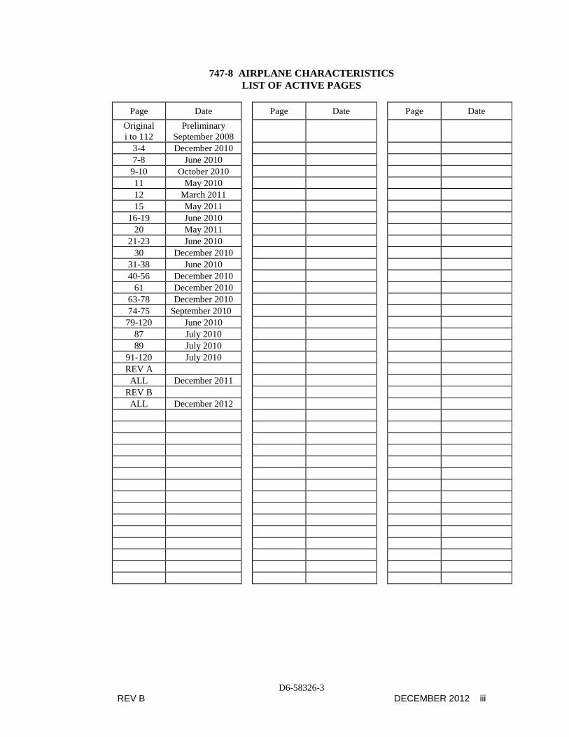
747-8 AIRPLANE CHARACTERISTICS LIST OF ACTIVE PAGES
Page Date Page Date Page Date
Original i to 112
Preliminary September 2008
3-4 December 2010 7-8 June 2010
9-10 October 2010 11 May 2010 12 March 2011 15 May 2011
16-19 June 2010 20 May 2011
21-23 June 2010 30 December 2010
31-38 June 2010 40-56 December 2010
61 December 2010 63-78 December 2010 74-75 September 2010
79-120 June 2010 87 July 2010 89 July 2010
91-120 July 2010 REV A
ALL December 2011 REV B
ALL December 2012

D6-58326-3 iv DECEMBER 2012 REV B
TABLE OF CONTENTS
SECTION TITLE PAGE
1.0 SCOPE AND INTRODUCTION 1 1.1 Scope 2 1.2 Introduction 3 1.3 A Brief Description of the 747-8 4
2.0 AIRPLANE DESCRIPTION 5 2.1 General Characteristics 6 2.2 General Dimensions 9 2.3 Ground Clearances 11 2.4 Interior Arrangement 13 2.5 Cabin Cross-Sections 15 2.6 Lower Cargo Compartments 18 2.7 Door Clearances 19
3.0 AIRPLANE PERFORMANCE 27 3.1 General Information 28 3.2 Payload/Range 29 3.3 FAA/EASA Takeoff Runway Length Requirements 31 3.4 FAA/EASA Landing Runway Length Requirements 39
4.0 GROUND MANEUVERING 41 4.1 General Information 42 4.2 Turning Radii 44 4.3 Clearance Radii 46 4.4 Visibility from Cockpit in Static Position 48 4.5 Runway and Taxiway Turn Paths 49 4.6 Runway Holding Bay 58
5.0 TERMINAL SERVICING 59 5.1 Airplane Servicing Arrangement - Typical Turnaround 61 5.2 Terminal Operations - Turnaround Station 63 5.3 Terminal Operations - En Route Station 67 5.4 Ground Servicing Connections 68 5.5 Engine Start Pneumatic Requirements 72 5.6 Ground Pneumatic Power Requirements - Heating/Cooling 75 5.7 Conditioned Air Flow Requirements 76 5.8 Ground Towing Requirements 77
6.0 JET ENGINE WAKE AND NOISE DATA 79 6.1 Jet Engine Exhaust Velocities and Temperatures 80 6.2 Airport and Community Noise 88

D6-58326-3 REV B DECEMBER 2012 v
TABLE OF CONTENTS (CONTINUED)
SECTION TITLE PAGE
7.0 PAVEMENT DATA 91 7.1 General Information 92 7.2 Landing Gear Footprint 95 7.3 Maximum Pavement Loads 96 7.4 Landing Gear Loading on Pavement 97 7.5 Flexible Pavement Requirements - U.S. Army Corps of 100
Engineers Method (S-77-1) and FAA Design Method 7.6 Flexible Pavement Requirements - LCN Conversion 103 7.7 Rigid Pavement Requirements - Portland Cement 106
Association Design Method 7.8 Rigid Pavement Requirements - LCN Conversion 109 7.9 Rigid Pavement Requirements - FAA Design Method 113 7.10 7.11
ACN/PCN Reporting System: Flexible and Rigid Pavements Nose Gear Tethering (Optional)
114 119
8.0 FUTURE 747-8 DERIVATIVE AIRPLANES 121
9.0 SCALED DRAWINGS 123 9.1 Scaled Drawings - 747-8, 747-8F 125

D6-58326-3 vi DECEMBER 2012 REV B
THIS PAGE INTENTIONALLY LEFT BLANK

D6-58326-3 REV B DECEMBER 2012 1
1.0 SCOPE AND INTRODUCTION
1.1 Scope
1.2 Introduction
1.3 A Brief Description of the 747-8

D6-58326-3 2 DECEMBER 2012 REV B
1.0 SCOPE AND INTRODUCTION
1.1 Scope
This document provides, in a standardized format, airplane characteristics data for general airport planning. Since operational practices vary among airlines, specific data should be coordinated with the using airlines prior to facility design. Boeing Commercial Airplanes should be contacted for any additional information required.
Content of the document reflects the results of a coordinated effort by representatives from the following organizations:
• Aerospace Industries Association
• Airports Council International – North America
• International Industry Working Group
• International Air Transport Association
The airport planner may also want to consider the information presented in the "Commercial Aircraft Design Characteristics - Trends and Growth Projections," for long range planning needs and can be accessed via the following website:
http://www.boeing.com/airports
The document is updated periodically and represents the coordinated efforts of the following organizations regarding future aircraft growth trends.
• International Civil Aviation Organization
• International Coordinating Council of Aerospace Industries Associations
• Airports Council International – North America and World Organizations
• International Industry Working Group
• International Air Transport Association

D6-58326-3 REV B DECEMBER 2012 3
1.2 Introduction
This document conforms to NAS 3601. It provides characteristics of the Boeing Model 747-8F (Freighter) and 747-8 (Intercontinental passenger) airplanes for airport planners, operators, airlines, architectural and engineering consultant organizations, and other interested industry agencies. Airplane changes and available options may alter model characteristics. The data presented herein reflects the certificated versions of the 747-8F and 747-8. The data will reflect typical airplanes in each model category. Data used is generic in scope and not customer-specific. The 747-8 series is an FAA Airplane Design Group VI and an ICAO Aerodrome Reference Code 4F category aircraft.
For additional information contact:
Boeing Commercial Airplanes P.O. Box 3707 Seattle, Washington 98124-2207 U.S.A. Attention: Manager, Airport Technology Mail Code 20-93 Email: [email protected] Fax: 206-662-0280

D6-58326-3 4 DECEMBER 2012 REV B
1.3 A Brief Description of the 747-8
The 747-8 is the latest derivative of the 747 family of airplanes and is offered in both Freighter and Passenger versions. The 747-8 is externally similar to the 747-400 with a higher gross weight, longer fuselage and increased wingspan. The 747-8 Freighter retains the 747-400F nose cargo door, continuing the capability to easily load outsized cargo. The 747-8 has new high bypass ratio engines, GEnx 2B, which are the quiet and efficient GEnx engines developed for the 787 aircraft. The 747-8 has a cruise speed of Mach 0.845 for the Freighter and Mach 0.855 for the Intercontinental, which are increased speeds from the 747-400 series, due to changes in the wing, the new raked wingtips, and the GEnx engines. The 747-8F entered revenue service in October 2011. The 747-8 entered revenue service in 2012.
Other characteristics unique to the 747-8 compared to the 747-400 include:
• Next generation advanced alloys
• New wing design, including new airfoils and raked wingtips replacing the winglets
• GEnx-2B67 engines, including light weight composite fan case and fan blades, modified to provide current 747-8 bleed requirements
• Improved flight deck while preserving 747-400 operational commonality
• New interior architecture to enhance passenger experience
• Improved aerodynamic efficiency and reduced seat-mile cost (Passenger variant) and reduced ton-mile cost (Freighter variant)

D6-58326-3 REV B DECEMBER 2012 5
2.0 AIRPLANE DESCRIPTION
2.1 General Characteristics
2.2 General Dimensions
2.3 Ground Clearances
2.4 Interior Arrangements
2.5 Cabin Cross Sections
2.6 Lower Cargo Compartments
2.7 Door Clearances

D6-58326-3 6 DECEMBER 2012 REV B
2.0 AIRPLANE DESCRIPTION
2.1 General Characteristics
Maximum Design Taxi Weight (MTW). Maximum weight for ground maneuver as limited by aircraft strength and airworthiness requirements. (It includes weight of taxi and run-up fuel.)
Maximum Design Takeoff Weight (MTOW). Maximum weight for takeoff as limited by aircraft strength and airworthiness requirements. (This is the maximum weight at start of the takeoff run.)
Maximum Design Landing Weight (MLW). Maximum weight for landing as limited by aircraft strength and airworthiness requirements.
Maximum Design Zero Fuel Weight (MZFW). Maximum weight allowed before usable fuel and other specified usable agents must be loaded in defined sections of the aircraft as limited by strength and airworthiness requirements.
Operating Empty Weight (OEW). Weight of structure, powerplant, furnishing systems, unusable fuel and other unusable propulsion agents, and other items of equipment that are considered an integral part of a particular airplane configuration. Also included are certain standard items, personnel, equipment, and supplies necessary for full operations, excluding usable fuel and payload.
Maximum Payload. Maximum design zero fuel weight minus operational empty weight.
Maximum Seating Capacity. The maximum number of passengers specifically certificated or anticipated for certification.
Maximum Cargo Volume. The maximum space available for cargo.
Usable Fuel. Fuel available for aircraft propulsion.

D6-58326-3 REV B DECEMBER 2012 7
CHARACTERISTICS UNITS 747-8F 747-8F
MAX DESIGN
TAXI WEIGHT
POUNDS 978,000 990,000
KILOGRAMS 443,613 449,056
MAX DESIGN
TAKEOFF WEIGHT
POUNDS 975,000 987,000
KILOGRAMS 442,253 447,696
MAX DESIGN
LANDING WEIGHT
POUNDS 761,000 763,000
KILOGRAMS 345,184 346,091
MAX DESIGN
ZERO FUEL WEIGHT
POUNDS 725,000 727,000
KILOGRAMS 328,854 329,762
OPERATING
EMPTY WEIGHT (1)
POUNDS 434,600 434,600
KILOGRAMS 197,131 197,131
MAX STRUCTURAL
PAYLOAD (1)
POUNDS 290,400 292,400
KILOGRAMS 131,723 132,630
TYPICAL CARGO – MAIN DECK
CONTAINERS
CUBIC FEET 24,462 24,462
CUBIC METERS 693 693
MAX CARGO - LOWER DECK
CONTAINERS (LD-1)
CUBIC FEET 5,850 5,850
CUBIC METERS 166 166
MAX CARGO - LOWER DECK
BULK CARGO
CUBIC FEET 520 520
CUBIC METERS 14.7 14.7
USABLE FUEL CAPACITY U.S. GALLONS 59,734 (2) 59,734 (2)
LITERS 226,118 226,118
POUNDS 400,218 400,218
KILOGRAMS 181,536 181,536 NOTES:
1. ESTIMATED WEIGHTS FOR ENGINE/AIRFRAME CONFIGURATION SHOWN. OPERATING EMPTY WEIGHT REFLECTS STANDARD ITEM ALLOWANCES. ACTUAL OEW AND PAYLOAD WILL VARY WITH AIRPLANE AND AIRLINE CONFIGURATION. CONSULT USING AIRLINE FOR VALUES.
2. 747-8F IS NOT DESIGNED WITH TAIL FUEL TANKS
2.1.1 GENERAL CHARACTERISTICS MODEL 747-8F

D6-58326-3 8 DECEMBER 2012 REV B
CHARACTERISTICS UNITS 747-8
MAX DESIGN
TAXI WEIGHT
POUNDS 990,000
KILOGRAMS 449,056
MAX DESIGN
TAKEOFF WEIGHT
POUNDS 987,000
KILOGRAMS 447,696
MAX DESIGN
LANDING WEIGHT
POUNDS 688,000
KILOGRAMS 312,072
MAX DESIGN
ZERO FUEL WEIGHT
POUNDS 651,000
KILOGRAMS 295,289
OPERATING
EMPTY WEIGHT (1)
POUNDS 485,300
KILOGRAMS 220,128
MAX STRUCTURAL
PAYLOAD
POUNDS 167,700
KILOGRAMS 76,067
TYPICAL SEATING CAPACITY
(INCLUDES UPPER DECK)
UPPER DECK 48 BUSINESS CLASS
MAIN DECK 19 FIRST, 96 BUSINESS, 352 ECONOMY
MAX CARGO - LOWER DECK
CONTAINERS (LD-1)
CUBIC FEET 5,705
CUBIC METERS 162
MAX CARGO - LOWER DECK
BULK CARGO
CUBIC FEET 640
CUBIC METERS 18.1
USABLE FUEL CAPACITY U.S. GALLONS 63,034 (2)
LITERS 238,610
POUNDS 426,109
KILOGRAMS 193,280
NOTES:
1. ESTIMATED WEIGHTS FOR ENGINE/AIRFRAME CONFIGURATION SHOWN. OPERATING EMPTY WEIGHT REFLECTS STANDARD ITEM ALLOWANCES. ACTUAL OEW AND PAYLOAD WILL VARY WITH AIRPLANE AND AIRLINE CONFIGURATION. CONSULT USING AIRLINE FOR VALUES.
2. VALUE INCLUDES TAIL FUEL TANK VOLUME.
2.1.2 GENERAL CHARACTERISTICS MODEL 747-8

D6-58326-3 REV B DECEMBER 2012 9
2.2.1 GENERAL DIMENSIONS MODEL 747-8F

D6-58326-3 10 DECEMBER 2012 REV B
2.2.2 GENERAL DIMENSIONS MODEL 747-8

D6-58326-3 REV B DECEMBER 2012 11
MINIMUM MAXIMUM FT - IN M FT - IN M A 38 - 8 11.79 40 - 3 12.24 B 15 - 7 4.75 17 – 2 5.24 C 15 - 8 4.78 17 - 1 5.19 D 9 - 0 2.75 10 - 4 3.14 E 5 - 9 1.75 6 - 8 2.04 F 9 - 6 2.90 10 - 7 3.21 G 10 - 1 3.07 11 - 3 3.42 K 62 - 3 18.97 64 - 2 19.56 L 28 - 2 8.58 30 - 1 9.16 M 21 - 5 6.52 22 - 5 6.48 N 6 - 3 1.90 6 - 11 2.10 P 2 - 5 0.73 3 - 3 0.99 U 16 - 3 4.95 17 - 3 5.25
NOTES: VERTICAL CLEARANCES SHOWN OCCUR DURING MAXIMUM VARIATIONS OF AIRPLANE ATTITUDE. COMBINATIONS OF AIRPLANE LOADING/UNLOADING ACTIVITIES THAT PRODUCE THE GREATEST POSSIBLE VARIATIONS OF ATTITUDE WERE USED TO ESTABLISH THE VARIATIONS SHOWN. DURING ROUTINE SERVICING, THE AIRPLANE REMAINS RELATIVELY STABLE; PITCH AND ELEVATION CHANGES OCCUR SLOWLY.
A GSE TETHERING DEVICE MAY BE USED TO MAINTAIN STABILITY BETWEEN THE MAIN DECK DOOR SILL AND THE LOADING DOCK. CARGO BRIDGE ATTACHMENT FITTINGS LOCATED ON THE NOSE DOOR SILL AT THE FORWARD EDGE OF THE MAIN CARGO DOOR DECK MAY BE USED FOR NOSE DOOR SILL STABILIZATION.
2.3.1 GROUND CLEARANCES MODEL 747-8F

D6-58326-3 12 DECEMBER 2012 REV B
MINIMUM MAXIMUM FT - IN M FT - IN M
A 31 - 0 9.44 32 - 3 9.84 B 24 – 10 7.56 25 – 11 7.90 C 15 – 8 4.78 16 – 11 5.16 D 9 – 0 2.75 10 – 2 3.09 E 5 – 9 1.75 6 – 7 2.01 F 9 – 6 2.89 10 – 5 3.18 G 10 – 1 3.07 11 – 1 3.38 J 16 – 3 4.95 17 – 5 5.32 K 62 - 3 18.97 64 – 0 19.51 L 28 – 2 8.58 29 – 11 9.12 M 21 - 4 6.51 22 - 4 6.80 N 6 – 3 1.90 6 – 10 2.07 P 2 - 5 0.73 3 – 2 0.96 S 16 – 0 4.87 16 – 10 5.14 T 16 - 3 4.95 17 - 1 5.20 V 16 - 2 4.94 16 - 9 5.12
NOTES: VERTICAL CLEARANCES SHOWN OCCUR DURING MAXIMUM VARIATIONS OF AIRPLANE ATTITUDE. COMBINATIONS OF AIRPLANE LOADING/UNLOADING ACTIVITIES THAT PRODUCE THE GREATEST POSSIBLE VARIATIONS OF ATTITUDE WERE USED TO ESTABLISH THE VARIATIONS SHOWN. DURING ROUTINE SERVICING, THE AIRPLANE REMAINS RELATIVELY STABLE; PITCH AND ELEVATION CHANGES OCCUR SLOWLY
2.3.2 GROUND CLEARANCES MODEL 747-8

D6-58326-3 REV B DECEMBER 2012 13
2.4.1 TYPICAL INTERIOR ARRANGEMENTS, THREE CLASS, 467 PASSENGERS MODEL 747-8
D6-58326-3 14 DECEMBER 2012 REV B
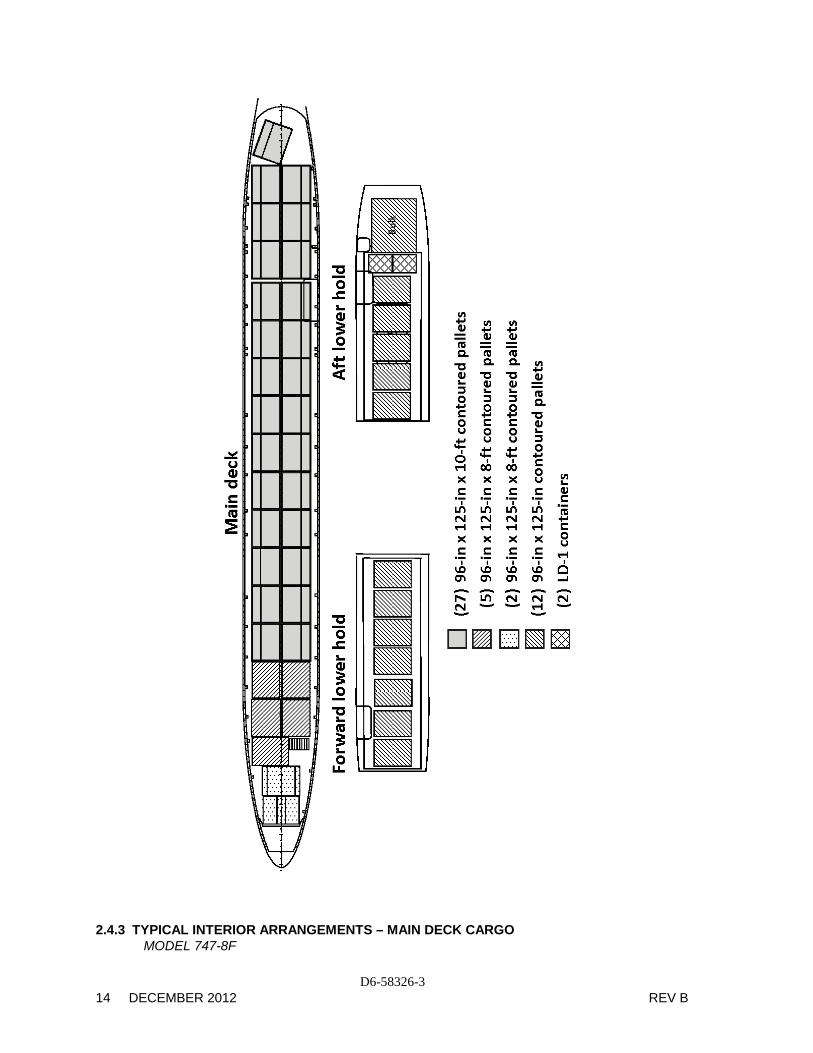
2.4.3 TYPICAL INTERIOR ARRANGEMENTS – MAIN DECK CARGO MODEL 747-8F

D6-58326-3 REV B DECEMBER 2012 15
2.5.1 CABIN CROSS-SECTIONS MODEL 747-8

D6-58326-3 16 DECEMBER 2012 REV B
2.5.2 CABIN CROSS-SECTIONS MODEL 747-8

D6-58326-3 REV B DECEMBER 2012 17
2.5.3 CABIN CROSS-SECTIONS MODEL 747-8

D6-58326-3 18 DECEMBER 2012 REV B
2.6 LOWER CARGO COMPARTMENTS - CONTAINERS AND BULK CARGO MODEL 747-8, 747-8F

D6-58326-3 REV B DECEMBER 2012 19
2.7.1 DOOR CLEARANCES - MAIN ENTRY DOOR LOCATIONS
MODEL 747-8, 747-8F

D6-58326-3 20 DECEMBER 2012 REV B
PLAN VIEW
VIEW LOOKING FORWARDSIDE VIEW
2.7.2 DOOR CLEARANCES - MAIN ENTRY DOORS 1-4
MODEL 747-8, 747-8F

D6-58326-3 REV B DECEMBER 2012 21
PLAN VIEW
VIEW LOOKING FORWARD
2.7.3 DOOR CLEARANCES - MAIN ENTRY DOOR 5
MODEL 747-8

D6-58326-3 22 DECEMBER 2012 REV B
2.7.4 DOOR CLEARANCES – LOWER FORWARD CARGO COMPARTMENT MODEL 747-8, 747-8F

D6-58326-3 REV B DECEMBER 2012 23
2.7.5 DOOR CLEARANCES – LOWER AFT CARGO COMPARTMENT
MODEL 747-8, 747-8F

D6-58326-3 24 DECEMBER 2012 REV B
2.7.6 DOOR CLEARANCES - BULK CARGO COMPARTMENT
MODEL 747-8

D6-58326-3 REV B DECEMBER 2012 25
2.7.7 DOOR CLEARANCES – MAIN DECK CARGO DOOR MODEL 747-8F

D6-58326-3 26 DECEMBER 2012 REV B
2.7.8 DOOR CLEARANCES - NOSE CARGO DOOR MODEL 747-8F

D6-58326-3 REV B DECEMBER 2012 27
3.0 AIRPLANE PERFORMANCE
3.1 General Information
3.2 Payload/Range
3.3 FAA/EASA Takeoff Runway Length Requirements
3.4 FAA/EASA Landing Runway Length Requirements

D6-58326-3 28 DECEMBER 2012 REV B
3.0 AIRPLANE PERFORMANCE 3.1 General Information
The graphs in Section 3.2 provide information on payload-range capability of the 747-8 airplane. To use these graphs; if the trip range and zero fuel weight (OEW + payload) are known, the approximate takeoff weight can be found; limited by maximum zero fuel weight, maximum design takeoff weight, or fuel capacity.
The graphs in Section 3.3 provide information on FAA/EASA takeoff runway length requirements with typical engines and various conditions. Maximum takeoff weights shown on the graphs are the heaviest for the particular airplane models with the corresponding engines. Standard day temperatures for pressure altitudes shown on the FAA/EASA takeoff graphs are given below:
PRESSURE ALTITUDE STANDARD DAY TEMP
FEET METERS oF oC
0 0 59.0 15.0
2,000 610 51.9 11.0
4,000 1,219 44.7 7.1
6,000 1,829 37.6 3.1
8,000 2,438 30.5 -0.8
10,000 3,048 23.3 -4.8
12,000 3,658 16.2 -8.8
14,000 4,267 9.1 -12.7
The graphs in Section 3.4 provide information on landing runway length requirements for different airplane weights and airport altitudes. The maximum landing weights shown are the heaviest for the particular airplane model.

D6-58326-3 REV B DECEMBER 2012 29
3.2.1 PAYLOAD/RANGE MODEL 747-8F

D6-58326-3 30 DECEMBER 2012 REV B
3.2.2 PAYLOAD/RANGE
MODEL 747-8

D6-58326-3 REV B DECEMBER 2012 31
3.3.1 FAA/EASA TAKEOFF RUNWAY LENGTH REQUIREMENTS - STANDARD DAY MODEL 747-8F

D6-58326-3 32 DECEMBER 2012 REV B
3.3.2 FAA/EASA TAKEOFF RUNWAY LENGTH REQUIREMENTS - STANDARD DAY + 27°F (STD + 15°C)
MODEL 747-8F

D6-58326-3 REV B DECEMBER 2012 33
3.3.3 FAA/EASA TAKEOFF RUNWAY LENGTH REQUIREMENTS - STANDARD DAY + 45°F (STD + 25°C)
MODEL 747-8F

D6-58326-3 34 DECEMBER 2012 REV B
3.3.4 FAA/EASA TAKEOFF RUNWAY LENGTH REQUIREMENTS –
STANDARD DAY + 63°F (STD + 35°C) MODEL 747-8F

D6-58326-3 REV B DECEMBER 2012 35
3.3.5 FAA/EASA TAKEOFF RUNWAY LENGTH REQUIREMENTS - STANDARD DAY
MODEL 747-8

D6-58326-3 36 DECEMBER 2012 REV B
3.3.6 FAA/EASA TAKEOFF RUNWAY LENGTH REQUIREMENTS - STANDARD DAY + 27°F (STD + 15°C)
MODEL 747-8

D6-58326-3 REV B DECEMBER 2012 37
3.3.7 FAA/EASA TAKEOFF RUNWAY LENGTH REQUIREMENTS - STANDARD DAY + 45°F (STD + 25°C)
MODEL 747-8

D6-58326-3 38 DECEMBER 2012 REV B
3.3.8 FAA/EASA TAKEOFF RUNWAY LENGTH REQUIREMENTS –
STANDARD DAY + 63°F (STD + 35°C) MODEL 747-8

D6-58326-3 REV B DECEMBER 2012 39
3.4.1 FAA/EASA LANDING RUNWAY LENGTH REQUIREMENTS - FLAPS 30 MODEL 747-8F AND 747-8

D6-58326-3 40 DECEMBER 2012 REV B
3.4.2 FAA/EASA LANDING RUNWAY LENGTH REQUIREMENTS - FLAPS 25
MODEL 747-8F AND 747-8

D6-58326-3 REV B DECEMBER 2012 41
4.0 GROUND MANEUVERING
4.1 General Information
4.2 Turning Radii
4.3 Clearance Radii
4.4 Visibility from Cockpit in Static Position
4.5 Runway and Taxiway Turn Paths
4.6 Runway Holding Bay

D6-58326-3 42 DECEMBER 2012 REV B
4.0 GROUND MANEUVERING
4.1 General Information
The 747-8 main landing gear consists of four main struts, each strut with four wheels. This geometric arrangement of the four main gears results in somewhat different ground maneuvering characteristics from those experienced with typical landing gear aircraft.
Basic factors that influence the geometry of the turn include:
1. Nose wheel steering angle
2. Engine power settings
3. Center of gravity location
4. Airplane weight
5. Pavement surface conditions
6. Amount of differential braking
7. Ground speed
8. Main landing gear steering
The steering system of the 747-8 incorporates steering of the main body landing gear in addition to the nose gear steering. This body gear steering system is hydraulically actuated and is programmed electrically to provide steering ratios proportionate to the nose gear steering angles. During takeoff and landing, the body gear steering system is centered, mechanically locked, and depressurized.
Steering of the main body gear has the following advantages over ground maneuvering without this steering feature; overall improved maneuverability, including improved nose gear tracking; elimination of the need for differential braking during ground turns, with subsequent reduced brake wear; reduced thrust requirements; lower main gear stress levels; and reduced tire scrubbing. The turning radii shown in Section 4.2 are derived from a previous test involving a 747-200. The 747-8 is expected to follow the same maneuvering characteristics.

D6-58326-3 REV B DECEMBER 2012 43
NOSE GEAR ANGLE (DEG)
NOSE GEAR/BODY GEAR TURN RATIOS
4.1.1 GENERAL INFORMATION – BODY GEAR STEERING SYSTEM
MODEL 747-8, 747-8F

D6-58326-3 44 DECEMBER 2012 REV B
45°
50°
55°
60°
65°
70°
Nose Gear AxleProjection
R1
R2R3
R4
R5
R6
Turn Center(Typical for Steering
Angles Shown)
NOTES: DATA SHOWN FOR AIRPLANE WITH BODY GEAR STEERING ACTUAL OPERATING TURNING RADII MAY BE GREATER THAN SHOWN CONSULT WITH AIRLINE FOR SPECIFIC OPERATING PROCEDURE DIMENSIONS ROUNDED TO NEAREST FOOT AND 0.1 METER
STEERING
ANGLE R1
INNER GEAR R2
OUTER GEAR R3
NOSE GEAR R4
WINGTIP R5
NOSE R6
TAIL (DEG) FT M FT M FT M FT M FT M FT M
30 139 42.4 181 55.2 188 57.3 280 85.3 199 60.7 233 71.0 35 111 33.8 153 46.6 164 50.0 252 76.8 177 54.0 210 64.0 40 89 27.1 131 39.9 147 44.8 231 70.4 161 49.1 193 58.8 45 72 21.9 113 34.4 134 40.8 214 65.2 150 45.7 180 54.9 50 57 17.4 98 29.9 124 37.8 200 61.0 141 43.0 170 51.8 55 44 13.4 86 26.2 116 35.4 188 57.3 134 40.8 162 49.4 60 33 10.1 74 22.6 110 33.5 177 54.0 129 39.3 155 47.2 65 22 6.7 64 19.5 105 32.0 168 51.2 125 38.1 149 45.4
70 (MAX) 13 4.0 55 16.8 101 30.8 159 48.5 123 37.5 144 43.9 4.2.1 TURNING RADII – NO SLIP ANGLE – WITH BODY GEAR STEERING
MODEL 747-8, 747-8F

D6-58326-3 REV B DECEMBER 2012 45
45°
50°
55°
60°
65°
70°
Nose Gear AxleProjection
R1
R2R3
R4
R5
R6
Turn Center(Typical for Steering
Angles Shown)
NOTES: DATA SHOWN FOR AIRPLANE WITH BODY GEAR STEERING INOPERATIVE ACTUAL OPERATING TURNING RADII MAY BE GREATER THAN SHOWN CONSULT WITH AIRLINE FOR SPECIFIC OPERATING PROCEDURE DIMENSIONS ROUNDED TO NEAREST FOOT AND 0.1 METER
STEERING
ANGLE R1
INNER GEAR R2
OUTER GEAR R3
NOSE GEAR R4
WINGTIP R5
NOSE R6
TAIL (DEG) FT M FT M FT M FT M FT M FT M
30 148 45.1 190 57.9 198 60.4 287 87.5 209 63.7 240 73.2 35 118 36.0 160 48.8 173 52.7 258 78.6 186 56.7 215 65.5 40 95 29.0 137 41.8 155 47.2 236 71.9 169 51.5 196 59.7 45 77 23.5 118 36.0 141 43.0 218 66.4 157 47.9 182 55.5 50 61 18.6 103 31.4 130 39.6 203 61.9 148 45.1 171 52.1 55 47 14.3 89 27.1 122 37.2 190 57.9 141 43.0 162 49.4 60 36 11.0 77 23.5 116 35.4 178 54.3 135 41.1 155 47.2 65 25 7.6 66 20.1 111 33.8 168 51.2 131 39.9 149 45.4
70 (MAX) 15 4.6 57 17.4 107 32.6 159 48.5 128 39.0 143 43.6 4.2.2 TURNING RADII – NO SLIP ANGLE –BODY GEAR STEERING INOPERATIVE
MODEL 747-8, 747-8F

D6-58326-3 46 DECEMBER 2012 REV B
R3 - Nose
Gear
EffectiveSteeringAngle
R5 - Nose
R4 - Wingtip
R6 - T
ail
Theoretical Center of Turn forMinimum Turning Radius.Slow Continuous Turn.No Differential Thrust.No Differential Braking.
Notes:
• 6° Tire Slip Angle – Approximate Only For 70° Maximum Turn Angle
• Consult Airline For Actual Operating Data.
AIRPLANE
EFFECTIVE TURNING
X
Y
A
R3
R4
R5
R6
MODEL ANGLE (DEG) FT M FT M FT M FT M FT M FT M FT M
747-8, 747-8F 64 93 28.3 46 14.0 172 52.4 105 32.0 170 51.8 126 38.4 153 46.6
NOTE: DIMENSIONS ARE ROUNDED TO THE NEAREST FOOT AND 0.1 METER.
4.3.1 CLEARANCE RADII – WITH BODY GEAR STEERING
MODEL 747-8, 747-8F

D6-58326-3 REV B DECEMBER 2012 47
R3 - Nose
Gear
EffectiveSteeringAngle
R5 - Nose
R4 - Wingtip
R6 - T
ail
Theoretical Center of Turn forMinimum Turning Radius.Slow Continuous Turn.No Differential Thrust.No Differential Braking.
Notes:
• Body Gear Steering Inoperative Rarely Occurs. Data Provided As Reference Only
• 9° Tire Slip Angle – Approximate Only For 60° Turn Angle (Optimum Max Steering Angle)
• Consult Airline For Actual Operating Data.
AIRPLANE
EFFECTIVE TURNING
X
Y
A
R3
R4
R5
R6
MODEL ANGLE (DEG) FT M FT M FT M FT M FT M FT M FT M
747-8, 747-8F 51 98 29.9 79 24.1 228 69.5 129 39.3 200 61.0 146 44.5 169 51.5
NOTE: DIMENSIONS ARE ROUNDED TO THE NEAREST FOOT AND 0.1 METER. 4.3.2 CLEARANCE RADII – BODY GEAR STEERING INOPERATIVE
MODEL 747-8, 747-8F

D6-58326-3 48 DECEMBER 2012 REV B
4.4 VISIBILITY FROM COCKPIT IN STATIC POSITION MODEL 747-8, 747-8F

D6-58326-3 REV B DECEMBER 2012 49
4.5.1 RUNWAY AND TAXIWAY TURNPATHS - RUNWAY-TO-TAXIWAY, 90 DEGREES, COCKPIT OVER CENTERLINE (FAA GROUP VI RADIUS/FILLET TO GROUP V TAXIWAY)
MODEL 747-8, 747-8F

D6-58326-3 50 DECEMBER 2012 REV B
4.5.2 RUNWAY AND TAXIWAY TURNPATHS - RUNWAY-TO-TAXIWAY, 90 DEGREES, COCKPIT
OVER CENTERLINE (FAA GROUP VI RADIUS/FILLET TO GROUP VI TAXIWAY) MODEL 747-8, 747-8F

D6-58326-3 REV B DECEMBER 2012 51
4.5.3 RUNWAY AND TAXIWAY TURNPATHS - RUNWAY-TO-TAXIWAY, 90 DEGREES,
JUDGMENTAL OVERSTEER (FAA GROUP V RADIUS/FILLET TO GROUP V TAXIWAY) MODEL 747-8, 747-8F

D6-58326-3 52 DECEMBER 2012 REV B
4.5.4 RUNWAY AND TAXIWAY TURNPATHS - RUNWAY-TO-TAXIWAY, MORE THAN 90 DEGREES,
COCKPIT OVER CENTERLINE (FAA GROUP VI RADIUS TO GROUP V TAXIWAY) MODEL 747-8, 747-8F

D6-58326-3 REV B DECEMBER 2012 53
4.5.5 RUNWAY AND TAXIWAY TURNPATHS - RUNWAY-TO-TAXIWAY, MORE THAN 90 DEGREES,
COCKPIT OVER CENTERLINE (FAA GROUP VI RADIUS TO GROUP VI TAXIWAY) MODEL 747-8, 747-8F

D6-58326-3 54 DECEMBER 2012 REV B
4.5.6 RUNWAY AND TAXIWAY TURNPATHS - RUNWAY-TO-TAXIWAY, MORE THAN 90 DEGREES, JUDGMENTAL OVERSTEER (FAA GROUP V RADIUS TO GROUP V TAXIWAY)
MODEL 747-8, 747-8F

D6-58326-3 REV B DECEMBER 2012 55
4.5.7 RUNWAY AND TAXIWAY TURNPATHS - TAXIWAY -TO-TAXIWAY, 90 DEGREES, COCKPIT
OVER CENTERLINE (FAA GROUP VI RADIUS TO GROUP V TAXIWAYS) MODEL 747-8, 747-8F

D6-58326-3 56 DECEMBER 2012 REV B
4.5.8 RUNWAY AND TAXIWAY TURNPATHS - TAXIWAY -TO-TAXIWAY, 90 DEGREES, COCKPIT
OVER CENTERLINE (FAA GROUP VI RADIUS TO GROUP VI TAXIWAYS) MODEL 747-8, 747-8F

D6-58326-3 REV B DECEMBER 2012 57
4.5.9 RUNWAY AND TAXIWAY TURNPATHS - TAXIWAY -TO-TAXIWAY, 90 DEGREES,
JUDGMENTAL OVERSTEER (FAA GROUP V RADIUS TO GROUP V TAXIWAY) MODEL 747-8, 747-8F

D6-58326-3 58 DECEMBER 2012 REV B
4.6 RUNWAY HOLDING BAY
MODEL 747-8, 747-8F

D6-58326-3 REV B DECEMBER 2012 59
5.0 TERMINAL SERVICING
5.1 Airplane Servicing Arrangement - Typical Turnaround
5.2 Terminal Operations - Turnaround Station
5.3 Terminal Operations - En Route Station
5.4 Ground Servicing Connections
5.5 Engine Starting Pneumatic Requirements
5.6 Ground Pneumatic Power Requirements
5.7 Conditioned Air Requirements
5.8 Ground Towing Requirements

D6-58326-3 60 DECEMBER 2012 REV B
5.0 TERMINAL SERVICING
During turnaround at the terminal, certain services must be performed on the aircraft, usually within a given time, to meet flight schedules. This section shows service vehicle arrangements, schedules, locations of service points, and typical service requirements. The data presented in this section reflect ideal conditions for a single airplane. Service requirements may vary according to airplane condition and airline procedure.
Section 5.1 shows typical arrangements of ground support equipment during turnaround. When the auxiliary power unit (APU) is used, the electrical, air start, and air-conditioning service vehicles may not be required. Passenger loading bridges or portable passenger stairs could be used to load or unload passengers.
Sections 5.2 and 5.3 show typical service times at the terminal. These charts give typical schedules for performing service on the airplane within a given time. Service times could be rearranged to suit availability of personnel, airplane configuration, and degree of service required.
Section 5.4 shows the locations of ground service connections in graphic and in tabular forms. Typical capacities and service requirements are shown in the tables. Services with requirements that vary with conditions are described in subsequent sections.
Section 5.5 shows typical sea level air pressure and flow requirements for starting different engines. The curves are based on an engine start time of 90 seconds.
Section 5.6 shows pneumatic requirements for heating and cooling (air conditioning) using high pressure air to run the air cycle machine. The curves show airflow requirements to heat or cool the airplane within a given time and ambient conditions. Maximum allowable pressure and temperature for air cycle machine operation are
60 psia and 450oF, respectively.
Section 5.7 shows pneumatic requirements for heating and cooling the airplane, using low pressure conditioned air. This conditioned air is supplied through an 8-in ground air connection (GAC) directly to the passenger cabin, bypassing the air cycle machines.
Section 5.8 shows ground towing requirements for various ground surface conditions.

D6-58326-3 REV B DECEMBER 2012 61
5.1.1 AIRPLANE SERVICING ARRANGEMENT - TYPICAL TURNAROUND
MODEL 747-8

D6-58326-3 62 DECEMBER 2012 REV B
5.1.2 AIRPLANE SERVICING ARRANGEMENT - TYPICAL TURNAROUND
MODEL 747-8F

D6-58326-3 REV B DECEMBER 2012 63
5.2.1 TERMINAL OPERATIONS - TURNAROUND STATION – ALL PASSENGER
MODEL 747-8

D6-58326-3 64 DECEMBER 2012 REV B
5.2.2 TERMINAL OPERATIONS - TURNAROUND STATION – ALL CARGO, NOSE DOOR LOADING
MODEL 747-8F

D6-58326-3 REV B DECEMBER 2012 65
5.2.3 TERMINAL OPERATIONS - TURNAROUND STATION – ALL CARGO, SIDE DOOR LOADING
MODEL 747-8F

D6-58326-3 66 DECEMBER 2012 REV B
5.2.4 TERMINAL OPERATIONS – TURNAROUND STATION – ALL CARGO, NOSE AND SIDE DOOR LOADING
MODEL 747-8F

D6-58326-3 REV B DECEMBER 2012 67
5.3.1 TERMINAL OPERATIONS - EN ROUTE STATION - ALL PASSENGER MODEL 747-8

D6-58326-3 68 DECEMBER 2012 REV B
5.4.1 GROUND SERVICE CONNECTIONS
MODEL 747-8F

D6-58326-3 REV B DECEMBER 2012 69
5.4.2 GROUND SERVICE CONNECTIONS
MODEL 747-8

D6-58326-3 70 DECEMBER 2012 REV B
DISTANCE AFT OF
DISTANCE FROM AIRPLANE CENTERLINE
HEIGHT ABOVE GROUND
SYSTEM NOSE LH SIDE RH SIDE MINIMUM MAXIMUM FT-IN M FT-IN M FT-IN M FT-IN M FT-IN M
ELECTRICAL TWO CO-LOCATED
CONNECTORS - 90 KVA, 115/120 V AC 400 HZ, 3-PHASE EA.
26 - 9
8.15
-
-
3 - 4
1.02
8 - 1
2.46
9 - 3
2.82
FUEL OUTBOARD UNDER- WING
PRESSURE CONNECTORS (2 EACH WING)
INBOARD UNDER- WING PRESSURE CONNECTORS (2 EACH WING)
MAX FUELING RATE 500 US GPM (1,890 LPM) PER NOZZLE
TOTAL MAX FUEL PRESSURE 50 PSIG (3.52 KG/CM2)
FUELING CONTROL PANEL
119 - 7
118 - 9
117 - 3
36.45
36.20
35.74
47 – 7
46 – 7
44 – 10
14.50
14.20
13.67
47 – 7
46 – 7 -
14.50
14.20 -
15 – 4
15 – 3
15 - 3
4.67
4.65
4.65
16 – 0
15 – 10
15 - 9
4.88
4.83
4.80
WING FUEL VENT TAIL FUEL VENT [1]
166 - 4 239 - 7
50.70 73.03
92 - 7 -
28.22 -
92 - 7 29 - 10
28.22 9.09
16 - 10 26 - 9
5.13 8.15
19 - 3 28 - 3
5.87 8.61
FUEL TANK VOLUME 747-8F 747-8 RESERVE U.S. GALLONS 1,534 EACH 1534 EACH NO 1 & 4 LITERS 5,806 EACH 5,806 EACH MAIN U.S. GALLONS 5,320 EACH 5,320 EACH NO 1 & 4 LITERS 20,138 EACH 20,138 EACH MAIN U.S. GALLONS 14,430 EACH 14,430 EACH NO 2 & 3 LITERS 54,623 EACH 54,623 EACH CENTER WING U.S. GALLONS 17,000 17,000 LITERS 64,352 64,352 HORIZONTAL STABILIZER U.S. GALLONS - - LITERS - - TOTAL USABLE U.S. GALLONS 59,734 59,734 LITERS 226,113 226,113
[1] PASSENGER AIRPLANE ONLY
5.4.3 GROUND SERVICE CONNECTIONS MODEL 747-8, 747-8F

D6-58326-3 REV B DECEMBER 2012 71
DISTANCE AFT OF DISTANCE FROM AIRPLANE CENTERLINE
HEIGHT ABOVE GROUND
SYSTEM NOSE LH SIDE RH SIDE MINIMUM MAXIMUM FT-IN M FT-IN M FT-IN M FT-IN M FT-IN M
LAVATORY ONE SERVICE PANEL: THREE CONNECTIONS DRAIN: ONE 4-IN (10.0 CM) FLUSH: TWO 1-IN (3.0 CM) FLUSH REQS: FLOW: 10 GPM (38 LPM) , 30 PSIG (2.11 KG/CM2)
TOTAL CAPACITY, 4 TANKS 300 US GAL (1,135 L)
178 – 4
54.37
-
-
-
-
8 - 8
2.64
9 - 8
2.95
PNEUMATIC TWO 3-IN (7.67 CM) HIGH- PRESSURE PORTS TWO 8-IN (20 CM) GROUND CONDITIONED AIR CONNECTIONS
109-10 109-10
118 - 8 119 – 5
33.48 33.48
36.17 36.40
2 – 0 3 – 0
6 - 10 8 - 0
0.61 0.91
2.08 2.44
- - - -
- - - -
6 – 8 6 – 8
6 - 7 7 – 0
2.03 2.03
2.01 2.13
7 – 3 7 – 3
7 – 2 7 – 7
2.21 2.21
2.18 2.31
TANK CAPACITIES: POTABLE WATER - ONE
CONNECTION, SIZE 3/4 IN (1.90 CM), CAPACITY – 345 U.S GAL (1,306 L), MAX FILL PRESSURE – 60 PSIG (414 kPa), TYPICAL FILL RATE – 30 GPM (114.5 LPM)
DRAIN SIZE 1 IN (2.54 CM) -8F - SECOND CONNECTION CAPACITY 22 US GAL (83 L)
87 - 8
145 - 6
26.72 44.35
-
2 - 10
- 0.86
1 - 4 -
0.41 -
7 - 4 7 - 3
2.24 2.21
8 - 1 8 - 0
2.46 2.44
HYDRAULIC ONE SERVICE PANEL 4 RESERVOIRS ENG 1 - 9.5 U.S. GAL (35.9 L) ENG 2 - 5,5 U.S. GAL (20.8 L) ENG 3 - 5.5 U.S. GAL (20.8 L) ENG 4 - 9.5 U.S. GAL (35.9 L) 150 PSI (10.6 KG/CM2) MAX
127 - 4
38.82
0 - 10
0.25
-
-
7 - 0
2.13
7 - 0
2.13
OXYGEN ONE CONNECTION - SIZE 3/16 IN (0.48 CM) 1850 PSIG (130 KG/CM2) MAX
39 - 2
11.94
-
-
8 - 4
2.54
13 - 7
4.14
14 - 8
4.47
5.4.4 GROUND SERVICING CONNECTIONS
MODEL 747-8, 747-8F

D6-58326-3 72 DECEMBER 2012 REV B
DEGREES FAHRENHEIT
DEGREES CELSIUSAMBIENT AIR TEMPERATURE
RE
QU
IRE
D G
RO
UN
D C
AR
T FL
OW
KIL
OG
RA
MS
PE
R M
INU
TE
PO
UN
DS
PE
R M
INU
TE
RE
QU
IRE
D G
RO
UN
D C
AR
T P
RE
SS
UR
E
KG
PE
R S
Q. C
M
PS
IA
5.5.1 ENGINE START PNEUMATIC REQUIREMENTS - SEA LEVEL
MODEL 747-8, 747-8F

D6-58326-3 REV B DECEMBER 2012 73
DEGREES FAHRENHEIT
DEGREES CELSIUSAMBIENT AIR TEMPERATURE
RE
QU
IRE
D G
RO
UN
D C
ART
FLO
WK
ILO
GR
AM
S P
ER
MIN
UTE
PO
UN
DS
PE
R M
INU
TE
RE
QU
IRE
D G
RO
UN
D C
AR
T PR
ESSU
RE
KG
PE
R S
Q. C
M
PS
IA
5.5.2 ENGINE START PNEUMATIC REQUIREMENTS – 5,000 FT
MODEL 747-8, 747-8F

D6-58326-3 74 DECEMBER 2012 REV B
DEGREES FAHRENHEIT
DEGREES CELSIUSAMBIENT AIR TEMPERATURE
RE
QU
IRE
D G
RO
UN
D C
AR
T FL
OW
KIL
OG
RA
MS
PE
R M
INU
TE
PO
UN
DS
PE
R M
INU
TE
RE
QU
IRE
D G
RO
UN
D C
AR
T P
RE
SS
UR
E
KG
PE
R S
Q. C
M
PS
IA
5.5.3 ENGINE START PNEUMATIC REQUIREMENTS – 10,000 FT MODEL 747-8, 747-8F

D6-58326-3 REV B DECEMBER 2012 75
5.6.1 GROUND PNEUMATIC POWER REQUIREMENTS - HEATING/COOLING MODEL 747-8, 747-8F

D6-58326-3 76 DECEMBER 2012 REV B
5.7.1 CONDITIONED AIR FLOW REQUIREMENTS MODEL 747-8, 747-8F

D6-58326-3 REV B DECEMBER 2012 77
5.8.1 GROUND TOWING REQUIREMENTS - ENGLISH UNITS
MODEL 747-8, 747-8F

D6-58326-3 78 DECEMBER 2012 REV B
5.8.2 GROUND TOWING REQUIREMENTS - METRIC UNITS
MODEL 747-8, 747-8F

D6-58326-3 REV B DECEMBER 2012 79
6.0 JET ENGINE WAKE AND NOISE DATA
6.1 Jet Engine Exhaust Velocities and Temperatures
6.2 Airport and Community Noise

D6-58326-3 80 DECEMBER 2012 REV B
6.0 JET ENGINE WAKE AND NOISE DATA
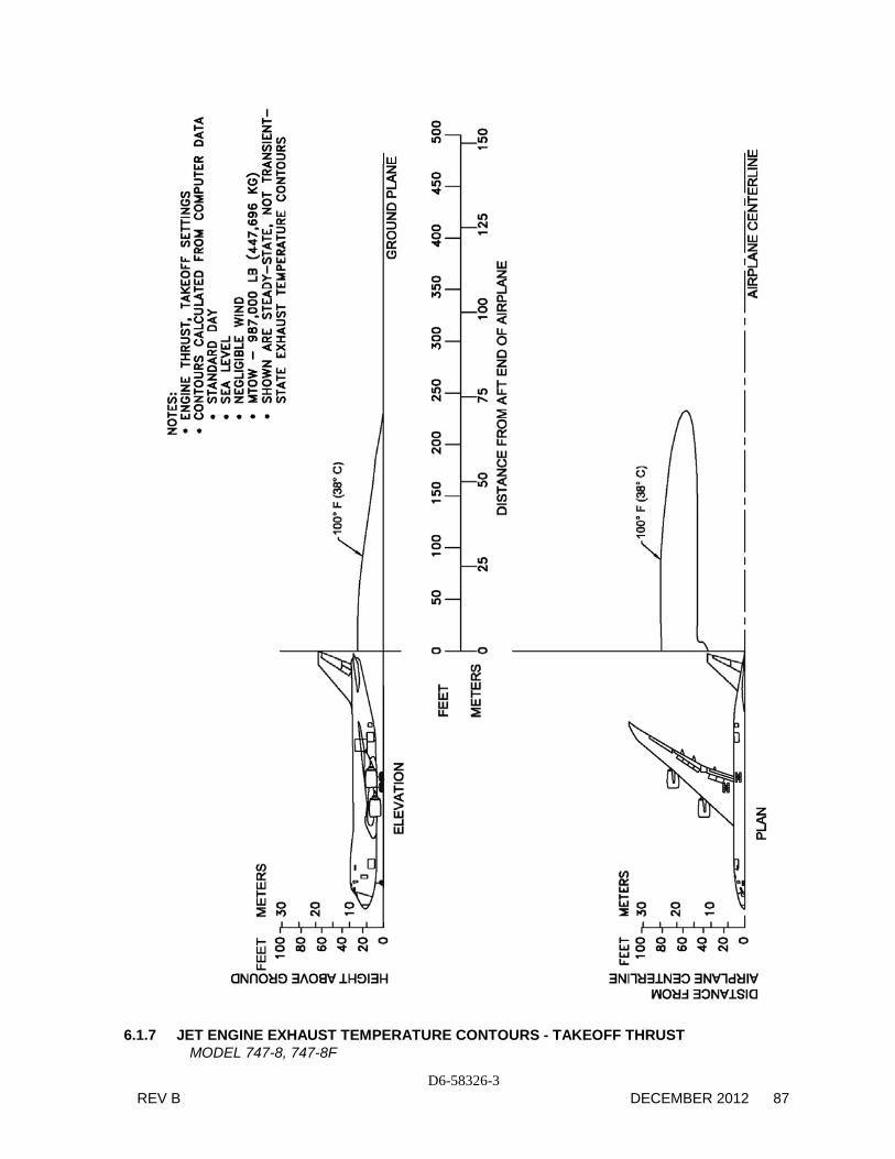
6.1 Jet Engine Exhaust Velocities and Temperatures
This section shows exhaust velocity and temperature contours aft of the 747-8 and 747-8 Freighter airplanes due to the use of the same engine and same weight for both airplanes. The contours were calculated from a standard computer analysis using three-dimensional viscous flow equations with mixing of primary, fan, and free-stream flow. The presence of the ground plane is included in the calculations. Mixing of flows from the engines is also calculated. The analysis does not include thermal buoyancy effects which tend to elevate the jet wake above the ground plane. The buoyancy effects are considered to be small relative to the exhaust velocity and therefore are not included.
The graphs show jet wake velocity and temperature contours for a representative engine. The results are valid for sea level, static, standard day conditions. The effect of wind on jet wakes was not included. There is evidence to show that a downwind or an upwind component does not simply add or subtract from the jet wake velocity, but rather carries the whole envelope in the direction of the wind. Crosswinds may carry the jet wake contour far to the side at large distances behind the airplane.
The users of these exhaust velocity contour data should understand that these data reflect steady-state at maximum taxi weight and not transient-state exhaust velocities. A steady-state is achieved with the aircraft in a fixed location, engine running at a given thrust level and measured when the contours stop expanding and stabilize in size, which could take several seconds. The steady-state condition, therefore, is conservative. Contours shown also do not account for performance variables such as ambient temperature or field elevation. For the terminal area environment, the transient-state is a more accurate representation of the actual exhaust contours when the aircraft is in motion and encountering static air with forward or turning movement, but it is very difficult to model on a consistent basis due to aircraft weight, weather conditions, the high degree of variability in terminal and apron configurations, and intensive numerical calculations. If the contours presented here are overly restrictive for terminal operations, The Boeing Company recommends conducting an analysis of the actual exhaust contours experienced by the using aircraft at the airport.

D6-58326-3 REV B DECEMBER 2012 81
6.1.1 JET ENGINE EXHAUST VELOCITY CONTOURS – IDLE THRUST MODEL 747-8, 747-8F

D6-58326-3 82 DECEMBER 2012 REV B
6.1.2 JET ENGINE EXHAUST VELOCITY CONTOURS – BREAKAWAY THRUST – LEVEL PAVEMENT
MODEL 747-8, 747-8F

D6-58326-3 REV B DECEMBER 2012 83
6.1.3 JET ENGINE EXHAUST VELOCITY CONTOURS – BREAKAWAY THRUST -
1% PAVEMENT UPSLOPE MODEL 747-8, 747-8F

D6-58326-3 84 DECEMBER 2012 REV B
6.1.4 JET ENGINE EXHAUST VELOCITY CONTOURS - BREAKAWAY THRUST -
1.5% PAVEMENT UPSLOPE MODEL 747-8, 747-8F

D6-58326-3 REV B DECEMBER 2012 85
6.1.5 JET ENGINE EXHAUST VELOCITY CONTOURS - TAKEOFF THRUST
MODEL 747-8, 747-8F

D6-58326-3 86 DECEMBER 2012 REV B
6.1.6 JET ENGINE EXHAUST TEMPERATURE CONTOURS – IDLE AND BREAKAWAY MODEL 747-8, 747-8F
D6-58326-3 REV B DECEMBER 2012 87
6.1.7 JET ENGINE EXHAUST TEMPERATURE CONTOURS - TAKEOFF THRUST
MODEL 747-8, 747-8F

D6-58326-3 88 DECEMBER 2012 REV B
6.2 Airport and Community Noise
Airport noise is of major concern to the airport and community planner. The airport is a major element in the community's transportation system and, as such, is vital to its growth. However, the airport must also be a good neighbor, and this can be accomplished only with proper planning. Since aircraft noise extends beyond the boundaries of the airport, it is vital to consider the impact on surrounding communities. Many means have been devised to provide the planner with a tool to estimate the impact of airport operations. Too often they oversimplify noise to the point where the results become erroneous. Noise is not a simple subject; therefore, there are no simple answers.
The cumulative noise contour is an effective tool. However, care must be exercised to ensure that the contours, used correctly, estimate the noise resulting from aircraft operations conducted at an airport.
The size and shape of the single-event contours, which are inputs into the cumulative noise contours, are dependent upon numerous factors. They include the following:
1. Operational Factors
(a) Aircraft Weight - Aircraft weight is dependent on operating empty weight, distance to be traveled, en route winds, payload, and reserve fuel anticipated from a potential aircraft delay upon reaching the destination.
(b) Engine Power Settings - The rates of ascent and descent and the noise levels emitted at the source are influenced by the power setting used.
(c) Airport Altitude - Higher airport altitude will affect engine performance and thus can influence noise.
2. Atmospheric Conditions-Sound Propagation
(a) Wind - With stronger headwinds, the aircraft can take off and climb more rapidly relative to the ground. Also, winds can influence the distribution of noise in surrounding communities.
(b) Temperature and Relative Humidity - The absorption of noise in the atmosphere along the transmission path between the aircraft and the ground observer varies with both temperature and relative humidity.

D6-58326-3 REV B DECEMBER 2012 89
3. Surface Condition - Shielding, Extra Ground Attenuation (EGA)
(a) Terrain - If the ground slopes down after takeoff or up before landing, noise will be reduced since the aircraft will be at a higher altitude above ground. Additionally, hills, shrubs, trees, and large buildings can act as sound buffers.
All these factors can alter the shape and size of the contours appreciable. To demonstrate the effect of some of these factors, estimated noise level contours for two different operating conditions are shown below. These contours reflect a given noise level upon a ground level plane at runway elevation.
Condition 1
Landing Takeoff
Maximum Design Landing Weight
Maximum Design Takeoff Weight
10-knot Headwind Zero Wind 3o Approach 84 oF (29 oC) 84 oF (29 oC) Humidity 15% Humidity 15%
Condition 2
Landing: Takeoff:
85% of Maximum Design Landing Weight
80% of Maximum Design Takeoff Weight
10-knot Headwind 10-knot Headwind 3o Approach 59 oF (15 oC) 59 oF (15 oC) Humidity 70% Humidity 70%

D6-58326-3 90 DECEMBER 2012 REV B
As indicated from these data, the contour size varies substantially with operating and atmospheric conditions. Most aircraft operations are, of course, conducted at less than maximum gross weights because average flight distances are much shorter than maximum aircraft range capability and average load factors are less than 100%. Therefore, in developing cumulative contours for planning purposes, it is recommended that the airlines serving a particular city be contacted to provide operational information.
In addition, there are no universally accepted methods for developing aircraft noise contours or for relating the acceptability of specific zones to specific land uses. It is therefore expected that noise contour data for particular aircraft and the impact assessment methodology will be changing. To ensure that the best currently available information of this type is used in any planning study, it is recommended that it be obtained directly from the Office of Environmental Quality in the Federal Aviation Administration in Washington, D.C.
It should be noted that the contours shown herein are only for illustrating the impact of operating and atmospheric conditions and do not represent the single-event contour of the family of aircraft described in this document. It is expected that the cumulative contours will be developed as required by planners using the data and methodology applicable to their specific study.

D6-58326-3 REV B DECEMBER 2012 91
7.0 PAVEMENT DATA
7.1 General Information
7.2 Landing Gear Footprint
7.3 Maximum Pavement Loads
7.4 Landing Gear Loading on Pavement
7.5 Flexible Pavement Requirements - U.S. Army Corps of Engineers Method S-77-1
7.6 Flexible Pavement Requirements - LCN Conversion
7.7 Rigid Pavement Requirements - Portland Cement Association Design Method
7.8 Rigid Pavement Requirements - LCN Conversion
7.9 Rigid Pavement Requirements - FAA Design Method
7.10 ACN/PCN Reporting System - Flexible and Rigid Pavements
7.11 Nose Gear Tethering

D6-58326-3 92 DECEMBER 2012 REV B
7.0 PAVEMENT DATA
7.1 General Information
A brief description of the pavement charts that follow will help in their use for airport planning. Each airplane configuration is depicted with a minimum range of six loads imposed on the main landing gear to aid in interpolation between the discrete values shown. All curves for any single chart represent data based on rated loads and tire pressures considered normal and acceptable by current aircraft tire manufacturer's standards. Tire pressures, where specifically designated on tables and charts, are at values obtained under loaded conditions as certificated for commercial use.
Section 7.2 presents basic data on the landing gear footprint configuration, maximum design taxi loads, and tire sizes and pressures.
Maximum pavement loads for certain critical conditions at the tire-to-ground interface are shown in Section 7.3, with the tires having equal loads on the struts.
Pavement requirements for commercial airplanes are customarily derived from the static analysis of loads imposed on the main landing gear struts. The chart in Section 7.4 is provided in order to determine these loads throughout the stability limits of the airplane at rest on the pavement. These main landing gear loads are used as the point of entry to the pavement design charts, interpolating load values where necessary.
The flexible pavement design curves (Section 7.5) are based on procedures set forth in Instruction Report No. S-77-1, "Procedures for Development of CBR Design Curves," dated June 1977, and as modified according to the methods described in ICAO Aerodrome Design Manual, Part 3, Pavements, 2nd Edition, 1983, Section 1.1 (The ACN-PCN Method), and utilizing the alpha factors approved by ICAO in October 2007. Instruction Report No. S-77-1 was prepared by the U.S. Army Corps of Engineers Waterways Experiment Station, Soils and Pavements Laboratory, Vicksburg, Mississippi. The line showing 10,000 coverages is used to calculate Aircraft Classification Number (ACN).
The following procedure is used to develop the curves, such as shown in Section 7.5:
1. Having established the scale for pavement depth at the bottom and the scale for CBR at the top, an arbitrary line is drawn representing 10,000 coverages.
2. Values of the aircraft weights on the main landing gear are then plotted.
3. Additional annual departure lines are drawn based on the load lines of the aircraft gross weights already established.

D6-58326-3 REV B DECEMBER 2012 93
All Load Classification Number (LCN) curves (Sections 7.6 and 7.8) have been developed from a computer program based on data provided in International Civil Aviation Organization (ICAO) document 9157-AN/901, Aerodrome Design Manual, Part 3, "Pavements," Second Edition, 1983. LCN values are shown directly for parameters of weight on main landing gear, tire pressure, and radius of relative stiffness (l) for rigid pavement or pavement thickness or depth factor (h) for flexible pavement.
Rigid pavement design curves (Section 7.7) have been prepared with the Westergaard equation in general accordance with the procedures outlined in the Design of Concrete Airport Pavement (1955 edition) by Robert G. Packard, published by the Portland Cement Association, 3800 North Wilke Road, Arlington Heights, Illinois 60004-1268. These curves are modified to the format described in the Portland Cement Association publication XP6705-2, Computer Program for Airport Pavement Design (Program PDILB), 1968, by Robert G. Packard.
The following procedure is used to develop the rigid pavement design curves shown in Section 7.7:
1. Having established the scale for pavement thickness to the left and the scale for allowable working stress to the right, an arbitrary load line is drawn representing the main landing gear maximum weight to be shown.
2. Values of the subgrade modulus (k) are then plotted.
3. Additional load lines for the incremental values of weight on the main landing gear are drawn on the basis of the curve for k = 300, already established.
For the rigid pavement design (Section 7.9) refer to the FAA website for the FAA design software COMFAA:
http://www.faa.gov/airports/engineering/design_software/

D6-58326-3 94 DECEMBER 2012 REV B
The ACN/PCN system (Section 7.10) as referenced in ICAO Annex 14, “Aerodromes,” Fifth Edition, July 2009, provides a standardized international airplane/pavement rating system replacing the various S, T, TT, LCN, AUW, ISWL, etc., rating systems used throughout the world. ACN is the Aircraft Classification Number and PCN is the Pavement Classification Number. An aircraft having an ACN equal to or less than the PCN can operate on the pavement subject to any limitation on the tire pressure. Numerically, the ACN is twice the derived single-wheel load expressed in thousands of kilograms, where the derived single wheel load is defined as the load on a single tire inflated to 181 psi (1.25 MPa) that would have the same pavement requirements as the aircraft. Computationally, the ACN/PCN system uses the PCA program PDILB for rigid pavements and S-77-1 for flexible pavements to calculate ACN values. The method of pavement evaluation is left up to the airport with the results of their evaluation presented as follows:
PCN PAVEMENT TYPE
SUBGRADE CATEGORY
TIRE PRESSURE CATEGORY
EVALUATION METHOD
R = Rigid A = High W = No Limit T = Technical
F = Flexible B = Medium X = To 254 psi (1.75 MPa) U = Using Aircraft
C = Low Y = To 181 psi (1.25 MPa)
D = Ultra Low Z = To 73 psi (0.5 MPa)
Section 7.10.1 shows the aircraft ACN values for flexible pavements. The four subgrade categories are:
Code A - High Strength - CBR 15 Code B - Medium Strength - CBR 10 Code C - Low Strength - CBR 6 Code D - Ultra Low Strength - CBR 3
Section 7.10.2 shows the aircraft ACN values for rigid pavements. The four subgrade categories are:
Code A - High Strength, k = 550 pci (150 MN/m3) Code B - Medium Strength, k = 300 pci (80 MN/m3) Code C - Low Strength, k = 150 pci (40 MN/m3) Code D - Ultra Low Strength, k = 75 pci (20 MN/m3)

D6-58326-3 REV B DECEMBER 2012 95
NOT TO SCALE UNITS 747-8F 747-8, 747-8F MAXIMUM DESIGN TAXI WEIGHT
LB KG
978,000 443,613
990,000 449,056
PERCENT OF WEIGHT ON MAIN GEAR % SEE SECTION 7.4
NOSE GEAR TIRE SIZE IN. 50 X 20.0 R 22, 26 PR 50 X 20.0 R22, 26 PR NOSE GEAR TIRE PRESSURE
PSI KG/CM2
167 11.74
167 11.74
MAIN GEAR TIRE SIZE IN. 52 X 21.0 R22, 36 PR 52 X 21.0 R22, 36 PR MAIN GEAR TIRE PRESSURE
PSI KG/CM2
221 15.54
221 15.54
7.2 LANDING GEAR FOOTPRINT MODEL 747-8, 747-8F

D6-58326-3 96 DECEMBER 2012 REV B
V NG = MAXIMUM VERTICAL NOSE GEAR GROUND LOAD AT MOST FORWARD CENTER OF GRAVITY V MG = MAXIMUM VERTICAL MAIN GEAR GROUND LOAD AT MOST AFT CENTER OF GRAVITY H = MAXIMUM HORIZONTAL GROUND LOAD FROM BRAKING
NOTE: ALL LOADS CALCULATED USING AIRPLANE MAXIMUM DESIGN TAXI WEIGHT
VNG
VMG PER STRUT (4)
H PER STRUT (4)
MAX STATIC STATIC + MAX STEADY AT AIRPLANE UNITS DESIGN AT BRAKING LOAD AT BRAKING INSTANTANEOUS
MODEL TAXI MOST 10 FT/SEC2 STATIC 10 FT/SEC2 BRAKING WEIGHT FWD C.G. DECEL AFT C.G. DECEL (m = 0.8)
747-8 LB 990,000 70,112 119,606 234,348 76,874 187,478 KG 449,056 31,802 54,252 106,299 34,870 85,039
747-8F LB 978,000 65,145 116,380 231,507 75,942 185,206 KG 443,613 29,549 52,789 105,010 34,447 84,008
747-8F LB 990,000 70,112 119,606 234,515 76,874 186,812 KG 449,056 31,802 54,252 105,921 34,870 84,736 7.3. MAXIMUM PAVEMENT LOADS
MODEL 747-8, 747-8F
H VNG
V V V V
VMG VMG VMG H

D6-58326-3 REV B DECEMBER 2012 97
7.4.1 LANDING GEAR LOADING ON PAVEMENT MODEL 747-8 (990,000 LB, 449,056 KG)

D6-58326-3 98 DECEMBER 2012 REV B
7.4.2 LANDING GEAR LOADING ON PAVEMENT MODEL 747-8F (978,000 LB, 443,613 KG)

D6-58326-3 REV B DECEMBER 2012 99
7.4.3 LANDING GEAR LOADING ON PAVEMENT MODEL 747-8F (990,000 LB, 449,056 KG)

D6-58326-3 100 DECEMBER 2012 REV B
7.5 Flexible Pavement Requirements - U.S. Army Corps of Engineers Method (S-77-1)
The following flexible-pavement design chart presents the data of six incremental main-gear loads at the minimum tire pressure required at the maximum design taxi weight.
In the examples shown in Section 7.5.1 and 7.5.2, for a CBR of 30 and an annual departure level of 15,000, the required flexible pavement thickness for an airplane with a main gear loading of 800,000 pounds (362,874 kg) is 12.5 inches (31.8 cm).
The line showing 10,000 coverages is used for ACN calculations (see Section 7.10).
The FAA design method uses a similar procedure using total airplane weight instead of weight on the main landing gears. The equivalent main gear loads for a given airplane weight could be calculated from Section 7.4.

D6-58326-3 REV B DECEMBER 2012 101
7.5.1 FLEXIBLE PAVEMENT REQUIREMENTS - U.S. ARMY CORPS OF ENGINEERS DESIGN METHOD (S-77-1)
MODEL 747-8F (978,000 LB, 443,613 KG)

D6-58326-3 102 DECEMBER 2012 REV B
7.5.2 FLEXIBLE PAVEMENT REQUIREMENTS - U.S. ARMY CORPS OF ENGINEERS DESIGN METHOD (S-77-1)
MODEL 747-8, 747-8F (990,000 LB, 449,056 KG)

D6-58326-3 REV B DECEMBER 2012 103
7.6 Flexible Pavement Requirements - LCN Method
To determine the airplane weight that can be accommodated on a particular flexible pavement, both the Load Classification Number (LCN) of the pavement and the thickness must be known.
In the example shown in Section 7.6.1 and 7.6.2, flexible pavement thickness is shown at 32 in (81 cm). with an LCN of 92. For these conditions, the apparent maximum allowable weight permissible on the main landing gear is 600,000 lb (272,155 kg) for an airplane with 221-psi (15.54 kg/cm2) main gear tires.
Note: If the resultant aircraft LCN is not more that 10% above the published pavement LCN, the bearing strength of the pavement can be considered sufficient for unlimited use by the airplane. The figure 10% has been chosen as representing the lowest degree of variation in LCN that is significant (reference: ICAO Aerodrome Design Manual, Part 2, "Aerodrome Physical Characteristics,” Chapter 4, Paragraph 4.1.5.7v, 2nd Edition dated 1965).

D6-58326-3 104 DECEMBER 2012 REV B
7.6.1 FLEXIBLE PAVEMENT REQUIREMENTS - LCN METHOD MODEL 747-8F (978,000 LB, 443,613 KG)

D6-58326-3 REV B DECEMBER 2012 105
7.6.2 FLEXIBLE PAVEMENT REQUIREMENTS - LCN METHOD MODEL 747-8, 747-8F (990,000 LB, 449,056 KG)

D6-58326-3 106 DECEMBER 2012 REV B
7.7 Rigid Pavement Requirements - Portland Cement Association Design Method
The Portland Cement Association method of calculating rigid pavement requirements is based on the computerized version of "Design of Concrete Airport Pavement" (Portland Cement Association, 1965) as described in XP6705-2, "Computer Program for Airport Pavement Design" by Robert G. Packard, Portland Cement Association, 1968.
The rigid pavement design charts in Section 7.7.1 and 7.7.2, present the data for six incremental main gear loads at the minimum tire pressure required at the maximum design taxi weight.
In the example shown, for an allowable working stress of 550 psi (38.67 kg/cm2), a main gear load of 800,000 lb (362,874 kg), and a subgrade strength (k) of 300, the required rigid pavement thickness is 10.6 in (26.9 cm).

D6-58326-3 REV B DECEMBER 2012 107
ALL
OW
AB
LE W
OR
KIN
G S
TRES
S
PSI
KG
/SQ
CM
CE
NTI
MET
ERS
INC
HES
PA
VE
ME
NT
THIC
KNES
S
7.7.1 RIGID PAVEMENT REQUIREMENTS - PORTLAND CEMENT ASSOCIATION DESIGN METHOD
MODEL 747-8F (978,000 LB, 443,613 KG)

D6-58326-3 108 DECEMBER 2012 REV B
ALL
OW
ABLE
WO
RKI
NG
STR
ESS
ALL
OW
ABLE
WO
RKI
NG
STR
ESS
ALL
OW
ABLE
WO
RKI
NG
STR
ESS
ALL
OW
ABLE
WO
RKI
NG
STR
ESS
ALL
OW
ABLE
WO
RKI
NG
STR
ESS
PSI
PSI
PSI
PSI
PSI
KG
/SQ
CM
KG
/SQ
CM
KG
/SQ
CM
KG
/SQ
CM
KG
/SQ
CM
CEN
TIM
ETE
RS
CEN
TIM
ETE
RS
CEN
TIM
ETE
RS
CEN
TIM
ETE
RS
CEN
TIM
ETE
RS
INC
HES
INC
HES
INC
HES
INC
HES
INC
HES
PAV
EMEN
T TH
ICKN
ESS
PAV
EMEN
T TH
ICKN
ESS
PAV
EMEN
T TH
ICKN
ESS
PAV
EMEN
T TH
ICKN
ESS
PAV
EMEN
T TH
ICKN
ESS
7.7.2 RIGID PAVEMENT REQUIREMENTS - PORTLAND CEMENT ASSOCIATION DESIGN METHOD
MODEL 747-8, 747-8F (990,000 LB, 449,056 KG)

D6-58326-3 REV B DECEMBER 2012 109
7.8 Rigid Pavement Requirements - LCN Conversion
To determine the airplane weight that can be accommodated on a particular rigid pavement, both the LCN of the pavement and the radius of relative stiffness (l) of the pavement must be known.
In the examples shown in Section 7.8.2 for a rigid pavement with a radius of relative stiffness of 47 with an LCN of 91, and 7.8.3 for a rigid pavement with a radius of relative stiffness of 47 with an LCN of 87, the apparent maximum allowable weight permissible on the main landing gear is 600,000 lb (272,155 kg) for an airplane with 221-psi (15.54 kg/cm2) main tires.
Note: If the resultant aircraft LCN is not more that 10% above the published pavement LCN, the bearing strength of the pavement can be considered sufficient for unlimited use by the airplane. The figure 10% has been chosen as representing the lowest degree of variation in LCN that is significant (reference: ICAO Aerodrome Design Manual, Part 2, "Aerodrome Physical Characteristics,” Chapter 4, Paragraph 4.1.5.7v, 2nd Edition dated 1965).

D6-58326-3 110 DECEMBER 2012 REV B
RADIUS OF RELATIVE STIFFNESS (l)
VALUES IN INCHES
l = 4 Ed3
12(1-µ2)k = 24.1652
4 d3k
WHERE: E = YOUNG'S MODULUS OF ELASTICITY = 4 x 10⁶ psi
k = SUBGRADE MODULUS, LB PER CU IN d = RIGID PAVEMENT THICKNESS, IN
µ = POISSON'S RATIO = 0.15
k = k = k = k = k = k = k = k = k = k = d 75 100 150 200 250 300 350 400 500 550
6.0 31.48 29.29 26.47 24.63 23.30 22.26 21.42 20.71 19.59 19.13 6.5 33.42 31.10 28.11 26.16 24.74 23.63 22.74 21.99 20.80 20.31 7.0 35.33 32.88 29.71 27.65 26.15 24.99 24.04 23.25 21.99 21.47 7.5 37.21 34.63 31.29 29.12 27.54 26.31 25.32 24.49 23.16 22.61 8.0 39.06 36.35 32.84 30.56 28.91 27.62 26.57 25.70 24.31 23.73 8.5 40.87 38.04 34.37 31.99 30.25 28.90 27.81 26.90 25.44 24.84 9.0 42.66 39.70 35.88 33.39 31.57 30.17 29.03 28.07 26.55 25.93 9.5 44.43 41.35 37.36 34.77 32.88 31.42 30.23 29.24 27.65 27.00 10.0 46.17 42.97 38.83 36.13 34.17 32.65 31.41 30.38 28.73 28.06 10.5 47.89 44.57 40.27 37.48 35.44 33.87 32.58 31.52 29.81 29.10 11.0 49.59 46.15 41.70 38.81 36.70 35.07 33.74 32.63 30.86 30.14 11.5 51.27 47.72 43.12 40.12 37.95 36.26 34.89 33.74 31.91 31.16 12.0 52.94 49.26 44.51 41.43 39.18 37.43 36.02 34.83 32.94 32.17 12.5 54.58 50.80 45.90 42.71 40.40 38.60 37.14 35.92 33.97 33.17 13.0 56.21 52.31 47.27 43.99 41.60 39.75 38.25 36.99 34.98 34.16 13.5 57.83 53.81 48.63 45.25 42.80 40.89 39.34 38.05 35.99 35.14 14.0 59.43 55.30 49.97 46.50 43.98 42.02 40.43 39.10 36.98 36.11 14.5 61.01 56.78 51.30 47.74 45.15 43.14 41.51 40.15 37.97 37.07 15.0 62.58 58.24 52.62 48.97 46.32 44.25 42.58 41.18 38.95 38.03 15.5 64.14 59.69 53.93 50.19 47.47 45.35 43.64 42.21 39.92 38.98 16.0 65.69 61.13 55.23 51.40 48.61 46.45 44.69 43.22 40.88 39.92 16.5 67.22 62.55 56.52 52.60 49.75 47.53 45.73 44.23 41.83 40.85 17.0 68.74 63.97 57.80 53.79 50.87 48.61 46.77 45.23 42.78 41.77 17.5 70.25 65.38 59.07 54.97 51.99 49.68 47.80 46.23 43.72 42.69 18.0 71.75 66.77 60.34 56.15 53.10 50.74 48.82 47.22 44.65 43.60 19.0 74.72 69.54 62.83 58.47 55.30 52.84 50.84 49.17 46.50 45.41 20.0 77.65 72.26 65.30 60.77 57.47 54.91 52.83 51.10 48.33 47.19 21.0 80.55 74.96 67.73 63.03 59.61 56.95 54.80 53.00 50.13 48.95 22.0 83.41 77.62 70.14 65.27 61.73 58.98 56.75 54.88 51.91 50.68 23.0 86.23 80.25 72.51 67.48 63.82 60.98 58.67 56.74 53.67 52.40 24.0 89.03 82.85 74.86 69.67 65.89 62.95 60.57 58.58 55.41 54.10 25.0 91.80 85.43 77.19 71.84 67.94 64.91 62.46 60.41 57.13 55.78
7.8.1 RADIUS OF RELATIVE STIFFNESS (REFERENCE: PORTLAND CEMENT ASSOCIATION)

D6-58326-3 REV B DECEMBER 2012 111
7.8.2 RIGID PAVEMENT REQUIREMENTS - LCN CONVERSION MODEL 747-8F (978,000 LB, 443,613 KG)

D6-58326-3 112 DECEMBER 2012 REV B
7.8.3 RIGID PAVEMENT REQUIREMENTS - LCN CONVERSION MODEL 747-8, 747-8F (990,000 LB, 449,056 KG)

D6-58326-3 REV B DECEMBER 2012 113
7.9 Rigid Pavement Requirements - FAA Design Method
For the rigid pavement design, refer to the FAA website for the FAA design software COMFAA:
http://www.faa.gov/airports/engineering/design_software/

D6-58326-3 114 DECEMBER 2012 REV B
7.10 ACN/PCN Reporting System: Flexible and Rigid Pavements
To determine the ACN of an aircraft on flexible or rigid pavement, both the aircraft gross weight and the subgrade strength category must be known. In the chart in Section 7.10.1 and 7.10.3, for an aircraft with gross weight of 900,000 lb (408,233 kg) and medium subgrade strength, the flexible pavement ACN is 62. In Section 7.10.2 and 7.10.4, for the same gross weight and subgrade strength, the rigid pavement ACN is 67.
The following table provides ACN data in tabular format similar to the one used by ICAO in the “Aerodrome Design Manual Part 3, Pavements”. If the ACN for an intermediate weight between maximum taxi weight and the empty weight of the aircraft is required, Figures 7.10.1 through 7.10.4 should be consulted.
ACN FOR RIGID PAVEMENT SUBGRADES – MN/m3
ACN FOR FLEXIBLE PAVEMENT SUBGRADES – CBR
AIRCRAFT TYPE
MAXIMUM TAXI
WEIGHT
MINIMUM WEIGHT (1)
LB (KG)
LOAD ON
ONE MAIN GEAR LEG (%)
TIRE
PRESSURE
PSI (MPa)
HIGH 150
MEDIUM 80
LOW 40
ULTRALOW
20
HIGH 15
MEDIUM 10
LOW 6
ULTRALOW
3
747-8F 978,000
(443,613)
500,000
(226,796)
23.67 221 (1.52) 64
27
75
30
88
35
101
41
63
27
70
28
87
32
110
43
747-8F
990,000
(449,056)
500,000
(226,796)
23.59 221 (1.52) 65
27
76
30
90
35
102
41
63
27
70
28
88
32
111
43
747-8
990,000
(449,056)
500,000
(226,796)
23.67 221 (1.52) 65
27
77
30
90
35
102
41
63
27
71
28
88
32
112
43
(1) Minimum weight used solely as a baseline for ACN curve generation.

D6-58326-3 REV B DECEMBER 2012 115
7.10.1 AIRCRAFT CLASSIFICATION NUMBER - FLEXIBLE PAVEMENT MODEL 747-8F (978,000 LB, 443,613 KG)

D6-58326-3 116 DECEMBER 2012 REV B
7.10.2 AIRCRAFT CLASSIFICATION NUMBER - RIGID PAVEMENT MODEL 747-8F (978,000 LB, 443,613 KG)

D6-58326-3 REV B DECEMBER 2012 117
7.10.3 AIRCRAFT CLASSIFICATION NUMBER - FLEXIBLE PAVEMENT MODEL 747-8 and 747-8F (990,000 LB, 449,056 KG)

D6-58326-3 118 DECEMBER 2012 REV B
7.10.4 AIRCRAFT CLASSIFICATION NUMBER - RIGID PAVEMENT MODEL 747-8 and 747-8F (990,000 LB, 449,056 KG)

D6-58326-3 REV B DECEMBER 2012 119
7.11 Nose Gear Tethering (Optional)
There are two typical methods used to provide support to prevent airplane tipping during ramp operations. During use of a tail stanchion, pavement strength is considered sufficient and there should be no additional requirements.
The alternate method of tethering the nose landing gear may also be used. Boeing does not have a tool design for straps to tether the airplane. Figure 7.11.1 is provided to supply load conditions sufficient to design and/or verify ramp strength is adequate for this purpose.
7.11.1 NOSE GEAR TETHERING (OPTIONAL)
MODEL 747-8 (990,000 LB, 449,056 KG)

D6-58326-3 120 DECEMBER 2012 REV B
THIS PAGE INTENTIONALLY LEFT BLANK

D6-58326-3 REV B DECEMBER 2012 121
8.0 FUTURE 747-8 DERIVATIVE AIRPLANES

D6-58326-3 122 DECEMBER 2012 REV B
8.0 FUTURE 747-8 DERIVATIVE AIRPLANES
As with most Boeing airplane programs, derivative models are typically being studied to provide additional capabilities of the 747-8 family of airplanes. Future growth versions could address additional passenger count, cargo capacity, increased range, or environmental performance.
Whether and/or when these or other possibilities are actually built is entirely dependent on future airline requirements. In any event, the impact on airport facilities will be a consideration in configuration and design.

D6-58326-3 REV B DECEMBER 2012 123
9.0 SCALED 747-8 DRAWINGS
9.1 747-8, 747-8F

D6-58326-3 124 DECEMBER 2012 REV B
9.0 SCALED DRAWINGS
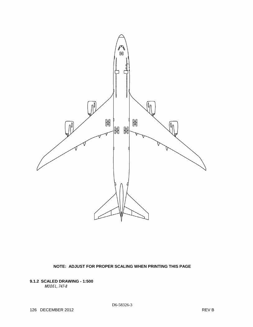
The drawings in the following pages show airplane plan view drawings, drawn to approximate scale as noted. The drawings may not come out to exact scale when printed or copied from this document. Printing scale should be adjusted when attempting to reproduce these drawings. Three-view drawing files of the 747-8, along with other Boeing airplane models, may be downloaded from the following website:
http://www.boeing.com/airports

D6-58326-3 REV B DECEMBER 2012 125
NOTE: ADJUST FOR PROPER SCALING WHEN PRINTING THIS PAGE
9.1.1 SCALED DRAWING - 1:500
MODEL, 747-8F
D6-58326-3 126 DECEMBER 2012 REV B
NOTE: ADJUST FOR PROPER SCALING WHEN PRINTING THIS PAGE 9.1.2 SCALED DRAWING - 1:500
MODEL, 747-8