74-2574 - q9200a1002 openlink controller · system into the honeywell excel 5000 system®. equipped...
TRANSCRIPT

U.S. Registered TrademarkCopyright © 2000 Honeywell Inc. • All rights Reserved
74-2574-1
Q9200A1002OpenLink Controller
FOR HONEYWELL Q7700 BURNER/BOILER & SYSNET SUB-NETWORKSBCS 7700
S7830 RM7800
ARMSTRONG TRAPSCAN SERIES 2000 PULSAFEEDER PULSATROL SERIES 300
DATA ACQUISITION MODULESCLEAVER BROOKS HAWKEYE
SYSTEM ENGINEERING
WARNINGThis equipment generates, uses, and can radiate radio frequency energy, and if not installed and used in accordance withthe Instructions Manual, may cause interference with radio communication. It has been tested and found to comply with thelimits for a Class A computing device pursuant to Subpart J of Part 15 of FCC Rules, which are designed to providereasonable protection against such interference when operated in a commercial environment. Operation of this equipmentin a residential area is likely to cause interference, in which case, users at their own expense will be required to takewhatever measures may be required to correct the interference. Any unauthorized modification of this equipment mayresult in the revocation of the owner's authority to continue its operation.

74-2574-1 2
Contents
INTRODUCTION .............................................................................................................................3
System Overview .........................................................................................................................................................3
Applicable Literature ...................................................................................................................................................5
APPLICATION STEPS ....................................................................................................................6
Application Notes.........................................................................................................................................................6General Notes.............................................................................................................................................................6OpenLink Controller CPU / CARE Tool Notes............................................................................................................7Q7700 Sub-Network / ZM5002 Tool Notes.................................................................................................................8OpenLink Performance...............................................................................................................................................9OpenLink Alarm Notes................................................................................................................................................9
Step 1– Plan the System............................................................................................................................................10Develop Controllers/Points Summary Lists ..............................................................................................................11Q7700 Controller.......................................................................................................................................................11BCS7700 Controller ..................................................................................................................................................13RM 7800 Controller...................................................................................................................................................19S7830 Annunciator ...................................................................................................................................................23Armstrong TRAPSCAN Trap Monitoring System .....................................................................................................24ADAM DATA ACQUISITION MODULES..................................................................................................................25PulsaFeeder PULSATROL Series 300.....................................................................................................................28Cleaver Brooks Hawkeye..........................................................................................................................................38Determine the Number of OpenLink Controllers Required.......................................................................................44Plan the Controller Bus Architecture.........................................................................................................................44
Step 2: Order Hardware and Software .....................................................................................................................47Hardware ..................................................................................................................................................................47Software....................................................................................................................................................................48
Step 3: Configure the OpenLink Controller.............................................................................................................48CARE Configuration (CPU) ......................................................................................................................................48ZM5002 Configuration (OpenLink Controller Configuration Files)............................................................................50

3 74-2574-1
INTRODUCTION
The Q9200A1002 OpenLink Controller is an application level integrator that interfaces the Honeywell Q7700 Burner Boilersystem into the Honeywell Excel 5000 System®. Equipped with a Q7700 interface, an OpenLink Controller provides controland/or monitoring of controller points for the various Burner Boiler controllers.
For the Q7700 system:
• Q7700• BCS 7700• RM7800• S7830• CLEAVER BROOKS HAWKEYE
This guide provides information for the interface to the Q7700 sub-network only. It is not applicable to any other vendornetwork interfaces.
This guide does not contain information on installing, configuring or operating Q7700 or other Burner/Boiler Systems. Itassumes the user is already familiar with those systems and has the Q7700 software as well as the necessary installation,operation, and maintenance manuals.
System Overview
The OpenLink Controller appears on the C-Bus network as any other Excel 500 controller (rev 1.2), and occupies one of thestandard 30 nodes. The OpenLink Controller's CPU (motherboard) is configured using the standard Excel CAREEngineering Tool, and supports the same features as other C-Bus controllers, including Schematics, Control Strategy, andSwitching Logic. A maximum of 768 CARE points (user addresses) can be configured in the OpenLink CPU.
The Q7700 network is connected to the OpenLink Controller's Sub-Network Daughterboard (also called the Vendor NetworkInterface or VNI board). The Honeywell Burner/Boiler controllers communicate with the OpenLink through the Q7700Controller only, no direct connection to individual BCS7700s, etc. Is allowed. The sub-network controllers and their pointsare defined using the ZM5002 OpenLink Configuration Tool. The OpenLink Controller can support up to 10 Q7700controllers on the same RS485 bus. Each Q7700 may have several subbusses per the application.
The OpenLink Controller allows point data to be mapped between the C-Bus network and the Q7700 network. This isaccomplished using the ZM5002 OpenLink Configuration Tool. Once a Q7700 point is mapped to a C-Bus point, that C-Buspoint is the same as any other C-Bus point, and it can be accessed by any C-Bus operator terminal or controller. If a point iscommandable in the Q7700 network, then its corresponding mapped C-Bus point can be commanded (set to manual mode)on the C-Bus, and that manual value will be written down to the Q7700 point.
The OpenLink Controller has three communication ports: screw terminals for RS485 C-Bus network wiring, screw terminalsfor RS485 Q7700 MicroTech network wiring, and an RS232 B-port used for communication to operator terminals anddownloading the configurations.

74-2574-1 4
XBS
Vendor BusRS485
VNI
Q9200
Q7700CommunicationInterface
BCS 7700 Controller or RM7800 Controllerwith S7830 Expanded Annunicator
Up to 5 ControlBusInterfaces are allowed
1 2 3 4 5 6
Q7700CommunicationInterface
BCS 7700 Controller or RM7800 Controllerwith S7830 Expanded Annunicator
1
2 3 4 5 6
CARE & ZM5002Databases aredownloaded through the B-Port
B-Port
The above diagram shows the bus structure of the OpenLink interface. Please note that the Q7700 usesdifferent QS boards in its card cage for each of the interfaced devices. Thus a board in a Q7700 slot for Pulsatrolwill not communicate to a RM7800. Refer to the Burner/Boiler literature for part numbers and usage for QSboards. Each Q7700 attached to the OpenLink must have an address programmed in the QS7850 board whichis physically attached to the OpenLink vendor bus. In systems with a single Q7700, use the default address zero( 0 ), when engineering the system.

5 74-2574-1
Applicable Literature
Table 1 lists available OpenLink Controller literature. The literature is categorized by system component. Use the FormNumber and Title when ordering literature. Obtain the Q7700 literature from the Q7700 representative, it is not availablethrough Honeywell.
Table 1. OpenLink Controller Literature
FormNumber
Title FormNumber
Title
Excel 5000 System: ZM5002 OpenLink Configuration Tool:74-3595 Glossary 74-1836 Specification Sheet74-2930 System Design 74-1848 User Guide74-3958 Control Application Manual 74-1669 ZM5002 Software Release Bulletin74-3553 PC, Monitors, and Printers Specification Data 74-2483 Q7700 Configuration File Software Release
BulletinExcel Building Supervisor System: Q9200A OpenLink Controller:
74-2033 Specification Data 74-1825 Specification Sheet74-3424 Service Data 74-1791 Checkout and Test74-2039 Operator Manual 95-7525 Installation Instructions74-5022 Graphics Operator Manual 74-2483 Q7700 Configuration File Software Release
Bulletin74-3599 Software Release Bulletin 74-1800 Maintenance and Repair
74-1738 Theory of OperationQ7700 Based Burner/BoilerInstallation Manuals & Operation Manuals
74-1668 Motherboard EPROM Software Release Bulletin
65-0105 Honeywell Combustion System Manager 74-2475 Q7700 VNI EPROM Software Release Bulletin63-8316 BCS 7700 Honeywell Boiler Control System66-1046 Boiler Control System 7700 Excel CARE:66-1047 BCS7700 Product Selection Matrix 74-5575- Excel CARE Collation63-2290 BCS7700 Programming 74-5587 Excel CARE User Guide63-2291 BCS7700 Application 74-3596 Excel CARE Software Release Bulletin63-2278 Q7700 Communication Interface Base Unit
Inst.74-5577 Excel CARE Control Icons User Guide
63-2284 QS7700 Control Bus Module Installation63-8331 7800 Series Burner Control Brochure65-0141 7800 Series Feature/Function Summary65-0104 7800 Series Burner Control65-0105 Product Selection Matrix for
RM7800/RM784065-0114 Guide Specification for RM7800/RM784066-2033 S7830 Expanded Annunciator Specification
65-0211 Product Data for Data Acquisition Modules65-0208 Product Data for QS7800C for DAM65-0209 Product Data for QS7800D for Armstrong65-0210 Product Data for QS7800E for Pulsafeeder

74-2574-1 6
APPLICATION STEPS
Step 1: Plan the System
Step 2: Order Hardware and Software
Step 3: Configure the OLink Controller
Application Notes
Before starting to design or configure the OpenLink Controller system, review the following application notes.
General Notes
Note 1: The OpenLink Controller passes the present value of a mapped point from one network to the other. It does nothandle any other information such as point mode (auto/manual), point status (for example, point is in alarm), etc. Ifthe present value of a Q7700 point is such that its corresponding C-Bus point is in alarm, then a typical C-Busalarm is generated.
Note 2: The OpenLink Controller does not report any Q7700 network alarm messages to the C-Bus operator terminals orXBS.
Note 3: The OpenLink Controller motherboard does not support the XDM506 Modem Submodule. On other C-Buscontrollers, this submodule takes the place of the C-Bus network daughterboard and allows the user to dial-indirectly to the controller. If an application requires dial-in access to the OpenLink Controller points, provide anXM100 C-Bus Modem Module. The C-Bus network will then have at least two nodes: the XM100 and the OpenLink.
Note 4: When two points are mapped together, the exchange of present value data is bi-directional. If one pointexperiences a change of present value, that change is written to the other point. If a Q7700 point cannot be writtento (if it is not an AO or DO as listed in the tables in this manual) then the exchange of present value is essentiallyone way, from the Q7700 controller to the OpenLink Controller CPU.
Note 5: When mapping a CARE analog point with float point format to a sub-network analog point with integer format, thevalue going from the C-Bus to the sub-network will be truncated. For example, 75.3 will be truncated to 75.
Note 6: When the OpenLink Controller initializes (after a download), the present value for a pair of mapped points comesfrom the Q7700 point first. The OpenLink reads the sub-network points during the first point scanning cycle (alsoknown as the periodic cycle), before it does any writes to the sub-network. After that, a change of value (analogpoints) or state (digital points) for a point on one network gets written to the point on the other network.
Note 7: There may be up to 30 OpenLink Controllers on a C-Bus network. There may be only one OpenLink Controller ona Q7700 network.
Note 8: An attempt to write to a non-writable Q7700 point results in an Invalid Operation critical alarm on the C-Bus.
Note 9: Point information can be shared from one Q7700 network to another, via the C-Bus, if necessary. A Q7700controller point, mapped up through one OpenLink Controller and passed to another OpenLink Controller using C-Bus globals, can be mapped back down to another Q7700 controller.
Note 10: Flash EPROM is not supported by the OpenLink Controller CPU as it is in other C-Bus controllers. The reason isthat although the CPU configuration (configured by CARE) could be “flashed,” the OpenLink Controllerconfiguration files (configured using the ZM5002 Tool) cannot be flashed. Even if Flash EPROM was supported in

7 74-2574-1
the CPU, a direct connection to the OpenLink Controller would still be required, using the ZM5002 Tool, todownload the OpenLink Controller configuration files.
Note 11: Since the OpenLink Controller has all the programming functionality of the XL500/100/80 controllers, you canimplement OPM Network Control Logic in the OpenLink CARE Control Strategy or Switching Logic.
Note 12: Do not attempt to command a Q7700 point (from a C-bus operator terminal) immediately following the download.The OpenLink cannot perform a write to a sub-network point until it finishes the first periodic cycle (reading all theQ7700 points once). Wait a couple of minutes before attempting to do any point commanding.
Note 13: As with all other C-Bus controllers, make sure the OpenLink Controller has a dedicated transformer.
Note 14: If you map a 2-byte Q7700 point (any point with a span > 255) to a CARE physical point (AI, AO), inaccuratereadings can appear at the C-bus operator interfaces. The point format gets converted in the OpenLink CPU, andloses accuracy. It is recommended that you map all Q7700 2-byte points to CARE pseudo points. See the Q7700controller point tables in this manual.
Note 15: It is recommended that use address 0 if you have only one Q7700 interfaced to the OpenLink. If you will havemultiple Q7700s you will need to change the address in the QS7850 board. Refer to the Burner/Boiler literature forthis process.
Note 16: The SYSNET PC based system may be attached to the Q7700 and will operate as an operator station at that level.The OpenLink will function with the SYSNET system but the performance will be somewhat reduced.
Note 17: The ADAM DAM modules must be programmed with an address prior to installation !!! You should use the PCbased software supplied with SYSNET to do this. You will need a PC with a 232/485 converter to program theADAM modules. You must ground a special pin on the front of the ADAM module for it to accept its address. Referto 65-0211 for this procedure. The ‘point identifier’ you assign to the ADAM will be the address that will be used bythe ZM5002 - just write down what you assigned ( and what module type 4011 , etc. ) before you program throughthe ZM5002 tool.
Note 18: The wiring directions for SYSNET devices are in the 65-xxxx documents listed in the literature table. Pay particularattention to your wire length, as this will determine where resistors must be added. Putting resistors where theydon’t belong will result in a no-response / return condition that can be most annoying.
Note 19: If there is some doubt as to what is or isn’t working on the Q7700 subsystem, obtain a copy of the PC basedSYSNET software and verify if it can read/command points. This is a very user friendly way of debugging theinstallation as it can verify everything except the address on the QS7850 used by the OpenLink.
Note 20: The TRAPSCAN is not intended to be scanned often. A point ‘ScanNow’ must be commanded to 1 to force anupdate. DO NOT continuously command that point as this will substantially affect the lifespan of the TRAPSCANequipment. Once or twice a day is plenty to monitor the steam traps.
OpenLink Controller CPU / CARE Tool Notes
Note 1: Up to 768 points can be configured (attach) in the OpenLink Controller CPU, but no more than 128 of any onepoint type (analog input AI, analog output AO, digital input DI, digital output DO, pseudo analog PA, pseudo digitalPD, remote analog RA, or remote digital RD). Remember that all C-Bus controllers automatically generate thethree PD points Startup, Shutdown, and Executing Stopped.
Note 2: C-Bus global points cannot be directly mapped in the OpenLink Controller CPU to Q7700 controller points. The C-Bus global point must first be converted to a pseudo point. The simplest way to do this is to run the global pointinto an IDT Icon in the CARE Control Strategy, send the IDT output to a pseudo point, and then map the pseudopoint to the Q7700 controller.
Note 3: A Q7700 AI, or AO point may be mapped to a C-Bus AI, AO, or PA point. They can be intermixed, keeping in mindthat the CARE data point attributes are different for the different CARE point types. The present value of the pointpassed from one network to the other is not affected by the analog point type. This may be helpful if a specificapplication involves a large number of one particular analog point type (for example PA's) and has relatively few ofanother type (for example AI's).

74-2574-1 8
Note 4: If there are going to be Time Programs (CARE Daily Programs) in the system, plan how these Time Programs aregoing to affect both networks before performing CARE programming. It is common to have zones or groups of sub-network controllers that share the same Occ/Unocc Schedule. In these cases, one CARE Daily Program thatcommands multiple Occ/Unocc points may suffice for that zone or group. There is a maximum of 20 TimePrograms in the OpenLink Controller (this is the same as any other C-Bus controller). It is also common to sharethis same Occ/Unocc information among C-Bus controllers. In this case, C-Bus global points must be programmedin either the OpenLink Controller CPU, or the other C-Bus controllers, depending on where the point originates andwhere it is going to be received.
Note 5: A C-Bus point can be mapped only to one Q7700 point. One Q7700 point, however, may be mapped to more thanone C-Bus point.
Note 6: When configuring CARE user addresses (C-Bus points), remember the wildcard feature (*) of C-Bus operatorterminals. Establish a naming convention using common prefixes for points, such as by AHU, or Zone, or Q7700controller, etc., that will permit use of the wildcard feature.
Note 7: When configuring CARE user address attributes for analog commandable Q7700 points (AO’s), make sure thehigh/low limits for the CARE point match those in the Q7700 controller tables in this manual. For physical useraddresses, these limits are the 0 and 10V bounds of the I/O Characteristic. For pseudo points, it is the alarm limits.This is important because these high/low limits are the “clipping” values that protect the Q7700 controller fromreceiving a commanded value out of range. If there are Q7700 commandable points for which it is critical that theynot be commanded outside certain limits, it is safer to map those to CARE physicals because the I/O Characteristiclimits are not adjustable on line, as the pseudo point analog alarm limits are. If a user widens the alarm limits (online) for a pseudo point outside of the limits shown for that point in the tables in this manual, they will be able tocommand the point outside of the recommended Q7700 range.
Note 8: Use the Q7700 controller point tables in this manual when configuring the OpenLink CARE application. Most of theQ7700 analog points should be CARE pseudo analogs, because then you do not have to create custom I/OCharacteristics. If you reach the limit of 128 pseudo analogs and want to map more analog points in yourOpenLink, you have to make custom I/O Characteristics to cover your Q7700 point spans. Make CARE I/OCharacteristics for your most common Q7700 point range (for example, 0-255 if there are a lot of those) and mapto those.
Note 9: Q7700 output (AO and DO) points, as shown in the Q7700 controller point tables, are commandable from the C-Bus network. You may command them directly from a C-Bus operators terminal, or command them from ControlStrategy or Switching Logic control sequences programmed in CARE and resident in the OpenLink CPU. Each jobwill have a different sequence of operation, and such programming is up to the field application engineer.
Note 10: A Q7700 point (an AO or DO) that is written to automatically from Control Strategy or Switching Logic routines, willprobably never be read from the Q7700 network, because every time the point is processed by the OpenLink,RACL has set it to be written. If you need positive feedback of that type of Q7700 point value in the OpenLink CPU,create another point in CARE, with a similar user address, and map that point to the same Q7700 point. You canmap one Q7700 point to more than one CARE point.
Note 11: CARE analog input point alarm limits have fixed a “in alar hysterisis. For a linear input I/OCharacteristic, the hysterisis.077V relative to the 0-11V input range or 0.7%. If you make a custom I/OCharacteristic to match a Q7700 point that has a large value high/low span, you may have to get large point valuechanges before the point will go into or out of alarm on the C-Bus. For example: You make a custom I/OCharacteristic for a Q7700 point that has a span of minus 100 to 255 (a difference of 355). How much would theQ7700 point value have to change in order to cause the C-Bus point to return to normal after going into alarm(Hx)? The answer is 0.7% of 355, or 2.48. This is an acceptable amount, but you can see that if the Q7700 pointhad a larger span, the alarming hysterisis could be too large.
Q7700 Sub-Network / ZM5002 Tool Notes
Note 1: If a Honeywell Burner Boiler controller has a power failure, the controller may reset its points to default values. Ifthese points are mapped to C-Bus points, the default values will be read back into the corresponding C-Bus points.
Note 2: Only the Q7700 points specified as outputs (AO and DO) in the Q7700 controller tables in this manual can bewritten to or from the C-Bus network (i.e., those points that can be set to a manual value at a C-Bus operatorterminal or written to automatically by CARE Control Strategy or Switching Logic). The inputs points cannot.

9 74-2574-1
OpenLink Performance
The OpenLink Controller performance in terms of reading and writing points to and from the Q7700 Sub-Network can bedescribed as follows.
The OpenLink reads (or writes, if the point is defined as one to be written) mapped Sub-Network points in a round robinfashion. The OpenLink does nothing with unmapped Q7700 controller points. An OpenLink periodic cycle involves reading(or writing) a point on one controller, then reading (or writing) a point on the next controller, then reading (or writing) a pointon the next controller, and so on until all the points in all the controllers have been read (or written).
The OpenLink writes to a Q7700 point, instead of reading it, when the point “write bit” is set. A point write bit is set when youmanually command the point from C-Bus or the point is commanded automatically from Control Strategy or Switching Logic.This write bit is cleared after the write goes out, and then the point can be read. When a point is commanded automaticallyfrom Control Strategy or Switching Logic, this bit gets reset every RACL cycle. If the RACL cycle time is less than theOpenLink periodic cycle time, the point will always have its write bit set and will never be read.
If the OpenLink Controller is directly connected, through a Q7700, to one controller, the rate at which that controller’s pointsare read or written (as measured using simulators) is listed in the table below. If you have 500 mapped points, it should takethe OpenLink about 500 or more seconds to read or write all the points.
HBCS Controller Type Seconds toscan one point
Q7700 1BCS7700 3RM7800 1S7830 1
Important
The periodic cycle scan rate is slowed down significantly by points in “no response.” If a point does not respondwhen the OpenLink tries to read or write it, the OpenLink will try again (up to four times) before it goes on to thenext point on the next controller. The OpenLink Controller waits for the amount of time as configured in theZM5002 Setup string for each point response.
The OpenLink B-Port communication is very very slow when the OpenLink is connected to the C-Bus. Do notpermanently install a portable operator device on the OpenLink .
OpenLink Alarm Notes
NOTE 1: The following alarms are neither sub-network point nor controller-specific, but deal with the status of the OpenLinkitself:
Alarm Text: Return to normal.Condition: Alarm has returned to normal state.
Alarm Text: Link Comm DownCondition: VNI Communication is disabled, due to—missing sub-module (no board detected by mainboard)—Motherboard/VNI communication is bad (board is present, but no messages are ever transmitted)
Alarm Text: SSI Interface UpCondition: VNI Communication is enabled.
Alarm Text: Download SSI NowCondition: The Excel core database has been successfully downloaded, but not the ZM5002 database.
Alarm Text: Download CPU NowCondition: The ZM5002 database has been successfully downloaded, but not the Excel core database.

74-2574-1 10
Alarm Text: SSI Points ActiveCondition: Both the Excel core and ZM5002 databases have been downloaded. The OpenLink is up and running. Ifyou are not sure of the OpenLink status, cycle power and look for this alarm.
NOTE 2: Sub-Network point specific alarms:
The actual MA Index of the CARE point (found in the CARE Data Point Editor) is encoded in the last two (2) of thethree (3) parameters displayed with alarm messages associated with specific points. Once the CARE point isidentified, check the ZM5002 mapping table to find the associated sub-network point.
par_1 = 0.par_2 = 0, 1 or 2par_3 = 0-255
MA Index = (par_2 X 256) + par_3
For example, if the point associated with MA Index 600 was not present on the sub-network, the alarm messagedisplayed at the C-Bus user interface would be:
UNKNOWN DATA POINT 0 2 88
meaning that the sub-network point mapped to MA Index 600 ((2 X 256) + 88), was not found on the sub-network.
Alarm Text: Link Config Bad par_1 par_2 par_3Condition: A bad mapping, due to:—the OpenLink asked for a point in a format (byte, word, float,..) not supported by the sub-network.—the OpenLink asked for a point type (AI, AO, DI, ...) inconsistent with the point address on the sub-network.
Alarm Text: Unknown Data Point par_1 par_2 par_3Condition: a sub-network point was not found on the sub-network.
Alarm Text: Link Point Alarm par_1 par_2 par_3Condition: a sub-network point is not responding. (In the case of an analog point, the corresponding CARE pointwill read a value of -99 when the sub-network point is not responding).
If you are repeatedly getting this alarm, followed by a return to normal on the same point, increase the “Pointno Response” time in the ZM5002 Setup field and download again.
Alarm Text: Invalid Operation par_1 par_2 par_3Condition: an attempt is made to write a Non-commandable sub-network point.
NOTE 3: Controller-Specific Alarms
The controller index number is encoded in the first of the three (3) parameters passed with alarm messagesassociated with specific controllers. The user has to consult the olink.map text file in the ZM5002 directory (createdduring download) to determine the controller.
par_1 = Index of Controller (0-253) in the olink.map text file in the ZM5002 directory.par_2 = 0par_3 = 0
Alarm Text: CPU Not Available par_1 par_2 par_3Condition: Sub-network controller is not responding (all of its mapped points are in “no response”). The CPU NotAvailable alarm will Return to Normal when one point in that controller is no longer in “no response”. See Setup inthe ZM5002 Configuration section of this manual for further details.
Step 1– Plan the System
Review all Application Notes before starting to design or configure the OpenLink Controller system.
Complete system planning by:

11 74-2574-1
1. Developing summary lists of controllers and points.
2. Determining the number of OpenLink Controllers required in the system.
3. Planning the controller bus architecture.
Develop Controllers/Points Summary Lists
Accurate controller I/O summaries will help with system configuration and simplify both installation and checkout.
Note: The fewer Burner/Boiler points, per Q7700 controller, that the customer has to access from C-Bus, the moreQ7700 controllers can be supported by a single OpenLink Controller. Even though one OpenLink Controller cantheoretically support up to 10 Q7700 controllers, the CPU limitation on the number of points (128 of any one pointtype or 768 total points) will probably be the governing factor.
List the Q7700, RM7800, BCS7700 Controllers and Points
If not already available, assemble an I/O summary for each of the Burner/Boiler controllers containing all the points to bemapped to the C-Bus. This list will be necessary when performing the CARE and ZM5002 configurations. Burner/Boilercontroller points that do not need to be accessed on the C-Bus do not need to be included in this list.
In the I/O Summary, include the Q7700 controller type and sub-network node number; name each Q7700 controller. Foreach point on the list, include the point type.
If you are sharing data among other C-Bus controllers or are going to be doing any Control Strategy or Switching Logic inthe OpenLink CPU, include all global and/or pseudo points in the I/O Summary.
When assigning CARE user addresses (C-Bus points), remember the wild card feature (*) for viewing points using C-BusPC Tools. Establish a naming convention using common prefixes for points, such as by AHU, or Zone, or Q7700 controller,etc., that will make this feature easy to use. A CARE User Address must not exceed 18 characters.
One CARE plant is going to be configured for each of the Q7700 controllers.
Tables 1 though 19 list the Q7700 controller points that can be mapped to the C-Bus. If you make the CARE Plant UserAddresses read similar to the Description of Point names in the tables, mapping points together in the ZM5002 Tool willbe very easy. Remember the 18-character limitation on CARE user addresses.
Q7700 Controller
The following information is provided from Q7700 documentation. The information is included here to help you understandthe Q7700.
Q7700 ControllerThe Q7700 controller acts as the interface between the Excel 5000 OpenLink and the various Honeywell Burner/Boilercontrollers. The Q7700 contains 6 card slots which can contain the interface drivers for the 7700, 7800 or custom interfacebusses.

74-2574-1 12
Table 1. Q7700 Controller point listPointreferencenumber
Description of point Q7700pointtype
Q7700Eng. unit
Point Values & Definition,or Point Value low range , highrange(use same decimal places forCARE engineering unit)
1 ProgramIdent AI ana 0 02 Slot1NetworkAddr AI ana 0 2553 Slot2NetworkAddr AI ana 0 2554 Slot3NetworkAddr AI ana 0 2555 Slot4NetworkAddr AI ana 0 2556 Slot5NetworkAddr AI ana 0 2557 Slot6NetworkAddr AI ana 0 2558 LocalNetworkAddr AI ana 0 2559 ModemNetworkAddr AI ana 0 25510 CommIntNetworkAddr AI ana 0 25511 InactivityTimeout AO bnk 1 3216712 ResponseTimeout AO bnk 1 3216713 MajorRevision AI bnk 0 9914 MinorRevision AI bnk 0 9915 LocalOnlyReporting AO ind 0 116 LocalDeviceType AO ind 0 217 LocalBaudRate AO ind 0 218 AnswerRings AO cnt 1 719 DialMethod AO ind 0 120 DialOutDelay1 AO min 0 12021 DialOutCease1 AO ind 0 322 DialOutDeviceType1 AO ind 0 223 DialOutBaudRate1 AO ind 0 224 DialOutDelay2 AO min 0 12025 DialOutCease2 AO ind 0 326 DialOutDeviceType2 AO ind 0 227 DialOutBaudRate2 AO ind 0 228 DialOutDelay3 AO min 0 12029 DialOutCease3 AO ind 0 330 DialOutDeviceType3 AO ind 0 231 DialOutBaudRate3 AO ind 0 2

13 74-2574-1
BCS7700 Controller
The following information is provided from BCS7700 documentation. The information is included here to help youunderstand the BCS7700.
BCS7700 Controller
The BCS7700 controller is a boiler control system controller. It is defined in OpenLink as two controller types - Hot Water orSteam. The type to use depends on the application.
Table 2. BCS 7700 CONTROLLER (HOT WATER) Point ListPointreferencenumber
Description of point Q7700pointtype
Q7700Eng. unit
Point Values & Definition,or Point Value low range , highrange (use same decimal placesfor CARE engineering unit)
1 ProgramIdent AI ind 6 92 MajorRevision AI bnk 0 993 MinorRevision AI bnk 0 994 StackTemp AI deg 0 10005 Keyboard Mode AI ind 0 16 ControlSource AI ind 0 27 OperPressure AI psi 0 9998 OperTemperature AI deg 0 9999 ConfigTerm AO ind 0 310 FlameAmplifier AI ind 0 211 BoilerType AI ind 0 212 FuelSeries AI ind 0 913 StackTempHiAlarm AO deg 0 100014 PercentHiAlarm AO pct 0 10015 PercentInput AI pct 0 10016 WaterTempTerm32 AI v 0.0 6.417 BoilerMedium AI ind 0 218 SteamSensRange AI deg 0 99919 WaterSensRange AI degi 0 99920 GasSensRange AI psi 0 99921 LoFire AI pct 0 10022 BoilerOff AO degi 0 99923 BoilerOn AO deg 0 99924 OperSetpoint AO deg 0 99925 SetbkBoilerOff AO deg 0 99926 SetbkBoilerOn AO deg 0 99927 SetbackSetPt AO deg 0 99928 Setback Capable AI ind 0 229 Setback Mode AO ind 0 130 GasPressure AI psi 0 99931 NomGasPress AI psi 0 99932 LoGasLimit AI psi 0 999

74-2574-1 14
33 HiGasLimit AI psi 0 99934 OilPressSensRange AI psi 0 15035 OilPressure AI psi 0 15036 NomOilPress AI psi 30 13537 LoOilPressLimit AI psi 24 12638 HiOilPressLimit AI psi 32 14539 OilTempSensRange AI deg 0 30040 OilTemperature AI deg 0 30041 NomOilTemp AI deg 60 26542 LoOilTempLimit AI deg 51 24443 HiOilTempLimit AI deg 65 29044 Response AO bnk 1 545 MaxFire AO pct 0 10046 PrepurgeExtend AI sec 0 900047 PostpurgeExtend AI sec 0 900048 Total Cycles AI bnk 0 6553549 H1 Fault Cycle AI bnk 0 6553550 H2 Fault Cycle AI bnk 0 6553551 H3 Fault Cycle AI bnk 0 6553552 H4 Fault Cycle AI bnk 0 6553553 H5 Fault Cycle AI bnk 0 6553554 H6 Fault Cycle AI bnk 0 6553555 Total Hours AI hr 0 6553556 H1 Fault Hours AI hr 0 6553557 H2 Fault Hours AI hr 0 6553558 H3 Fault Hours AI hr 0 6553559 H4 Fault Hours AI hr 0 6553560 H5 Fault Hours AI hr 0 6553561 H6 Fault Hours AI hr 0 6553562 H1 Fault Code AI bnk 0 25563 H2 Fault Code AI bnk 0 25564 H3 Fault Code AI bnk 0 25565 H4 Fault Code AI bnk 0 25566 H5 Fault Code AI bnk 0 25567 H6 Fault Code AI bnk 0 25568 H1 Fault Message AI ind 0 8269 H2 Fault Message AI ind 0 8270 H3 Fault Message AI ind 0 8271 H4 Fault Message AI ind 0 8272 H5 Fault Message AI ind 0 8273 H6 Fault Message AI ind 0 8274 BurnerStatus AI ind 0 1475 H1 BurnerStatus AI ind 0 1476 H2 BurnerStatus AI ind 0 1477 H3 BurnerStatus AI ind 0 1478 H4 BurnerStatus AI ind 0 14

15 74-2574-1
79 H5 BurnerStatus AI ind 0 1480 H6 BurnerStatus AI ind 0 1481 BurnerStatusExt AI ind 0 1582 H1 BurnerStatusExt AI ind 0 1583 H2 BurnerStatusExt AI ind 0 1584 H3 BurnerStatusExt AI ind 0 1585 H4 BurnerStatusExt AI ind 0 1586 H5 BurnerStatusExt AI ind 0 1587 H6 BurnerStatusExt AI ind 0 1588 FireRateMode AI ind 0 189 FireRate AI pct 0 10090 H1 FireRate AI pct 0 10091 H2 FireRate AI pct 0 10092 H3 FireRate AI pct 0 10093 H4 FireRate AI pct 0 10094 H5 FireRate AI pct 0 10095 H6 FireRate AI pct 0 10096 SequenceTimer AI sec 0 6553597 H1 SequenceTimer AI sec 0 6553598 H2 SequenceTimer AI sec 0 6553599 H3 SequenceTimer AI sec 0 65535100 H4 SequenceTimer AI sec 0 65535101 H5 SequenceTimer AI sec 0 65535102 H6 SequenceTimer AI sec 0 65535103 FuelSelection AI ind 0 7104 H1 FuelSelection AI ind 0 7105 H2 FuelSelection AI ind 0 7106 H3 FuelSelection AI ind 0 7107 H4 FuelSelection AI ind 0 7108 H5 FuelSelection AI ind 0 7109 H6 FuelSelection AI ind 0 7110 FlameSignal AI v 0.0 5.0111 GasPressureTerm46 AI v 0.0 6.4112 OilPressureTerm43 AI v 0.0 6.4113 OilTempTerm34 AI v 0.0 6.4114 StmPressTerm37 AI v 0.0 6.4115 PercentLoAlarm AO pct 0 100116 DampMotorTerm40 AI v 0.0 8.4117 GasFuelSelect DI fon118 OilFuelSelect DI fon119 Term51 DI fon120 PreIgnInterlock DI fon121 RecycleLimit DI fon122 LockoutInterlock DI fon123 PilotValve DI fon124 GasMainValve DI fon
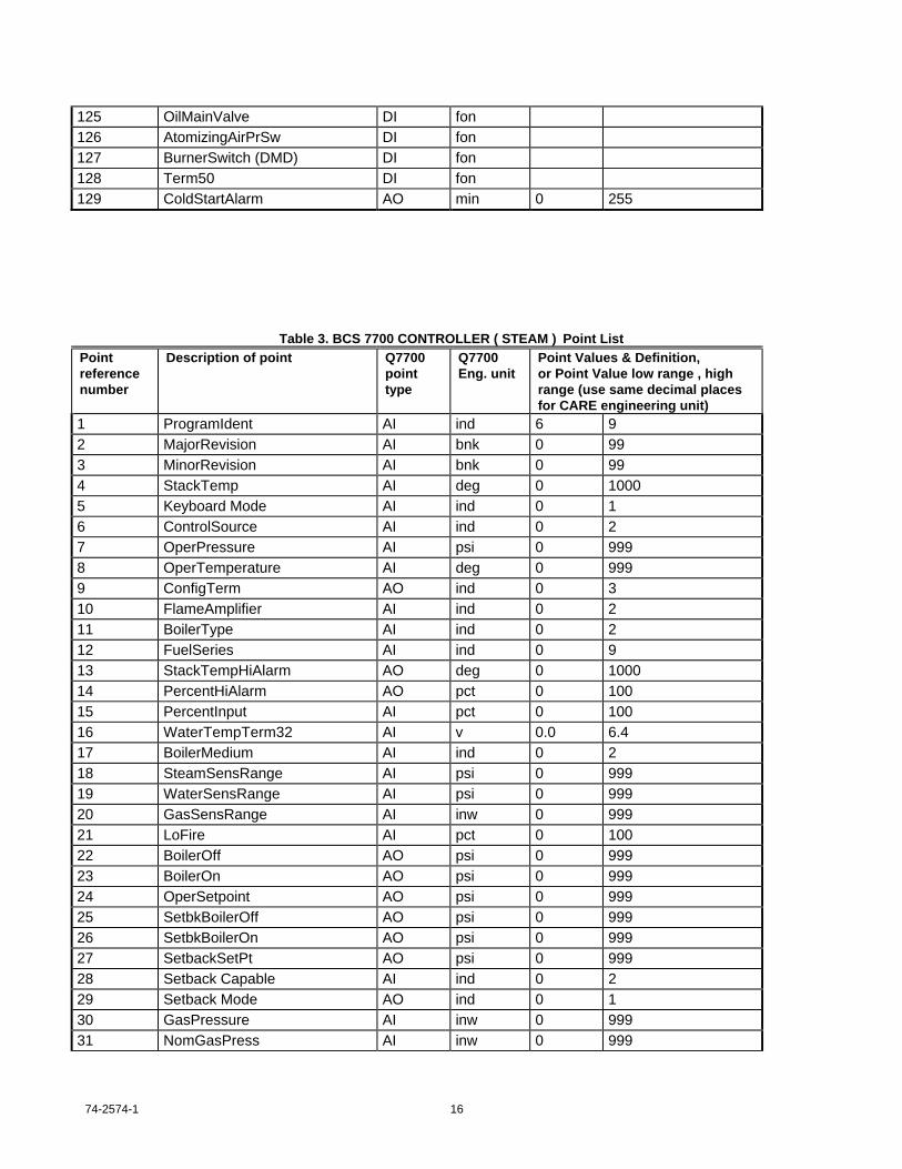
74-2574-1 16
125 OilMainValve DI fon126 AtomizingAirPrSw DI fon127 BurnerSwitch (DMD) DI fon128 Term50 DI fon129 ColdStartAlarm AO min 0 255
Table 3. BCS 7700 CONTROLLER ( STEAM ) Point ListPointreferencenumber
Description of point Q7700pointtype
Q7700Eng. unit
Point Values & Definition,or Point Value low range , highrange (use same decimal placesfor CARE engineering unit)
1 ProgramIdent AI ind 6 92 MajorRevision AI bnk 0 993 MinorRevision AI bnk 0 994 StackTemp AI deg 0 10005 Keyboard Mode AI ind 0 16 ControlSource AI ind 0 27 OperPressure AI psi 0 9998 OperTemperature AI deg 0 9999 ConfigTerm AO ind 0 310 FlameAmplifier AI ind 0 211 BoilerType AI ind 0 212 FuelSeries AI ind 0 913 StackTempHiAlarm AO deg 0 100014 PercentHiAlarm AO pct 0 10015 PercentInput AI pct 0 10016 WaterTempTerm32 AI v 0.0 6.417 BoilerMedium AI ind 0 218 SteamSensRange AI psi 0 99919 WaterSensRange AI psi 0 99920 GasSensRange AI inw 0 99921 LoFire AI pct 0 10022 BoilerOff AO psi 0 99923 BoilerOn AO psi 0 99924 OperSetpoint AO psi 0 99925 SetbkBoilerOff AO psi 0 99926 SetbkBoilerOn AO psi 0 99927 SetbackSetPt AO psi 0 99928 Setback Capable AI ind 0 229 Setback Mode AO ind 0 130 GasPressure AI inw 0 99931 NomGasPress AI inw 0 999

17 74-2574-1
32 LoGasLimit AI inw 0 99933 HiGasLimit AI inw 0 99934 OilPressSensRange AI psi 0 15035 OilPressure AI psi 0 15036 NomOilPress AI psi 30 13537 LoOilPressLimit AI psi 24 12638 HiOilPressLimit AI psi 32 14539 OilTempSensRange AI deg 0 30040 OilTemperature AI deg 0 30041 NomOilTemp AI deg 60 26542 LoOilTempLimit AI deg 51 24443 HiOilTempLimit AI deg 65 29044 Response AO bnk 1 545 MaxFire AO pct 0 10046 PrepurgeExtend AI sec 0 900047 PostpurgeExtend AI sec 0 900048 Total Cycles AI bnk 0 6553549 H1 Fault Cycle AI bnk 0 6553550 H2 Fault Cycle AI bnk 0 6553551 H3 Fault Cycle AI bnk 0 6553552 H4 Fault Cycle AI bnk 0 6553553 H5 Fault Cycle AI bnk 0 6553554 H6 Fault Cycle AI bnk 0 6553555 Total Hours AI hr 0 6553556 H1 Fault Hours AI hr 0 6553557 H2 Fault Hours AI hr 0 6553558 H3 Fault Hours AI hr 0 6553559 H4 Fault Hours AI hr 0 6553560 H5 Fault Hours AI hr 0 6553561 H6 Fault Hours AI hr 0 6553562 H1 Fault Code AI bnk 0 25563 H2 Fault Code AI bnk 0 25564 H3 Fault Code AI bnk 0 25565 H4 Fault Code AI bnk 0 25566 H5 Fault Code AI bnk 0 25567 H6 Fault Code AI bnk 0 25568 H1 Fault Message AI ind 0 8269 H2 Fault Message AI ind 0 8270 H3 Fault Message AI ind 0 8271 H4 Fault Message AI ind 0 8272 H5 Fault Message AI ind 0 8273 H6 Fault Message AI ind 0 8274 BurnerStatus AI ind 0 1475 H1 BurnerStatus AI ind 0 1476 H2 BurnerStatus AI ind 0 1477 H3 BurnerStatus AI ind 0 14

74-2574-1 18
78 H4 BurnerStatus AI ind 0 1479 H5 BurnerStatus AI ind 0 1480 H6 BurnerStatus AI ind 0 1481 BurnerStatusExt AI ind 0 1582 H1 BurnerStatusExt AI ind 0 1583 H2 BurnerStatusExt AI ind 0 1584 H3 BurnerStatusExt AI ind 0 1585 H4 BurnerStatusExt AI ind 0 1586 H5 BurnerStatusExt AI ind 0 1587 H6 BurnerStatusExt AI ind 0 1588 FireRateMode AI ind 0 189 FireRate AI pct 0 10090 H1 FireRate AI pct 0 10091 H2 FireRate AI pct 0 10092 H3 FireRate AI pct 0 10093 H4 FireRate AI pct 0 10094 H5 FireRate AI pct 0 10095 H6 FireRate AI pct 0 10096 SequenceTimer AI sec 0 6553597 H1 SequenceTimer AI sec 0 6553598 H2 SequenceTimer AI sec 0 6553599 H3 SequenceTimer AI sec 0 65535100 H4 SequenceTimer AI sec 0 65535101 H5 SequenceTimer AI sec 0 65535102 H6 SequenceTimer AI sec 0 65535103 FuelSelection AI ind 0 7104 H1 FuelSelection AI ind 0 7105 H2 FuelSelection AI ind 0 7106 H3 FuelSelection AI ind 0 7107 H4 FuelSelection AI ind 0 7108 H5 FuelSelection AI ind 0 7109 H6 FuelSelection AI ind 0 7110 FlameSignal AI v 0.0 5.0111 GasPressureTerm46 AI v 0.0 6.4112 OilPressureTerm43 AI v 0.0 6.4113 OilTempTerm34 AI v 0.0 6.4114 StmPressTerm37 AI v 0.0 6.4115 PercentLoAlarm AO pct 0 100116 DampMotorTerm40 AI v 0.0 8.4117 GasFuelSelect DI fon118 OilFuelSelect DI fon119 Term51 DI fon120 PreIgnInterlock DI fon121 RecycleLimit DI fon122 LockoutInterlock DI fon123 PilotValve DI fon

19 74-2574-1
124 GasMainValve DI fon125 OilMainValve DI fon126 AtomizingAirPrSw DI fon127 BurnerSwitch (DMD) DI fon128 Term50 DI fon129 ColdStartAlarm AO min 0 255
RM 7800 Controller
The following information is provided from RM7800 documentation. The information is included here to help you understandthe RM7800.
RM7800 Controller
The RM7800 controller is a burner control system. The RM7800 is available in a variety of model types to be used in avariety of applications. The points which exist in each model are listed in the matrix table below.
TABLE 4 RM 7800 Controller Model Point Matrix
RM7800
G
RM7840
G
RM7800
L
RM7840
L
RM7895
A
RM7895
C
RM7800
E
RM7840M
RM7823 RM7885 RM7890 RM7895
B
RM7895
D
RM7840
E
RM7800M RM7838
A
RM7838
B
(1
Valid)
(1
Valid)
(1
Valid)
(1
Valid)
(1
Valid)
(1
Valid)
(1 Valid) (1
Valid)
(1
Valid)
BurnerAvailability 1 1 1 1 1 1 1 1 1Remote Command 1 1 1 1 1 1 1 1 1Flame Signal 1 1 1 1 1 1 1 1 1Run/Test Switch 0 0 0 0 1 1 1 1 1PilotValveHold T16 0 0 0 0 0 0 0 0 1Manual-Open SwT17
0 0 0 0 0 0 0 0 1
LowFire Switch T18 0 0 0 0 0 1 1 0 1HighFireSwitch T19 0 0 0 0 0 1 0 1 1Valve 2/Start T21 0 0 0 0 1 1 1 1 1PreIgn. ILK T20 0 0 0 0 0 1 1 0 1Oper. Control T6 1 1 1 1 1 1 1 1 1Ignition T10 0 1 1 1 1 1 1 1 1Main Valve T9 1 1 1 1 1 1 1 1 1Pilot Valve T8 0 1 1 1 1 1 1 1 1

74-2574-1 20
Interlock T7 0 0 0 1 1 1 1 1 1Purge Time 0 0 0 1 1 1 1 1 1Amplifier Type 1 1 1 1 1 1 1 1 1Jumper 1 0 1 1 1 1 1 1 1 1Jumper 2 0 1 1 1 1 1 1 1 1Jumper 3 0 1 1 1 1 1 1 1 1Flame Response 1 1 1 1 1 1 1 1 1Sequence Status 1 1 1 1 1 1 1 1 1Sequence Extension 1 1 1 1 1 1 1 1 1Sequence Timer 1 1 1 1 1 1 1 1 1Total Cycles 1 1 1 1 1 1 1 1 1Total Hours 1 1 1 1 1 1 1 1 1H1 Fault Code 1 1 1 1 1 1 1 1 1H1 Fault Message 1 1 1 1 1 1 1 1 1H1 Sequence Status 1 1 1 1 1 1 1 1 1H1 Sequence Ext. 1 1 1 1 1 1 1 1 1H1 Sequence Timer 1 1 1 1 1 1 1 1 1H1 Fault Cycle 1 1 1 1 1 1 1 1 1H1 Fault Hour 1 1 1 1 1 1 1 1 1H2 Fault Code 1 1 1 1 1 1 1 1 1H2 Fault Message 1 1 1 1 1 1 1 1 1H2 Sequence Status 1 1 1 1 1 1 1 1 1H2 Sequence Ext. 1 1 1 1 1 1 1 1 1H2 Sequence Timer 1 1 1 1 1 1 1 1 1H2 Fault Cycle 1 1 1 1 1 1 1 1 1H2 Fault Hour 1 1 1 1 1 1 1 1 1H3 Fault Code 1 1 1 1 1 1 1 1 1H3 Fault Message 1 1 1 1 1 1 1 1 1H3 Sequence Status 1 1 1 1 1 1 1 1 1H3 Sequence Ext. 1 1 1 1 1 1 1 1 1H3 Sequence Timer 1 1 1 1 1 1 1 1 1H3 Fault Cycle 1 1 1 1 1 1 1 1 1H3 Fault Hour 1 1 1 1 1 1 1 1 1H4 Fault Code 1 1 1 1 1 1 1 1 1H4 Fault Message 1 1 1 1 1 1 1 1 1H4 Sequence Status 1 1 1 1 1 1 1 1 1H4 Sequence Ext. 1 1 1 1 1 1 1 1 1H4 Sequence Timer 1 1 1 1 1 1 1 1 1H4 Fault Cycle 1 1 1 1 1 1 1 1 1H4 Fault Hour 1 1 1 1 1 1 1 1 1H5 Fault Code 1 1 1 1 1 1 1 1 1H5 Fault Message 1 1 1 1 1 1 1 1 1H5 Sequence Status 1 1 1 1 1 1 1 1 1H5 Sequence Ext. 1 1 1 1 1 1 1 1 1H5 Sequence Timer 1 1 1 1 1 1 1 1 1H5 Fault Cycle 1 1 1 1 1 1 1 1 1H5 Fault Hour 1 1 1 1 1 1 1 1 1H6 Fault Code 1 1 1 1 1 1 1 1 1H6 Fault Message 1 1 1 1 1 1 1 1 1H6 Sequence Status 1 1 1 1 1 1 1 1 1

21 74-2574-1
H6 Sequence Ext. 1 1 1 1 1 1 1 1 1H6 Sequence Timer 1 1 1 1 1 1 1 1 1H6 Fault Cycle 1 1 1 1 1 1 1 1 1H6 Fault Hour 1 1 1 1 1 1 1 1 1Line Frequency 1 1 1 1 1 1 1 1 1
Table 5. RM 7800 Point ListPointreferencenumber
Description of point Q7700pointtype
Q7700Eng. unit
Point Values & Definition, orPoint Value low range, high range(use same decimal places forCARE engineering unit)LOW HIGH
1 Burner Availability AI ind 0 32 Remote Command AI ind 0 33 Flame Signal AI v 0.0 5.04 Run/Test Switch AI ind 0 15 PilotValveHold T16 DI fon6 Manual-Open Sw T17 DI fon7 LowFire Switch T18 DI fon8 HighFireSwitch T19 DI fon9 Valve 2/Start T21 DI fon10 PreIgn. ILK T20 DI fon11 Oper. Control T6 DI fon12 Ignition T10 DI fon13 Main Valve T9 DI fon14 Pilot Valve T8 DI fon15 Interlock T7 DI fon16 Purge Time AI sec 2 180017 Amplifier Type AI ind 0 318 Jumper 1 AI ind 0 119 Jumper 2 AI ind 0 120 Jumper 3 AI ind 0 121 Flame Response AI ind 0 122 Sequence Status AI ind 0 3523 Sequence Extension AI ind 0 4124 Sequence Timer AI sec 0 409525 Total Cycles AI cnt 0 9999926 Total Hours AI hr 0 9999927 H1 Fault Code AI ind 0 25528 H1 Fault Message AI ind 0 5829 H1 Sequence Status AI ind 0 3530 H1 Sequence Ext. AI ind 0 4131 H1 Sequence Timer AI sec 0 4095

74-2574-1 22
32 H1 Fault Cycle AI cnt 0 9999933 H1 Fault Hour AI hr 0 9999934 H2 Fault Code AI ind 0 25535 H2 Fault Message AI ind 0 5836 H2 Sequence Status AI ind 0 3537 H2 Sequence Ext. AI ind 0 4138 H2 Sequence Timer AI sec 0 409539 H2 Fault Cycle AI cnt 0 9999940 H2 Fault Hour AI hr 0 9999941 H3 Fault Code AI ind 0 25542 H3 Fault Message AI ind 0 5843 H3 Sequence Status AI ind 0 3544 H3 Sequence Ext. AI ind 0 4145 H3 Sequence Timer AI sec 0 409546 H3 Fault Cycle AI cnt 0 9999947 H3 Fault Hour AI hr 0 9999948 H4 Fault Code AI ind 0 25549 H4 Fault Message AI ind 0 5850 H4 Sequence Status AI ind 0 3551 H4 Sequence Ext. AI ind 0 4152 H4 Sequence Timer AI sec 0 409553 H4 Fault Cycle AI cnt 0 9999954 H4 Fault Hour AI hr 0 9999955 H5 Fault Code AI ind 0 25556 H5 Fault Message AI ind 0 5857 H5 Sequence Status AI ind 0 3558 H5 Sequence Ext. AI ind 0 4159 H5 Sequence Timer AI sec 0 409560 H5 Fault Cycle AI cnt 0 9999961 H5 Fault Hour AI hr 0 9999962 H6 Fault Code AI ind 0 25563 H6 Fault Message AI ind 0 5864 H6 Sequence Status AI ind 0 3565 H6 Sequence Ext. AI ind 0 4166 H6 Sequence Timer AI sec 0 409567 H6 Fault Cycle AI cnt 0 9999968 H6 Fault Hour AI hr 0 9999969 Line Frequency AI ind 0 1

23 74-2574-1
S7830 Annunciator
The following information is provided from S7830 documentation. The information is included here to help you understandthe S7830.
S7830 Annunciator
The S7830 Annunciator provides an operator interface into the RM7800 off of the same bus ( slot ) from the Q7700controller. A description of the points which can be obtained from the S7830 by the OpenLink is listed in the table below:
Table 6. S7830 Expanded AnnunciatorPointreferencenumber
Description of point Q7700pointtype
Q7700Eng. unit
Point Values & Definition, orPoint Value high range, low range(use same decimal places for CAREengineering unit
1 Current Status AI ind 0 202 Fault First Out AI ind 0 203 Fault ValveClosure AI ind 0 24 Valve Closure T4 DI fon5 Burner Switch T5 DI fon6 Oper. Control T6 DI fon7 Aux. Limit #1 T7 DI fon8 Aux. Limit #2 T8 DI fon9 LWCO T9 DI fon10 High Limit T10 DI fon11 Aux. Limit #3 T11 DI fon12 Oil Select T12 DI fon13 Hi OilPressure T13 DI fon14 LowOilPressure T14 DI fon15 High Oil Temp. T15 DI fon16 Low Oil Temp. T16 DI fon17 Atomizing Sw. T19 DI fon18 Gas Select T17 DI fon19 Hi GasPressure T18 DI fon20 LowGasPressure T19 DI fon21 Airflow Switch T20 DI fon22 Aux. ILK #4 T21 DI fon23 Aux. ILK #5 T22 DI fon

74-2574-1 24
Armstrong TRAPSCAN Trap Monitoring System
The following information is provided from TrapScan documentation. The information is included here to help youunderstand the TrapScan.
TrapScan Series 2000
The TrapScan Series 2000 monitors conditions inside steam traps. This information can be used to improve/demonstrateenergy saving trap performance. The product features a temperature/condensate profile probe, more accurate than othermethods, that measures conditions inside an inverted bucket trap.
The TrapScan requires that the point ScanRequest be commanded to 1 in order to update the trap conditions. TheTrapScan will reset this point once the scan has begun. The points in the TrapScan system have been separated into twotables - one for the system points ( which occur once per TrapScan subsystem ) and one table for the points in a TrapScanZone. A TrapScan may have 1 to 25 zones . A description of the points that can be obtained from the TrapScan by theOpenLink is listed in the tables below:
Table 7. TRAPSCAN Point ListPointreferencenumber
Description of point Q7700pointtype
Q7700Eng. unit
Point Values & Definition, orPoint Value low range, high range(use same decimal places forCARE engineering unit)LOW HIGH
1 SoftwareMajorRev AI ind 0 2552 SoftwareMinorRev AI ind 0 2553 SoftwareVersion AI ind 0 2554 ResetSequenceNum AI ind 0 2555 NumberOfTraps AI ind 0 256 TimeSinceLastScan AI ind 0 655357 ScanSequenceNumber AI ind 0 2558 NormalScanInterval AO ind 0 2559 PrimeScanInterval AO ind 0 25510 ScanRequest AO ind 0 111 ScanProgress AI ind 0 25512 PrimeLossSamples AO ind 0 255
Table 8. TRAPSCAN ZONE Point ListPointreferencenumber
Description of point Q7700pointtype
Q7700Eng. unit
Point Values & Definition, orPoint Value low range, high range(use same decimal places forCARE engineering unit)LOW HIGH
1 Status Zone Trap A AI ind 0 2552 Status Zone Trap B AI ind 0 2553 Status Zone Trap C AI ind 0 2554 Status Zone Trap D AI ind 0 2555 Status Zone Trap E AI ind 0 255
25 74-2574-1
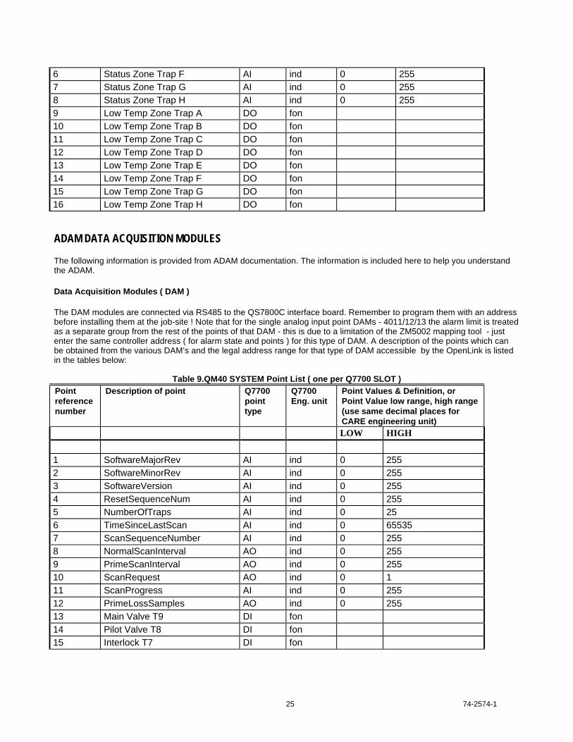
6 Status Zone Trap F AI ind 0 2557 Status Zone Trap G AI ind 0 2558 Status Zone Trap H AI ind 0 2559 Low Temp Zone Trap A DO fon10 Low Temp Zone Trap B DO fon11 Low Temp Zone Trap C DO fon12 Low Temp Zone Trap D DO fon13 Low Temp Zone Trap E DO fon14 Low Temp Zone Trap F DO fon15 Low Temp Zone Trap G DO fon16 Low Temp Zone Trap H DO fon
ADAM DATA ACQUISITION MODULES
The following information is provided from ADAM documentation. The information is included here to help you understandthe ADAM.
Data Acquisition Modules ( DAM )
The DAM modules are connected via RS485 to the QS7800C interface board. Remember to program them with an addressbefore installing them at the job-site ! Note that for the single analog input point DAMs - 4011/12/13 the alarm limit is treatedas a separate group from the rest of the points of that DAM - this is due to a limitation of the ZM5002 mapping tool - justenter the same controller address ( for alarm state and points ) for this type of DAM. A description of the points which canbe obtained from the various DAM’s and the legal address range for that type of DAM accessible by the OpenLink is listedin the tables below:
Table 9.QM40 SYSTEM Point List ( one per Q7700 SLOT )Pointreferencenumber
Description of point Q7700pointtype
Q7700Eng. unit
Point Values & Definition, orPoint Value low range, high range(use same decimal places forCARE engineering unit)LOW HIGH
1 SoftwareMajorRev AI ind 0 2552 SoftwareMinorRev AI ind 0 2553 SoftwareVersion AI ind 0 2554 ResetSequenceNum AI ind 0 2555 NumberOfTraps AI ind 0 256 TimeSinceLastScan AI ind 0 655357 ScanSequenceNumber AI ind 0 2558 NormalScanInterval AO ind 0 2559 PrimeScanInterval AO ind 0 25510 ScanRequest AO ind 0 111 ScanProgress AI ind 0 25512 PrimeLossSamples AO ind 0 25513 Main Valve T9 DI fon14 Pilot Valve T8 DI fon15 Interlock T7 DI fon

74-2574-1 26
Table 10. QM4011/4012A/4013 ANALOG INPUT DAM Point List ( 1 - 128 )Pointreferencenumber
Description of point Q7700pointtype
Q7700Eng. unit
Point Values & Definition, orPoint Value low range, high range(use same decimal places forCARE engineering unit)LOW HIGH
1 Analog In-Alarm Status AI ind 0 255
Table 11. QM4011/4012A/4013 ANALOG INPUT DAM Point List ( 1 - 128 )Pointreferencenumber
Description of point Q7700pointtype
Q7700Eng. unit
Point Values & Definition, orPoint Value low range, high range(use same decimal places forCARE engineering unit)LOW HIGH
1 Analog Input Conversion AO ind 0 2552 Analog Input AI float -
99999.9999999.99
3 Analog Input Alarm Enable AO ind 0 14 Analog Input Low Alarm AO float above above5 Analog Input High Alarm AO float above above
Table 12. QM4017/18 8 CHANNEL ANALOG INPUT DAM Point List( 0 - 7 )Pointreferencenumber
Description of point Q7700pointtype
Q7700Eng. unit
Point Values & Definition, orPoint Value low range, high range(use same decimal places forCARE engineering unit)LOW HIGH
1 Analog Input Conversion AO ind 0 2552 Analog Input 0 AI float -99999.9 99999.93 Analog Input 1 AI float -99999.9 99999.94 Analog Input 2 AI float -99999.9 99999.95 Analog Input 3 AI float -99999.9 99999.96 Analog Input 4 AI float -99999.9 99999.97 Analog Input 5 AI float -99999.9 99999.98 Analog Input 6 AI float -99999.9 99999.99 Analog Input 7 AI float -99999.9 99999.9

27 74-2574-1
Table 13. QM4017/18 8 CHANNEL ANALOG INPUT DAM Point List( 0 - 3 )with individual conversion factors
Pointreferencenumber
Description of point Q7700pointtype
Q7700Eng. unit
Point Values & Definition, orPoint Value low range, high range(use same decimal places forCARE engineering unit)LOW HIGH
1 Analog Input Conversion 0 AO ind 0 2552 Analog Input 0 AI float -99999.9 99999.93 Analog Input Conversion 1 AO ind 0 2554 Analog Input 1 AI float -99999.9 99999.95 Analog Input Conversion 2 AO ind 0 2556 Analog Input 2 AI float -99999.9 99999.97 Analog Input Conversion 3 AO ind 0 2558 Analog Input 3 AI float -99999.9 99999.99 Analog Input Conversion 4 AO ind 0 25510 Analog Input 4 AI float -99999.9 99999.911 Analog Input Conversion 5 AO ind 0 25512 Analog Input 5 AI float -99999.9 99999.913 Analog Input Conversion 6 AO ind 0 25514 Analog Input 6 AI float -99999.9 99999.915 Analog Input Conversion 7 AO ind 0 25516 Analog Input 7 AI float -99999.9 99999.9
Table 14. QM4052 Digital Input DAM Point List ( 0 - 5 )Pointreferencenumber
Description of point Q7700pointtype
Q7700Eng. unit
Point Values & Definition, orPoint Value low range, high range(use same decimal places forCARE engineering unit)LOW HIGH
1 Digital Input 0 DI fon2 Digital Input 1 DI fon3 Digital Input 2 DI fon4 Digital Input 3 DI fon5 Digital Input 4 DI fon6 Digital Input 5 DI fon7 Digital Input 6 DI fon8 Digital Input 7 DI fon

74-2574-1 28
Table 15. QM4060A Digital Output DAM Point List ( 0 - 3)Pointreferencenumber
Description of point Q7700pointtype
Q7700Eng. unit
Point Values & Definition, orPoint Value low range, high range(use same decimal places forCARE engineering unit)LOW HIGH
1 Digital Output 1 DO fon2 Digital Output 2 DO fon3 Digital Output 3 DO fon4 Digital Output 4 DO fon
PulsaFeeder PULSATROL Series 300
The following information is provided from Pulsatrol documentation. The information is included here to help you understandthe Pulsatrol.
Pulsatrol Series 300
The Pulsatrol is a water monitoring system. Because of the large number of points that are accessible - we have split theminto two groups ( each of which is defined in a table ) A description of the points which can be obtained from the Series 300by the OpenLink is listed in the table below:
Table 16. PULSATROL Group 1 Point List
Pointreferencenumber
Description Pulsatrolpoint type
CAREpointtype
Eng.Units
Point information
118 Aux1 AI PA119 Aux1HighAlarm AO PA120 Aux1LowAlarm AO PA121 Aux2 AI PA122 Aux2HighAlarm AO PA123 Aux2LowAlarm AO PA124 Aux3 AI PA125 Aux3HighAlarm AO PA126 Aux3LowAlarm AO PA127 Aux4 AI PA128 Aux4HighAlarm AO PA129 Aux4LowAlarm AO PA189 BioACondMin AO PA186 BioAFeedLimit AO PA Min190 BioAFeedTimer AI PA Min188 BioALockoutLimit AO PA Min192 BioALockoutTimer AI PA Min193 BioAOutput AI PA See Table PT-6

29 74-2574-1
187 BioAPreBleedLimit AO PA Min191 BioAPreBleedTimer AI PA Min178 BioASched1Day AO PA See Table PT-10170 BioASched1Month AO PA See Table PT-8182 BioASched1Start AO PA Min174 BioASched1Week AO PA See Table PT-9179 BioASched2Day AO PA See Table PT-10171 BioASched2Month AO PA See Table PT-8183 BioASched2Start AO PA Min175 BioASched2Week AO PA See Table PT-9180 BioASched3Day AO PA See Table PT-10172 BioASched3Month AO PA See Table PT-8184 BioASched3Start AO PA Min176 BioASched3Week AO PA See Table PT-9181 BioASched4Day AO PA See Table PT-10173 BioASched4Month AO PA See Table PT-8185 BioASched4Start AO PA Min177 BioASched4Week AO PA See Table PT-9213 BioBCondMin AO PA210 BioBFeedLimit AO PA Min214 BioBFeedTimer AI PA Min212 BioBLockoutLimit AO PA Min216 BioBLockoutTimer AI PA Min217 BioBOutput AI PA See Table PT-6211 BioBPreBleedLimit AO PA Min215 BioBPreBleedTimer AI PA Min202 BioBSched1Day AO PA See Table PT-10194 BioBSched1Month AO PA See Table PT-8206 BioBSched1Start AO PA Min198 BioBSched1Week AO PA See Table PT-9203 BioBSched2Day AO PA See Table PT-10195 BioBSched2Month AO PA See Table PT-8207 BioBSched2Start AO PA Min199 BioBSched2Week AO PA See Table PT-9204 BioBSched3Day AO PA See Table PT-10196 BioBSched3Month AO PA See Table PT-8208 BioBSched3Start AO PA Min200 BioBSched3Week AO PA See Table PT-9205 BioBSched4Day AO PA See Table PT-10197 BioBSched4Month AO PA See Table PT-8209 BioBSched4Start AO PA Min201 BioBSched4Week AO PA See Table PT-9237 BioCCondMin AO PA234 BioCFeedLimit AO PA Min238 BioCFeedTimer AI PA Min236 BioCLockoutLimit AO PA Min240 BioCLockoutTimer AI PA Min241 BioCOutput AI PA See Table PT-6235 BioCPreBleedLimit AO PA Min239 BioCPreBleedTimer AI PA Min226 BioCSched1Day AO PA See Table PT-10218 BioCSched1Month AO PA See Table PT-8230 BioCSched1Start AO PA Min

74-2574-1 30
222 BioCSched1Week AO PA See Table PT-9227 BioCSched2Day AO PA See Table PT-10219 BioCSched2Month AO PA See Table PT-8231 BioCSched2Start AO PA Min223 BioCSched2Week AO PA See Table PT-9228 BioCSched3Day AO PA See Table PT-10220 BioCSched3Month AO PA See Table PT-8232 BioCSched3Start AO PA Min224 BioCSched3Week AO PA See Table PT-9229 BioCSched4Day AO PA See Table PT-10221 BioCSched4Month AO PA See Table PT-8233 BioCSched4Start AO PA Min225 BioCSched4Week AO PA See Table PT-9250 BioDSched1Day AO PA See Table PT-10242 BioDSched1Month AO PA See Table PT-8254 BioDSched1Start AO PA Min246 BioDSched1Week AO PA See Table PT-9251 BioDSched2Day AO PA See Table PT-10243 BioDSched2Month AO PA See Table PT-8255 BioDSched2Start AO PA Min247 BioDSched2Week AO PA See Table PT-9252 BioDSched3Day AO PA See Table PT-10244 BioDSched3Month AO PA See Table PT-8248 BioDSched3Week AO PA See Table PT-9253 BioDSched4Day AO PA See Table PT-10245 BioDSched4Month AO PA See Table PT-8249 BioDSched4Week AO PA See Table PT-9035 Cond1 AI PA040 Cond1AlarmDiff AO PA043 Cond1BoilerDur AO PA Sec042 Cond1BoilerInt AO PA Min044 Cond1BoilSample AO PA See Table PT-11038 Cond1HighAlarm AO PA039 Cond1LowAlarm AO PA079 Cond1Max AI PA045 Cond1Output AI PA See Table PT-6037 Cond1Rise/Fall AO PA See Table PT-16041 Cond1SetpDiff AO PA036 Cond1SetPoint AO PA046 Cond2 AI PA051 Cond2AlarmDiff AO PA054 Cond2BoilerDur AO PA Sec053 Cond2BoilerInt AO PA Min055 Cond2BoilSample AO PA See Table PT-11049 Cond2HighAlarm AO PA050 Cond2LowAlarm AO PA080 Cond2Max AI PA056 Cond2Output AI PA See Table PT-6048 Cond2Rise/Fall AO PA See Table PT-16052 Cond2SetpDiff AO PA047 Cond2SetPoint AO PA057 Cond3 AI PA062 Cond3AlarmDiff AO PA

31 74-2574-1
065 Cond3BoilerDur AO PA Sec064 Cond3BoilerInt AO PA Min066 Cond3BoilSample AO PA See Table PT-11060 Cond3HighAlarm AO PA061 Cond3LowAlarm AO PA081 Cond3Max AI PA067 Cond3Output AI PA See Table PT-6059 Cond3Rise/Fall AO PA See Table PT-16063 Cond3SetpDiff AO PA058 Cond3SetPoint AO PA068 Cond4 AI PA073 Cond4AlarmDiff AO PA076 Cond4BoilerDur AO PA Sec075 Cond4BoilerInt AO PA Min077 Cond4BoilSample AO PA See Table PT-11071 Cond4HighAlarm AO PA072 Cond4LowAlarm AO PA082 Cond4Max AI PA078 Cond4Output AI PA See Table PT-6070 Cond4Rise/Fall AO PA See Table PT-16074 Cond4SetpDiff AO PA069 Cond4SetPoint AO PA019 HighAlarmAux1 AI PA See Table PT-12020 HighAlarmAux2 AI PA See Table PT-12021 HighAlarmAux3 AI PA See Table PT-12022 HighAlarmAux4 AI PA See Table PT-12018 HighAlarmMUCond AI PA See Table PT-12012 HighAlarmSysCond1 AI PA See Table PT-12013 HighAlarmSysCond2 AI PA See Table PT-12014 HighAlarmSysCond3 AI PA See Table PT-12015 HighAlarmSysCond4 AI PA See Table PT-12017 HighAlarmSysORP AI PA See Table PT-12016 HighAlarmSysPH AI PA See Table PT-12130 Inh1FeedTimerType AO PA See Table PT-13134 Inh1LimitTime AO PA Min139 Inh1Output AI PA See Table PT-6131 Inh1Percent AO PA PCT132 Inh1PercentMinutes AO PA Min133 Inh1PostBleed% AO PA PCT137 Inh1PulseCounter AI PA136 Inh1PulseRunTime AO PA Sec135 Inh1PulseSet AO PA138 Inh1PulseTotalizer AO PA140 Inh2FeedTimerType AO PA See Table PT-13144 Inh2LimitTime AO PA Min149 Inh2Output AI PA See Table PT-6141 Inh2Percent AO PA PCT142 Inh2PercentMinutes AO PA Min143 Inh2PostBleed% AO PA PCT147 Inh2PulseCounter AI PA146 Inh2PulseRunTime AO PA Sec145 Inh2PulseSet AO PA148 Inh2PulseTotalizer AO PA

74-2574-1 32
150 Inh3FeedTimerType AO PA See Table PT-13154 Inh3LimitTime AO PA Min159 Inh3Output AI PA See Table PT-6151 Inh3Percent AO PA PCT152 Inh3PercentMinutes AO PA Min153 Inh3PostBleed% AO PA PCT157 Inh3PulseCounter AI PA156 Inh3PulseRunTime AO PA Sec155 Inh3PulseSet AO PA158 Inh3PulseTotalizer AO PA160 Inh4FeedTimerType AO PA See Table PT-13164 Inh4LimitTime AO PA Min169 Inh4Output AI PA See Table PT-6161 Inh4Percent AO PA PCT162 Inh4PercentMinutes AO PA Min163 Inh4PostBleed% AO PA PCT167 Inh4PulseCounter AI PA166 Inh4PulseRunTime AO PA Sec165 Inh4PulseSet AO PA168 Inh4PulseTotalizer AO PA008 InhTimeAlarm1 AI PA See Table PT-12009 InhTimeAlarm2 AI PA See Table PT-12010 InhTimeAlarm3 AI PA See Table PT-12011 InhTimeAlarm4 AI PA See Table PT-12006 LimitTimeSysORP AI PA See Table PT-12007 LimitTimeSysPH AI PA See Table PT-12030 LowAlarmAux1 AI PA See Table PT-12031 LowAlarmAux2 AI PA See Table PT-12032 LowAlarmAux3 AI PA See Table PT-12033 LowAlarmAux4 AI PA See Table PT-12029 LowAlarmMUCond AI PA See Table PT-12023 LowAlarmSysCond1 AI PA See Table PT-12024 LowAlarmSysCond2 AI PA See Table PT-12025 LowAlarmSysCond3 AI PA See Table PT-12026 LowAlarmSysCond4 AI PA See Table PT-12028 LowAlarmSysORP AI PA See Table PT-12027 LowAlarmSysPH AI PA See Table PT-12101 MakeupConductivity AI PA102 MakeupCycles AI PA114 MakeupHighAlarm AO PA115 MakeupLowAlarm AO PA117 MakeupMax AI PA108 MakeupRange1Setp AO PA109 MakeupRange2Setp AO PA110 MakeupRange3Setp AO PA111 MakeupRange4Setp AO PA112 MakeupRange5Setp AO PA103 MakeupScaleRange1 AO PA104 MakeupScaleRange2 AO PA105 MakeupScaleRange3 AO PA106 MakeupScaleRange4 AO PA107 MakeupScaleRange5 AO PA116 MakeupSetpDiff AO PA

33 74-2574-1
113 MakeupSetPoint AO PA005 NoFlow AI PA See Table PT-12092 ORP AI PA097 ORPAlarmDiff AO PA095 ORPHighAlarm AO PA099 ORPLimitTimer AO PA Min096 ORPLowAlarm AO PA100 ORPOutput AI PA See Table PT-6094 ORPRise/Fall AO PA See Table PT-16098 ORPSetpDiff AO PA093 ORPSetPoint AO PA083 PH AI PA PH088 PHAlarmDiff AO PA PH086 PHHighAlarm AO PA PH090 PHLimitTimer AO PA Min087 PHLowAlarm AO PA PH091 PHOutput AI PA See Table PT-6085 PHRise/Fall AO PA See Table PT-16089 PHSetpDiff AO PA PH084 PHSetPoint AO PA PH004 ResetSequenceNum AI PA001 SoftwareMajorRev AI PA See Table PT-1002 SoftwareMinorRev AI PA003 SoftwareVersion AI PA034 UnrecognizedAlarm AI PA See Table PT-12
Table 18 PULSATROL Group 2 Point List
Pointreferencenumber
Description Pulsatrolpointtype
CAREpoint type
Eng.Units
Point information
084 AlarmLEDStatus AI PA See Table PT-1018 AlarmRelayStatus AI PA See Table PT-1076 AlarmSelect AO PA See Table PT-2074 AnalogDampener AO PA Sec028 AnalogInput1Config AI PA See Table PT-3062 AnalogInput1Use AI PA See Table PT-4029 AnalogInput2Config AI PA See Table PT-3063 AnalogInput2Use AI PA See Table PT-4030 AnalogInput3Config AI PA See Table PT-3064 AnalogInput3Use AI PA See Table PT-4031 AnalogInput4Config AI PA See Table PT-3065 AnalogInput4Use AI PA See Table PT-4032 AnalogInput5Config AI PA See Table PT-3066 AnalogInput5Use AI PA See Table PT-4033 AnalogInput6Config AI PA See Table PT-3067 AnalogInput6Use AI PA See Table PT-4058 Aux1AnalogInput AI PA See Table PT-5059 Aux2AnalogInput AI PA See Table PT-5060 Aux3AnalogInput AI PA See Table PT-5061 Aux4AnalogInput AI PA See Table PT-5

74-2574-1 34
046 BioARelay AI PA See Table PT-7011 BioBlowdownOutpu
tAI PA See Table PT-6
050 BioBlowdownRelay AI PA See Table PT-7047 BioBRelay AI PA See Table PT-7048 BioCRelay AI PA See Table PT-7006 BioDCondMin AO PA003 BioDFeedLimit AO PA Min007 BioDFeedTimer AI PA Min005 BioDLockoutLimit AO PA Min009 BioDLockoutTimer AI PA Min010 BioDOutput AI PA See Table PT-6004 BioDPreBleedLimit AO PA Min008 BioDPreBleedTimer AI PA Min049 BioDRelay AI PA See Table PT-7001 BioDSched3Start AO PA Min002 BioDSched4Start AO PA Min051 Cond1AnalogInput AI PA See Table PT-5036 Cond1Relay AI PA See Table PT-7052 Cond2AnalogInput AI PA See Table PT-5037 Cond2Relay AI PA See Table PT-7053 Cond3AnalogInput AI PA See Table PT-5038 Cond3Relay AI PA See Table PT-7054 Cond4AnalogInput AI PA See Table PT-5039 Cond4Relay AI PA See Table PT-7019 ConfigSequence AI PA078 Date AO PA080 DayOfWeek AO PA See Table PT-10083 DeviceID AO PA082 DeviceName AO PA077 HistoryFrequency AO PA Min042 Inh1Relay AI PA See Table PT-7043 Inh2Relay AI PA See Table PT-7044 Inh3Relay AI PA See Table PT-7045 Inh4Relay AI PA See Table PT-7057 MakeupAnalogInpu
tAI PA See Table PT-5
035 ModelNumber AI PA034 ModelNumberBase AI PA See Table PT-14022 NumberOfAnalogIn
sAI PA
027 NumberOfAuxInputs
AI PA
020 NumberOfBiocides AI PA023 NumberOfCond AI PA021 NumberOfInhibitors AI PA026 NumberOfMakeup AI PA025 NumberOfORP AI PA024 NumberOfPH AI PA056 ORPAnalogInput AI PA See Table PT-5041 ORPRelay AI PA See Table PT-7055 PHAnalogInput AI PA See Table PT-5040 PHRelay AI PA See Table PT-7

35 74-2574-1
075 PulsatrolVersion AI PA012 Relay1Status AI PA See Table PT-6068 Relay1Use AI PA See Table PT-4013 Relay2Status AI PA See Table PT-6069 Relay2Use AI PA See Table PT-4014 Relay3Status AI PA See Table PT-6070 Relay3Use AI PA See Table PT-4015 Relay4Status AI PA See Table PT-6071 Relay4Use AI PA See Table PT-4016 Relay5Status AI PA See Table PT-6072 Relay5Use AI PA See Table PT-4017 Relay6Status AI PA See Table PT-6073 Relay6Use AI PA See Table PT-4081 Time AO PA079 Week AO PA1 See Table PT-15
Table PT-10 = Off1 = On
Table PT-23 = Tracking4 = Independent
Table PT-30 = System PH1 = Conductivity 0-5002 = Conductivity 0-20003 = Conductivity 0-50004 = Conductivity 0-100005 = Conductivity 0-200006 = System ORP7 = Aux Input8 = Unused
Table PT-40 = System Conductivity 11 = System Conductivity 22 = System Conductivity 33 = System Conductivity 44 = System PH5 = System ORP6 = Makeup Conductivity7 = Auxiliary Input 18 = Auxiliary Input 29 = Auxiliary Input 3

74-2574-1 36
10 = Auxiliary Input 411 = Inhibitor 112 = Inhibitor 213 = Inhibitor 314 = Inhibitor 415 = Biocide A16 = Biocide B17 = Biocide C18 = Biocide D19 = BiocideBlowdownEnable20 = Unused
Table PT-50 = Analog Input 11 = Analog Input 22 = Analog Input 33 = Analog Input 44 = Analog Input 55 = Analog Input 616 = Unused
Table PT-61 = Forced Off2 = Forced On3 = Off4 = On9 = Unused
Table PT-70 = Relay11 = Relay22 = Relay33 = Relay44 = Relay55 = Relay66 = Unused
Table PT-80 = Every Month1 = Odd Months2 = Even Months
Table PT-90 = No Week1 = 1st Week2 = 2nd Week3 = 3rd Week4 = 4th Week
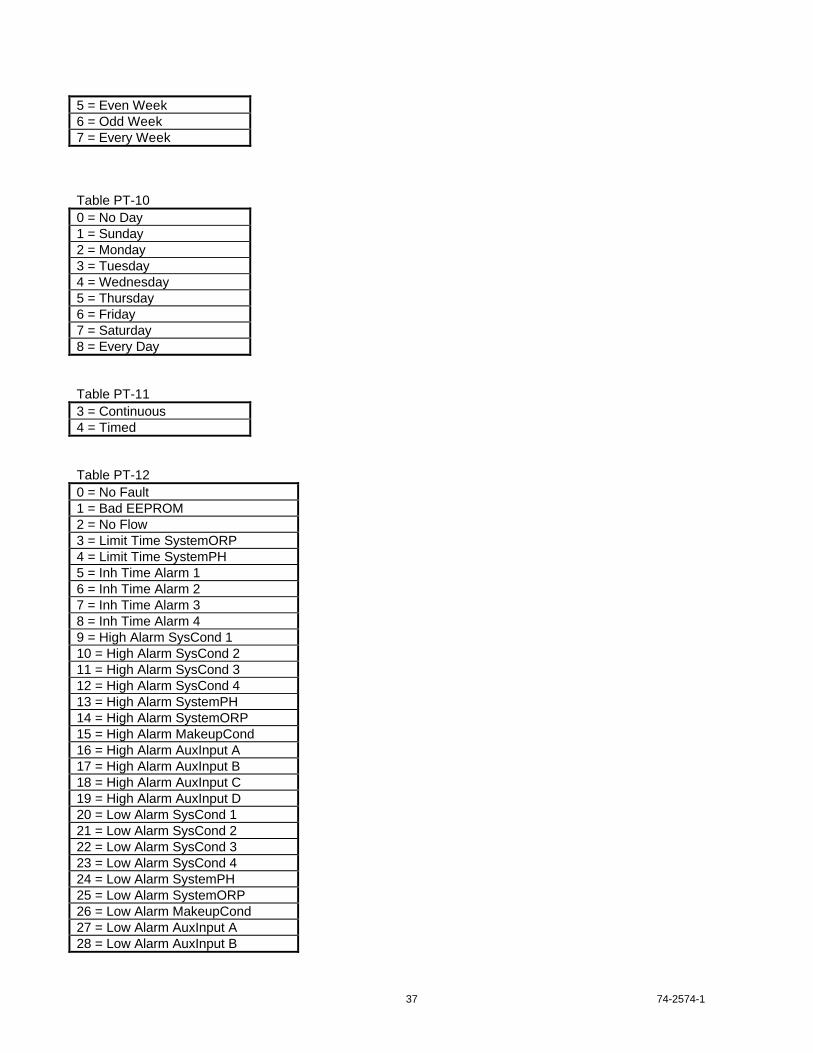
37 74-2574-1
5 = Even Week6 = Odd Week7 = Every Week
Table PT-100 = No Day1 = Sunday2 = Monday3 = Tuesday4 = Wednesday5 = Thursday6 = Friday7 = Saturday8 = Every Day
Table PT-113 = Continuous4 = Timed
Table PT-120 = No Fault1 = Bad EEPROM2 = No Flow3 = Limit Time SystemORP4 = Limit Time SystemPH5 = Inh Time Alarm 16 = Inh Time Alarm 27 = Inh Time Alarm 38 = Inh Time Alarm 49 = High Alarm SysCond 110 = High Alarm SysCond 211 = High Alarm SysCond 312 = High Alarm SysCond 413 = High Alarm SystemPH14 = High Alarm SystemORP15 = High Alarm MakeupCond16 = High Alarm AuxInput A17 = High Alarm AuxInput B18 = High Alarm AuxInput C19 = High Alarm AuxInput D20 = Low Alarm SysCond 121 = Low Alarm SysCond 222 = Low Alarm SysCond 323 = Low Alarm SysCond 424 = Low Alarm SystemPH25 = Low Alarm SystemORP26 = Low Alarm MakeupCond27 = Low Alarm AuxInput A28 = Low Alarm AuxInput B

74-2574-1 38
29 = Low Alarm AuxInput C30 = Low Alarm AuxInput D31 = UnrecognizedPulsatrol32 = No Pulsatrol Response33 = Unsupported Pulsatrol34 = Too Many AnalogInputs35 = Too Many Cond Inputs36 = Too Many PH Inputs37 = Too Many ORP Inputs38 = Too Many Aux Inputs39 = Too Many Inhibitors40 = Too Many Biocides41 = Too Many BioBlowdowns
Table PT-132 = Limit Timer3 = Percent Timer4 = Pulse Timer5 = Post Bleed Timer
Table PT-140 = Unknown1 = MCT2 = MBC3 = MPT4 = GCT
Table PT-151 = 1st Week2 = 2nd Week3 = 3rd Week4 = 4th Week
Table PT-162 = ActionOnRisingInput3 = ActionOnFallingInput
Cleaver Brooks Hawkeye
The following information is provided from Cleaver Brooks Hawkeye documentation. The information is included here tohelp you understand the Cleaver Brooks Hawkeye.
Cleaver Brooks Hawkeye
A description of the points which can be obtained from the Cleaver Brooks Hawkeye by the OpenLink is listed in the tablebelow:

39 74-2574-1
Table 18. Cleaver Brooks Hawkeye
Pointreferencenumber
Description Hawkeyepoint type
CAREpointtype
Eng.Units
Point information
001 AAPS DI PD 0 = 01 = 1
002 ALFC DI PD 0 = 01 = 1
003 BoilerMedium AI PA 0 = Unprogrammed1 = ST2 = HW
004 BoilerOff AO PA005 BoilerOn AO PA006 BoilerSize AI PA HP 0 = Unprogrammed
1 = A12 = A23 = A34 = A45 = A56 = A67 = A78 = A89 = BR110 = BR211 = BR312 = CN113 = CN214 = CN315 = CN416 = CN517 = CN618 = CN7
007 BoilerType AI PA 0 = Unprogrammed1 = CB2 = WT
008 BurnerStatus AI PA 0 = (NotApplicable)1 = STANDBY2 = STANDBYTestSw.3 = PREPURGE4 = PILOTIGNITION5 = PILOTIGNITION6 = FUELCHNG7 = MAINIGN8 = RUN9 = RUN10 = RUNLF-Cutoff11 = RUNFuelChng12 = RUNTestSw.13 = POSTPURGE14 = SAFETYSHUTDOWN
009 H1_BurnerStatus AI PA Same as BurnerStatus010 H2_BurnerStatus AI PA Same as BurnerStatus011 H3_BurnerStatus AI PA Same as BurnerStatus

74-2574-1 40
012 H4_BurnerStatus AI PA Same as BurnerStatus013 H5_BurnerStatus AI PA Same as BurnerStatus014 H6_BurnerStatus AI PA Same as BurnerStatus015 BurnerStatusExt AI PA 0 = (NotApplicable)
1 = HOLD:FuelSelection2 = HOLD:RecycleLimits3 = HOLD:LowFireCutoff4 = HOLD:FlameDetected5 = HOLD:TestSwitch6 = HOLD:OilPressure7 = HOLD:OilTemperature8 = HOLD:DamperMotor9 = HOLD:LockoutInterlock10 = HOLD:OpenOilDrawer11 = DrivetoPurgeRate12 = PurgeTime13 = ExtensionTime14 = DrivetoLowFire15 = LowFireCommanded
016 H1_BurnerStatusExt AI PA Same as BurnerStatusExt017 H2_BurnerStatusExt AI PA Same as BurnerStatusExt018 H3_BurnerStatusExt AI PA Same as BurnerStatusExt019 H4_BurnerStatusExt AI PA Same as BurnerStatusExt020 H5_BurnerStatusExt AI PA Same as BurnerStatusExt021 H6_BurnerStatusExt AI PA Same as BurnerStatusExt022 ControlSource AI PA 0 = AUTO
1 = MAN2 = REM
023 DampMotor AI PA V024 DesignPressure AI PA PSI025 DMD DI PD 0 = 0
1 = 1026 H1_Fault_Code AI PA027 H2_Fault_Code AI PA028 H3_Fault_Code AI PA029 H4_Fault_Code AI PA030 H5_Fault_Code AI PA031 H6_Fault_Code AI PA032 H1_Fault_Cycle AI PA033 H2_Fault_Cycle AI PA034 H3_Fault_Cycle AI PA035 H4_Fault_Cycle AI PA036 H5_Fault_Cycle AI PA037 H6_Fault_Cycle AI PA038 H1_Fault_Hours AI PA HR039 H2_Fault_Hours AI PA HR040 H3_Fault_Hours AI PA HR041 H4_Fault_Hours AI PA HR042 H5_Fault_Hours AI PA HR043 H6_Fault_Hours AI PA HR044 H1_Fault_Message AI PA 0 = Nofault
1 = CallCBService2 = CallCBService3 = CallCBService

41 74-2574-1
4 = CallCBService5 = CallCBService6 = CallCBService7 = CallCBService8 = CallCBService9 = CallCBService10 = FlameAmp/Sensor11 = FlameDetected12 = FlameOutTimer13 = MainFlameFailure14 = PilotFlameFailure15 = GasPressureSensor16 = GasPressureSensor17 = LowGasPress/Sensor18 = HighGasPress/Sensor19 = GasPressureSensor20 = FuelSelection21 = FuelSelection22 = CallCBService23 = CallCBService24 = AtomizingAirOff25 = SteamPress.Sensor26 = SteamPress.Sensor27 = WaterTemp.Sensor28 = WaterTemp.Sensor29 = OilPressureSensor30 = LowOilPress/Sensor31 = HighOilPress/Sensor32 = OilPressureSensor33 = OilTemp.Sensor34 = LowOilTemp/Sensor35 = HighOilTemp/Sensor36 = OilTemp.Sensor37 = LockoutInterlock38 = Pre-ign.Interlock39 = CallCBService40 = CallCBService41 = CallCBService42 = CallCBService43 = CallCBService44 = CallCBService45 = CallCBService46 = CallCBService47 = CallCBService48 = CallCBService49 = CallCBService50 = ACLineFrequency51 = ExcessACLineNoise52 = DamperMotor53 = DamperMotor54 = DamperMotor55 = DamperMotor56 = DamperMotor57 = DamperMotor58 = DamperMotor59 = DamperMotor
74-2574-1 42
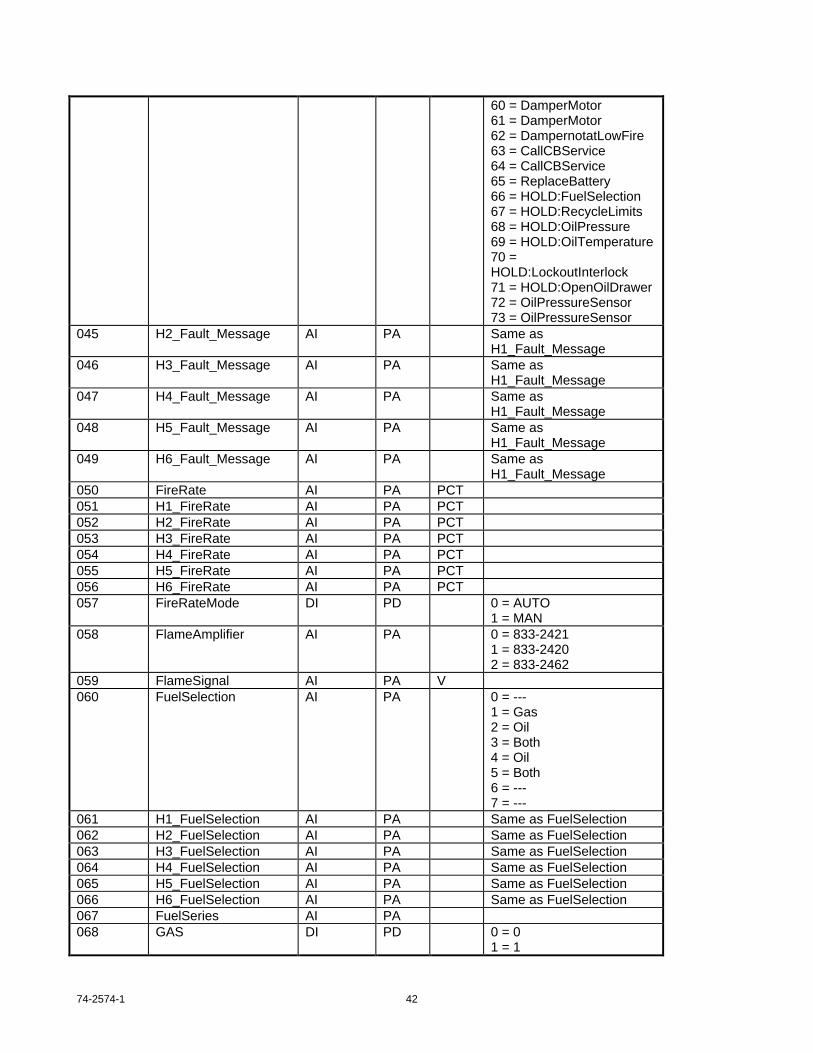
60 = DamperMotor61 = DamperMotor62 = DampernotatLowFire63 = CallCBService64 = CallCBService65 = ReplaceBattery66 = HOLD:FuelSelection67 = HOLD:RecycleLimits68 = HOLD:OilPressure69 = HOLD:OilTemperature70 =HOLD:LockoutInterlock71 = HOLD:OpenOilDrawer72 = OilPressureSensor73 = OilPressureSensor
045 H2_Fault_Message AI PA Same asH1_Fault_Message
046 H3_Fault_Message AI PA Same asH1_Fault_Message
047 H4_Fault_Message AI PA Same asH1_Fault_Message
048 H5_Fault_Message AI PA Same asH1_Fault_Message
049 H6_Fault_Message AI PA Same asH1_Fault_Message
050 FireRate AI PA PCT051 H1_FireRate AI PA PCT052 H2_FireRate AI PA PCT053 H3_FireRate AI PA PCT054 H4_FireRate AI PA PCT055 H5_FireRate AI PA PCT056 H6_FireRate AI PA PCT057 FireRateMode DI PD 0 = AUTO
1 = MAN058 FlameAmplifier AI PA 0 = 833-2421
1 = 833-24202 = 833-2462
059 FlameSignal AI PA V060 FuelSelection AI PA 0 = ---
1 = Gas2 = Oil3 = Both4 = Oil5 = Both6 = ---7 = ---
061 H1_FuelSelection AI PA Same as FuelSelection062 H2_FuelSelection AI PA Same as FuelSelection063 H3_FuelSelection AI PA Same as FuelSelection064 H4_FuelSelection AI PA Same as FuelSelection065 H5_FuelSelection AI PA Same as FuelSelection066 H6_FuelSelection AI PA Same as FuelSelection067 FuelSeries AI PA068 GAS DI PD 0 = 0
1 = 1

43 74-2574-1
069 GasPressure AI PA070 GasPressureSensor AI PA V071 GasSensRange AI PA072 GMV DI PD 0 = 0
1 = 1073 HiGasLimit AI PA074 HiOilPressLimit AI PA V075 HiOilTempLimit AI PA DF076 HVO DI PD 0 = 0
1 = 1077 KeyboardMode AI PA 0 = PROGRAM
1 = OPERATE078 LoFire AI PA PCT079 LoGasLimit AI PA080 LOI DI PD 0 = 0
1 = 1081 LoOilPressLimit AI PA PSI082 LoOilTempLimit AI PA DF083 LTO DI PD 0 = 0
1 = 1084 ManualFireRate AI PA POS085 MajorRevision AI PA086 MaxFire AO PA PCT087 MinorRevision AI PA088 NomGasPress AI PA PSI089 NomOilPress AI PA PSI090 NomOilTemp AI PA DF091 OilPressSensRange AI PA PSI092 OilPressure AI PA PSI093 OilPressureSensor AI PA V094 OilTemperature AI PA DF095 OilTempSensor AI PA OHM096 OilTempSensRange AI PA DF097 OMV DI PD 0 = 0
1 = 1098 OperPressure AI PA PSI099 OperSetpoint AO PA DF100 OperTemperature AI PA DF101 PII AI PA102 PostpurgeExtend AI PA SEC103 PrepurgeExtend AI PA SEC104 ProgramIdent AI PA 0 = CB-2000
1 = CB-20012 = CB-2002
105 PV DI PD 0 = 01 = 1
106 RateLinearization AI PA107 Response AO PA108 RLIM DI PD 0 = 0
1 = 1109 SequenceTimer AI PA SEC110 H1_SequenceTimer AI PA SEC111 H2_SequenceTimer AI PA SEC

74-2574-1 44
112 H3_SequenceTimer AI PA SEC113 H4_SequenceTimer AI PA SEC114 H5_SequenceTimer AI PA SEC115 H6_SequenceTimer AI PA SEC116 Setback_Capable AI PA 0 = Unprogrammed
1 = No2 = Yes
117 Setback_Mode DO PD 0 = No1 = Yes
118 SetbkBoilerOff AO PA DF119 SetbkBoilerOn AO PA DF120 SetbackSetPt AO PA DF121 SteamSensRange AI PA PSI122 StmPressSensor AI PA V123 Total_Cycles AI PA124 Total_Hours AI PA HR125 WaterSensRange AI PA DF126 WtrTempSensor AI PA OHM
List Other OpenLink Controller Points
Some points in the OpenLink Controller CPU might not be mapped to a specific Q7700 controller point, and therefore thesepoints will not belong specifically to the CARE plant that represents the Q7700 controller. There may also be points that arethe results of calculations done in Control Strategy or Switching Logic in the OpenLink Controller CPU. These points shouldgo into an OpenLink plant that is named after the OpenLink Controller for clarity. If you need to configure any Q7700 sub-network control sequences, the OpenLink plant is a good place for it.
Determine the Number of OpenLink Controllers Required
Based on the I/O summaries and the size of the Q7700 network, more than one OpenLink Controller may be necessary.Only one OpenLink Controller is allowed on any Q7700 network, however, so if more than one OpenLink Controller isneeded, the Q7700 networks must be separated. See the OpenLink Controller CPU / CARE Tool Application Notes for theOpenLink Controller point limitations.
Plan the Controller Bus Architecture
If necessary, draw a schematic of the two networks to plan wiring and aid in the installation, checkout and test of thesystem.C-Bus wiring guidelines are described below; this guide does not contain any information on Q7700 network wiring.
C-Bus Wiring Guidelines
The OpenLink Controller follows the same wiring rules as other C-Bus controllers. Recommended wiring types are:
• AK3702: Use unshielded twisted pair cable AK3702 as the primary non-plenum cable for all data speeds. (Belden 9571)
• AK3740A: Use this shielded cable to minimize the cost for shielded cable applications. (Belden 9574)
• Belden 9841: Use this shielded cable to maximize the cable distance for shielded non-plenum cable applications at921.6 KBPS.
C-Bus Communication Submodule Types
The XD505 and XD505A are electrically identical (on the bus). Neither has bus termination capability. Both have 4.7K pullup/down biasing that can not be disabled. These submodules support data rates of 4.8/9.6 KBPS

45 74-2574-1
The XD508 is capable of combining termination (118 Ohm) and biasing (1K Ohm pull up/down) for the C-Bus cable forends. It operates at baud rates of 4.8/9.6/19.2/38.4/76.8/921.6 KBPS; bus throughput, however, does not increase beyond76.8 KBPS.
The XD508s and XD505/505As can not be intermixed on the same bus.
Maximum C-Bus Length
The maximum length for the C-Bus is 4000 feet [1440 m] without a repeater. A high speed repeater can be used to lengthenthe bus beyond 4000 feet. Refer to Excel High Speed Repeater Checkout and Test 74-5024.
The bus cable length is measured from the first device (OpenLink Controller, XBS, XL600/500/100/80, or repeater) andincludes all bus wiring between each device until the last device (or the next repeater).
Recommended C-Bus Wiring Layout
The only acceptable arrangement for C-Bus layout is a single daisy chain arrangement to each controller. A daisy chain hasonly one starting node and one ending node (regardless of where the OpenLink Controller is located).
With a single daisy chain installation, the risk of unwanted reflections occurring is greatly reduced. Unwanted reflectionscould cause no-responses/missed messages on the bus.
C-Bus End of Line (termination) Resistors
If a bus has 15 or less XD505/505A submodules, always terminate the bus at both ends.
If a bus has 16 or more XD505/505A submodules, terminate one end only, preferably the end that is farthest from the nextdevice.
When using XD508 submodules on the bus, termination is always required at both ends and can be accomplished byturning on the submodule dip-switches at the end devices.
In the case of Excel 100/80 devices, termination can be accomplished by connecting terminals 31 to 34 and 32 to 35. ForExcel 600/500 devices, connect terminals 13 to 16 and 14 to 17. For the Excel Link Controller, connect terminals 20 to 23and 21 to 24. For the OpenLink Controller, connect terminals 9 to 10 and 11 to 12. For the Excel Building Supervisor,enable the resistor jumper on the XPC500 board. See the Excel Building Supervisor or the specific controller checkout andtest literature for further details.
Never leave the bus completely unterminated.
C-Bus Shielding
Use only unshielded cable types unless:
• The customer has specifically requested the use of shielded cable.
• The bus wiring is in a high EMI environment and not inside a dedicated metallic conduit.
Connect the shield through each device, and attach one end to the local earth ground.
Do not connect the shield to the controller common terminals.
OpenLink Controller Wiring Overview
.

74-2574-1 46
Fig. 2. OpenLink Controller Sub-base Terminals for E3-0 or P1-0 Motherboard.
Excel 500 OpenLink connection to Q7700 System.
QS7850
BUS A B C
QS7850
BUS A B C
Excel 5000 Openlink
VNI BUS 65+ 66-
72
71
70
69
68
67
66
65
64
63
62
61
60
59
58
57
56
55
VNI BUS +
VNI BUS -
36
35
34
33
32
31
30
28
26
25
24
29
23
22
21
20
19
27
EARTH GROUND
24 VAC
24 VAC
TO C-BUSC-BUS -
C-BUS +
SHIELD
SHIELD
NOTE:THE SWITCH ON THEC-BUS XD508 BOARD MUST BE IN THE ONPOSITION, IF Q9200A IS AT THE ENDOF THE BUS. THIS ENABLES THE EOL AND BIASING RESISTORS. OTHERWISE IT SHOULD BE OFF.
(THE C-BUS XD508 IS THE DAUGHTERBOARD WHICHIS FARTHEST FROMTHE BATTERY)
NOTE:THE SWITCH ON THEVNI XD508 BOARD MUST BE IN THE ON POSITION. THIS ENABLES THE EOLAND THE BIASINGRESISTORS.
(THE VNI XD508 IS THEDAUGHTERBOARD WHICH IS CLOSEST TO THE BATTERY)
23

47 74-2574-1
Step 2: Order Hardware and Software
For a complete OpenLink Controller system for a Q7700 application, order:
A Q9200A1002 OpenLink Controller Assembly, specify XD505A or XD508 C-Bus Communication Daughterboard, TheXD508 will ship by default.A power supply module with cable (or a dedicated transformer with fused disconnect),CARE Software,a serialized protection plug and diskette.
The ZM5002 software and all necessary Q7700 software and firmware are included.
The PC used for configuring the OpenLink Controller must have MS-DOS and Windows software already installed. Otherparts for the system, such as operators terminals, enclosures, etc., are optional.
Hardware
Order FromPart No. Equipment/Item Installed
SystemsAppliedSystem
Q9200A1002 OpenLink Controller Assy for Q7700 SPE ASD14507287-001 120 VAC Power Supply Module AHF ASD14507287-004 240/220 VAC Power Module AHF ASD14507063-003 Cable for OpenLink Controller to Power Module AHF ASDXD505A or XD508 C-Bus Communication Daughterboard AHF ASDXI582AH Operator Terminal, desktop, backlit AHF ASDXW565 Cable for XI582 (16 ft.) AHF ASDXW566 Cable for XI582 (49 ft.) AHF ASD14506635-002 Full size General Purpose Enclosure AHF ASD14506635-001 Half size General Purpose Enclosure AHF ASD14506636-002 Full size General Purpose Door AHF ASD14506636-001 Half size General Purpose Door AHF ASDXW567 Cable for PC to B-port communication AHF ASD
SPE - Special Projects, Arlington HeightsAHF - Arlington Heights FactoryASD - Authorized Systems DistributorNOTE: Contractors must order equipment from their Authorized Systems Distributor (ASD).
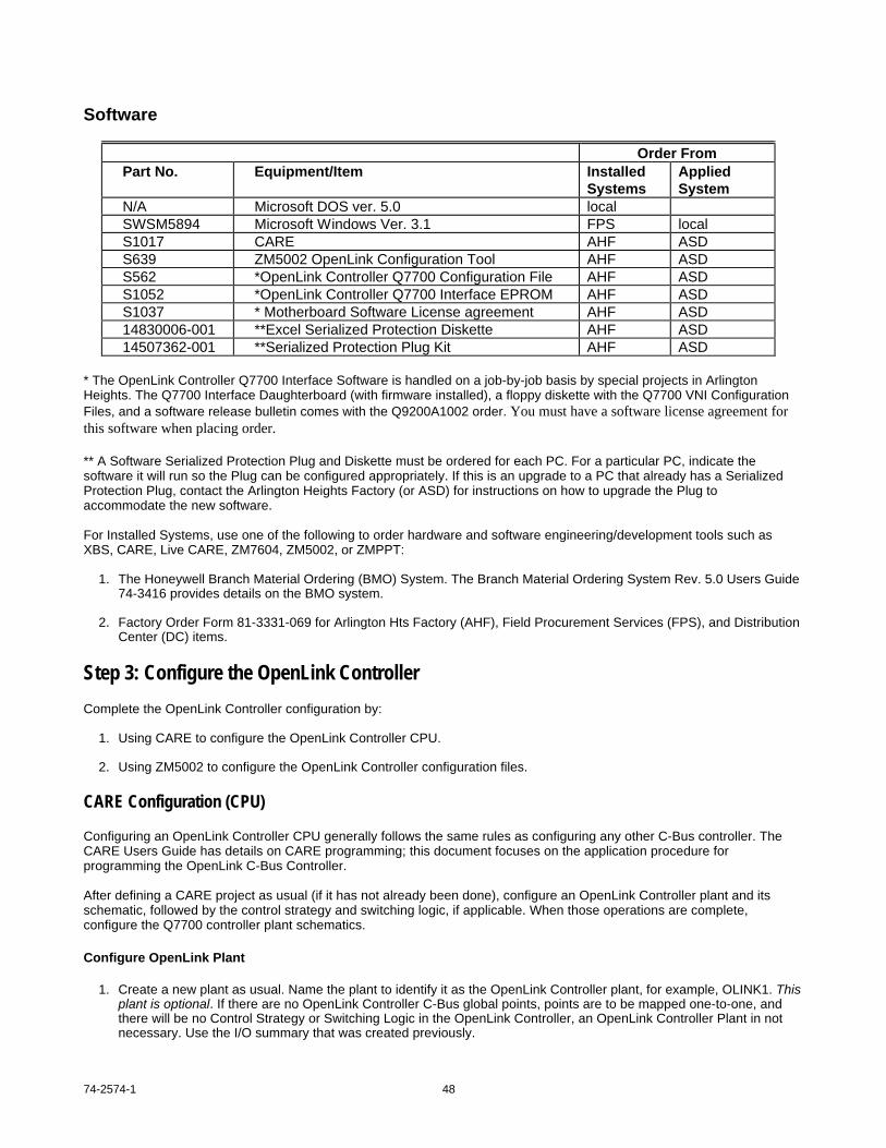
74-2574-1 48
Software
Order FromPart No. Equipment/Item Installed
SystemsAppliedSystem
N/A Microsoft DOS ver. 5.0 localSWSM5894 Microsoft Windows Ver. 3.1 FPS localS1017 CARE AHF ASDS639 ZM5002 OpenLink Configuration Tool AHF ASDS562 *OpenLink Controller Q7700 Configuration File AHF ASDS1052 *OpenLink Controller Q7700 Interface EPROM AHF ASDS1037 * Motherboard Software License agreement AHF ASD14830006-001 **Excel Serialized Protection Diskette AHF ASD14507362-001 **Serialized Protection Plug Kit AHF ASD
* The OpenLink Controller Q7700 Interface Software is handled on a job-by-job basis by special projects in ArlingtonHeights. The Q7700 Interface Daughterboard (with firmware installed), a floppy diskette with the Q7700 VNI ConfigurationFiles, and a software release bulletin comes with the Q9200A1002 order. You must have a software license agreement forthis software when placing order.
** A Software Serialized Protection Plug and Diskette must be ordered for each PC. For a particular PC, indicate thesoftware it will run so the Plug can be configured appropriately. If this is an upgrade to a PC that already has a SerializedProtection Plug, contact the Arlington Heights Factory (or ASD) for instructions on how to upgrade the Plug toaccommodate the new software.
For Installed Systems, use one of the following to order hardware and software engineering/development tools such asXBS, CARE, Live CARE, ZM7604, ZM5002, or ZMPPT:
1. The Honeywell Branch Material Ordering (BMO) System. The Branch Material Ordering System Rev. 5.0 Users Guide74-3416 provides details on the BMO system.
2. Factory Order Form 81-3331-069 for Arlington Hts Factory (AHF), Field Procurement Services (FPS), and DistributionCenter (DC) items.
Step 3: Configure the OpenLink Controller
Complete the OpenLink Controller configuration by:
1. Using CARE to configure the OpenLink Controller CPU.
2. Using ZM5002 to configure the OpenLink Controller configuration files.
CARE Configuration (CPU)
Configuring an OpenLink Controller CPU generally follows the same rules as configuring any other C-Bus controller. TheCARE Users Guide has details on CARE programming; this document focuses on the application procedure forprogramming the OpenLink C-Bus Controller.
After defining a CARE project as usual (if it has not already been done), configure an OpenLink Controller plant and itsschematic, followed by the control strategy and switching logic, if applicable. When those operations are complete,configure the Q7700 controller plant schematics.
Configure OpenLink Plant
1. Create a new plant as usual. Name the plant to identify it as the OpenLink Controller plant, for example, OLINK1. Thisplant is optional. If there are no OpenLink Controller C-Bus global points, points are to be mapped one-to-one, andthere will be no Control Strategy or Switching Logic in the OpenLink Controller, an OpenLink Controller Plant in notnecessary. Use the I/O summary that was created previously.

49 74-2574-1
If a plant is necessary, select any plant type for the OpenLink Controller Plant. This Plant is used to configure pointsthat need to be located in the OpenLink Controller CPU but do not map directly to Q7700 points. C-Bus global pointsin the OpenLink Controller CPU and points that are the results of calculations done in the OpenLink Controller ControlStrategy, belong in this Plant. Any Q7700 network control sequences can go in this plant.
This plant does not represent a specific Q7700 controller; those plants are discussed in the next section.
2. Create a plant schematic as usual.
Represent your physical points here. Pseudo points need to be created in the Control Strategy or Switching Logic.Use (points without graphic) if desired.
3. Control Strategy sequences can reside in this plant (optional step). If C-Bus global points are used in the OpenLinkController CPU, they can not be directly mapped to Q7700 controller points. The global point must run into an IDTicon and out to a pseudo point and then the pseudo point must be mapped to the Q7700 point. Another point that canbelong to the OpenLink Controller Plant, rather than a specific plant representing a Q7700 controller, is a minimum (ormaximum or average) space temperature point. To calculate and view the minimum of all the Q7700 controller spacetemperatures at the XBS operator interfaces, simply re-create these same points in the OpenLink Controller plant, doa minimum function to them, and create the resultant pseudo analog software point. (All the space temperature pointsalready exist in the other plants.)
4. Switching logic rules are the same for the OpenLink Controller plants as they are for other CARE plants (optionalstep). This is a good place to program OpenLink Controller plant pseudo points.
Configure Q7700 Plants
1. Create a new plant as usual. It is necessary to create one CARE Q7700 plant for each of the Burner/Boiler controllersin the Q7700 network. Give these plants the same names as were given to the controllers when the I/O Summary wascompiled. If there are many Q7700 controllers with identical I/O Summaries, save time by configuring a template plantof one controller and use the (Replicate Plant) feature.
Pick the Plant Type which most closely represents the function of the Q7700 Burner/Boiler controller.
2. Create a Plant Schematic as usual. Use the Schematic Segments (or points without graphics) to build arepresentation of the Q7700 controllers physical I/O points; include only the points listed in the I/O Summary. Eachpoint contained in the Q7700 Plants should be mapped. Every point in the I/O Summary should be represented hereor, in the case of software points, in the Control Strategy or Switching Logic (since pseudo points can not be createdin the schematic).
3. Control Strategy sequences can reside in this plant as they can in other CARE plants (optional step). Since theQ7700 controllers already contain their own control programming, providing Control Strategy here is not common. Ifsome OpenLink Controller Control Strategy must be done using Q7700 controller input/output points, be aware of thepossible time delay and the fact that if the OpenLink Controller goes down so do these control strategy computations.
4. Switching logic rules are the same for Q7700 plants as for other plants (optional step). This is a good place toprogram Q7700 plant pseudo points. Create them, but don’t save the Switching Table. The points will remain.
Replicate Q7700 Plants
If more than one Q7700 controller has the same I/O Summary, use the CARE Replicator to mass produce plants and savetime. The replicator appends each user address in the plant with the Plant Name. This feature may or may not be desirable,however, it must be planned for. See the CARE Users Guide for step-by-step procedures on replicating.
Attach Plants
Attach the OpenLink Controller plant (if applicable) and all the Q7700 plants (except any template plants) to the OpenLinkController. Create a new controller to represent the new OpenLink Controller. To do this, select Controller/New and fill inthe Controller Name, Number, and select type, XLINK. Initial releases of CARE do not contain an OpenLink controller toattach to. Because the Excel Link Controller and the OpenLink Controller have similar CPUs, this is not a problem.
Note: The attach process is when all the OpenLink Controller points get index numbers assigned to them. All mappablepoints get an MA Index with a range of 0-767. The mapper, described in the section Using the ZM5002 OpenLinkConfiguration Tool, uses this MA Index as a key to pairing up points. It is important to note this because if a plant is

74-2574-1 50
detached its points must be re-mapped. All OpenLink Controller global points get the normal default technicaladdresses assigned; they do not get an MA index (which is why they can not be mapped).
Edit Miscellaneous Text
Edit miscellaneous text the same as for any other controller, with the following exception:
Set up simple linear I/O Characteristics for the OpenLink Controller CPU's physical points that cover the point value span asshown in the Q7700 controller point tables earlier in this manual. Do not use a non-linear I/O Characteristic for a Q7700point. For example, the default I/O Characteristic of “Linear 0-100” would be fine for a point with values between 0 and 14,but would not cover a point with a span of 0-155. Do not use an I/O Characteristic such as 0-100,000 for a point that is onlygoing to vary from 0 to 100; resolution will be lost.
Edit Data Points
Edit data points the same as any other controller except:
• Alarm Delays: All CARE points that are mapped to a Q7700 alarming point must have the CARE Data Point Editor AlarmDelay attribute set to ZERO seconds. This rule applies to digital alarm points and analog input points with high and lowlimits.
• I/O Characteristic: Choose the I/O characteristic that has a span covering the range of the mapped Q7700 point value.Do not choose non-linear I/O Characteristics. See the tables in Step 1 for possible point ranges.
• Make sure that the I/O Characteristic bounds for an analog output, and the alarm limits for a pseudo analog are EQUALto the high and low values for the commandable output points listed in the Q7700 controller point tables. These valuesare the “clipping” values that prevent the user from commanding a Q7700 point outside of its allowable range.
Edit Time Programs
Set up time programs the same as other C-Bus controllers. The user may use time program points to set the Q7700controllers to occ/unocc mode. See the Q7700 controller point tables for the appropriate output points to command.
Translate OpenLink Controller
Translate the OpenLink Controller the same as other C-Bus controllers. The translator generates code for the OpenLinkController CPU.
Print CARE Documentation
Print out the CARE Documentation the same as other C-Bus controllers.
Back up CARE Project
Backing up the CARE project is not required unless the PC on which CARE configuration is performed is different than thePC that will be used to download the OpenLink Controller in the field. A current project backup is highly recommendedhowever.
ZM5002 Configuration (OpenLink Controller Configuration Files)
The ZM5002 OpenLink Configuration Tool is used mainly to define the Q7700 network points that need to be mapped to C-Bus points. See the ZM5002 Users Guide for details on the procedure. A general description of the procedure follows andcontains information on how to apply the tool for a Q7700 Sub-Network. To use the ZM5002 Tool, exit CARE and doubleclick on the ZM5002 OpenLink Controller icon. Select the Project and OpenLink controller to be defined. At this point, anOpenLink Controller may be restored if applicable.
Define Sub-Network Controllers and Points
1. For each OpenLink Controller, define each Burner/Boiler controller on the sub-network (using the I/O Summaries thatwere previously assembled.

51 74-2574-1
a. Each Burner/Boiler controller entry has a generic name (use the name on the I/O Summary for clarity), aspecific model or type (for example, RM7800 ), a 7850 address ( this is the address of the Q7700 the device isoff of ) and an address (1-6 ) for the Q7700 SLOT field.
Note that for the multidrop S7810B configuration ONLY( This is the configuration that allowsmultiple RM7800’s to talk through one physical slot) , the slot number will be the number that wasprogrammed by the CSM utility. This is sometimes referred to as the subnetwork number.
b. When the user defines a controller and adds it to the list box, all of that controller’s mappable points areavailable for mapping in the next step.
2. The Setup text box for Q7700 Sub-Networks contains the following four fields:
a. The request response time, in 1/10ths of a second. OpenLink waits this long for Q7700 controllers toacknowledge a request from the OpenLInk. When a controller does not respond, the OpenLink tries three moretimes. If there are nuisance “point no response messages” (Link Point Alarm, critical alarms on the C-Bus), itmay be necessary to increase this field. Only increase this value until the nuisance alarm messages areresolved.
b. The point response time, in 1/10ths of a second. OpenLink waits this long for Q7700 points to respond , afterthe acknowledge has been received, before re-trying the point. When a point does not respond, the OpenLinktries three more times. If there are nuisance “point no response messages” (Link Point Alarm, critical alarms onthe C-Bus), it may be necessary to increase this field. Only increase this value until the nuisance alarmmessages are resolved.
c. The Sub-Network baud rate (default = 0096, 9600 baud).
d. The number of points that are in no response on a controller before marking the controller “down”, andthe number of points scanned on a down controller in each periodic cycle. The points on a down controllerwill be in “no response,” but the OpenLink has to keep checking points to see when the controller comes backon line. As soon as a single point responds to the OpenLink Controller, that controller is considered to be backon line. The range is 00 to 09. A value of 00 means all the points are read on a down controller. If the user isdoing any network control sequences that require fast reaction, this number should be set to a low number like2 or 3. See the section in this manual on “OpenLink Performance” for more details on the periodic cycle andpoint handling. This value is defined by BYTE 20 of the setup field.
Map Points and Engineering Units
1. In the Map Points window, map each pair of points pair by pair. One list box list all the points that were created inCARE and attached to the OpenLink Controller. Another list box lists all the mappable Q7700 points, by controller. Tomap points, highlight one point in the CARE User Addresses list box and highlight one point in the Sub-NetworkController/Points list box and then click Add. The mapped pair then appears in a third list box.
a. If necessary Remove a pair of points or Delete the whole mapping table. Selecting OK saves the mappingtable.
b. If an attempt is made to map incompatible points (for example a digital to an analog), a warning will appear.
2. Use the Map Engineering Units window to convert engineering units from English to Metric or Metric to English(optional step). This can be done across the board by selecting Automap, or it can be done selectively. All points of agiven engineering unit on a network are converted if that conversion is selected. (The user can not select specificpoints for conversion if other point also have the same engineering units.)
Cross - Check for Errors
After point mapping and engineering unit mapping is complete, always perform a cross-check to look for errors.
Print ZM5002 Documentation
Print out a hard copy of the OpenLink Controller configuration. It is not required, but is useful for submittal purposes, the jobfile, training purposes, etc. The printout contains all the work done in ZM5002.
Back up OpenLink Controller Configuration

74-2574-1 52
Maintaining a current back up of the OpenLink Controller configuration is recommended. Leave a current OpenLinkController backup with the controller, or the person responsible for maintaining the controller. The ZM5002 OpenLinkController Configuration Tool does not have an upload feature, so future modifications to the OpenLink Controllerconfiguration rely on a current back up.
Now that the OpenLink Controller has been completely configured using the CARE and ZM5002 Configuration Tools it isready for downloading. For details on installation, downloading, checkout and test, see the OpenLink ControllerInstallation/Checkout and Test manual.

Home and Building Control Home and Building Control Home and Building Control ProductsHoneywell Inc. Honeywell Limited-Honeywell Limitee Honeywell AGHoneywell Plaza 155 Gordon Baker Road Böblinger Straße 17P.O. Box 524 North York Ontario D-71101 SchönaichMinneapolis, MN 55408-0524 M2H 3N7 Phone (49-7031) 637-01
Fax (49-7031) 637-493
Electronic document only74-2574-1 Feb 2000 www.honeywell.com