7.1 friction: basic applications - civil engineering friction: basic applications example 1, ......
TRANSCRIPT
7.1 Friction: Basic Applications

7.1 Friction: Basic Applications Example 1, page 1 of 2
Equations of equilibrium:
F x = 0: N
B f A = 0
F y = 0: N
A 98.1 N = 0
M A = 0: (98.1 N)(0.5 m) N
B(1.732 m) = 0
+
+
+
6
1. The uniform ladder is 2-m long and makes an angle of = 60
with the floor. If the wall at B is smooth and the coefficient of
static friction at A is A = 0.3, determine if the ladder can remain
in the position shown.
A
B
Mass of ladder = 10 kg
1 m
1 m
N B
N A
f A
(2 m)(sin 60°) = 1.732 m
Results of solving the above
equations of equilibrium:
N A = 98.1 N
N B = 28.3 N
f A = 28.3 N
7
Free-body diagramNo friction force is
present because the
wall is smooth.
Because the ladder is
uniform, the weight
acts through the center.
Weight = mg
= (10 kg)(9.81 m/s2 )
= 98.1 N
The friction force must
be drawn in a direction
opposing the
impending motion.
60°
12
3
5
4 Impending motion
A
B
(1 m)(cos 60°) = 0.5 m
7.1 Friction: Basic Applications Example 1, page 2 of 2
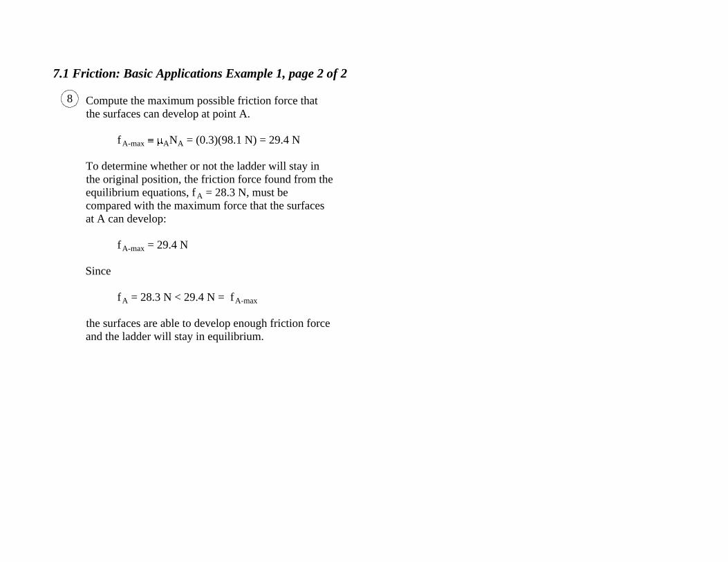
Compute the maximum possible friction force that
the surfaces can develop at point A.
f A-max
AN A = (0.3)(98.1 N) = 29.4 N
To determine whether or not the ladder will stay in
the original position, the friction force found from the
equilibrium equations, f A = 28.3 N, must be
compared with the maximum force that the surfaces
at A can develop:
f A-max = 29.4 N
Since
f A = 28.3 N < 29.4 N = f
A-max
the surfaces are able to develop enough friction force
and the ladder will stay in equilibrium.
8

7.1 Friction: Basic Applications Example 2, page 1 of 2
Equations of equilibrium:
F x = 0: N
B f A = 0 (1)
F y = 0: N
A 98.1 N = 0 (2)
M A = 0: (98.1 N)(1 m) cos N
B(2 m) sin = 0 (3)
+
+
+
5
2. The uniform ladder is 2-m long and the wall at B
is smooth. If the coefficient of static friction at A is
A = 0.2, determine the smallest angle for which
the ladder can remain in the position shown.
A
B
Mass of ladder = 10 kg
1 m
1 m
N B
N A
f A
Three equations, but four unknowns: N B, f
A, N A, and
An additional equation is needed.
6
Free-body diagram
No friction force is
present because the
wall is smooth.
The friction force
must be drawn in a
direction opposing the
motion.
1
2
4
3 Impending motion
(1 m) cos
(2 m) sin
Weight = mg
= (10 kg)(9.81 m/s2 )
= 98.1 N

7.1 Friction: Basic Applications Example 2, page 2 of 2
The fourth equation comes from the condition of
impending slip at point A, because if slip is just about to
occur, then the friction force, f A, is at its maximum value,
which is ANA:
f A f
A-max AN
A = (0.2)N A (4)
Three of the four equations are linear but the moment
equation, Eq. 3, is nonlinear because cos and sin
appear.
M A = 0: (98.1 N)(1m) cos
- N B(2 m) sin = 0 (Eq. 3 repeated)
The easiest way to solve these equations is to use the
general equation solver on a calculator. Alternatively,
manipulate the equations as follows.
First note that Eq. 2 implies that
N A = 98.1 N
Then using this value for N A in Eq. 4 gives
f A = N
A
= (0.2)(98.1 N)
= 19.62 N
+Using f
A = 19.62 N in Eq. 1 gives
N B = f
A
= 19.62 N
Using N B = 19.62 N in Eq. 3 gives
(98.1 N) cos (19.62 N)(2) sin = 0
Dividing through by cos and rearranging gives
Replacing the left-hand side of this equation by tan
gives
tan = 2.5
which implies
68.2 Ans.
8
sin 98.1cos (19.62)(2)
= = 2.5
7
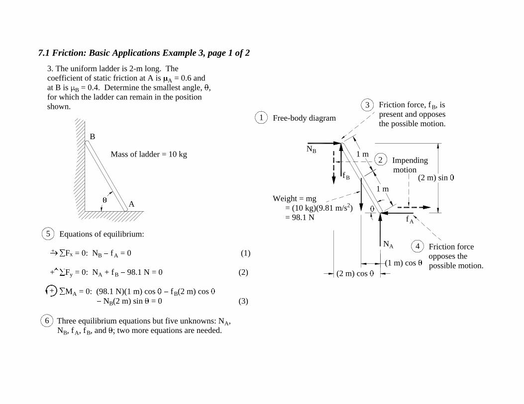
7.1 Friction: Basic Applications Example 3, page 1 of 2
Equations of equilibrium:
F x = 0: N
B f A = 0 (1)
F y = 0: N
A + fB 98.1 N = 0 (2)
M A = 0: (98.1 N)(1 m) cos f
B(2 m) cos
N B(2 m) sin = 0 (3)
+
+
Mass of ladder = 10 kg
B
A
3. The uniform ladder is 2-m long. The
coefficient of static friction at A is A = 0.6 and
at B is B = 0.4. Determine the smallest angle, ,
for which the ladder can remain in the position
shown.
+
5
1 m
1 m
N B
N A
f A
Three equilibrium equations but five unknowns: N A,
N B, f
A, f B, and two more equations are needed.
6
Free-body diagram
Friction force, f B, is
present and opposes
the possible motion.1
3
4
(2 m) sin f B
Friction force
opposes the
possible motion.
(2 m) cos
(1 m) cos
Impending
motion
2
Weight = mg
= (10 kg)(9.81 m/s2 )
= 98.1 N
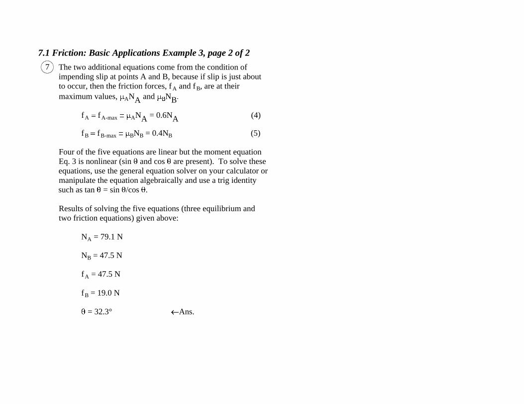
7.1 Friction: Basic Applications Example 3, page 2 of 2
The two additional equations come from the condition of
impending slip at points A and B, because if slip is just about
to occur, then the friction forces, f A and f
B, are at their
maximum values, AN
A and N B
f A f
A-max AN
A = 0.6N A (4)
f B f
B-max BN
B = 0.4N B (5)
Four of the five equations are linear but the moment equation
Eq. 3 is nonlinear (sin and cos are present). To solve these
equations, use the general equation solver on your calculator or
manipulate the equation algebraically and use a trig identity
such as tan = sin /cos .
Results of solving the five equations (three equilibrium and
two friction equations) given above:
N A = 79.1 N
N B = 47.5 N
f A = 47.5 N
f B = 19.0 N
= 32.3° Ans.
7
7.1 Friction: Basic Applications Example 4, page 1 of 3
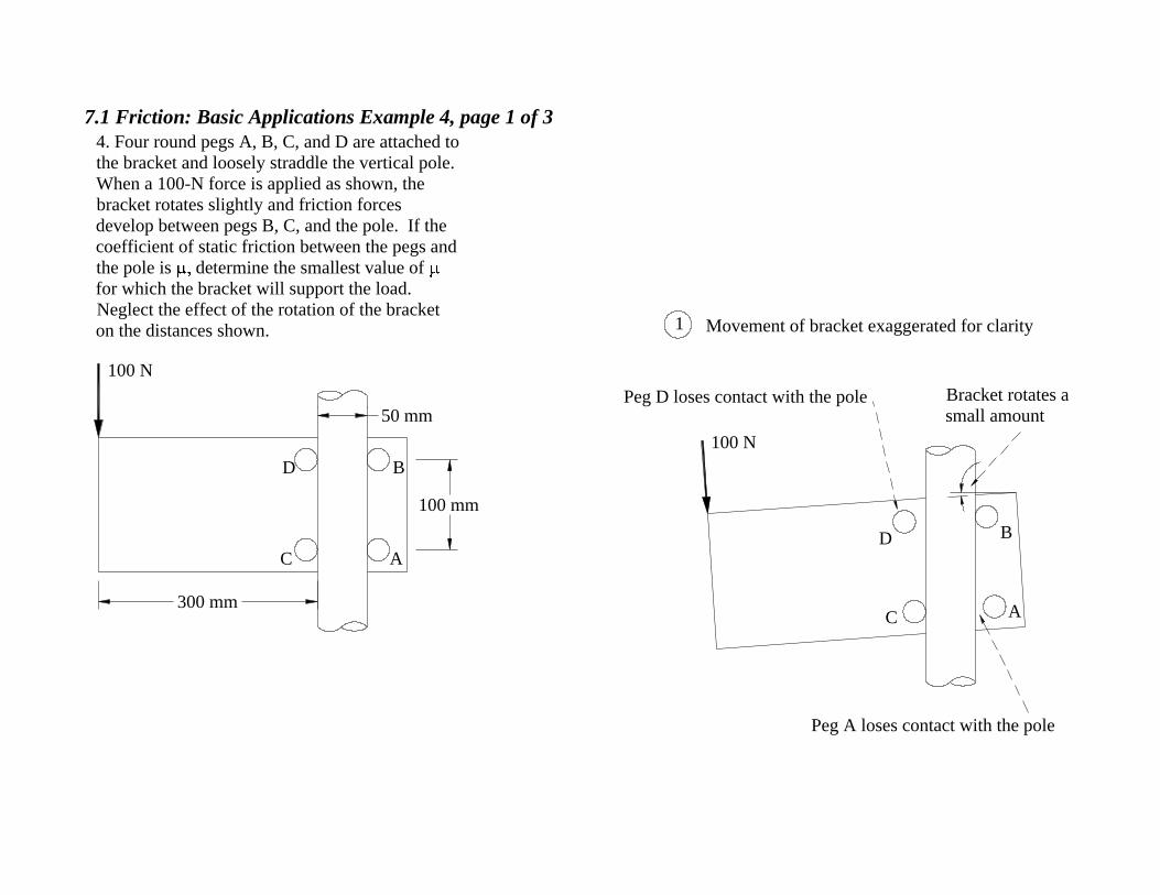
4. Four round pegs A, B, C, and D are attached to
the bracket and loosely straddle the vertical pole.
When a 100-N force is applied as shown, the
bracket rotates slightly and friction forces
develop between pegs B, C, and the pole. If the
coefficient of static friction between the pegs and
the pole is determine the smallest value of
for which the bracket will support the load.
Neglect the effect of the rotation of the bracket
on the distances shown.
100 N
A
B
C
D
300 mm
50 mm
100 mm
Bracket rotates a
small amount
Peg A loses contact with the pole
Movement of bracket exaggerated for clarity1
100 N
D B
AC
Peg D loses contact with the pole

7.1 Friction: Basic Applications Example 4, page 2 of 3
2
P = 100 N
100 mmf B
N B
N C
f C
Free-body diagram
300 mm 50 mm
Impending
motion of
bracket
3
The friction forces, f B and f
C,
resist the motion by pushing the
bracket up.
4
As the bracket inclines slightly, the pegs at A and D
lose contact with the pole. That is why no forces
appear at A and D on the free-body diagram.
Equations of equilibrium:
F x = 0: N
B N C = 0 (1)
F y = 0: f
B + f C 100 N = 0 (2)
MC = 0: (100 N)(300 mm) + f B(50 mm)
N B(100 mm) = 0 (3)
++
+
7
6
The normal forces,
N B and N
C, are
directed from the
pole to the pegs .
5
B
C

7.1 Friction: Basic Applications Example 4, page 3 of 3
There are only three equations of equilibrium but four
unknowns (f B, N
B, f C, and N
C), so at least one more
equation is needed. The additional equation comes from the
condition of impending slip at B, but if the bracket is going
to slip at B, it will also slip at C. So we have two additional
equations and one additional unknown, :
f B = f
B-max N B (4)
f C = f
C-max N C (5)
Solving Eqs. 1-5 gives the results below (Note that Eqs. 4
and 5 are nonlinear because multiplies N B and N
C):
f B = 50 N
N B = 325 N
f C = 50 N
N C = 325 N
= 0.154 Ans.
8
7.1 Friction: Basic Applications Example 5, page 1 of 2
M
O y
O x
200 mm
N B
f B
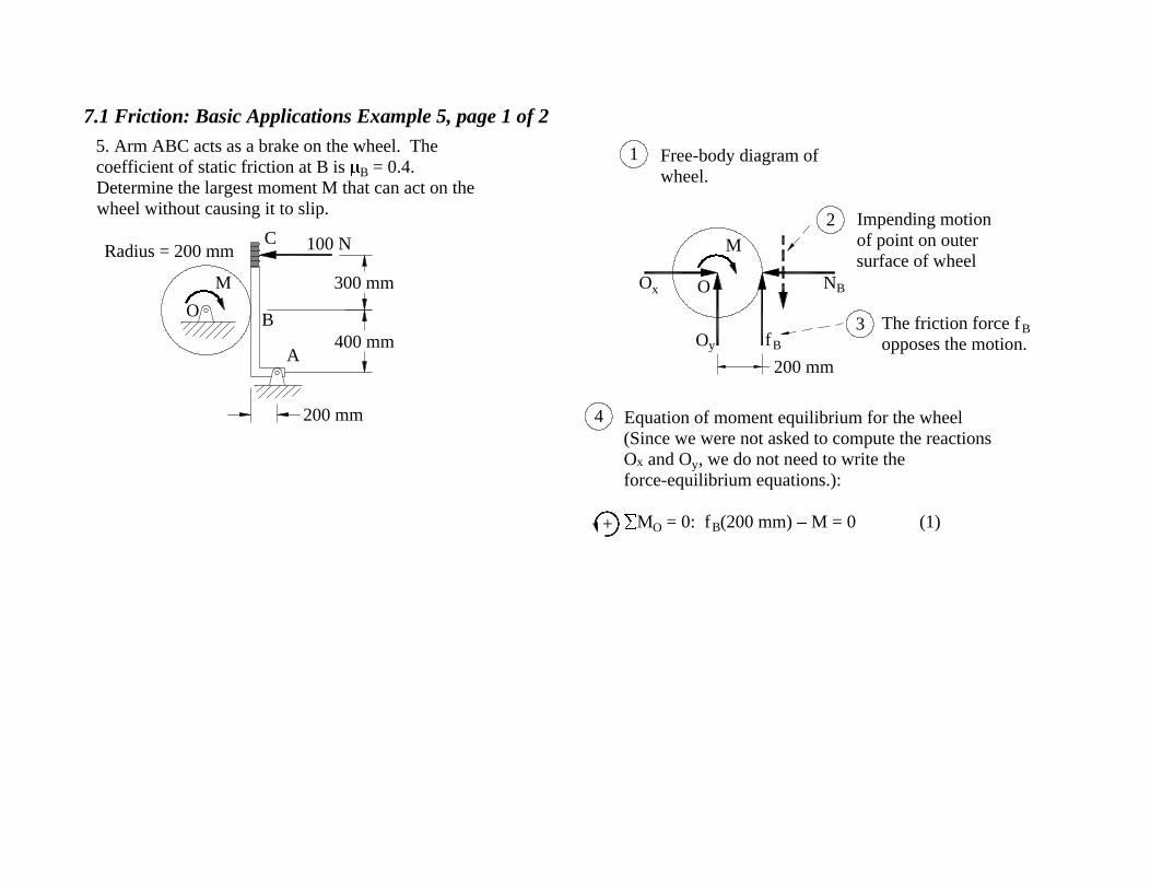
Free-body diagram of
wheel.
1
Impending motion
of point on outer
surface of wheel
The friction force f B
opposes the motion.
2
3
Equation of moment equilibrium for the wheel
(Since we were not asked to compute the reactions
O x and O
y, we do not need to write the
force-equilibrium equations.):
M O = 0: f
B(200 mm) M = 0 (1)
4
+
O
200 mm
Radius = 200 mm 100 NC
300 mm
400 mm
B
A
M
O
5. Arm ABC acts as a brake on the wheel. The
coefficient of static friction at B is B = 0.4.
Determine the largest moment M that can act on the
wheel without causing it to slip.
7.1 Friction: Basic Applications Example 5, page 2 of 2
The third equation follows from the condition
that slip impends at B:
f B f
B-max BN
B = 0.4N B (3)
Solving Eqs. 1-3 simultaneously yields
f B = 87.5 N
N B = 218.8 N
M = 17 500 N·mm = 17.5 N·m Ans.
A y
A x
A
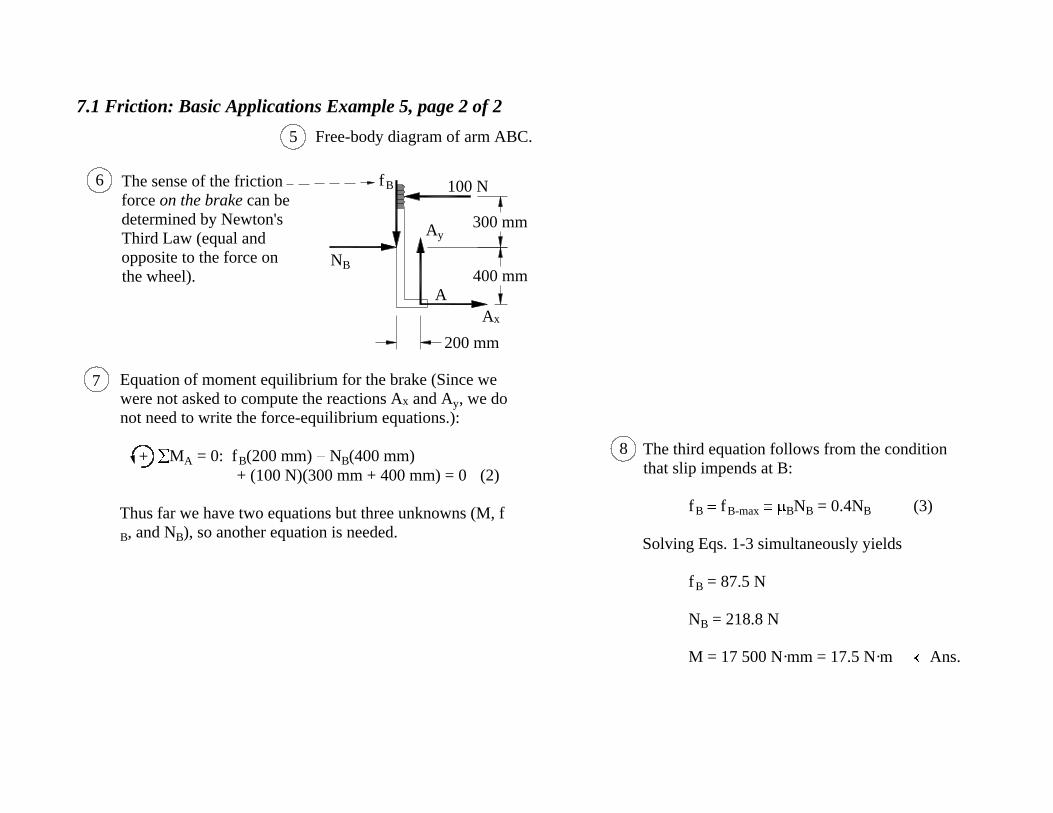
5 Free-body diagram of arm ABC.
f B
N B
200 mm
400 mm
300 mm
100 N
7
+
Equation of moment equilibrium for the brake (Since we
were not asked to compute the reactions A x and A
y, we do
not need to write the force-equilibrium equations.):
M A = 0: f
B(200 mm) N B(400 mm)
+ (100 N)(300 mm + 400 mm) = 0 (2)
Thus far we have two equations but three unknowns (M, f B, and N
B), so another equation is needed.
8
6 The sense of the friction
force on the brake can be
determined by Newton's
Third Law (equal and
opposite to the force on
the wheel).

7.1 Friction: Basic Applications Example 6, page 1 of 4
6. The uniform block is initially at rest when a 10-lb
force is applied. The coefficient of static friction
between the block and the plane is = 0.6.
Determine if the block will move.
1 ft
2 ft
10 lb
20 lb
A
(weight)
7.1 Friction: Basic Applications Example 6, page 2 of 4
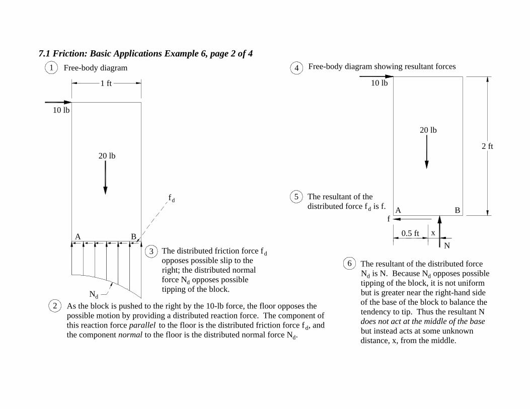
The resultant of the
distributed force fd is f.
5
The distributed friction force fd
opposes possible slip to the
right; the distributed normal
force Nd opposes possible
tipping of the block.
As the block is pushed to the right by the 10-lb force, the floor opposes the
possible motion by providing a distributed reaction force. The component of
this reaction force parallel to the floor is the distributed friction force fd, and
the component normal to the floor is the distributed normal force Nd.
3
2
The resultant of the distributed force
Nd is N. Because Nd opposes possible
tipping of the block, it is not uniform
but is greater near the right-hand side
of the base of the block to balance the
tendency to tip. Thus the resultant N
does not act at the middle of the base
but instead acts at some unknown
distance, x, from the middle.
6
B
Nd
fd
1 Free-body diagram
A
20 lb
10 lb
1 ft
0.5 ft
B
N
f
4 Free-body diagram showing resultant forces
2 ft
A
20 lb
10 lb
x

7.1 Friction: Basic Applications Example 6, page 3 of 4
Equations of equilibrium:
F x = 0: 10 lb f = 0
F y = 0: N 20 lb = 0
M A = 0: (20 lb)(0.5 ft) (10 lb)(2 ft) + N(0.5 ft + x) = 0
Solving these equations gives
f = 10 lb
N = 20 lb
x = 1 ft These are the values required if the system is to
stay in equilibrium, that is, not move. To
determine if the system can produce the 10-lb
friction force f required to keep the system in
equilibrium, we have to compare f with the
maximum possible value of the friction force:
f max N = (0.6)(20 lb) = 12 lb
Because f = 10 lb is less than the 12 lb maximum
possible force, the surfaces can develop enough
force to balance forces in the x direction (thus the
block will not slide to the right).
+
+
7
8
9
+

7.1 Friction: Basic Applications Example 6, page 4 of 4
We next consider whether or not the block will tip.
Recall that solving the equilibrium equations gave the result
x = 1 ft. That is, to maintain equilibrium, the normal force
N must act at the location shown, 0.5 ft to the right of the
block. But this is impossible because N is the normal force
from the ground acting up on the block; the farthest N can
act is at the right hand corner, B. Thus the block will tip
because N cannot act far enough to the right to prevent it.
N (impossible location
because outside the base of
the block)0.5 ft 0.5 ft
x = 1 ft
20 lb
10
f
A B
10 lb

7.1 Friction: Basic Applications Example 7, page 1 of 6
7. The uniform block is initially at rest when the force P
is applied. The coefficient of static friction between the
block and the plane is = 0.6. Determine the minimum
value of P that will cause the block to move.
2 ft
A
1 ft
(weight)20 lb
B
P

7.1 Friction: Basic Applications Example 7, page 2 of 6
P1 ft
20 lb
A
Free-body diagram1
fd
N d
P
20 lb
A
2 ft
Free-body diagram showing resultant forces3
The resultant of the
distributed force fd is f.
f
4
As the block is pushed to the right by the force P, the floor opposes the
possible motion by providing a distributed reaction force. The component
of this reaction force parallel to the floor is the distributed friction force, fd,
and the component normal to the floor is the distributed normal force Nd.
2
The resultant of the distributed force Nd
is N. Because Nd opposes possible
tipping of the block, it is not uniform
but is greater near the right-hand side of
the base of the block to balance the
tendency to tip. Thus the resultant N
does not act at the middle of the base
but instead acts at some unknown
distance, x, from the middle.
5
N
B
B
0.5 ft x

7.1 Friction: Basic Applications Example 7, page 3 of 6
1 ft
A B
20 lb
(weight)
P
Equations of equilibrium:
F x = 0: P f = 0 (1)
F y = 0: N 20 lb = 0 (2)
M A = 0: (20 lb)(0.5 ft) P(2 ft)
+ N(0.5 ft + x) = 0 (3)
Three equations but four unknowns (P, f, N and x),
so one more equation is needed.
The fourth equation comes from considering
possible impending motion. There are two cases to
consider: sliding and tipping.
Case 1: Sliding
6
7
8
9+
++

7.1 Friction: Basic Applications Example 7, page 4 of 6
P
20 lb
(weight)
BA
We have to analyze each case separately. Let's (arbitrarily)
choose Case 1 first. If sliding impends, then
f = f max N = 0.6N (4)
Solving Eqs. 1-4 simultaneously gives
P = 12 lb
N = 20 lb
f = 12 lb
x = 1.2 ft
Case 2: Tipping10 11
12

7.1 Friction: Basic Applications Example 7, page 5 of 6
B
20 lb
P = 12 lb
A
0.5 ft
x = 1.2 ft
N = 20 lbf = 12 lb
But this diagram shows that the only way the equilibrium
equations for Case 1 can be satisfied is if the normal force N
lies to the right of the block (x = 1.2 ft). Since this is
impossible, the Case 1 assumption that sliding impends must
be incorrect.
Free body diagram for Case 1 (Sliding impends)13
14

7.1 Friction: Basic Applications Example 7, page 6 of 6
f x
A
P
20 lb
B
Since the block is just about to tip, it loses contact with the
floor except at the corner B, where the normal force N is
concentrated. Since N acts at the corner, we know
x = 0.5 ft (5)
Solving the equilibrium equations, Eqs. 1, 2, and 3,
simultaneously with Eq. 5 gives
f = 5 lb
N = 20 lb
P = 5 lb Ans.
Since there were only two possibilities, sliding and tipping, and
we eliminated sliding, we know that the above result P = 5 lb is
correct. However, we can also check our work by verifying
that the friction force f is less than the maximum possible
value:
f = 5 lb < f max N = (0.6)(20 lb) = 12 lb. (OK)
Free body diagram for Case 2 (Tipping impends)15
160.5 ft 0.5 ft
N

7.1 Friction: Basic Applications Example 8, page 1 of 3
8. The cylinder is initially at rest when a horizontal
force P is applied. The coefficients of static friction
at A and B are A = 0.3 and
B = 0.6. Determine
the minimum value of P that will cause the cylinder
to move.
0.3 m
P
20 kg
A
B
Radius = 0.2 m
A
0.3 m
P
B
f A
N A
f B
N B
Weight = mg
= (20 kg)(9.81 m/s2 )
= 196.2 N
Free-body diagram
Possible motion of
point B on cylinder.
Force P tends to
rotate the cylinder
clockwise.
The friction force from
the wall opposes the
motion of point B on
the cylinder.
Possible motion of point A.
The friction force from the floor
opposes the motion of point A on
the cylinder.
1
2
3
4
5
0.2 m

7.1 Friction: Basic Applications Example 8, page 2 of 3 +
6
Case 2Case 1
The cylinder rolls up the
wall without slipping.
The cylinder spins
about its center.
B
A
B
A
7 We have to analyze each case separately. Let's
(arbitrarily) choose Case 1 first. Thus if the cylinder
is about to slip about its center, then slip impends
simultaneously at points A and B, so
f A = f
A-max AN
A = 0.3N A (4)
f B = f
B-max BN
B = 0.6N B (5)
Solving Eqs. 1-5 simultaneously gives
P = 554 N
f A = 34.6 N
f B = 312 N
N A = 115 N
N B = 519 N
A negative normal force, N A, is impossible (The
floor can't pull down on the cylinder), so the
assumption of slip at both A and B must be wrong.
Equilibrium equations
F x = 0: P + f
A N B = 0 (1)
F y = 0: 196.2 N + f
B + N A = 0 (2)
M A = 0: f
B(0.2 m) + NB(0.2 m) P(0.3 m) = 0 (3)
There are three equations and five unknowns (P, f A, N
A, f B, N
B),
so two more equations are needed. The two additional equations
come from considering possible impending motion. There are
two cases to consider:
+
+
7.1 Friction: Basic Applications Example 8, page 3 of 3
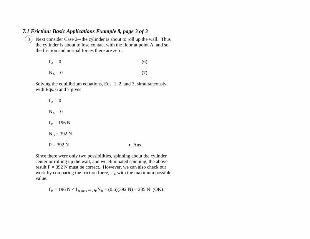
Next consider Case 2 the cylinder is about to roll up the wall. Thus
the cylinder is about to lose contact with the floor at point A, and so
the friction and normal forces there are zero:
f A = 0 (6)
N A = 0 (7)
Solving the equilibrium equations, Eqs. 1, 2, and 3, simultaneously
with Eqs. 6 and 7 gives
f A = 0
N A = 0
f B = 196 N
N B = 392 N
P = 392 N Ans.
Since there were only two possibilities, spinning about the cylinder
center or rolling up the wall, and we eliminated spinning, the above
result P = 392 N must be correct. However, we can also check our
work by comparing the friction force, f B, with the maximum possible
value:
f B = 196 N < f
B-max BN
B = (0.6)(392 N) = 235 N (OK)
8
7.1 Friction: Basic Applications Example 9, page 1 of 4
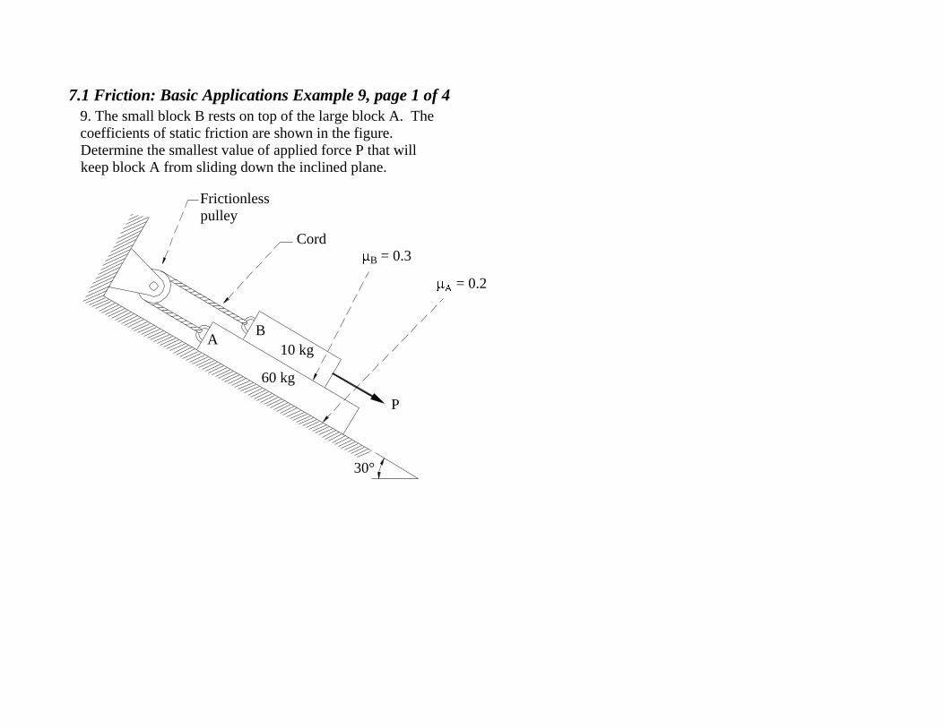
9. The small block B rests on top of the large block A. The
coefficients of static friction are shown in the figure.
Determine the smallest value of applied force P that will
keep block A from sliding down the inclined plane.
AB
60 kg
10 kg
P
Cord
Frictionless
pulley
B = 0.3
= 0.2
30°
7.1 Friction: Basic Applications Example 9, page 2 of 4
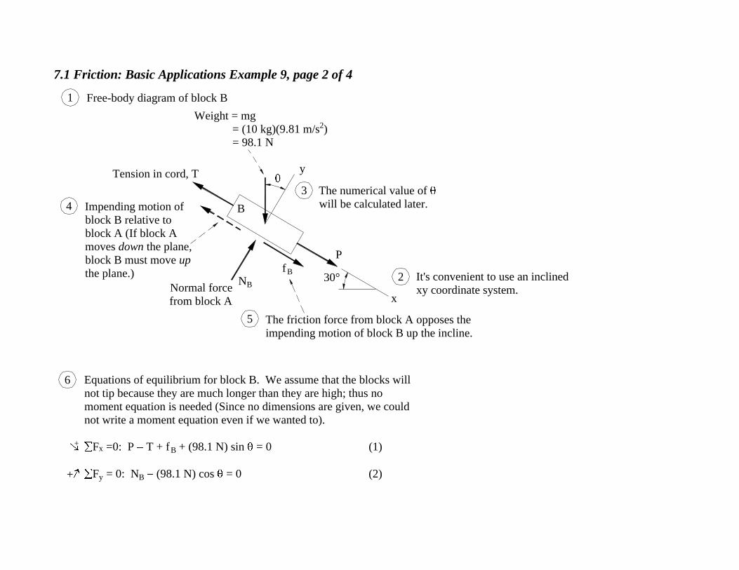
Free-body diagram of block B
Tension in cord, T
Impending motion of
block B relative to
block A (If block A
moves down the plane,
block B must move up
the plane.)
Normal force
from block A
The friction force from block A opposes the
impending motion of block B up the incline.
The numerical value of
will be calculated later.
It's convenient to use an inclined
xy coordinate system.
P
B
30°
x
y
NB
fB
1
4
3
5
2
Weight = mg
= (10 kg)(9.81 m/s2)
= 98.1 N
+
+
Equations of equilibrium for block B. We assume that the blocks will
not tip because they are much longer than they are high; thus no
moment equation is needed (Since no dimensions are given, we could
not write a moment equation even if we wanted to).
F x =0: P T + f
B + (98.1 N) sin = 0 (1)
F y = 0: N
B (98.1 N) cos = 0 (2)
6

7.1 Friction: Basic Applications Example 9, page 3 of 4
60°
30°
= 90° 60° = 30°
x
y
Geometry7
30°
NB
11
9
13
12
10
8
NA
fBT
y
x
= 30°
A
fA
Weight = mg
= (60 kg)(9.81 m/s2 )
= 588.6 N
[Weight of block A alone (Note
that the weight of block B is not
included because block B is not
part of this free-body. The effect
of the weight of block B is
transmitted through the normal
force, N B.)]
Impending motion
of block A relative
to block B.
Impending motion of block A
relative to inclined plane.
Normal force from
inclined plane
Friction force from
inclined plane opposes
motion of block A.
Friction force from block B opposes
motion of block A.
Free-body diagram of block A
30°

7.1 Friction: Basic Applications Example 9, page 4 of 4
14 Equilibrium equations for block A
F x =0: (588.6 N) sin 30° fA f
B T = 0 (3)
F y = 0: (588.6 N) cos 30° + N
A N B = 0 (4)
Four equations in six unknowns (T, P, f A, N
A, f B, N
B). Two
more equations come from the condition of impending sliding
between the blocks and between block A and the plane:
f A f
A-max ANA = 0.2NA (5)
f B f
B-max BN
B = 0.3N B (6)
Solving Eqs. 1-6 simultaneously gives
f A = 119 N
N A = 595 N
f B = 25 N
N B = 85 N
T = 150 N
P = 75 N Ans.
+
+
Free body diagram of block A repeated
fAA
x
yT
fB
NA
NB
30°
= 30°
588.6 N
7.1 Friction: Basic Applications Example 10, page 1 of 8
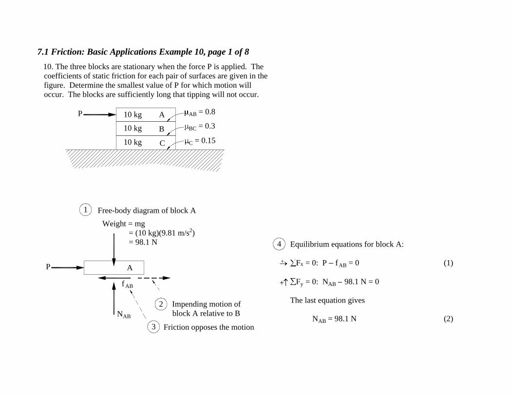
10. The three blocks are stationary when the force P is applied. The
coefficients of static friction for each pair of surfaces are given in the
figure. Determine the smallest value of P for which motion will
occur. The blocks are sufficiently long that tipping will not occur.
Equilibrium equations for block A:
F x = 0: P f
AB = 0 (1)
F y = 0: N
AB 98.1 N = 0
The last equation gives
N AB = 98.1 N (2)
+
+
4
C
A
B
10 kg
10 kg
10 kg
AB = 0.8
BC = 0.3
C = 0.15
P
P A
N AB
f AB
Weight = mg
= (10 kg)(9.81 m/s2 )
= 98.1 N
Impending motion of
block A relative to B
Friction opposes the motion
2
3
Free-body diagram of block A1

7.1 Friction: Basic Applications Example 10, page 2 of 8
Equilibrium equations for block B:
F x = 0: f
AB f BC = 0 (3)
F y = 0: 98.1 N 98.1 N + N
BC = 0
The last equation gives
N BC = 196.2 N (4)
+
+
10
B
N AB = 98.1 N
f AB
Impending motion of block B
relative to block A (An observer
on A would see B moving in this
direction.)
Friction force opposes
relative motion
8 9
Free-body diagram of block B5
Weight = 98.1 N
f BC
N BC
6 Impending motion of
block B relative to C
7 Friction force opposes
relative motion
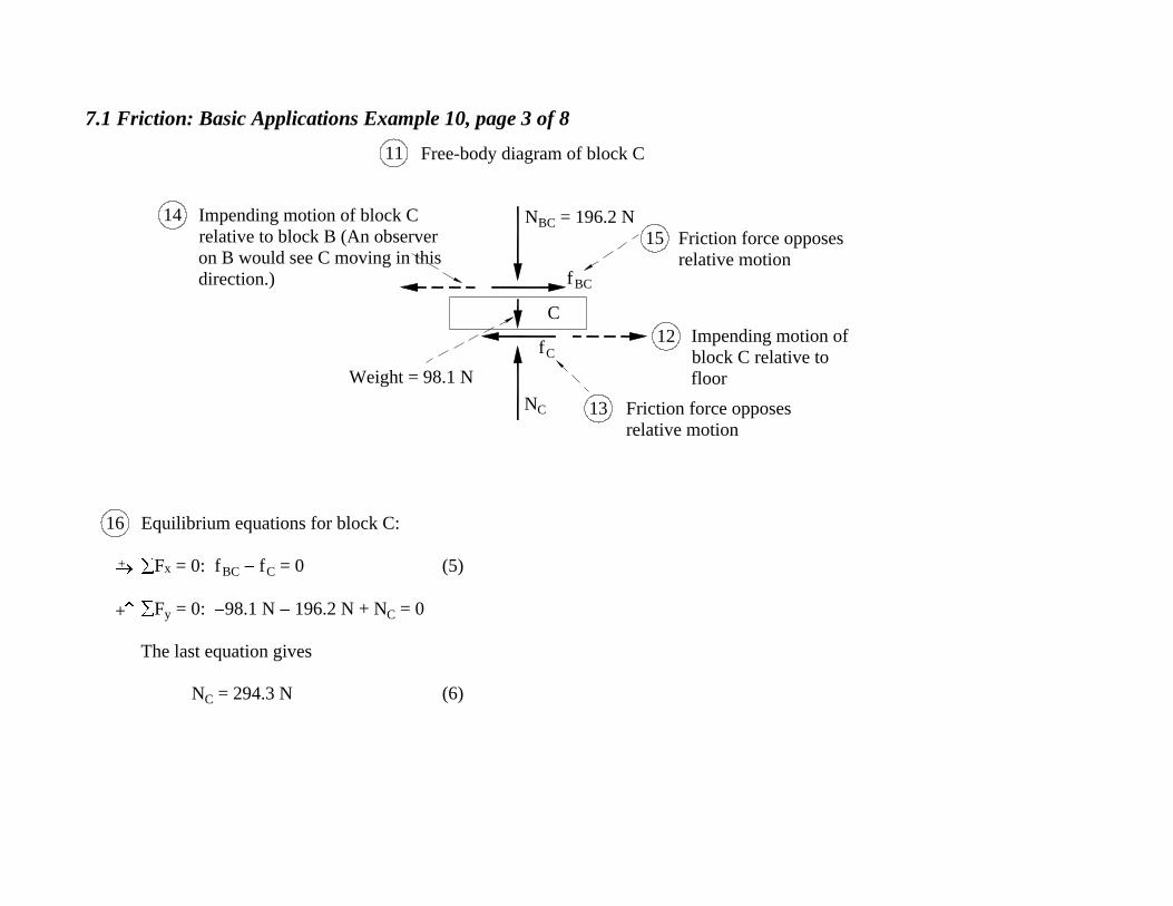
7.1 Friction: Basic Applications Example 10, page 3 of 8
Equilibrium equations for block C:
F x = 0: f
BC f C = 0 (5)
F y = 0: 98.1 N 196.2 N + N
C = 0
The last equation gives
N C = 294.3 N (6)
+
+
16
C
N BC = 196.2 N
f BC
Impending motion of block C
relative to block B (An observer
on B would see C moving in this
direction.)
Friction force opposes
relative motion
14
15
Free-body diagram of block C11
Weight = 98.1 N
f C
N C
12 Impending motion of
block C relative to
floor
13 Friction force opposes
relative motion
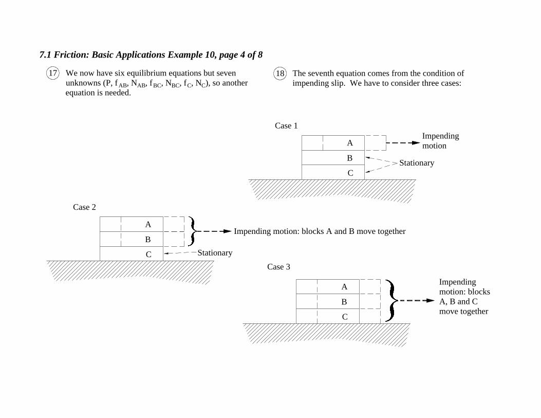
7.1 Friction: Basic Applications Example 10, page 4 of 8
We now have six equilibrium equations but seven
unknowns (P, f AB, N
AB, f BC, N
BC, f C, N
C), so another
equation is needed.
17 The seventh equation comes from the condition of
impending slip. We have to consider three cases:18
A
B
C
Case 1
Impending
motion
Stationary
C Stationary
B
AImpending motion: blocks A and B move together
Case 2
C
B
A
Case 3
Impending
motion: blocks
A, B and C
move together
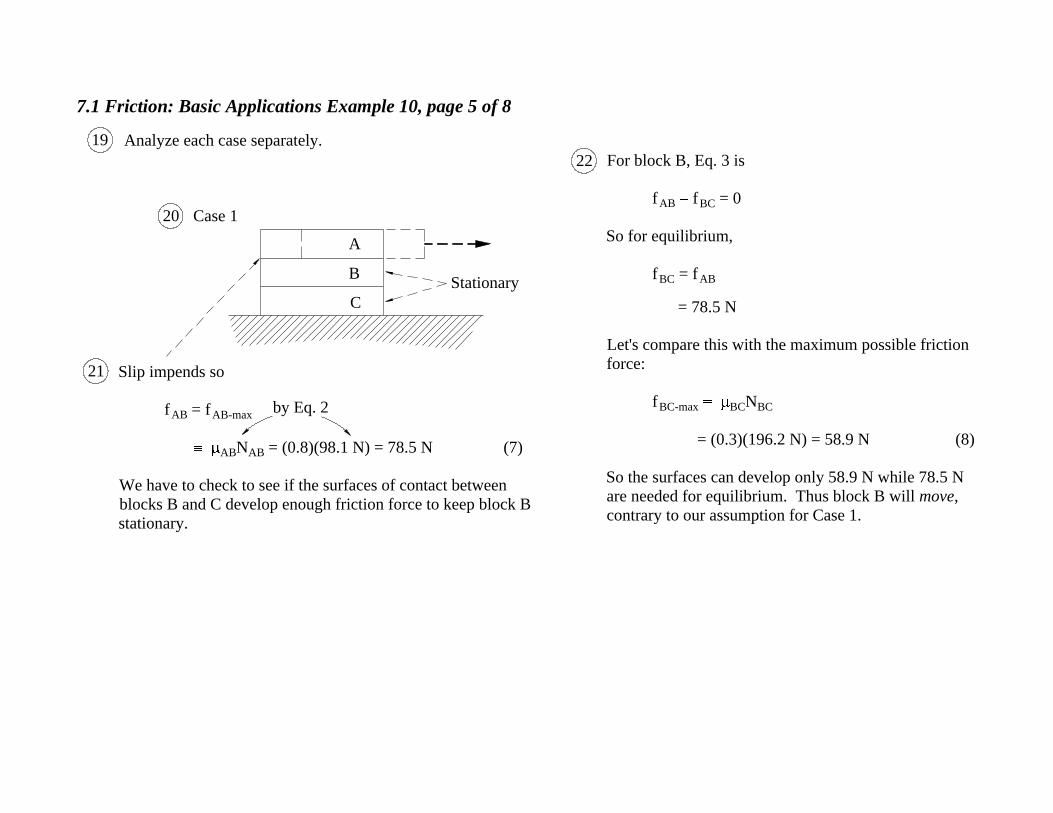
7.1 Friction: Basic Applications Example 10, page 5 of 8
Slip impends so
f AB = f
AB-max
ABN
AB = (0.8)(98.1 N) = 78.5 N (7)
We have to check to see if the surfaces of contact between
blocks B and C develop enough friction force to keep block B
stationary.
20
Analyze each case separately.19
Stationary
C
A
B
Case 1
For block B, Eq. 3 is
f AB f
BC = 0
So for equilibrium,
f BC = f
AB
= 78.5 N
Let's compare this with the maximum possible friction
force:
f BC-max
BCN BC
= (0.3)(196.2 N) = 58.9 N (8)
So the surfaces can develop only 58.9 N while 78.5 N
are needed for equilibrium. Thus block B will move,
contrary to our assumption for Case 1.
by Eq. 2
21
22
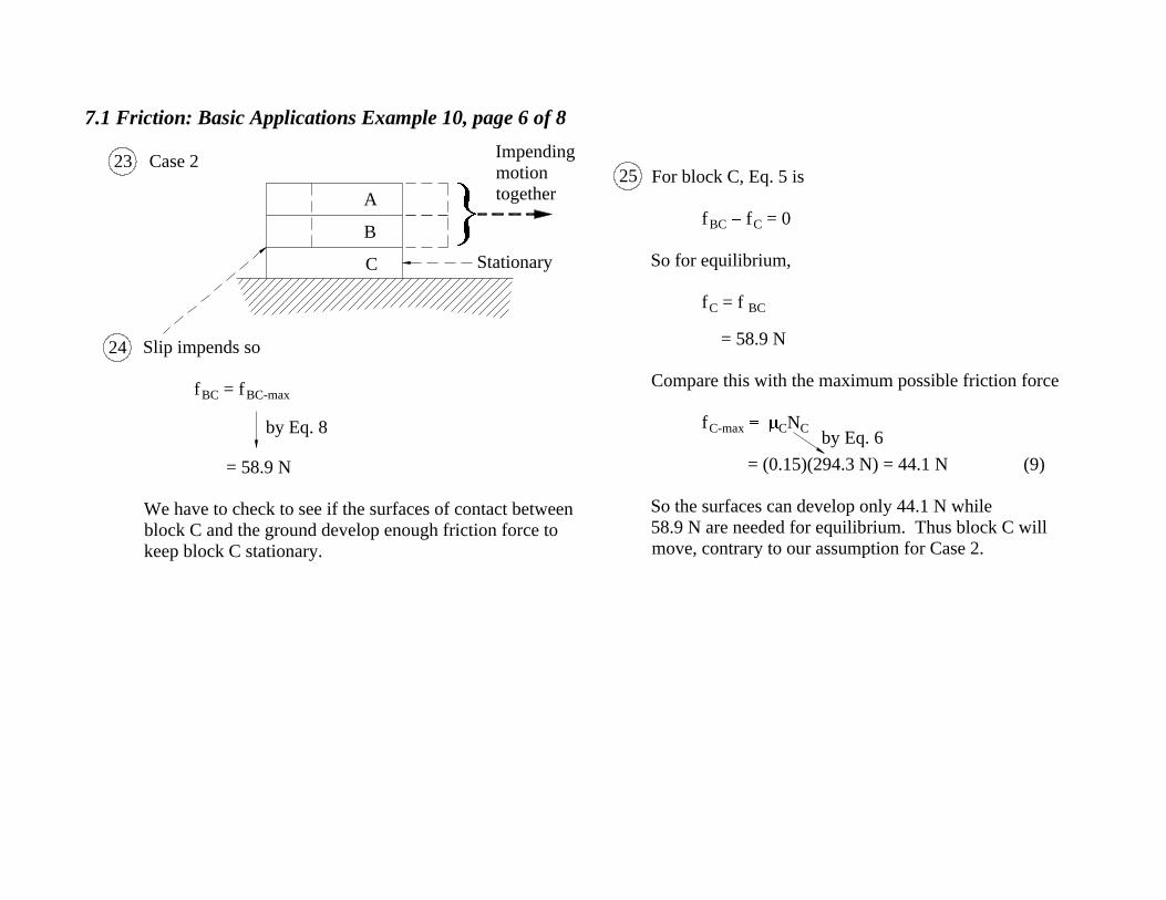
7.1 Friction: Basic Applications Example 10, page 6 of 8
Slip impends so
f BC = f
BC-max
= 58.9 N
We have to check to see if the surfaces of contact between
block C and the ground develop enough friction force to
keep block C stationary.
23For block C, Eq. 5 is
f BC f
C = 0
So for equilibrium,
f C = f
BC
= 58.9 N
Compare this with the maximum possible friction force
f C-max
CN C
= (0.15)(294.3 N) = 44.1 N (9)
So the surfaces can develop only 44.1 N while
58.9 N are needed for equilibrium. Thus block C will
move, contrary to our assumption for Case 2.
Case 2
C
B
A
Stationary
Impending
motion
together
by Eq. 8by Eq. 6
24
25

7.1 Friction: Basic Applications Example 10, page 7 of 8
Slip impends so
f C = f
C-max = 44.1 N (10)
We don't have to check that the surfaces of contact
between blocks A and B and between B and C develop
enough friction to keep A and B in equilibrium, since there
were only three cases of possible motion, and we showed
that the first two cases were impossible. Nonetheless, we
can verify that our work is correct by showing that the
friction forces acting between A and B and between B and
C are less than their maximum possible values.
26 Eq. 5 gives f BC:
f BC f
C = 0
Thus
f BC = f
C
= 44.1 N (11)
and so
by Eq. 8
44.1 N = f BC < f
BC-max = 58.9 N (OK)
Eq. 3 gives f AB:
f AB f
BC = 0
Thus
f AB = f
BC
= 44.1 N (12)
and so
by Eq. 7
44.1 N = f AB < f
AB-max = 78.5 N (OK)
by Eq. 9
Case 3
B
C
AImpending
motion together
by Eq. 10
27
28
7.1 Friction: Basic Applications Example 10, page 8 of 8
A
B
C
Thus the surfaces of contact between blocks A
and B and between B and C can develop
enough friction to keep blocks A, B, and C
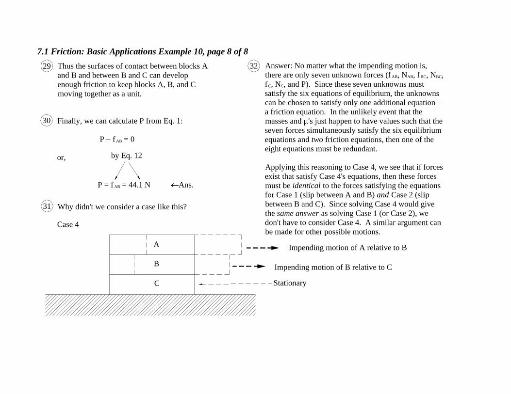
moving together as a unit.
Finally, we can calculate P from Eq. 1:
P f AB = 0
or,
P = f AB = 44.1 N Ans.
Why didn't we consider a case like this?
Impending motion of A relative to B
Impending motion of B relative to C
Answer: No matter what the impending motion is,
there are only seven unknown forces (f AB, N
AB, f
BC, N
BC,
f C, N
C, and P). Since these seven unknowns must
satisfy the six equations of equilibrium, the unknowns
can be chosen to satisfy only one additional equation
a friction equation. In the unlikely event that the
masses and 's just happen to have values such that the
seven forces simultaneously satisfy the six equilibrium
equations and two friction equations, then one of the
eight equations must be redundant.
Applying this reasoning to Case 4, we see that if forces
exist that satisfy Case 4's equations, then these forces
must be identical to the forces satisfying the equations
for Case 1 (slip between A and B) and Case 2 (slip
between B and C). Since solving Case 4 would give
the same answer as solving Case 1 (or Case 2), we
don't have to consider Case 4. A similar argument can
be made for other possible motions. Case 4
Stationary
by Eq. 12
29
30
31
32
7.1 Friction: Basic Applications Example 11, page 1 of 9
25°
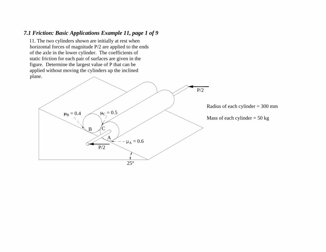
11. The two cylinders shown are initially at rest when
horizontal forces of magnitude P/2 are applied to the ends
of the axle in the lower cylinder. The coefficients of
static friction for each pair of surfaces are given in the
figure. Determine the largest value of P that can be
applied without moving the cylinders up the inclined
plane.
A
B C
B = 0.4
C = 0.5
A = 0.6
P/2
Radius of each cylinder = 300 mm
Mass of each cylinder = 50 kg
P/2

7.1 Friction: Basic Applications Example 11, page 2 of 9
y
x
NC
fC
C
O
fA
NA
25°
A
P
Free-body diagram of lower cylinder
The friction force from
the upper cylinder
opposes the relative
motion of point C on the
lower cylinder.
The friction force from the
plane opposes the motion
of point A on the cylinder.Impending motion of point A on
cylinder. The x component of
the applied force, P cos , is
pushing the cylinder up the
plane.
It is convenient to use an
inclined xy coordinate-system.
Radius = 300 mm
The numerical values of and will be
calculated later.
Weight = mg
= (50 kg)(9.81 m/s2 )
= 490.5 N
Impending motion of point C on lower
cylinder relative to upper cylinder (An
observer on the upper cylinder would
see this motion as the lower cylinder
moves).
1
6
8
7
2
4
3
5

7.1 Friction: Basic Applications Example 11, page 3 of 9
Equilibrium equations for cylinder:
F x = 0: (490.5 N) sin P cos + f
A + N C = 0 (1)
F y = 0: 90.5 N) cos P sin + f
C + N A = 0 (2)
M O = 0: f
A(300 mm) f C(300 mm) = 0 (3)
Geometry
= 90° 65° = 25°
+
+
= 25°
y
x25°
65°
9
10
+
490.5 N
Radius = 300 mm
P
A
NA
fA
O
CfC
NC
x
y
25°
Free-body diagram of lower cylinder repeated

7.1 Friction: Basic Applications Example 11, page 4 of 9
B
NB
fB
fC
C
P
= 25°
O
x
y Weight = 490.5 N
Free-body diagram of upper cylinder
Radius = 300 mm
The friction force
from the plane
opposes the motion
up the plane.Impending motion of point B as
normal force N C pushes the
upper cylinder up the plane.
Impending motion of point C on upper
cylinder relative to lower cylinder (An
observer on the lower cylinder would
see this motion as the upper cylinder
moves).
The friction force from the lower
cylinder opposes the relative
motion of point C on the upper
cylinder..
11
15
14
12
13
NC
7.1 Friction: Basic Applications Example 11, page 5 of 9
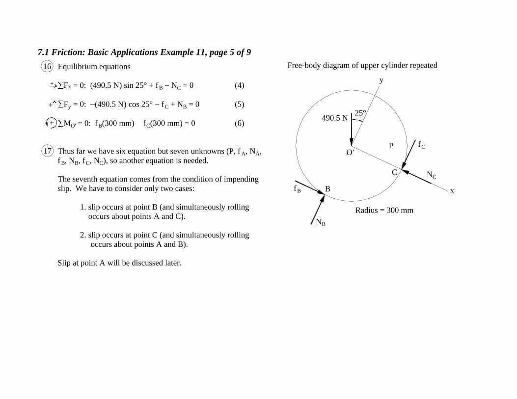
Equilibrium equations
F x = 0: (490.5 N) sin 25° + f
B N C = 0 (4)
F y = 0: (490.5 N) cos 25° f
C + N B = 0 (5)
M O' = 0: f
B(300 mm) f C(300 mm) = 0 (6)
Thus far we have six equation but seven unknowns (P, f A, N
A,
f B, N
B, f C, N
C), so another equation is needed.
The seventh equation comes from the condition of impending
slip. We have to consider only two cases:
1. slip occurs at point B (and simultaneously rolling
occurs about points A and C).
2. slip occurs at point C (and simultaneously rolling
occurs about points A and B).
Slip at point A will be discussed later.
+
+
16
17
+
NC
Radius = 300 mm
490.5 N
y
x
O
25°
P
C
fC
fB
NB
B
Free-body diagram of upper cylinder repeated

7.1 Friction: Basic Applications Example 11, page 6 of 9
Case 1
O'
O
A
B C
A
B
CO
O'
Displacement of point O
(Point O moves up the plane)
Before motion
After motion
Rolling without slipping (The radial
line OA on the lower cylinder
rotates through the same angle, , as
the radial line O'C on the upper
cylinder.)
Slip
For impending slip at B,
f B = f
B-max BN
B = 0.4N B (7)
20
19
18
7.1 Friction: Basic Applications Example 11, page 7 of 9
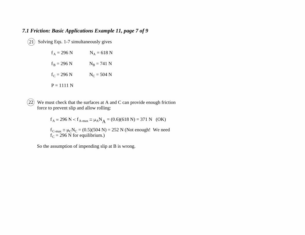
Solving Eqs. 1-7 simultaneously gives
f A = 296 N N
A = 618 N
f B = 296 N N
B = 741 N
f C = 296 N N
C = 504 N
P = 1111 N
We must check that the surfaces at A and C can provide enough friction
force to prevent slip and allow rolling:
f A 296 f
A-max AN
A = (0.6)(618 N) = 371 N (OK)
f C-max
CN C = (0.5)(504 N) = 252 N (Not enough! We need
f C = 296 N for equilibrium.)
So the assumption of impending slip at B is wrong.
21
22

7.1 Friction: Basic Applications Example 11, page 8 of 9
Case 2 (Slip at C, rolling at A
and B)
O'
O
A
B C
A
B
C
O
O'
Displacement
of point O
Before motion
After motion
Rolling without
slipping
Slip
For impending slip at C,
f C = f
C-max CN
C = 0.5N C (8)
2624
23
Rolling without
slipping
25
7.1 Friction: Basic Applications Example 11, page 9 of 9
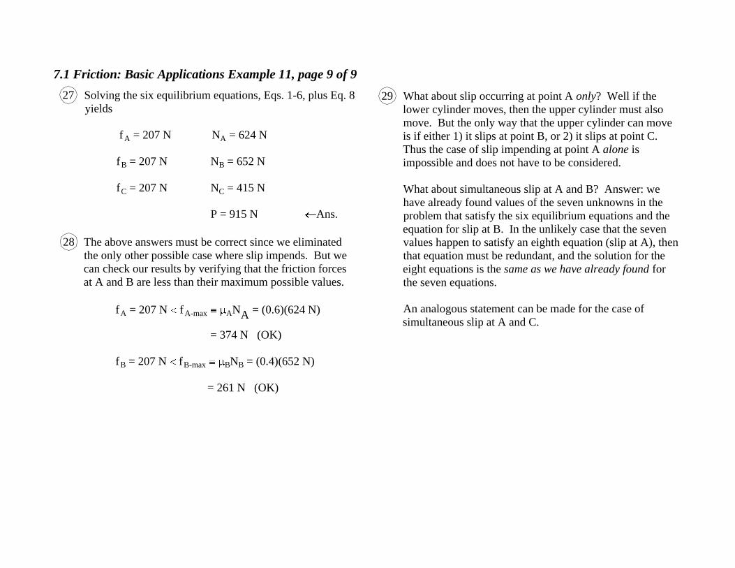
Solving the six equilibrium equations, Eqs. 1-6, plus Eq. 8
yields
f A = 207 N N
A = 624 N
f B = 207 N N
B = 652 N
f C = 207 N N
C = 415 N
P = 915 N Ans.
The above answers must be correct since we eliminated
the only other possible case where slip impends. But we
can check our results by verifying that the friction forces
at A and B are less than their maximum possible values.
f A = 207 N f
A-max AN
A = (0.6)(624 N)
= 374 N (OK)
f B = 207 N f
B-max BN
B = (0.4)(652 N)
= 261 N (OK)
What about slip occurring at point A only? Well if the
lower cylinder moves, then the upper cylinder must also
move. But the only way that the upper cylinder can move
is if either 1) it slips at point B, or 2) it slips at point C.
Thus the case of slip impending at point A alone is
impossible and does not have to be considered.
What about simultaneous slip at A and B? Answer: we
have already found values of the seven unknowns in the
problem that satisfy the six equilibrium equations and the
equation for slip at B. In the unlikely case that the seven
values happen to satisfy an eighth equation (slip at A), then
that equation must be redundant, and the solution for the
eight equations is the same as we have already found for
the seven equations.
An analogous statement can be made for the case of
simultaneous slip at A and C.
27 29
28
