7. water diversion devices
TRANSCRIPT

24 DRAFT IC 4011 (Rev. 04/05/2007)
The use of brush, slash or wood chips mulch over grass seed may be used as long as it ensure that the site is permanently revegetated.
Block the entrance of the closed road using metal structures, large boulders or large tree stumps.
Figure 5. Proper Installation of a Silt Fence.
7. WATER DIVERSION DEVICES Earth Berm Water Bars Earth-berm water bars are narrow, earthen ridges built across roads or trails. They divert water off and away from roads or trails into vegetated areas before it causes erosion. When properly built, they prevent exposed soil from moving, protecting the area until grass vegetation is firmly established. Earth berm water bars are recommended when forest management operations have ceased and the road is closed to further traffic. • Earth Berm Water Bar Installation Guidelines.
Where multiple water bars are required, properly space water bars according to Table 3.
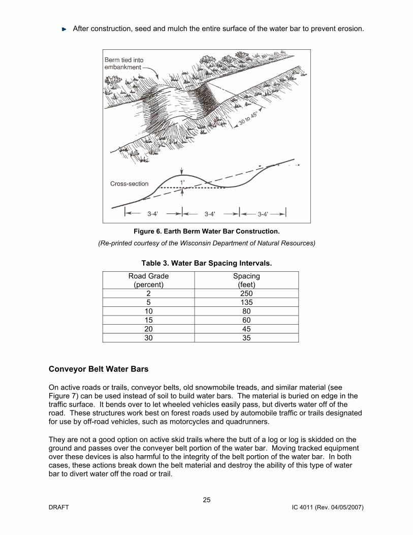
As shown in Figure 6, the water bar should be placed at an angle of 30 to 45 degrees, relative to the road, to allow for runoff to drain from the inlet, through the trench, and into the adjacent forest floor or vegetation.
Dig a trench, 12 to 18 inches below the surface of the road or trail and extend it beyond both sides of the road or trail to prevent runoff from bypassing the water bar.
The uphill end of the water bar should extend beyond the side ditch of the road and into an earthern berm to fully intercept any ditch flows.
The outflow end of the water bar is to be fully open and extended far enough beyond the edge of the road or trail to safely disperse runoff water onto the undisturbed forest floor.
25 DRAFT IC 4011 (Rev. 04/05/2007)
After construction, seed and mulch the entire surface of the water bar to prevent erosion.
Figure 6. Earth Berm Water Bar Construction.
(Re-printed courtesy of the Wisconsin Department of Natural Resources)
Table 3. Water Bar Spacing Intervals.
Road Grade (percent)
Spacing (feet)
2 250 5 135
10 80 15 60 20 45 30 35
Conveyor Belt Water Bars
On active roads or trails, conveyor belts, old snowmobile treads, and similar material (see Figure 7) can be used instead of soil to build water bars. The material is buried on edge in the traffic surface. It bends over to let wheeled vehicles easily pass, but diverts water off of the road. These structures work best on forest roads used by automobile traffic or trails designated for use by off-road vehicles, such as motorcycles and quadrunners.
They are not a good option on active skid trails where the butt of a log or log is skidded on the ground and passes over the conveyer belt portion of the water bar. Moving tracked equipment over these devices is also harmful to the integrity of the belt portion of the water bar. In both cases, these actions break down the belt material and destroy the ability of this type of water bar to divert water off the road or trail.

26 DRAFT IC 4011 (Rev. 04/05/2007)
When Building Conveyor Belt Water Bars Follow These Instructions:
• Dig a trench at a 30- to 45-degree angle to the road or skid trail. The face of the cut should be on the uphill side.
• Place the conveyor belt against the face of the cut. Leave at least 6 inches of belt above the surface of the road. Refill the trench and compact the soil. If necessary, nail a two-by-eight board to the base of the belt to keep it straight and to hold it in the ground.
• Remove berms or other obstructions from the lower end of the water bar to allow water to move off the road. Water should flow into a stable vegetated area, away from open water.
• Space conveyor belt water bars as you would earthen water bars (see Table 3). • Old snowmobile treads and other similar material can be used in place of conveyor belts.
Figure 7. A Conveyor Belt Water Bar.
(Reprinted courtesy of the University of Minnesota Extension Service)
Temporary Water Bars Made from Slash or Logs
Logs or logging debris (slash) consisting of branches, broken tops, and brush can be used to create temporary water bars (See Figure 8). Operators build logging debris water bars across traffic surfaces to divert water into vegetated areas. This reduces erosion and helps maintain the road. Water bars made from logging debris are not as effective as those previously discussed, since water can filter through. Still, they can be used in many applications. They work best in low traffic areas with low slopes (e.g., slopes are less than 5 percent).
Log and slash water bars are best placed where use of more substantial water diversion options is limited; For example, on roads and trails with limited traffic or little slope, or when forest operations are shut down for a short time. They also can be used when the soil is frozen or when shallow, rocky soils, such as those found in parts of the Western Upper Peninsula make it difficult to install earth berm or conveyor belt water bars.
27 DRAFT IC 4011 (Rev. 04/05/2007)
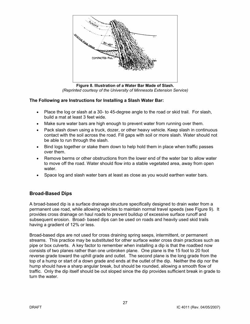
Figure 8. Illustration of a Water Bar Made of Slash. (Reprinted courtesy of the University of Minnesota Extension Service)
The Following are Instructions for Installing a Slash Water Bar:
• Place the log or slash at a 30- to 45-degree angle to the road or skid trail. For slash, build a mat at least 3 feet wide.
• Make sure water bars are high enough to prevent water from running over them. • Pack slash down using a truck, dozer, or other heavy vehicle. Keep slash in continuous
contact with the soil across the road. Fill gaps with soil or more slash. Water should not be able to run through the slash.
• Bind logs together or stake them down to help hold them in place when traffic passes over them.
• Remove berms or other obstructions from the lower end of the water bar to allow water to move off the road. Water should flow into a stable vegetated area, away from open water.
• Space log and slash water bars at least as close as you would earthen water bars. Broad-Based Dips A broad-based dip is a surface drainage structure specifically designed to drain water from a permanent use road, while allowing vehicles to maintain normal travel speeds (see Figure 9). It provides cross drainage on haul roads to prevent buildup of excessive surface runoff and subsequent erosion. Broad- based dips can be used on roads and heavily used skid trails having a gradient of 12% or less. Broad-based dips are not used for cross draining spring seeps, intermittent, or permanent streams. This practice may be substituted for other surface water cross drain practices such as pipe or box culverts. A key factor to remember when installing a dip is that the roadbed now consists of two planes rather than one unbroken plane. One plane is the 15 foot to 20 foot reverse grade toward the uphill grade and outlet. The second plane is the long grade from the top of a hump or start of a down grade and ends at the outlet of the dip. Neither the dip nor the hump should have a sharp angular break, but should be rounded, allowing a smooth flow of traffic. Only the dip itself should be out sloped since the dip provides sufficient break in grade to turn the water.

28 DRAFT IC 4011 (Rev. 04/05/2007)
Figure 9. Broad-based Dip.
(Figure courtesy of the Wisconsin Department of Natural Resources)
• Specifications for Broad-Based Dip Installation:
Installation takes place following basic roadbed construction.
A 20 foot long, 3% reverse grade is constructed into the existing roadbed by cutting from upgrade of the dip location and using cut material to build up the mound for the reverse grade.
Space broad-based dips as shown in Table 4.
As shown in Figure 9, depending the soils and amount of and type of traffic, the dip and reverse grade section will often require applying a layer of approximately 20 tons of 3-inch crushed stone to avoid rutting or breaking down of the dips and reverse grade section. Another option is to apply geotextile fabric along the length of the dip and reverse grade sections, and apply coarse aggregate or gravel at a minimum depth of 3 inches (6 inches depth is optimal).
29 DRAFT IC 4011 (Rev. 04/05/2007)
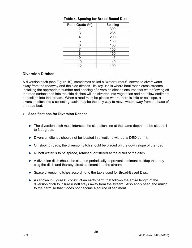
Table 4. Spacing for Broad-Based Dips. Road Grade (%) Spacing
2 300 3 235 4 200 5 180 6 165 7 155 8 150 9 145
10 140 12 100
Diversion Ditches A diversion ditch (see Figure 10), sometimes called a "water turnout", serves to divert water away from the roadway and the side ditches. Its key use is where haul roads cross streams. Installing the appropriate number and spacing of diversion ditches ensures that water flowing off the road surface and into the side ditches will be diverted into vegetation and not allow sediment deposition into the stream. When a road must be placed where there is little or no slope, a diversion ditch into a collecting basin may be the only way to move water away from the base of the road bed. • Specifications for Diversion Ditches:
The diversion ditch must intersect the side ditch line at the same depth and be sloped 1 to 3 degrees.
Diversion ditches should not be located in a wetland without a DEQ permit.
On sloping roads, the diversion ditch should be placed on the down slope of the road.
Runoff water is to be spread, retained, or filtered at the outlet of the ditch.
A diversion ditch should be cleaned periodically to prevent sediment buildup that may clog the ditch and thereby direct sediment into the stream.
Space diversion ditches according to the table used for Broad-Based Dips.
As shown in Figure 8, construct an earth berm that follows the entire length of the diversion ditch to insure runoff stays away from the stream. Also apply seed and mulch to the berm so that it does not become a source of sediment.

30 DRAFT IC 4011 (Rev. 04/05/2007)
Figure 10. Diversion Ditch.
(Re-printed courtesy of the Wisconsin Department of Natural Resources) Cross Drainage Culverts The primary purpose of cross drainage culverts is to drain water from a ditch on one side of a road to the other side of the road and into grassy vegetation or energy dissipaters. • BMP Specifications for Installing a Cross Drainage Culvert (see Figure 11):
Culvert length should be long enough so both ends extend 1 foot beyond side slope (this is in contrast to culverts used for stream crossings which require that the culvert ends extend a minimum of 2 feet beyond the side slope).
Culverts should be installed with a 2% slope to reduce the possibility of clogging with leaf litter or other debris.
Align the culvert by placing it on a downgrade angle in which the diameter of the culvert is equal to cross sectional area of the side ditch.
Install erosion control materials for both the inflows and outflows of culverts to minimize undercutting at the culvert inlet or erosion occurring down slope of the outlet; this protection can be in the form of geotextile fabric overlain by rock large enough not to wash away or move during a significant rain event (ranging from 3-12 inches in diameter).
Select the size of culvert according to the size of the road and the general amount of surface area that is being drained by the ditch. The cross-drainage diameter of a culvert should be a minimum of 18 inches.

31 DRAFT IC 4011 (Rev. 04/05/2007)
Figure 11. Cross-Drainage Culvert.
(Re-printed courtesy of Wisconsin DNR)
8. STREAM CROSSINGS As described in “Section 2 Laws and Permits”, installing a new or upgrading an existing stream crossing requires a permit from DEQ prior to installation. This is through the DEQ/US Army Corps of Engineers (USACE) joint permit application process. It is best to work with local DEQ staff when developing plans for stream crossings from the outset. This will result in less time and effort for the landowner or their designated agent during the permit application and review process. Information regarding this application is available at www.michigan.gov/jointpermit. Permit requirements apply to intermittent streams (flows only occur during certain times of the year, particularly spring during snowmelt), as well as permanently flowing streams. A stream, permanent or intermittent, is an area with a defined streambed and bank and visible evidence of a continued flow or continued occurrence of water. While dry for much of the year, intermittent streams are important during frequent rains in the spring. Because of these frequent rain events, intermittent streams provide essential habitat for trout and other fish during spawning runs. Therefore, protect them as carefully as you would a permanent flowing stream. It is against DEQ regulations to transport felled logs or heavy machinery through even the smallest, shallowest dry streambed. Instead, there are two placement techniques for stream