7-cell main canopies - flight concepts...
TRANSCRIPT

4357 D PARK DRIVE
NORCROSS, GA 30093 USA Phone (770)-279-7733 FAX (770)-279-7729
MAIN CANOPY OWNER'S MANUAL
and
PACKING INSTRUCTIONS
for all
7-Cell MAIN CANOPIES
May 2004

FLIGHT CONCEPTS INTERNATIONAL, INCORPORATED
7-CELL OWNER’S MANUAL May 2004 PAGE 2
1. TRAINING AND/OR EXPERIENCE ARE REQUIRED TO LOWER THE RISK OF SERIOUS INJURY OR DEATH.
NEVER USE THIS EQUIPMENT UNLESS YOU HAVE:
A. READ THIS WARNING LABEL AND COMPLETED A "CONTROLLED PROGRAM OF INSTRUCTION" IN THE USE OF THIS PARACHUTE ASSEMBLY.
--OR- B. READ THIS WARNING LABEL AND ALL APPROPRIATE OWNER/FLIGHT MANUALS, PACKING INSTRUCTIONS AND COMPLETED AT LEAST 100 RAM AIR PARACHUTE JUMPS.
2. LOWER THE RISK OF DEATH, SERIOUS INJURY, CANOPY DAMAGE AND HARD OPENINGS BY NEVER EXCEEDING THE LIMITS SHOWN BELOW:
MAXIMUM DEPLOYMENT SPEED 130 KNOTS
MAXIMUM GROSS WEIGHT (JUMPER + CLOTHING + EQUIPMENT) POUNDS
MODEL :
SERIAL NUMBER :
DATE OF MANUFACTURE :
!!! THE USER ASSUMES ALL RISK !!!
PARACHUTE SYSTEMS SOMETIMES FAIL CAUSING DEATH OR SERIOUS INJURY REGARDLESS OF HOW IT IS MAINTAINED, PACKED, DEPLOYED OR OPERATED.
FLIGHT CONCEPTS INTERNATIONAL 4357 D PARK DRIVE
NORCROSS, GA 30093 USA Phone (770)-279-7733 FAX (770)-279-7729
REMOVAL OF THIS LABEL VOIDS ANY AND OR ALL CUSTOMER SERVICE PROGRAMS

FLIGHT CONCEPTS INTERNATIONAL, INCORPORATED
7-CELL OWNER’S MANUAL May 2004 PAGE 3
TABLE OF CONTENTS
Title Page 1 Data/Warning Panel 2 Contents 3 About this Manual 3 Policy Statement 3 Parts List 4 Revision List 4 Inspection Instructions 5 Canopy Specifications 8 Trim Specifications 10 Packing Instructions 13 Packing Instructions For Diaper 19 WARNING For Diaper Users 27 Operating Instructions and Limitations 28 Canopy Care and Maintenance 31 Warning - Disclaimer 32
ABOUT THIS MANUAL
Please read this manual thoroughly before assembling, packing, and using your Flight Concepts International, Inc. main canopy. This manual will provide you with important information that will help you better use this product.
POLICY STATEMENT
Flight Concepts International, Inc. may change any of the announcements, information, policies, rules, or procedures set forth in this manual. This manual is updated as revisions occur and may not always reflect new or modified procedures and information. Statements in this manual may not be regarded in the nature of binding obligations on the manufacturer or the seller.

FLIGHT CONCEPTS INTERNATIONAL, INCORPORATED
7-CELL OWNER’S MANUAL May 2004 PAGE 4
PARTS LIST FOR A FLIGHT CONCEPTS MAIN CANOPY
Each Flight Concepts, Inc. Main Canopy includes the following components: * One (1) Canopy with suspension and control lines. * One (1) Slider. * Four (4) connector links (as ordered). * One (1) Flight Concepts, Inc. Main Owner's Manual.
REVISION LIST
First Edition: March 1994
Second Edition: March 1999
Third Edition: January 2001
Fourth Edition: May 2004
This owner's manual and/or the packing instructions may be revised from time to time by Flight Concepts, Inc. without notice. Product owners should contact Flight Concepts, Inc. periodically to insure the currency of this publication.
It is the intention of Flight Concepts, Inc. to aid in the education of skydivers and the general public about safe parachuting practices. Therefore, this manual may be reproduced in whole, or in part by anyone wishing to do so.
Flight Concepts, Inc. welcomes all comments about this manual, as they will help us to make future editions more complete and easier to use. Please put your suggestions in writing and send them to:
Flight Concepts International, Inc. 4357-D Park Drive
Norcross, Ga. 30093 USA

FLIGHT CONCEPTS INTERNATIONAL, INCORPORATED
7-CELL OWNER’S MANUAL May 2004 PAGE 5
INSPECTION INSTRUCTIONS NOTE: THE INSPECTION OF A FLIGHT CONCEPTS INTERNATIONAL, INC. MAIN CANOPY PRIOR TO BEING ASSEMBLED INTO A PARACHUTE HARNESS/CONTAINER SYSTEM, OR CAN ONLY BE DONE BY THE MANUFACTURER OR AN FAA CERTIFIED SENIOR OR MASTER PARACHUTE RIGGER. ADDITIONALLY, TO INSURE THE CORRECTNESS OF THE INSPECTION PROCEDURE, THESE INSPECTION INSTRUCTIONS MUST BE FOLLOWED EXACTLY.
STEP 1.) Insure that all of the correct parts were received by checking the parts list.
STEP 2.) Prior to assembly, visually inspect each topskin and bottom skin panel for any defects, rips, stains, or any other damage to the canopy or its seams. If the canopy is being inspected after a deployment, be sure to inspect each panel very carefully for any possible damage that may have occurred during use.
STEP 3.) Visually inspect each rib. Start at the leading edge and move to the trailing edge by looking inside each half cell. Inspect for any sign of defects, rips, stains, or any other damage to canopy or its seams.
STEP 4.) Visually inspect each cascade (finger-trapped line connection) to insure that they have been stitched correctly. Insure that all of the suspension lines are looped tightly onto the attachment point tapes on the bottom skin of the canopy. If a suspension line is not looped tightly, lightly pull the line away from the line attachment loop to tighten the knot around the line attachment point.
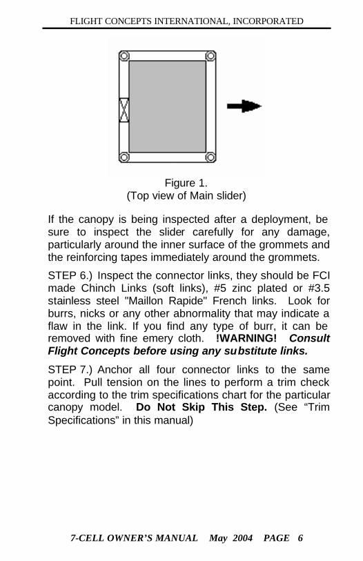
STEP 5.) Inspect the Main slider for correct installation. (See Figure 1.) NOTE: The reinforcement tape should face the canopy and there should not be any type of hole in this slider what so ever.
FLIGHT CONCEPTS INTERNATIONAL, INCORPORATED
7-CELL OWNER’S MANUAL May 2004 PAGE 6
Figure 1.
(Top view of Main slider)
If the canopy is being inspected after a deployment, be sure to inspect the slider carefully for any damage, particularly around the inner surface of the grommets and the reinforcing tapes immediately around the grommets.
STEP 6.) Inspect the connector links, they should be FCI made Chinch Links (soft links), #5 zinc plated or #3.5 stainless steel "Maillon Rapide" French links. Look for burrs, nicks or any other abnormality that may indicate a flaw in the link. If you find any type of burr, it can be removed with fine emery cloth. !WARNING! Consult Flight Concepts before using any substitute links.
STEP 7.) Anchor all four connector links to the same point. Pull tension on the lines to perform a trim check according to the trim specifications chart for the particular canopy model. Do Not Skip This Step. (See “Trim Specifications” in this manual)

FLIGHT CONCEPTS INTERNATIONAL, INCORPORATED
7-CELL OWNER’S MANUAL May 2004 PAGE 7
STEP 8.) Inspect the suspension lines and the control lines for proper continuity. Look for any frayed or damaged areas. If the canopy is being inspected after a deployment, be sure to inspect the lines carefully for any damage, particularly around the connector links. Each line group must be routed to its connector link without any twists, and without passing under, around, or through any other line group.
STEP 9.) Inspect the harness/container system according to the manufacturer’s instructions. Inspect the control line guide rings on the back of the Main rear risers, to insure smoothness, and to look for cracks or burrs.
NOTE: To assure the proper trim when the brakes are set, measure the distance from the fold at the top of the Main rear riser to the control line guide ring. The ring must be attached 4" below the fold and on the back of each rear riser. This is a P.I.A. (Parachute Industry Association) standard. If the ring is attached at a different measurement, the break setting of the Main canopy must be modified to insure correct canopy trim is maintained. (Contact Flight Concepts International, Inc. for additional instructions)
The Main inspection process is now complete, the canopy may be assembled on to a harness/container system if no problems were discovered.

FLIGHT CONCEPTS INTERNATIONAL, INCORPORATED
7-CELL OWNER’S MANUAL May 2004 PAGE 8
CANOPY SPECIFICATIONS
7 Cell Classic Model Size *Maximum Suspended Weight Aspect Ratio Weight Estimated Pack Volume Cricket 145 160 2.0 6.0 Est. 342 Firelite 170 190 2.1 6.3 Est. 366
Maverick 200 220 2.4 6.8 Est. 417 Fury 200 200 220 2.0 7.5 Est. 403
Fury 220 242 2.0 7.7 Est. 423 Sharpchuter 245 269 2.4 7.8 Est. 440
Startrac I 265 291 1.8 9.3 Est. 580 Startrac II 290 319 2.0 11.3 Est. 608 Startrac III 320 352 2.0 11.8 Est. 648
Prodigy Model Size *Maximum Suspended Weight. Aspect Ratio Weight Estimated Pack Volume
Prodigy 150 150 173 2.13 7.0 Est. 407 Prodigy 175 175 201 2.13 7.4 Est. 453 Prodigy 200 200 230 2.13 7.8 Est. 495 Prodigy 225 225 258 2.13 8.6 Est. 532 Prodigy 250 250 286 2.13 9.5 Est. 600

FLIGHT CONCEPTS INTERNATIONAL, INCORPORATED
7-CELL OWNER’S MANUAL May 2004 PAGE 9
CANOPY SPECIFICATIONS (continued)
Express Model Size *Maximum Suspended Weight Aspect Ratio Weight Estimated Pack Volume Express 137 137 150 1.95 5.6 Est. 327 Express 150 150 164 1.95 6.2 Est. 340 Express 167 167 180 1.95 7.0 Est. 352 Express 175 175 200 1.95 7.8 Est. 374 Express 187 187 210 1.95 8.6 Est. 399 Express 200 200 225 1.95 9.5 Est. 425
Manufacturer’s Recommended Maximum Suspended Weight (defined as: Jumper or (Jumpers/Tandem)+ Clothing + Equipment) jumping in near perfect conditions.
The two types of fabric for all models is: F-111 (1.1 oz Nylon Ripstop, 0-3 CFM) or Zero Porosity (1.2 oz Nylon Ripstop, 0 CFM).
The two optional types of line are: 725lb. Microline or 525lb. Dacron

FLIGHT CONCEPTS INTERNATIONAL, INCORPORATED
7-CELL OWNER’S MANUAL May 2004 PAGE 10
TRIM SPECIFICATIONS (in inches) The line specifications in this chart are given under the condition that all four risers are
anchored at the same point, and that the control line guide rings on the rear risers are 4" below the upper fold at the end of the riser.
These dimensions can be verified by laying the canopy on its side (See Figure 1.) and anchoring the measuring instrument at the link. (See Figure 2.)
The dimensions given are from the link to the top of the line loop at the canopy. The dimensions given can vary due the link size and or the attachment method. The maximum tolerance for the trim specifications are +/- 1 inch. The number one is located at the end rib. The measurements on the steering lines are with the brakes set.
Figure 1. Figure 2.

FLIGHT CONCEPTS INTERNATIONAL, INCORPORATED
7-CELL OWNER’S MANUAL May 2004 PAGE 11
7 Cell Classic Model Cricket Firelite Maverick Fury 200 Fury Sharpchuter
Total “A” Line Length 111.6 114.9 134.6 122.5 128.4 132.4 Total “B” Line 114.6 118.9 138.9 126.7 132.9 136.3 Total “C” Line 121.1 125.4 145.1 133.9 140.4 144.6 Total “D” Line 130.6 135.1 154.9 144.4 151.4 154.5
Total To Tail w/Brakes Set 131.5 138.8 139.3 147.3 154.5 159.0
Demonstration Model ZP Manta Startrac I Startrac II Startrac III
Total “A” Line Length 133.3
133.3
140.6 Total “B” Line 136.4
136.4
143.9
Total “C” Line 146.8
146.8
155.3 Total “D” Line 161.0
161.0
169.1
Total To Tail w/Brakes Set
157.3
157.3
165.2

FLIGHT CONCEPTS INTERNATIONAL, INCORPORATED
7-CELL OWNER’S MANUAL May 2004 PAGE 12
Express Model Express 137 150 167 175 187 200
Total “A” Line Length 80.5 84.2 88.8 90.9 93.9 97.1 Total “B” Line 82.7 86.5 91.2 93.4 96.5 99.7 Total “C” Line 89.9 94.0 99.1 101.5 104.9 108.4 Total “D” Line 100.3 104.9 110.6 113.2 117.0 121.0
Total To Tail w/Brakes Set 96.8 101.3 106.9 109.4 113.1 117.0
Prodigy Model Prodigy 150 175 200 225 250
Total “A” Line Length 106.4 114.8 122.7 130.0 137.0 Total “B” Line 109.1 117.8 125.9 133.4 140.6 Total “C” Line 114.3 123.4 131.8 139.7 147.2 Total “D” Line 122.9 132.6 141.7 150.2 158.3
Total To Tail w/Brakes Set
117.2 126.6 135.3 143.5 151.3
FLIGHT CONCEPTS INTERNATIONAL, INCORPORATED
7-CELL OWNER’S MANUAL May 2004 PAGE 13
PRO* PACKING INSTRUCTIONS (PROPER RAM-AIR ORIENTATION)
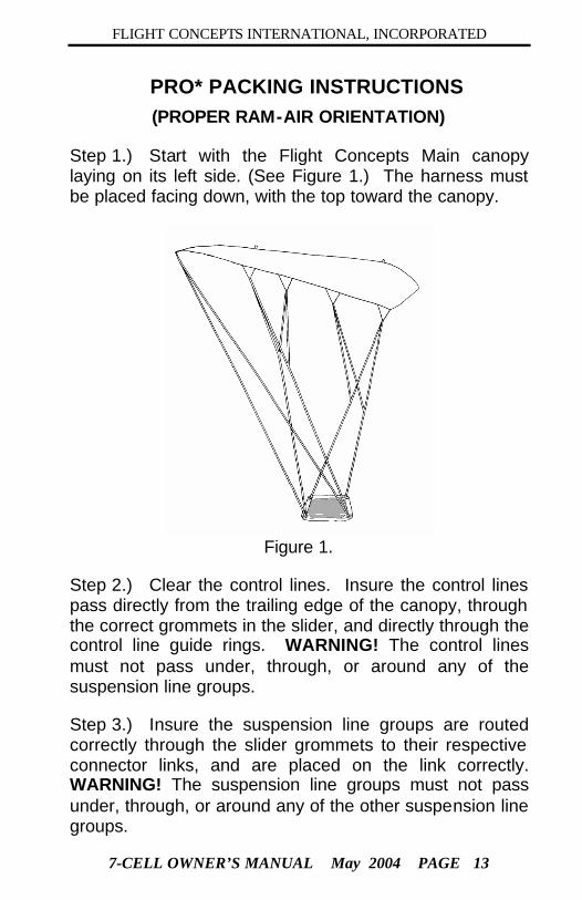
Step 1.) Start with the Flight Concepts Main canopy laying on its left side. (See Figure 1.) The harness must be placed facing down, with the top toward the canopy.
Figure 1.
Step 2.) Clear the control lines. Insure the control lines pass directly from the trailing edge of the canopy, through the correct grommets in the slider, and directly through the control line guide rings. WARNING! The control lines must not pass under, through, or around any of the suspension line groups.
Step 3.) Insure the suspension line groups are routed correctly through the slider grommets to their respective connector links, and are placed on the link correctly. WARNING! The suspension line groups must not pass under, through, or around any of the other suspension line groups.

FLIGHT CONCEPTS INTERNATIONAL, INCORPORATED
7-CELL OWNER’S MANUAL May 2004 PAGE 14
Step 4.) Set the brakes by pulling the control line down through the guide ring until
the brake loop “cat-eye” just passes through the guide
ring. (See Figure 2.)
Figure 2
Step 5.) Insert the stiffened upper portion of the control toggle through the loop and pull the control line back up tightly against the ring guide. (See Figure 3.) "S" fold the remaining break line next to the control toggle and stow it in the Velcro loop provided. Mate the Velcro on the control toggle with the Velcro on the rear riser. Insure both deployment brakes are set before continuing the pack-job.
Figure 3

FLIGHT CONCEPTS INTERNATIONAL, INCORPORATED
7-CELL OWNER’S MANUAL May 2004 PAGE 15
Step 6.) With the harness / container system secured, apply tension to the lines, and step between the right and left line groups and grasp the right line groups in the right hand and the left line groups in the left hand. Push the slider toward the canopy, and walk forward. Pick up the canopy by the suspension lines and allow it to hang downward (See Figure 4.) Push the slider up as far as it will go until each slider grommet comes to its respective slider stop.
Figure 4
Step 7.) Step out from between the line groups and hold them in one hand. Clear the bottom seams of each cell with the “knife edge” of the hand. (See Figure 5.) This must be done between the “A", “B”, “C", and "D" line groups. Clear the four seams of each cell to the left and right. After all the seams are cleared on each side of the canopy, clear the trailing edge between the control lines.
Figure 5

FLIGHT CONCEPTS INTERNATIONAL, INCORPORATED
7-CELL OWNER’S MANUAL May 2004 PAGE 16
NOTE: Figure 6. is a graphic representation of what the canopy folds should look like when Step 7) is done correctly. The bottom surface of the canopy and the control lines will be symmetric. Clear all nine cells at the nose and insure the canopy is facing back toward the harness/ container system. Don’t forget to clear the stabilizers. Figure 6
Step 8.) Place the trailing edge of center cell (indicated by the Data-panel) under the thumb and lift the canopy. (See Figure 7.)
Figure 7

FLIGHT CONCEPTS INTERNATIONAL, INCORPORATED
7-CELL OWNER’S MANUAL May 2004 PAGE 17
Step 9.) Gather the leading edge of the canopy together with the other hand approximately 12 inches form the top skin trailing edge. (See Figure 8.)
Figure 8
Step 10.) Maintain the grip on the canopy and gently swing the canopy outward and away. Place the canopy on the floor and apply tension to the lines. NOTE: If the canopy is placed on the floor with a twisting motion, it will not spread out evenly. Insure the nose is facing downward toward the floor. The center seam of the center cell (indicated by the data panel) should be in the center of the canopy bundle. (See Figure 9.)
Figure 9
FLIGHT CONCEPTS INTERNATIONAL, INCORPORATED
7-CELL OWNER’S MANUAL May 2004 PAGE 18
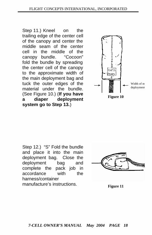
Step 11.) Kneel on the trailing edge of the center cell of the canopy and center the middle seam of the center cell in the middle of the canopy bundle. “Cocoon” fold the bundle by spreading the center cell of the canopy to the approximate width of the main deployment bag and tuck the outer edges of the material under the bundle. (See Figure 10.) (If you have a diaper deployment system go to Step 13.)
Width of maindeployment bag
Figure 10
Step 12.) “S” Fold the bundle and place it into the main deployment bag. Close the deployment bag and complete the pack job in accordance with the harness/container manufacture’s instructions. Figure 11

FLIGHT CONCEPTS INTERNATIONAL, INCORPORATED
7-CELL OWNER’S MANUAL May 2004 PAGE 19
Step 13.) After you finish the cocoon in the previous step. "S' fold the canopy and leaving the diaper on top with the lines under the canopy. Separate the line groups slightly and Spread the diaper out to each side. The cocoon width should be as wide as the diaper. (See Figure 12.)
Figure 12

FLIGHT CONCEPTS INTERNATIONAL, INCORPORATED
7-CELL OWNER’S MANUAL May 2004 PAGE 20
Step 14.) Fold the diaper under the canopy and lock it with a 3 inch bite of lines. (See Figure 13.)
Figure 13

FLIGHT CONCEPTS INTERNATIONAL, INCORPORATED
7-CELL OWNER’S MANUAL May 2004 PAGE 21
Step 15.) "S" fold the balance of the lines into the pouch on the top of the diaper.(See Figure 14.)
Figure 14

FLIGHT CONCEPTS INTERNATIONAL, INCORPORATED
7-CELL OWNER’S MANUAL May 2004 PAGE 22
Step 16.) Pick up the canopy, flip it over 180 degrees lay it into the container with the line pouch down in the pack tray. (See Figure 15.)
Figure 15

FLIGHT CONCEPTS INTERNATIONAL, INCORPORATED
7-CELL OWNER’S MANUAL May 2004 PAGE 23
Step 17.) This will put the locking stow up, place the diaper against the reserve container with the risers and lines along the side of the main container. (See Figure 16.)
Figure 16

FLIGHT CONCEPTS INTERNATIONAL, INCORPORATED
7-CELL OWNER’S MANUAL May 2004 PAGE 24
Step 18.) Dress the canopy to the top making the width the same as the pack tray on the main container. (See Figure 17.)
Figure 17

FLIGHT CONCEPTS INTERNATIONAL, INCORPORATED
7-CELL OWNER’S MANUAL May 2004 PAGE 25
Step 19.) Roll the canopy from the top towards the diaper. (See Figure 18.)
Figure 18

FLIGHT CONCEPTS INTERNATIONAL, INCORPORATED
7-CELL OWNER’S MANUAL May 2004 PAGE 26
Step 19.) Clear the retractable bridle, (to insure the bridle is clear you should see three metal rings) and close the container according to the manufactures instructions. (See Figure 19.)
Figure 19

FLIGHT CONCEPTS INTERNATIONAL, INCORPORATED
7-CELL OWNER’S MANUAL May 2004 PAGE 27
It is recommended that no novice jumper or inexperienced packer use this product. Misuse of the diaper or mis-packing the diaper could result in VERY HARD OPENINGS. These openings could cause DEATH or SERIOUS INJURY to the user and or severely damage the canopy. Please consult the manufacture for further instructions regarding the use of this product.

FLIGHT CONCEPTS INTERNATIONAL, INCORPORATED
7-CELL OWNER’S MANUAL May 2004 PAGE 28
OPERATING INSTRUCTIONS and LIMITATIONS
1. Although it is not always possible, it is highly desirable to have a good “face to earth” body position for the deployment of a main parachute. It is considered ideal to be slightly head high during and just after pilot-chute deployment. During the deployment, try to keep your shoulders as level as possible to help keep the left and right line groups loading evenly during deployment.
2. As the opening canopy pulls you head high, visually check the canopy to insure that the deployment is complete. Grasp the control toggles and pull them down sharply to release the brakes. If there is an end cell closure, or if the slider has not come all the way down the lines to the connector links, pump the control toggles by pulling them downward and returning them to full flight. This will usually clear any end cells closure and/or bring the slider down. Repeat if necessary.
3. As soon as possible after releasing the brakes conduct a control check to find the stall point of the canopy by pulling down the toggles slowly until you feel the canopy stop flying and start to "fall off" backwards. (Recover from the stall by smoothly bringing the toggles back up to shoulder level.)
4. A properly deployed and functioning canopy can be controlled with the control toggles by simply pulling down on the right toggle to turn right or pulling down on the left toggle to turn left. As long as one toggle is pulled down further than the other toggle the canopy will continue to turn in the direction of the lowest toggle. The further the toggle is pulled down, the faster the turn will be. Stalls and turns should be executed only when altitude permits. WARNING! no stalls below 1000 feet, and no turns should be done below 500 feet. (Except for minor course corrections on final approach.)

FLIGHT CONCEPTS INTERNATIONAL, INCORPORATED
7-CELL OWNER’S MANUAL May 2004 PAGE 29
5. A soft landing can usually be made by landing into the wind, and using a "Flaring Technique". This procedure is accomplished by pulling both control toggles downward smoothly to the full brake position just before landing. (Full brake position is usually with the toggles just above the stall point.) With the canopy facing into the wind and at full flight (toggles up as far as you can reach) start the flare when your feet are approximately 10-12 feet off the ground (depending upon the speed of the wind) smoothly bring the toggles down to the full brake position. When this is done correctly, the canopy will immediately change its angle of attack and this flattening of its angle of attack will allow for a very soft landing.
6. Varying wind speeds and other weather conditions may dictate variations of this technique. When in no wind conditions, it may be helpful to start the flare about six feet higher and then bring the toggles down just slightly slower, thus allowing the canopy more time to slow it's forward speed before landing. In higher wind conditions it may not be necessary to bring the toggles down quite as far to produce a flared landing.

FLIGHT CONCEPTS INTERNATIONAL, INCORPORATED
7-CELL OWNER’S MANUAL May 2004 PAGE 30
7. If an emergency situation has left you with a broken control line, it is possible to control the canopy by pulling down on the rear risers. The canopy will turn in the direction of the riser being pulled downward. However, you must be very cautious when attempting a flared landing with the rear risers, particularly when one brake is still set. WARNING! A riser flare can produce a very sudden stall, and it only takes a few inches of pulling to cause a stall. For this reason, the rear riser-flare should only be attempted in an emergency situation and ONLY if there has been ample time and altitude to practice the maneuver prior to landing. Under no circumstances should anyone try this maneuver unless they have practiced it at a SAFE ALTITUDE, furthermore it is recommended that only the very experienced skydiver ever attempt this type of landing.
8. After landing, the canopy will normally deflate if there is little or no wind. However, if the wind is strong, there still exists the danger of being dragged by the inflated canopy. If you are landing in strong winds, release one of the toggles immediately upon landing, and pull the other toggle (hand over hand if necessary) until the canopy has fully deflated.
9. Avoid landing downwind of trees or large buildings. Large ground objects produce turbulence which can be dangerous to a parachutist on final approach. It is considered good practice to fly your canopy at quarter-brakes if you expect to encounter turbulence.

FLIGHT CONCEPTS INTERNATIONAL, INCORPORATED
7-CELL OWNER’S MANUAL May 2004 PAGE 31
CANOPY CARE These suggestions have been provided to help you prolong the life of your parachuting equipment.
1. It is very important to have the trim checked on your canopy every 200 to 300 jumps. If the trim is out of tolerance by more that 1” to 1.5”. please consult FCI before continuing to use this product. (Please see the Trim Specification section of this manual for further information.)
2. Avoid dragging any part of the parachute across the ground. Do not pack on rough surfaces, such as concrete.
3. Do not leave the canopy exposed in the sun any longer than is absolutely necessary.
4. Do not wash the canopy. Over time it will increase the porosity, which will reduce the performance of the parachute. If it is necessary to remove grease spots, or any other type of stains, use mineral spirits on small areas.
5. If you must store your gear for a prolonged time frame, store the canopies, unpacked, in plastic bags. Insure the storage room is dry and that it has a constant moderate temperature to prevent mildew and damage from extreme heat.
6. Do not use Ripstop Tape or any other material that includes gum or other adhesives to make small repairs.

FLIGHT CONCEPTS INTERNATIONAL, INCORPORATED
7-CELL OWNER’S MANUAL May 2004 PAGE 32
WARNING - DISCLAIMER - NO WARRANTIES
!!The user assumes all risk!! This Flight Concepts International, Incorporated product is a high performance parachute. Serious injury or death can result from the use, attempted use, or misuse of this parachute, regardless of how it was maintained, packed, or deployed. This product is sold without warranty or suitability for any particular purpose, either expressed or implied. The manufacturer does not guarantee the reliability, dependability, or performance of this product. Furthermore, no one should attempt to use this product, or wear it as a parachute unless that person has received training in the use of this type of parachute by a qualified Instructor.
Additionally, it is understood and agreed upon that by the use of this product by the Buyer or any other subsequent user of this product, that the manufacturer and the seller shall not be deemed or held accountable, upon or under any guarantees or warranties, expressed or implied, statutory, by operation of law or otherwise, beyond that expressed herein. It is further understood that the purchase or use of this product constitutes an assumption of any and all risk associated with such use. If the Buyer is unable to accept these conditions , he/she may return the product for a complete refund within fifteen (15) days of the original purchase.