6ts series stainless steel submersible pumps kit program · kit program 6ts series 3 brand labeling...
TRANSCRIPT
K I T P R O G R A M 6TS SERIES
Contents Page Radial Flow KIT Descriptions 2 – Suction Bracket KIT – First-Stage KIT – Intermediate Stage KIT – Shaft/Strap/Cable-Guard KIT – Discharge KIT – Brand Labeling KIT – Exploded Parts View
Mixed Flow KIT Descriptions 3 – Suction Bracket KIT – First-Stage KIT – Intermediate Stage KIT – Shaft/Strap/Cable-Guard KIT – Discharge KIT – Brand Labeling KIT – Exploded Parts View
Spacer Charts 7 – Radial Flow – Mixed Flow
70 Series Perf Curves and Build Charts 10
90 Series Perf Curves and Build Charts 15
140 Series Perf Curves and Build Charts 20
115 Series Perf Curves and Build Charts 25
155 Series Perf Curves and Build Charts 30
230 Series Perf Curves and Build Charts 35
300 Series Perf Curves and Build Charts 40
Assembly Instructions Step-by-Step, Radial 45
Assembly Instructions Step-by-Step, Mixed 52
Shaft Cut-off and Staightening Instruction 60
Strap Cut-off and Forming 61
Repair Parts 63
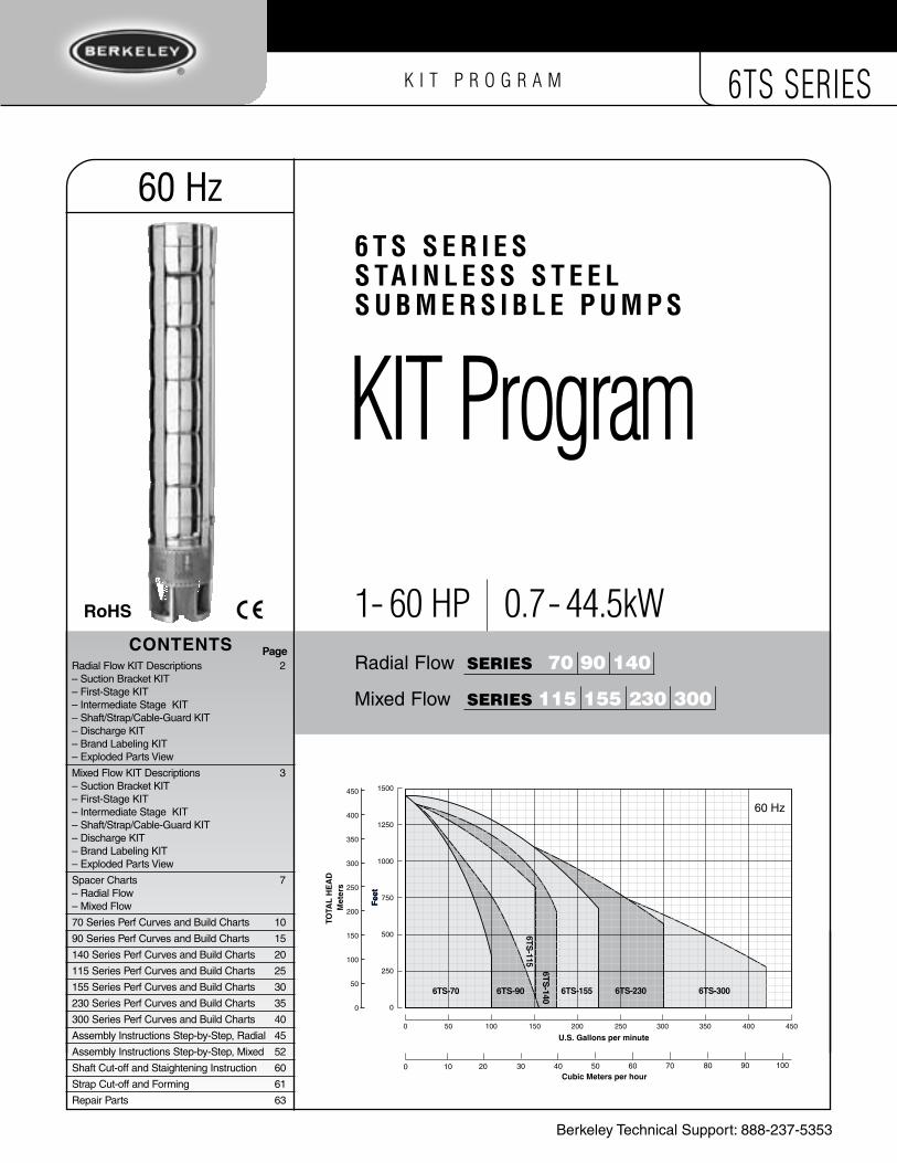
6 T S S e r i e SS Ta i n l e S S S T e e lS u b m e r S i b l e P u m P S
1 - 60 HP 0.7 - 44.5kW
KIT Program
0 50 100 150 200 250 300 350 400 450Capacity − USgpm
0 10 20 30 40 50 60 70 80 90 100
Capacity − m3/h
0
50
100
150
200
250
300
350
400
450
Head
− m
1,500
1,250
1,000
750
500
250
0
Head
− ft
0 50 100 150 200 250 300
0 10 20 30 40 50 60 70Capacity − m3/h
0
50
100
150
200
250
300
350
400
450
Hea
d −
m
1,500
1,250
1,000
750
500
250
0
Hea
d −
ft
60 Hz
1500
1250
1000
750
500
250
0
450
400
350
300
250
200
150
100
50
0
TOTA
L H
EA
D
Fee
tF
eet
0 10 20 30 40 50 60 70 80 90 100
U.S. Gallons per minute
Cubic Meters per hour
0 50 100 150 200 250 300 350 400 450
6TS-70 6TS-90
Met
ers
6TS-230 6TS-3006TS-155
6TS-140
6TS-115
60 Hz
Radial Flow SerieS 70 90 140
Mixed Flow SerieS 115 155 230 300
Berkeley Technical Support: 888-237-5353
RoHs

Radial Flow exploded View 60 Hz
First-stage KIt
Intermediate-stage KIt
shaft /strap/Cable-Guard KIt
Discharge KIt
KIT 6TS-D3NPTKIT 6TS-D3BSP
KIT 6TS-70FSTKIT 6TS-90FSTKIT 6TS-140FST
KIT 6TS-70MIDKIT 6TS-90MIDKIT 6TS-140MID
raDial FlOW COmPOnenT KiTS – 70, 90 and 140 Series suction Bracket KIt
KIT 6TS-BKT4*KIT 6TS-BKT6
1. Discharge
2. Check Valve Poppet
3. Check Valve Flange
4. Stack Compression Capscrew
5. Stack Compression Washer
6. Bearing Journal
7. Guide Housing Assembly
8. Stainless Washer
9. Fiber Washer
10. Thrust Washer
11. Bowl with Diffuser
12. Discharge Shaft Spacer
13. Impeller
14. Stage Spacer
15. First Stage Bowl w/o Diffuser
16. Inlet Shaft Spacer
*16a.Inlet Shaft Spacer–17.04mm
17. Strap Nut
18. Star Lock Washer
19. Strap Capscrew
20. Strap
21. Cable Guard Bracket
22. Cable Screen
23. Suction Screen
24. Suction Bracket
25. Coupling Guard
26. Shaft
27. Coupling
28. Coupling Set Screws
29. Hex Bolts
30. Split Washers
31. Screws – Suction Screen
Key Key Key Key no. Part Description no. Part Description no. Part Description no. Part Description
Brand Labeling KIt
LK-BKNameplate, Labels and Decals
KIT BERKELEY
3
1718
19
25 20
28
27
26
6
54
22 7
2
1
89
21
21
16
11
11
13
12
13
15
14
10
5021 0505
24
23
31
29
30
16a*
21
21
23
31
6
54 17
18
19
25 24
28
27
29
30
8910
16a*
13
14
11
20
26
22
12
15
3
7
16
ab
C
D
rST
YY1
C1
J
KJ1
KIT 6TS-70/90/140SKIT 6TS-70/90/140MKIT 6TS-70/90/140L
K I T P R O G R A M 6TS SERIES
2
* BKT4 includes additional 17.04 mm spacer #16a (M14054); needed due to bracket length difference versus BKT6.

K I T P R O G R A M 6TS SERIES
3
Brand Labeling KIt
LK-BKNameplate, Labels and Decals
KIT BERKELEY
Mixed Flow exploded View 60 Hz
First-stage KIt
Intermediate-stage KIt
shaft /strap/Cable-Guard KIt
Discharge KIt
1
25
26
27
29
28
3
2
22
67
22
23
19a*
9
9
11
15
16
1718
21
20
24
121314
10
54
8
8
19
8
5020 0505
3031
32
3
7
11
15 20
8
19
9
10
8
27
2321
1
2
KIT 6TS-115-300SKIT 6TS-115-300MKIT 6TS-115-300L
KIT 6TS-D3NPTKIT 6TS-D3BSPKIT 6TS-D4NPTKIT 6TS-D4BSP
KIT 6TS-115FSTKIT 6TS-155FSTKIT 6TS-230FSTKIT 6TS-300FST
KIT 6TS-115MIDKIT 6TS-155MIDKIT 6TS-230MIDKIT 6TS-300MID
miXeD FlOW COmPOnenT KiTS – 115, 155, 230 and 300 Series suction Bracket KIt
KIT 6TS-BKT4*KIT 6TS-BKT6
1. Discharge
2. Check Valve Poppet
3. Top Bowl
4. Stack Compression Capscrew
5. Stack Compression Washer
6. Bearing Journal
7. Discharge Shaft Spacer
8. Impeller
9. Bowl w/Diffuser
10. Stage Spacer
11. Distance Sleeve
12. Stainless Washer
13. Fiber Washer
14. Thrust Washer
15. Thrust Shaft Spacer
16. Strap Nut
17. Star Lock Washer
18. Strap Capscrew
19. Inlet Shaft Spacer
19a. Inlet Shaft Spacer–17.04mm
20. First Stage Adapter
21. Strap
22. Cable Guard Bracket
23. Cable Screen
24. Suction Screen
25. Suction Bracket
26. Coupling Guard
27. Shaft
28. Coupling
29. Coupling Set Screws
30. Hex Bolts
31. Split Washers
32. Screws – Suction Screen
Key Key Key Key no. Part Description no. Part Description no. Part Description no. Part Description
26
29
28
22 6
1617
18
54
25
24 32
3031
19a*
121314
ab
eFGH
lmnP
uVW
YY1ZZ1
* BKT4 includes additional 17.04 mm spacer #19a (M14054); needed due to bracket length difference versus BKT6.
*

K I T P R O G R A M 6TS SERIES
4
suction Bracket KIt 60 Hz Flow Rate series Motor Motor Radial Flow Mixed Flow Dia. HP kW 70 90 140 115 155 230 300 1 0.7 – – – – – –
1.5 1.1 – – – – –
2 1.5 – –
4" 3 2.2 – –
5 3.7
7.5 5.6
10 7.5
5 3.7
7.5 5.6
10 7.5
15 11.2
6" 20 14.9
25 18.6
30 22.4 –
40 29.8 – –
50 37.3 – – –
60 44.7 – – – –
KIT KIT KIT KIT KIT
KIT
KIT KIT KIT
First-stage KIt 60 Hz Flow Rate series Motor Motor Radial Flow Mixed Flow HP kW 70 90 140 115 155 230 300 1 0.7 – – – – – –
1.5 1.1 – – – – –
2 1.5 – –
3 2.2 – –
5 3.7
7.5 5.6
10 7.5
15 11.2
20 14.9
25 18.6
30 22.4 –
40 29.8 – –
50 37.3 – – –
60 44.7 – – – –
KIT KIT KIT KIT KIT12
15
3
7
16
KIT 6TS-70FST
KIT 6TS-90FST
KIT 6TS-140FST
KIT 6TS-115FST
KIT 6TS-155FST
KIT 6TS-230FST
KIT 6TS-300FST
Radial Flow
Mixed Flow
26**
29
28
22 6
161819
54
25
24
32
8910
16a*
26**
29
28
22 6
161718
54
25
24
32
3031
19a*
121314
3
7
11
15 20
8
19
KIT KIT KIT
KIT
KIT
KIT KIT
KIT 6TS-BKT4*
KIT 6TS-BKT6ab
CC1DeFGH
a
a a
a a a a
b b b b b b b
C C1 D e F G H
Radial Flow Mixed Flow
* BKT4 includes additional 17.04mm spacer #16a and #19a (M14054); needed due to bracket length difference versus BKT6.**BKT4 does not include coupling screen #26, as it is not needed.

K I T P R O G R A M 6TS SERIES
4 5
Intermediate-stage KIt 60 Hz
KIT 6TS-70MID
KIT 6TS-90MID
KIT 6TS-140MID
KIT 6TS-115MID
KIT 6TS-155MID
KIT 6TS-230MID
KIT 6TS-300MID
Flow Rate series Motor Motor Radial Flow Mixed Flow HP kW 70 90 140 115 155 230 300 1 0.7 – – – – – –
1.5 1.1 – – – – –
2 1.5 – – – –
3 2.2 – –
5 3.7
7.5 5.6
10 7.5
15 11.2
20 14.9
25 18.6
30 22.4 –
40 29.8 – –
50 37.3 – – –
60 44.7 – – – –
KIT KIT KIT KIT KIT
9
10
8
shaft/strap/Cable-Guard KIt 60 Hz
27
2321
KIT 6TS-70/90/140S
KIT 6TS-70/90/140M
KIT 6TS-70/90/140L
KIT 6TS-115-300S
KIT 6TS-115-300M
KIT 6TS-115-300L
Flow Rate series Motor Motor Radial Flow Mixed Flow HP kW 70 90 140 115 155 230 300 1 0.7 – – – – – –
1.5 1.1 – – – – – –
2 1.5 – – – – –
3 2.2 – – –
5 3.7
7.5 5.6
10 7.5
15 11.2
20 14.9
25 18.6
30 22.4 –
40 29.8 – –
50 37.3 – – –
60 44.7 – – – –
n
KIT
KIT KIT KIT
KIT
KIT KIT
KITKIT
KIT KITKIT
KIT
KIT
KITKIT
KIT KIT
KIT
KIT
KIT
KIT
JJ1KlmnP
rSTuVW
J J1 K l m n P
u u
r u ur
r
S
T
T
T
SS V
VV
V
W
W W
Radial Flow Mixed Flow
13
14
11

6
K I T P R O G R A M 6TS SERIES
Discharge KIt 60 Hz
KIT 6TS-D3NPT
KIT 6TS-D3BSP
KIT 6TS-D4NPT
KIT 6TS-D4BSP
Flow Rate series Motor Motor Radial Flow Mixed Flow Discharge HP kW 70 90 140 115 155 230 300 1 0.7 – – – – – –
1.5 1.1 – – – – –
2 1.5 – – –
3 2.2 – – –
5 3.7 – –
7.5 5.6 – –
3" 10 7.5 – –
15 11.2 – –
20 14.9 – –
25 18.6 – –
30 22.4 – – –
40 29.8 – – – –
50 37.3 – – – – –
60 44.7 – – – – – –
5 3.7 – – – – –
7.5 5.6 – – – – –
10 7.5 – – – – –
15 11.2 – – – – –
4" 20 14.9 – – – – –
25 18.6 – – – – –
30 22.4 – – – – –
40 29.8 – – – – –
50 37.3 – – – – –
60 44.7 – – – – –
KIT
or
KIT
or
KIT
or
KIT
or
KIT
or
21
21
KIT
or
KIT
or
note: 3" and 4" Discharge are interchangeable within flow series. Chart reflects "recommended" use of discharge size with flow series.
YY1ZZ1
Y Y Y Y Y
Y1 Y1 Y1 Y1 Y1
Z
Z1
Z
Z1

K I T P R O G R A M 6TS SERIES
6 7
First-stage KIt – Radial Flow
KIT 6TS-70FST
KIT 6TS-90FST
KIT 6TS-140FST
C
DC1
6418 0611
12
16
14
Intermediate-stage KIt – Radial Flow
KIT 6TS-70MID
KIT 6TS-90MID
KIT 6TS-140MID
J
KJ1
6418 0611
12
16
14
* notICe: the inlet shaft spacers (item 16) in First stage kits are not interchangeable with the inlet shaft spacers on the 6ts Wholegoods made in Kansas City.
First stage KitRadial Flow - in. (mm)
Part number
70 Length
Part number
90 Length
Part number
140 Length
#12 Disch Shaft Spacer M14181 1.51
(38.31) M15597 1.91 (48.50) M14183 2.23
(56.64)
#16 Inlet Spacer 6" Motor* M15677 2.55
(64.75) M15596 2.62 (66.50) M15678 2.85
(72.30)
C DC1
Intermediate stage Kit
Radial Flow - in. (mm)
Part number
70 Length
Part number
90 Length
Part number
140 Length
#14 Stage Spacer M14185 1.27 (32.20) M15594 1.50 (38.00) M14186 1.75 (44.40)
J KJ1
1 2 3 4 5
1 2 3 4 5 6 7 8 9 10 11 12
inches
mm
1 2 3 4 5
1 2 3 4 5 6 7 8 9 10 11 12
inches
mm
1 2 3 4 5
1 2 3 4 5 6 7 8 9 10 11 12
inches
mm
1 2 3 4 5
1 2 3 4 5 6 7 8 9 10 11 12
inches
mm
#12 Discharge shaft spacer
#14 stage spacer
#16a Inlet shaft spacer
#16 Inlet spacer
M155941.50" (38.00 mm)
M14054(17.04 mm)
M141832.23" (56.64 mm)
M141861.75" (44.40 mm)
M156782.85" (72.30 mm)
M155962.62" (66.50 mm)
M155971.91" (48.50 mm)
suction Bracket KIt – Radial Flow
KIT 6TS-BKT421
23
31
6
54 17
18
19
25 24
28
27
29
30
8910
16a*
a
Spacer Chart – radial Flow
M141811.51" (38.31 mm)
M156772.55" (64.75 mm)
M141851.27" (32.20 mm)
BKT4 includes additional 17.04 mm spacer #16a (M14054); needed due to bracket length difference versus BKT6.

K I T P R O G R A M 6TS SERIES
8
First stage KitMixed Flow - in. (mm)
Part number
115 Length
Part number
155 Length
Part number
230 Length
Part number
300 Length
#7 Disch Shaft Spacer M14049 .62
(15.74) M14054 .67 (17.04) M14061 .58
(14.66) M14068 .40 (10.16)
#11 Distance Spacer M14048 2.89
(73.56) M14053 2.84 (72.26) M14060 2.96
(75.10) M14067 3.39 (86.15)
#15 Thrust Shaft Spacer M14047 1.36
(34.44) M14052 1.41 (35.74) M14059 1.30
(32.90) M14066 .86 (21.85)
#19 Inlet Spacer 6" Motor* M15679 3.07
(77.95) M15680 3.02 (76.65) M15681 3.12
(79.24) M15682 3.30 (83.75)
First-stage KIt – Mixed Flow
KIT 6TS-115FST
KIT 6TS-155FST
eF
KIT 6TS-230FST
KIT 6TS-300FST
GH
7
11
15
19
10
6419 0611
* notICe: the inlet shaft spacers (item 19) in First stage kits are not interchangeable with the inlet shaft spacers on the 6ts Wholegoods made in Kansas City.
e F G H
1 2 3 4 5
1 2 3 4 5 6 7 8 9 10 11 12
inches
mm
1 2 3 4 5
1 2 3 4 5 6 7 8 9 10 11 12
inches
mm
1 2 3 4 5
1 2 3 4 5 6 7 8 9 10 11 12
inches
mm
#7 Discharge shaft spacer
#19 Inlet spacer#15 thrust shaft spacer
#11 Distance spacerM14054
0.67" (17.04 mm)
M140521.41" (35.74 mm)
M140673.39" (86.15 mm)
M140490.67" (15.74 mm)
M140471.36" (34.44 mm)
M140602.96" (75.10 mm)
M140610.58" (14.66 mm)
M140591.30" (32.90 mm)
M140482.89" (73.56 mm)
M156793.07" (77.95 mm)
M156823.30" (83.75 mm)
1 2 3 4 5
1 2 3 4 5 6 7 8 9 10 11 12
inches
mm
M140680.40" (10.16 mm)
M140660.86" (21.85 mm)
M140532.84" (72.26 mm)
M156803.02" (76.65 mm)
M156813.12" (79.24 mm)
Spacer Chart – mixed Flow

K I T P R O G R A M 6TS SERIES
8 9
Intermediate-stage KIt – Mixed Flow
KIT 6TS-115MID
KIT 6TS-155MID
KIT 6TS-230MID
KIT 6TS-300MID
lmnP
7
11
15
19
10
6419 0611
Intermediate stage Kit
Mixed Flow - in. (mm)
Part number
115 Length
Part number
155 Length
Part number
230 Length
Part number
300 Length
#10 Stage Spacer M14071 4.37
(111) M14071 4.37 (111) M14071 4.37
(111) M14071 4.37 (111)
l m n P
#10 stage spacer
1 2 3 4 5
1 2 3 4 5 6 7 8 9 10 11 12
inches
mm
M140714.37" (111 mm)
Spacer Chart – mixed Flow
1 2 3 4 5
1 2 3 4 5 6 7 8 9 10 11 12
inches
mm
#19a Inlet shaft spacer
M14054(17.04 mm)
suction Bracket KIt – Mixed Flow
KIT 6TS-BKT4a
26
29
28
22 6
1617
18
54
25
24 32
3031
19a*
121314
BKT4 includes additional 17.04 mm spacer #19a (M14054); needed due to bracket length difference versus BKT6.
K I T P R O G R A M 6TS SERIES
10
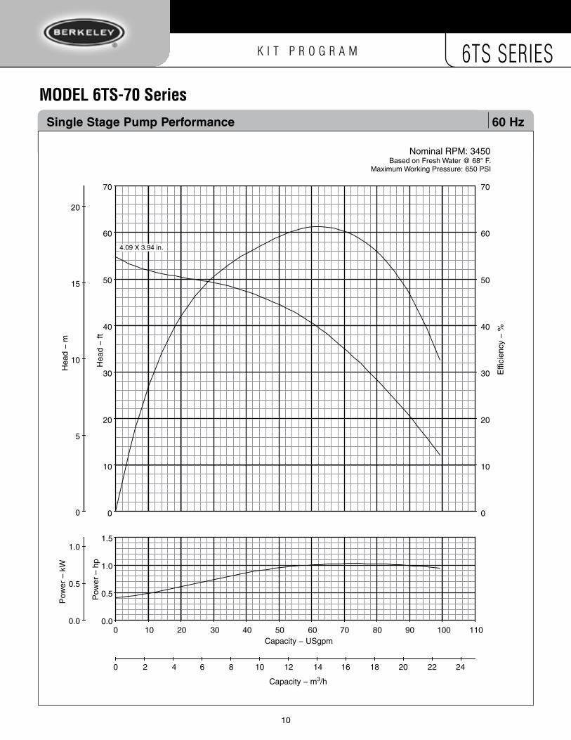
mODel 6TS-70 Series single stage Pump Performance 60 Hz
Capacity − USgpm
Capacity − m3/h
Effi
cien
cy −
%
70
60
50
40
30
20
10
0
70
60
50
40
30
20
10
0
Hea
d −
m
Hea
d −
ft
Pow
er –
kW
Pow
er –
hp
Nominal RPM: 3450Based on Fresh Water @ 68° F.
Maximum Working Pressure: 650 PSI
4.09 X 3.94 in.
20
15
10
5
0
1.0
0.5
0.0
1.5
1.0
0.5
0.0
0 2 4 6 8 10 12 14 16 18 20 22 24
0 10 20 30 40 50 60 70 80 90 100 110

K I T P R O G R A M 6TS SERIES
10 11
mODel 6TS-70 Series Pump Performance 1 - 7.5 HP (0.7 - 5.6kW) 60 Hz
0 20 40 60 80 100Capacity − USgpm
0 2 4 6 8 10 12 14 16 18 20 22Capacity − m3/h
0
20
40
60
80
100
120
140
Hea
d −
m
0
10
20
30
40
50
60
70
80
90
100
Effi
cien
cy −
%
0
50
100
150
200
250
300
350
400
450
500
Hea
d −
ft
7.5 HP (5.6 KW)
Nominal RPM: 3450Based on Fresh Water @ 68° F.
Maximum Working Pressure: 650 PSI
5 HP (3.7 KW)
3 HP (2.2 KW)
2 HP (1.5 KW)
1 HP (.07 KW)
specifications
Minimum Well I.D.
Minimum Submergence @ BEP (above inlet)
Capacity Range
Discharge
6.0 Inches (155 millimeters)
10.0 Feet (3 Meters)
35 - 90 GPM (106 - 273 L/min)
3" F NPT or BSP
See manufacturer’s data for motor cooling requirements
HP Motor P M* MD* Mtr. Pump (kW) stages size length length dia. wt. wt.
1 1 4 15.65 10.66 3.75 21 24 (0.7) (397.5) (270.8) (95) (9.5) (10.9)
2 2 4 16.98 13.62 3.75 29 26 (1.5) (431.3) (345.9) (95) (13.2) (11.8)
3 3 4 18.31 20.62 3.75 44 27 (2.2) (465.1) (523.7) (95) (20) (12.2)
5 5 4 20.96 23.62 3.75 55 31 (3.7) (532.4) (599.9) (95) (24.9) (14.1)
5 5 6 20.96 27.00 5.51 95 31 (3.7) (532.4) (685.8) (140) (43.1) (14.1)
7.5 8 4 24.95 29.62 3.75 70 37 (5.6) (633.7) (752.3) (95) (31.8) (16.8)
7.5 8 6 24.95 27.60 5.51 114 37 (5.6) (633.7) (701) (140) (51.7) (16.8)
Note: dimensions = inches (millimeters); weight = U.S. lbs. (kilograms)
outline Dimensions/Weights 60 Hz
5.63"
MD
M
P
Dates 3/2011
Section 6tsSUPERSEDES
All Previous
M* Maximum length (Motor) MD* Motor diameter (Motor)
K I T P R O G R A M 6TS SERIESK I T P R O G R A M 6TS SERIES
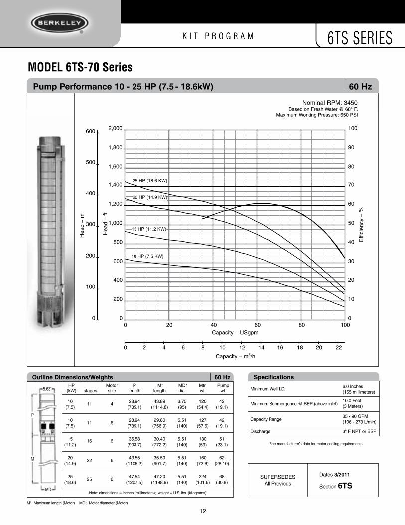
Pump Performance 10 - 25 HP (7.5 - 18.6kW) 60 Hz
mODel 6TS-70 Series
0 20 40 60 80 100Capacity − USgpm
0 2 4 6 8 10 12 14 16 18 20 22
0
100
200
300
400
500
600
Hea
d −
m
0
10
20
30
40
50
60
70
80
90
100
Effi
cien
cy −
%
0
200
400
600
800
1,000
1,200
1,400
1,600
1,800
2,000
Hea
d −
ft
Capacity − m3/h
Nominal RPM: 3450Based on Fresh Water @ 68° F.
Maximum Working Pressure: 650 PSI
15 HP (11.2 KW)
20 HP (14.9 KW)
10 HP (7.5 KW)
25 HP (18.6 KW)
specifications
Minimum Well I.D.
Minimum Submergence @ BEP (above inlet)
Capacity Range
Discharge
6.0 Inches (155 millimeters)
10.0 Feet (3 Meters)
35 - 90 GPM (106 - 273 L/min)
3" F NPT or BSP
See manufacturer’s data for motor cooling requirements
HP Motor P M* MD* Mtr. Pump (kW) stages size length length dia. wt. wt.
10 11 4 28.94 43.89 3.75 120 42 (7.5) (735.1) (1114.8) (95) (54.4) (19.1)
10 11 6 28.94 29.80 5.51 127 42 (7.5) (735.1) (756.9) (140) (57.6) (19.1)
15 16 6 35.58 30.40 5.51 130 51 (11.2) (903.7) (772.2) (140) (59) (23.1)
20 22 6 43.55 35.50 5.51 160 62 (14.9) (1106.2) (901.7) (140) (72.6) (28.10)
25 25 6 47.54 47.20 5.51 224 68 (18.6) (1207.5) (1198.9) (140) (101.6) (30.8)
Note: dimensions = inches (millimeters); weight = U.S. lbs. (kilograms)
outline Dimensions/Weights 60 Hz
5.63"
MD
M
P
Dates 3/2011
Section 6tsSUPERSEDES
All Previous
M* Maximum length (Motor) MD* Motor diameter (Motor)
12

K I T P R O G R A M 6TS SERIES
13
Pump KIt Build Chart – 70 series Radial Flow 60 Hz60 Hz – 70 series
no. of stages 1 2 3 4 5 6 7 8 9
Horsepower 1HP 2HP 3HP 5HP 7.5HP 10HP
Kilowatts 0.7kW 1.5kW 2.2kW 3.7kW 5.6kW 17.5kW
number of KIts Required – per no. of stages
KIT 6TS-BKT4a1 1 1 1 1
KIT 6TS-BKT6b KIT 6TS-70FSTC 1 1 1 1 1
KIT 6TS-70MIDJ 1 2 3 4 5 6 7 8 9
KIT 6TS-70/90/140Sr 1 1 1 1 1 1
1 1 1 1 1 KIT 6TS-D3NPTY KIT 6TS-D3BSP
▲▲
▲
Pump Cut-off Chart – 70 series Radial Flow 60 Hz KIt 6ts-70 (short)
no. of stages 1 2
Horsepower 1HP 2HP 3HP 5HP 7.5HP
3 4 5 6 7 8 9
Kilowatts 0.7kW 1.5 kW 2.2kW 3.7kW 5.6kW
LenGtH In InCHes (millimeters)
Shaft Cut-off
Straps Cut-off**
Straps Formed
Cable-Guard Cut-off
6.91 (175.5)11.32
(287.6)10.41
(264.5)14.78
(375.5)
8.23 (209.1)12.65
(321.4)11.74
(298.3)16.11
(409.3)
9.56 (242.9)13.98
(355.1)13.07 (332)17.44 (443)
10.89 (276.6)15.31
(388.9)14.40
(365.8)18.77
(476.8)
12.22 (310.4)16.64
(422.6)15.73
(399.5)20.10
(510.5)
13.55 (344.2)17.97
(456.4)17.06
(433.3)21.43
(544.3)
14.88 (377.9)19.30
(490.1)18.39 (467)22.76 (578)
▲▲
▲
r
16.21 (411.7)20.62
(523.9)19.72
(500.8)24.09
(611.8)
17.54 (445.4)21.95
(557.6)21.04
(534.5)25.41
(645.5)
**Length includes "J-bend".
note: If using the 4 x 6 suction bracket, the shaft length must be increased by 0.67 inches (17 mm).
Y1
10HP
17.5kW
Pump Performance 1-7.5 HP
mODel e6TS-70 GPm
K I T P R O G R A M 6TS SERIES
14
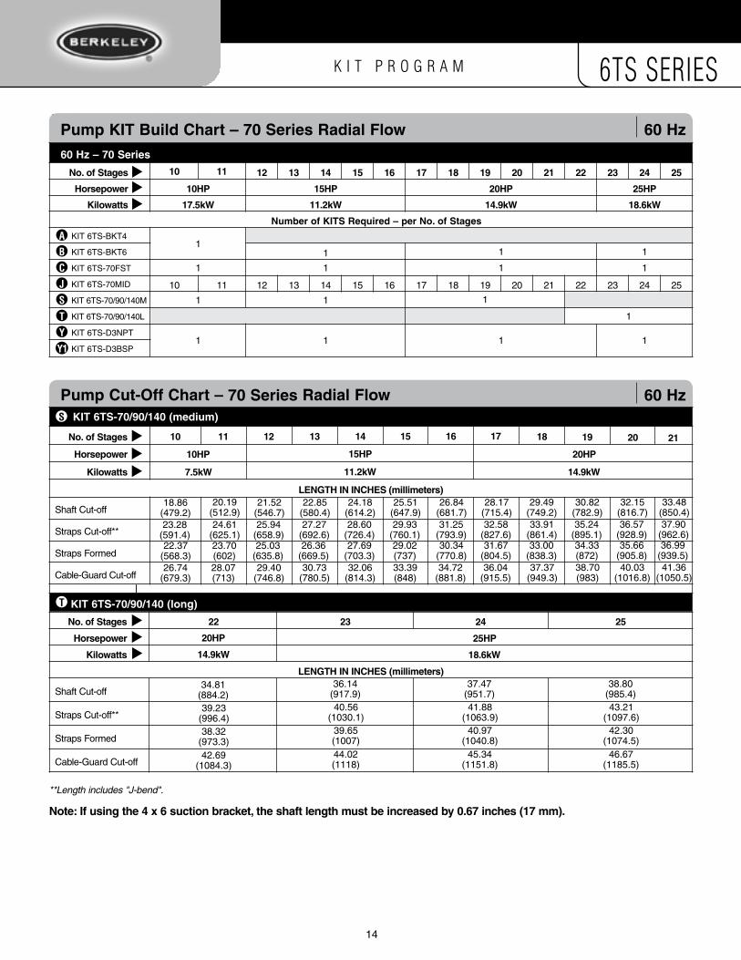
Pump KIt Build Chart – 70 series Radial Flow 60 Hz60 Hz – 70 series
no. of stages 10 11 12 13 14 15 16 17 18 19 20 21 22 23 24 25
Horsepower 10HP 15HP 20HP 25HP
Kilowatts 17.5kW 11.2kW 14.9kW 18.6kW
number of KIts Required – per no. of stages
KIT 6TS-BKT4a1
KIT 6TS-BKT6b 1 1 1
KIT 6TS-70FSTC 1 1 1 1
KIT 6TS-70MIDJ 10 11 12 13 14 15 16 17 18 19 20 21 22 23 24 25
KIT 6TS-70/90/140MS 1 1
KIT 6TS-70/90/140LT 1
1 1 1 1 KIT 6TS-D3NPTY KIT 6TS-D3BSP
Pump Cut-off Chart – 70 series Radial Flow 60 Hz KIt 6ts-70/90/140 (medium)
no. of stages
Kilowatts 7.5kW 14.9kW
Horsepower 10HP 20HP
LenGtH In InCHes (millimeters)
Shaft Cut-off
Straps Cut-off**
Straps Formed
Cable-Guard Cut-off
KIt 6ts-70/90/140 (long)
no. of stages 22 23 24 25
Kilowatts 18.6kW
Horsepower 25HP
LenGtH In InCHes (millimeters)
Shaft Cut-off
Straps Cut-off**
Straps Formed
Cable-Guard Cut-off
▲▲
▲▲
▲▲
T
S
▲▲
▲
**Length includes "J-bend".
note: If using the 4 x 6 suction bracket, the shaft length must be increased by 0.67 inches (17 mm).
Y1
10 11 12 13 14 15 16 17 18 19 20 21
18.86 (479.2)
34.81 (884.2)
36.14 (917.9)
37.47 (951.7)
38.80 (985.4)
23.28 (591.4)
39.23 (996.4)
40.56 (1030.1)
41.88 (1063.9)
43.21 (1097.6)
22.37 (568.3)
38.32 (973.3)
39.65 (1007)
40.97 (1040.8)
42.30 (1074.5)
26.74 (679.3)
42.69 (1084.3)
44.02 (1118)
45.34 (1151.8)
46.67 (1185.5)
20.19 (512.9)24.61
(625.1)23.70 (602)28.07 (713)
21.52 (546.7)25.94
(658.9)25.03
(635.8)29.40
(746.8)
22.85 (580.4)27.27
(692.6)26.36
(669.5)30.73
(780.5)
24.18 (614.2)28.60
(726.4)27.69
(703.3)32.06
(814.3)
25.51 (647.9)29.93
(760.1)29.02 (737)33.39 (848)
26.84 (681.7)31.25
(793.9)30.34
(770.8)34.72
(881.8)
28.17 (715.4)32.58
(827.6)31.67
(804.5)36.04
(915.5)
29.49 (749.2)33.91
(861.4)33.00
(838.3)37.37
(949.3)
30.82 (782.9)35.24
(895.1)34.33 (872)38.70 (983)
32.15 (816.7)36.57
(928.9)35.66
(905.8)40.03
(1016.8)
33.48 (850.4)37.90
(962.6)36.99
(939.5)41.36
(1050.5)
15HP
11.2kW
20HP
14.9kW
1

K I T P R O G R A M 6TS SERIES
15
mODel 6TS-90 Series single stage Pump Performance 60 Hz
80
70
60
50
40
30
20
10
0
100
90
80
70
60
50
40
30
20
10
0
Capacity − USgpm
Capacity − m3/h
Effi
cien
cy −
%
Hea
d −
m
Hea
d −
ft
Pow
er –
kW
Pow
er –
hp
Nominal RPM: 3450Based on Fresh Water @ 68° F.
Maximum Working Pressure: 625 PSI
20
15
10
5
0
1.0
0.5
0.0
2.0
1.5
1.0
0.5
0.0
0 2 4 6 8 10 12 14 16 18 20 22 24 26 28 30 32 34 36
0 10 20 30 40 50 60 70 80 90 100 110 120 130 140 150 160
4.09 X 3.94 in.

K I T P R O G R A M 6TS SERIES
16
Pump Performance 5 - 20 HP (3.7 - 14.9kW) 60 Hz
mODel 6TS-90 Series
0 60 12040 10020 80 140 160Capacity − USgpm
0 4 8 12 16 20 24 28 32 36
Capacity − m3/h
Nominal RPM: 3450Based on Fresh Water @ 68° F.
Maximum Working Pressure: 625 PSI
300
250
200
150
100
50
0
1,000
900
800
700
600
500
400
300
200
100
0
Hea
d −
m
Hea
d −
ft
0
10
20
30
40
50
60
70
80
90
100
Effi
cien
cy −
%
20 HP (14.9 KW)
15 HP (11.2 KW)
10 HP (7.5 KW)
7.5 HP (5.6 KW)
5 HP (3.7 KW)
HP Motor P M* MD* Mtr. Pump (kW) stages size length length dia. wt. wt.
1 1 4 15.65 10.66 3.75 21 24 (0.7) (397.5) (270.8) (95) (9.5) (10.9)
2 2 4 16.98 13.62 3.75 29 26 (1.5) (431.3) (345.9) (95) (13.2) (11.8)
3 3 4 18.31 20.62 3.75 44 27 (2.2) (465.1) (523.7) (95) (20) (12.2)
5 5 4 20.96 23.62 3.75 55 31 (3.7) (532.4) (599.9) (95) (24.9) (14.1)
5 5 6 20.96 27.00 5.51 95 31 (3.7) (532.4) (685.8) (140) (43.1) (14.1)
7.5 8 4 24.95 29.62 3.75 70 37 (5.6) (633.7) (752.3) (95) (31.8) (16.8)
7.5 8 6 24.95 27.60 5.51 114 37 (5.6) (633.7) (701) (140) (51.7) (16.8)
Note: dimensions = inches (millimeters); weight = U.S. lbs. (kilograms)
outline Dimensions/Weights 60 Hz
5.63"
MD
M
P
HP Motor P M* MD* Mtr. Pump (kW) stages size length length dia. wt. wt.
5 3 4 18.43 23.62 3.75 55 31.6 (3.7) (468) (599.9) (95.3) (25.0) (14.4)
5 3 6 18.43 27 5.51 95 31.6 (3.7) (468) (685.8) (140) (43.2) (14.4)
7.5 5 4 21.54 29.62 3.75 70 35.9 (5.6) (547) (752.3) (95.3) (31.8) (16.3)
7.5 5 6 21.54 27.6 5.51 114 35.9 (5.6) (547) (701) (140) (51.8) (16.3)
10 7 4 24.65 43.89 3.75 120 40.2 (7.5) (626) (1114.8) (95.3) (54.5) (18.3)
10 7 6 24.65 29.8 5.51 127 40.2 (7.5) (626) (756.9) (140) (57.7) (18.3)
15 11 6 30.87 30.4 5.51 130 48.7 (11.2) (784) (772.2) (140) (59.1) (22.1)
20 15 6 37.09 35.5 5.51 160 57.3 (14.9) (942) (901.7) (140) (72.7) (26)
Note: dimensions = inches (millimeters); weight = U.S. lbs. (kilograms)
outline Dimensions/Weights 60 Hz
5.63"
MD
M
P
specifications
Minimum Well I.D.
Minimum Submergence @ BEP (above inlet)
Capacity Range
Discharge
6.0 Inches (155 millimeters)
10.0 Feet (3 Meters)
45 - 115 GPM (170 - 435 L/min)
3" F NPT or BSP
See manufacturer’s data for motor cooling requirements
Dates 3/2011
Section 6tsSUPERSEDES
All Previous
M* Maximum length (Motor) MD* Motor diameter (Motor)

K I T P R O G R A M 6TS SERIES
16 17
Pump Performance 25 - 30 HP (18.6 - 22.4kW) 60 Hz
mODel 6TS-90 Series
0
10
20
30
40
50
60
70
80
90
100
Effi
cien
cy −
%
0 60 12040 10020 80 140 160Capacity − USgpm
0 4 8 12 16 20 24 28 32 36
Capacity − m3/h
Nominal RPM: 3450Based on Fresh Water @ 68° F.
Maximum Working Pressure: 625 PSI
0
50
100
150
200
250
300
350
400
450
Hea
d −
m
150
300
450
600
750
900
1,050
1,200
1,350
1,500
Hea
d −
ft
25 HP (18.6 KW)
30 HP (22.4 KW)
HP Motor P M* MD* Mtr. Pump (kW) stages size length length dia. wt. wt.
1 1 4 15.65 10.66 3.75 21 24 (0.7) (397.5) (270.8) (95) (9.5) (10.9)
2 2 4 16.98 13.62 3.75 29 26 (1.5) (431.3) (345.9) (95) (13.2) (11.8)
3 3 4 18.31 20.62 3.75 44 27 (2.2) (465.1) (523.7) (95) (20) (12.2)
5 5 4 20.96 23.62 3.75 55 31 (3.7) (532.4) (599.9) (95) (24.9) (14.1)
5 5 6 20.96 27.00 5.51 95 31 (3.7) (532.4) (685.8) (140) (43.1) (14.1)
7.5 8 4 24.95 29.62 3.75 70 37 (5.6) (633.7) (752.3) (95) (31.8) (16.8)
7.5 8 6 24.95 27.60 5.51 114 37 (5.6) (633.7) (701) (140) (51.7) (16.8)
Note: dimensions = inches (millimeters); weight = U.S. lbs. (kilograms)
outline Dimensions/Weights 60 Hz
5.63"
MD
M
P
HP Motor P M* MD* Mtr. Pump (kW) stages size length length dia. wt. wt.
25 18 6 41.77 47.2 5.51 224 63.7
(18.6) (1061) (1198.9) (140) (101.8) (29.0)
30 22 6 47.99 49.5 5.51 236 72.3
(22.4) (1219) (1257.3) (140) (107.3) (32.9)
Note: dimensions = inches (millimeters); weight = U.S. lbs. (kilograms)
outline Dimensions/Weights 60 Hz
5.63"
MD
M
P
specifications
Minimum Well I.D.
Minimum Submergence @ BEP (above inlet)
Capacity Range
Discharge
6.0 Inches (155 millimeters)
10.0 Feet (3 Meters)
45 - 115 GPM (170 - 435 L/min)
3" F NPT or BSP
See manufacturer’s data for motor cooling requirements
Dates 3/2011
Section 6tsSUPERSEDES
All Previous
M* Maximum length (Motor) MD* Motor diameter (Motor)

K I T P R O G R A M 6TS SERIES
18
Pump KIt Build Chart – 90 series Radial Flow 60 Hz60 Hz – 90 series
no. of stages 3 4 5 6 7 8 9 10 11 12 13 14 15
Horsepower 7.5HP 15HP 20HP
Kilowatts 5.6kW 11.2kW 14.9kW
number of KIts Required – per no. of stages
KIT 6TS-BKT4a1
KIT 6TS-BKT6b1
KIT 6TS-90FST 1 1
KIT 6TS-90MID 3 4 5 6 8 9 10 11 12 13 14 15
KIT 6TS-70/90/140Sr 1
KIT 6TS-70/90/140MS
1 1 KIT 6TS-D3NPTY KIT 6TS-D3BSP
▲▲
▲ 5HP
3.7kW
10HP
7.5kW
1
1
1
1 1
1
1
7
1
1 1
1
1
Pump Cut-off Chart – 90 series Radial Flow 60 Hz KIt 6ts-70/90/140 (short)r
no. of stages 3 4 5 6 7 8 9 10 11 12 13 14
Kilowatts 3.7kW 5.6kW 18.6kW14.9kW
Horsepower 5HP 7.5HP 25HP20HP
LenGtH In InCHes (millimeters)
Shaft Cut-off12.17 (309)
13.70 (348)
15.28 (388)
16.81 (427)
21.50 (546)
29.25 (743)
Straps Cut-off**24.41
(417.1)17.96
(456.1)19.53
(496.1)21.07
(535.1)
25.75 (654.1)
31.97 (812.1)
Straps Formed15.51 (394)
17.05 (433)
18.62 (473)
20.16 (512)
Cable-Guard Cut-off19.76 (502)
21.30 (541)
22.87 (581)
24.41 (620)
▲▲
▲
15
7.5kW
10HP
11.2kW
15HP
19.92 (506)
24.61 (625)
26.14 (664)
27.72 (704)
24.18 (614.1)
28.86 (733.1)
30.40 (772.1)
33.51 (851.1)
23.27 (591)
24.84 (631)
27.95 (710)
29.49 (749)
31.06 (789)
32.60 (828)
27.52 (699)
29.09 (739)
32.21 (818)
33.74 (857)
35.32 (897)
36.85 (936)
23.03 (585)27.29
(693.1)26.38 (670)30.63 (778)
Shaft Cut-off
Straps Cut-off**
Straps Formed
Cable-Guard Cut-off
18.39 (467)22.64
(575.1)21.73 (552)25.98 (660)
10.6 (269)14.9
(317.1)14.0 (354)18.2 (462)
KIt 6ts-70/90/140 (medium)S
**Length includes "J-bend".
note: If using the 4 x 6 suction bracket, the shaft length must be increased by 0.67 inches (17 mm).
Y1
C1
J11
1

K I T P R O G R A M 6TS SERIES
18 19
Pump Cut-off Chart – 90 series Radial Flow 60 Hz KIt 6ts-70/90/140 (medium)
no. of stages 16 17 18 19 20 21 22
Kilowatts 18.6kW 22.4kW
Horsepower 25HP 30HP
LenGtH In InCHes (millimeters)
Shaft Cut-off32.36 (822)
33.94 (862)
Straps Cut-off**36.62
(930.1)38.19
(970.1)
Straps Formed35.71 (907)
37.28 (947)
Cable-Guard Cut-off39.96 (1015)
41.54 (1055)
▲▲
▲
S
Shaft Cut-off37.05 (941)
38.58 (980)
40.16 (1020)
Straps Cut-off**41.30
(1049.1)42.84
(1088.1)44.41
(1128.1)
Straps Formed40.39 (1026)
41.93 (1065)
43.50 (1105)
Cable-Guard Cut-off44.65 (1134)
46.18 (1173)
47.76 (1213)
Pump KIt Build Chart – 90 series Radial Flow 60 Hz60 Hz – 90 series
no. of stages 16 17 18 19
Horsepower 25HP
Kilowatts 18.6kW
number of KIts Required – per no. of stages
KIT 6TS-BKT4a KIT 6TS-BKT6b
1 1
KIT 6TS-90FST 1 1
KIT 6TS-90MID 16 17 18 19 20
KIT 6TS-70/90/140MS KIT 6TS-70/90/140LT KIT 6TS-D3NPTY
1 KIT 6TS-D3BSP
▲▲
▲
20 21 22
30HP
22.4kW
1
1
1
21 22
30.83 (783)35.08
(891.1)34.17 (868)38.43 (976)
35.47 (901)39.73
(1009.1)38.82 (986)43.07 (1094)
KIt 6ts-70/90/140 (long)T
**Length includes "J-bend".
note: If using the 4 x 6 suction bracket, the shaft length must be increased by 0.67 inches (17 mm).
Y1
J1
C1

K I T P R O G R A M 6TS SERIES
20
mODel 6TS-140 Series single stage Pump Performance 60 Hz
Nominal RPM: 3450Based on Fresh Water @ 68° F.
Maximum Working Pressure: 650 PSI
70
60
50
40
30
20
10
0
Hea
d −
m
Hea
d −
ft
Pow
er –
kW
Pow
er –
hp
20
15
10
5
0
1.5
1.0
0.5
0.0
2.5
2.0
1.5
1.0
0.5
0.0
Effi
cien
cy −
%
70
60
50
40
30
20
10
0
Capacity − USgpm
Capacity − m3/h
0 5 10 15 20 25 30 35 40 45 50
0 25 50 75 100 125 150 175 200 225
4.09 X 3.94 in.

K I T P R O G R A M 6TS SERIES
20 21
Pump Performance 3 - 15 HP (2.2 - 11.2kW) 60 Hz
mODel 6TS-140 Series
Capacity − m3/h
Nominal RPM: 3450Based on Fresh Water @ 68° F.
Maximum Working Pressure: 650 PSI
0 20 40 60 80 100 120 140 160 180Capacity − USgpm
0 2 4 6 8 10 12 14 16 18 20 22 24 26 28 30 32 34 36 38 40
0
20
40
60
80
100
120
140
Hea
d −
m
0
10
20
30
40
50
60
70
80
90
100
Effi
cien
cy −
%
0
50
100
150
200
250
300
350
400
450
500
Hea
d −
ft
7.5 HP (5.6 KW)
5 HP (3.7 KW)
3 HP (2.2 KW)
15 HP (11.2 KW)
10 HP (7.5 KW)
specifications
Minimum Well I.D.
Minimum Submergence @ BEP (above inlet)
Capacity Range
Discharge
6.0 Inches (155 millimeters)
10.0 Feet (3 Meters)
65 - 170 GPM (190 - 511 L/min)
3" F NPT or BSP
See manufacturer’s data for motor cooling requirements
HP Motor P M* MD* Mtr. Pump (kW) stages size length length dia. wt. wt.
1 1 4 15.65 10.66 3.75 21 24 (0.7) (397.5) (270.8) (95) (9.5) (10.9)
2 2 4 16.98 13.62 3.75 29 26 (1.5) (431.3) (345.9) (95) (13.2) (11.8)
3 3 4 18.31 20.62 3.75 44 27 (2.2) (465.1) (523.7) (95) (20) (12.2)
5 5 4 20.96 23.62 3.75 55 31 (3.7) (532.4) (599.9) (95) (24.9) (14.1)
5 5 6 20.96 27.00 5.51 95 31 (3.7) (532.4) (685.8) (140) (43.1) (14.1)
7.5 8 4 24.95 29.62 3.75 70 37 (5.6) (633.7) (752.3) (95) (31.8) (16.8)
7.5 8 6 24.95 27.60 5.51 114 37 (5.6) (633.7) (701) (140) (51.7) (16.8)
Note: dimensions = inches (millimeters); weight = U.S. lbs. (kilograms)
outline Dimensions/Weights 60 Hz
5.63"
MD
M
P
HP Motor P M* MD* Mtr. Pump (kW) stages size length length dia. wt. wt.
3 1 4 16.15 20.62 3.75 44 24.46 (2.2) (410.2) (523.7) (95) (20) (11.1)
5 2 4 17.48 23.62 3.75 55 26.92 (3.7) (444) (599.9) (95) (24.9) (12.2)
5 2 6 17.48 27.00 5.51 95 26.92 (3.7) (444) (685.8) (140) (43.1) (12.2)
7.5 3 4 18.81 29.62 3.75 70 29.38 (5.6) (477.8) (752.3) (95) (31.8) (13.3)
7.5 3 6 18.81 27.60 5.51 114 29.38 (5.6) (477.8) (701) (140) (51.7) (13.3)
10 4 4 20.14 43.89 3.75 120 31.84 (7.5) (511.6) (1114.8) (95) (54.4) (14.4)
10 4 6 20.14 29.80 5.51 127 31.84 (7.5) (511.6) (756.9) (140) (57.6) (14.4)
15 7 6 24.12 30.40 5.51 130 39.22 (11.2) (612.6) (772.2) (140) (59) (17.8)
Note: dimensions = inches (millimeters); weight = U.S. lbs. (kilograms)
outline Dimensions/Weights 60 Hz
5.63"
MD
M
P
Dates 3/2011
Section 6tsSUPERSEDES
All Previous
M* Maximum length (Motor) MD* Motor diameter (Motor)

K I T P R O G R A M 6TS SERIES
Pump Performance 20 - 50 HP (14.9 - 37.3kW) 60 Hz
mODel 6TS-140 Series
0 20 40 60 80 100 120 140 160 180
Capacity − USgpm
0 2 4 6 8 10 12 14 16 18 20 22 24 26 28 30 32 34 36 38 40
0
50
100
150
200
250
300
350
400
450
Hea
d −
m
0
10
20
30
40
50
60
70
80
90
100
Effi
cien
cy −
%
0
150
300
450
600
750
900
1,050
1,200
1,350
1,500
Hea
d −
ft 30 HP (22.4 KW)
25 HP (18.6 KW)
20 HP (14.9 KW)
50 HP (37.3 KW)
40 HP (29.8 KW)
Capacity − m3/h
Nominal RPM: 3450Based on Fresh Water @ 68° F.
Maximum Working Pressure: 650 PSI
specifications
Minimum Well I.D.
Minimum Submergence @ BEP (above inlet)
Capacity Range
Discharge
6.0 Inches (155 millimeters)
10.0 Feet (3 Meters)
65 - 170 GPM (190 - 511 L/min)
3" F NPT or BSP
See manufacturer’s data for motor cooling requirements
HP Motor P M* MD* Mtr. Pump (kW) stages size length length dia. wt. wt.
20 9 6 26.78 35.50 5.51 160 44.14 (14.9) (680.2) (901.7) (140) (72.6) (20)
25 12 6 30.77 47.20 5.51 224 51.52 (18.6) (781.6) (1198.9) (140) (101.6) (23.4)
30 14 6 33.43 49.50 5.51 236 56.44 (22.4) (849.1) (1257.3) (140) (107) (25.6)
40 19 6 40.07 50.30 5.51 239 68.74 (29.8) (1017.8) (1277.6) (140) (108.4) (31.2)
50 24 6
46.71 52.20 5.51 251 81.04 (37.3) (1186.4) (1325.9) (140) (113.9) (36.8)
Note: dimensions = inches (millimeters); weight = U.S. lbs. (kilograms)
outline Dimensions/Weights 60 Hz
5.63"
MD
M
P
Dates 3/2011
Section 6tsSUPERSEDES
All Previous
M* Maximum length (Motor) MD* Motor diameter (Motor)
22

K I T P R O G R A M 6TS SERIES
23
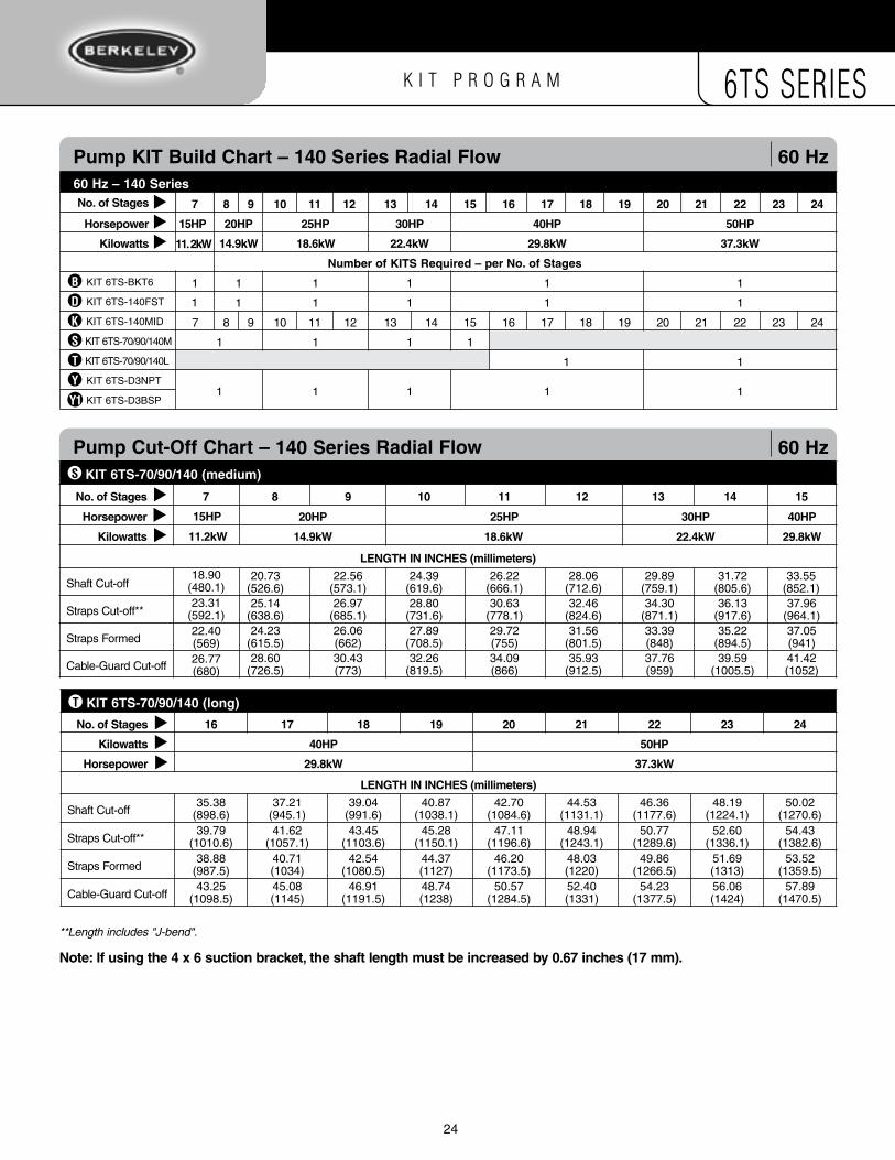
Pump KIt Build Chart – 140 series Radial Flow 60 Hz60 Hz – 140 series
no. of stages 4 5 6
Horsepower 10HP 15HP
Kilowatts 7.5kW 11.2kW
number of KIts Required – per no. of stages
KIT 6TS-BKT4a1
KIT 6TS-BKT6b KIT 6TS-140FSTD 1 11
1
1
KIT 6TS-140MIDK 4 5 6
KIT 6TS-70/90/140Sr 1 1
KIT 6TS-D3NPTY1 1
KIT 6TS-D3BSP
▲▲
▲
Pump Cut-off Chart – 140 series Radial Flow 60 Hz KIt 6ts-70/90/140 (short)
no. of stages 1 2 3 4 5 6
Kilowatts 2.2kW 3.7kW 5.6kW 7.5kW 11.2kW
Horsepower 3HP 5HP 7.5HP 10HP 15HP
LenGtH In InCHes (millimeters)
Shaft Cut-off
Straps Cut-off**
Straps Formed
Cable-Guard Cut-off
1
3HP
2.2kW
1
1
1
1
1
7.92 (201.2)12.33
(313.1)11.42 (290)15.79 (401)
2
5HP
3.7kW
1
1
2
1
1
9.75 (247.7)14.16
(359.6)13.25
(336.5)17.62
(447.5)
13.41 (340.6)17.82
(452.6)16.91
(429.5)21.28
(540.5)
15.24 (387.1)19.65
(499.1)18.74 (476)23.11 (587)
17.07 (433.6)21.48
(545.6)20.57
(522.5)24.94
(633.5)
▲▲
▲
r
**Length includes "J-bend".
note: If using the 4 x 6 suction bracket, the shaft length must be increased by 0.67 inches (17 mm).
Y1
3
7.5HP
5.6kW
1
1
3
1
1
11.58 (294.1)15.99
(406.1)15.08 (383)19.45 (494)
1
K I T P R O G R A M 6TS SERIES
24
Pump KIt Build Chart – 140 series Radial Flow 60 Hz60 Hz – 140 series no. of stages 87 9 10 11 12 13 14 15 16 17 18 19 20 21 22 23 24
Horsepower 15HP
11. 2kW
25HP 30HP 40HP 50HP
Kilowatts 18.6kW 22.4kW 29.8kW 37.3kW
number of KIts Required – per no. of stages
KIT 6TS-BKT6b 11 1 1 1 1
KIT 6TS-140FSTD 11 1 1 1 1
KIT 6TS-140MIDK 87 9 10 11 12 13 14 15 16 17 18 19 20 21 22 23 24
KIT 6TS-70/90/140MS 1 1 1 1
KIT 6TS-70/90/140LT 1 1
KIT 6TS-D3NPTY1 1 1 1 1
KIT 6TS-D3BSP
▲▲
▲
KIt 6ts-70/90/140 (long)
no. of stages 16 17 18 19 20 21 22 23 24
Kilowatts 40HP 50HP
Horsepower 29.8kW 37.3kW
LenGtH In InCHes (millimeters)
Shaft Cut-off35.38
(898.6)37.21
(945.1)39.04
(991.6)40.87
(1038.1)42.70
(1084.6)44.53
(1131.1)46.36
(1177.6)48.19
(1224.1)50.02
(1270.6)
Straps Cut-off**39.79
(1010.6)41.62
(1057.1)43.45
(1103.6)45.28
(1150.1)47.11
(1196.6)48.94
(1243.1)50.77
(1289.6)52.60
(1336.1)54.43
(1382.6)
Straps Formed38.88
(987.5)40.71 (1034)
42.54 (1080.5)
44.37 (1127)
46.20 (1173.5)
48.03 (1220)
49.86 (1266.5)
51.69 (1313)
53.52 (1359.5)
Cable-Guard Cut-off43.25
(1098.5)45.08 (1145)
46.91 (1191.5)
48.74 (1238)
50.57 (1284.5)
52.40 (1331)
54.23 (1377.5)
56.06 (1424)
57.89 (1470.5)
▲▲
▲
KIt 6ts-70/90/140 (medium)
no. of stages 87 9 10 11 12 13 14 15
Kilowatts 14.9kW 18.6kW 22.4kW
Horsepower 20HP 25HP 30HP
LenGtH In InCHes (millimeters)
Shaft Cut-off20.73
(526.6)22.56
(573.1)24.39
(619.6)26.22
(666.1)28.06
(712.6)29.89
(759.1)31.72
(805.6)33.55
(852.1)
Straps Cut-off**25.14
(638.6)26.97
(685.1)28.80
(731.6)30.63
(778.1)32.46
(824.6)34.30
(871.1)36.13
(917.6)37.96
(964.1)
Straps Formed24.23
(615.5)26.06 (662)
27.89 (708.5)
29.72 (755)
31.56 (801.5)
33.39 (848)
35.22 (894.5)
37.05 (941)
Cable-Guard Cut-off28.60
(726.5)30.43 (773)
32.26 (819.5)
34.09 (866)
35.93 (912.5)
37.76 (959)
39.59 (1005.5)
41.42 (1052)
▲▲
▲
S
T
Pump Cut-off Chart – 140 series Radial Flow 60 Hz
**Length includes "J-bend".
note: If using the 4 x 6 suction bracket, the shaft length must be increased by 0.67 inches (17 mm).
29.8kW
40HP
Y1
18.90 (480.1)23.31
(592.1)22.40 (569)26.77 (680)
15HP
11.2kW
20HP
14.9kW

K I T P R O G R A M 6TS SERIES
25
mODel 6TS-115 Series single stage Pump Performance 60 Hz
4.13 X 3.79 in.
80
70
60
50
40
30
20
10
0
Hea
d −
m
Hea
d −
ft
20
15
10
5
0
Nominal RPM: 3450Based on Fresh Water @ 68° F.
Maximum Working Pressure: 650 PSI
Effi
cien
cy −
%
80
70
60
50
40
30
20
10
0
Pow
er –
kW
Pow
er –
hp
1.5
1.0
0.5
0.0
2.5
2.0
1.5
1.0
0.5
0.0
Capacity − USgpm
Capacity − m3/h
0 5 10 15 20 25 30 35 40 45 50
0 25 50 75 100 125 150 175 200 225

K I T P R O G R A M 6TS SERIES
26
Pump Performance 2 - 10 HP (1.5 - 7.5kW) 60 Hz
mODel 6TS-115 Series
0 20 40 60 80 100 120 140 160 180Capacity − USgpm
0 2 4 6 8 10 12 14 16 18 20 22 24 26 28 30 32 34 36 38 40
0
20
40
60
80
100
120
Hea
d −
m
0
10
20
30
40
50
60
70
80
90
100
Effi
cien
cy −
%
0
40
80
120
160
200
240
280
320
360
400
Hea
d −
ft
Capacity − m3/h
Nominal RPM: 3450Based on Fresh Water @ 68° F.
Maximum Working Pressure: 650 PSI
7.5 HP (5.6 KW)
5 HP (3.7 KW)
2 HP (1.5 KW)
10 HP (7.5 KW)
specifications
Minimum Well I.D.
Minimum Submergence @ BEP (above inlet)
Capacity Range
Discharge
6.0 Inches (155 millimeters)
10.0 Feet (3 Meters)
65 - 170 GPM (190 - 511 L/min)
3" F NPT or BSP
See manufacturer’s data for motor cooling requirements
HP Motor P M* MD* Mtr. Pump (kW) stages size length length dia. wt. wt.
2 1 4 19.99 13.62 3.75 29 23.50 (1.5) (507.7) (345.9) (95) (13.2) (10.7)
5 2 4 19.99 23.62 3.75 55 29.00 (3.7) (507.7) (599.9) (95) (24.9) (13.2)
5 2 6 19.99 27.00 5.51 95 29.00 (3.7) (507.7) (685.8) (140) (43.1) (13.2)
7.5 4 4 28.89 29.62 3.75 70 40.00 (5.6) (733.8) (752.3) (95) (31.8) (18.1)
7.5 4 6 28.89 27.60 5.51 114 40.00 (5.6) (733.8) (701) (140) (51.7) (18.1)
10 5 4 33.34 43.89 3.75 120 45.50 (7.5) (846.8) (1114.8) (95) (54.4) (20.6)
10 5 6 33.34 29.80 5.51 127 45.50 (7.5) (846.8) (756.9) (140) (57.6) (20.6)
Note: dimensions = inches (millimeters); weight = U.S. lbs. (kilograms)
outline Dimensions/Weights 60 Hz
5.63"
MD
M
P
Dates 3/2011
Section 6tsSUPERSEDES
All Previous
M* Maximum length (Motor) MD* Motor diameter (Motor)

K I T P R O G R A M 6TS SERIES
27
Pump Performance 15 – 40 HP (11.2 - 29.8kW) 60 Hz
mODel 6TS-115 Series
0 20 40 60 80 100 120 140 160 180Capacity − USgpm
0 2 4 6 8 10 12 14 16 18 20 22 24 26 28 30 32 34 36 38 40
0
50
100
150
200
250
300
350
400
450
Hea
d −
m
0
10
20
30
40
50
60
70
80
90
100
Effi
cien
cy −
%
0
150
300
450
600
750
900
1,050
1,200
1,350
1,500
Hea
d −
ft
Capacity − m3/h
Nominal RPM: 3450Based on Fresh Water @ 68° F.
Maximum Working Pressure: 650 PSI
30 HP (22.4 KW)
25 HP (18.6 KW)
15 HP (11.2 KW)
20 HP (14.9 KW)
40 HP (29.8 KW)
specifications
Minimum Well I.D.
Minimum Submergence @ BEP (above inlet)
Capacity Range
Discharge
6.0 Inches (155 millimeters)
10.0 Feet (3 Meters)
65 - 170 GPM (190 - 511 L/min)
3" F NPT or BSP
See manufacturer’s data for motor cooling requirements
HP Motor P M* MD* Mtr. Pump (kW) stages size length length dia. wt. wt.
15 8 6 46.68 30.40 5.51 130 62.00 (11.2) (1185.7) (772.2) (140) (59) (28.1)
20 11 6 60.03 35.50 5.51 160 78.50 (14.9) (1524.8) (901.7) (140) (72.6) (35.6)
25 14 6 73.38 47.20 5.51 224 95.00 (18.6) (1863.9) (1198.9) (140) (101.6) (43.10)
30 17 6 86.72 49.50 5.51 236 111.50 (22.4) (2202.7) (1257.3) (140) (107) (50.6)
40 23 6 113.42 50.30 5.51 239 144.50 (29.8) (2880.9) (1277.6) (140) (108.4) (65.5)
Note: dimensions = inches (millimeters); weight = U.S. lbs. (kilograms)
outline Dimensions/Weights 60 Hz
5.63"
MD
M
P
Dates 3/2011
Section 6tsSUPERSEDES
All Previous
M* Maximum length (Motor) MD* Motor diameter (Motor)

K I T P R O G R A M 6TS SERIES
28
Pump KIt Build Chart – 115 series Mixed Flow 60 Hz60 Hz – 115 series
no. of stages 1 2 3 4 5
Horsepower 2HP 5HP 7.5HP 10HP
Kilowatts 1.5kW 3.7kW 5.6kW 7.5kW
number of KIts Required – per no. of stages
KIT 6TS-BKT4a1 1 1 1
KIT 6TS-BKT6b KIT 6TS-115FSTe 1 1 1 1
KIT 6TS-115MIDl 1* 1 2 3 4
KIT 6TS-115-300Su 1 1 1 1
KIT 6TS-D3NPTY1 1 1 1
KIT 6TS-D3BSP
▲▲
▲
Pump Cut-off Chart – 115 series Mixed Flow 60 Hz KIt 6ts-115-300 (short)
no. of stages 1 2 3 4 5
Kilowatts 2HP 5HP 7.5HP 10HP
Horsepower 1.5kW 3.7kW 5.6kW 7.5kW
LenGtH In InCHes (millimeters)
Shaft Cut-off10.97
(278.5)10.97
(278.5)15.41
(391.5)19.86
(504.5)24.31
(617.5)
Straps Cut-off**15.67
(398.1)15.67
(398.1)20.12
(511.1)24.57
(624.1)29.02
(737.1)
Straps Formed14.76 (375)
14.76 (375)
19.21 (488)
23.66 (601)
28.11 (714)
Cable-Guard Cut-off19.06 (484)
19.06 (484)
23.50 (597)
27.95 (710)
32.4 (823)
▲▲
▲u
* Impeller not used in one-stage pumps.**Length includes "J-bend".
note: If using the 4 x 6 suction bracket, the shaft length must be increased by 0.67 inches (17 mm).
Y1

K I T P R O G R A M 6TS SERIES
29
Pump KIt Build Chart – 115 series Mixed Flow 60 Hz60 Hz – 115 series
no. of stages 6 7 8 9 10 11 12 13 14 15 16 17 18 19 20 21 22 23
Horsepower 15HP 20HP 25HP 30HP 40HP
Kilowatts 11.2kW 14.9kW 18.6kW 22.4kW 29.8kW
number of KIts Required – per no. of stages
KIT 6TS-BKT6b 1 1 1 1 1
KIT 6TS-115FSTe 1 1 1 1 1
KIT 6TS-115MIDl 5 6 7 8 9 10 11 12 13 14 15 16 17 18 19 20 21 22
KIT 6TS-115-130Su 1
KIT 6TS-115-130MV 1 1 1
KIT 6TS-115-130LW 1
KIT 6TS-D3NPTY 11 1 1 1
KIT 6TS-D3BSP 1
Pump Cut-off Chart – 115 series Mixed Flow 60 Hz KIt 6ts-115-300 (short), 1 - 8 stage
KIt 6ts-115-300 (medium), 9 - 17 stage
no. of stages 6 7 8 9 10 11 12 13 14 15 16 17
Kilowatts 11.2kW 14.9kW 18.6kW 22.4kW
Horsepower 15HP 20HP 25HP 30HP
LenGtH In InCHes (millimeters)
Shaft Cut-off28.76
(730.5)33.21
(843.5)37.66
(956.5)42.11
(1069.5)46.56
(1182.5)51.00
(1295.5)55.45
(1408.5)59.90
(1521.5) 64.35
(1634.5)68.80
(1747.5)73.25
(1860.5)77.70
(1973.5)
Straps Cut-off**33.47
(850.1)37.92
(963.1)42.37
(1076.1)46.81
(1189.1)51.26
(1302.1)55.71
(1415.1)60.16
(1528.1)64.61
(1641.1)69.06
(1754.1)73.51
(1867.1)77.96
(1980.1)82.41
(2093.1)
Straps Formed32.56 (827)
37.01 (940)
41.46 (1053)
45.91 (1166)
50.35 (1279)
54.80 (1392)
59.25 (1505)
63.70 (1618)
68.15 (1731)
72.60 (1844)
77.05 (1957)
81.50 (2070)
Cable-Guard Cut-off36.85 (936)
41.30 (1049)
45.75 (1162)
50.20 (1275)
54.65 (1388)
59.09 (1501)
63.54 (1614)
67.99 (1727)
72.44 (1840)
76.89 (1953)
81.34 (2066)
85.79 (2179)
KIt 6ts-115-300 (long)
no. of stages 18 19 20 21 22 23
Kilowatts 29.8kW
Horsepower 40HP
LenGtH In InCHes (millimeters)
Shaft Cut-off82.15
(2086.5)86.59
(2199.5)91.04
(2312.5)95.49
(2425.5)99.94
(2538.5)104.39
(2651.5)
Straps Cut-off**86.85
(2206.1)91.30
(2319.1)95.75
(2432.1)100.20
(2545.1)104.65
(2658.1)109.10
(2771.1)
Straps Formed85.95 (2183)
90.39 (2296)
94.84 (2409)
99.29 (2522)
103.74 (2635)
108.19 (2748)
Cable-Guard Cut-off90.24 (2292)
94.69 (2405)
99.13 (2518)
103.58 (2631)
108.03 (2744)
112.48 (2857)
▲▲
▲▲
▲▲
u
V
W▲
▲▲
**Length includes "J-bend".
note: If using the 4 x 6 suction bracket, the shaft length must be increased by 0.67 inches (17 mm).
Y1

K I T P R O G R A M 6TS SERIES
30
mODel 6TS-155 Series single stage Pump Performance 60 Hz
4.13 X 3.74 in.
80
70
60
50
40
30
20
10
0
Hea
d −
m
Hea
d −
ft
20
15
10
5
0
Nominal RPM: 3450Based on Fresh Water @ 68° F.
Maximum Working Pressure: 650 PSI
Effi
cien
cy −
%
80
70
60
50
40
30
20
10
0
Pow
er –
kW
Pow
er –
hp
2.0
1.5
1.0
0.5
0.0
3.0
2.5
2.0
1.5
1.0
0.5
0.0
Capacity − USgpm
Capacity − m3/h
0 5 10 15 20 25 30 35 40 45 50 55
0 25 50 75 100 125 150 175 200 250225

K I T P R O G R A M 6TS SERIES
30 31
Pump Performance 3 - 15 HP (2.2 - 11.2kW) 60 Hz
mODel 6TS-155 Series
0 50 100 150 200 250
Capacity − USgpm
0 5 10 15 20 25 30 35 40 45 50 55
0
20
40
60
80
100
120
140
Hea
d −
m
0
10
20
30
40
50
60
70
80
90
100
Effi
cien
cy −
%
0
50
100
150
200
250
300
350
400
450
500
Hea
d −
ft
Capacity − m3/h
Nominal RPM: 3450Based on Fresh Water @ 68° F.
Maximum Working Pressure: 650 PSI
7.5 HP (5.6 KW)
5 HP (3.7 KW)
3 HP (2.2 KW)
15 HP (11.2 KW)
10 HP (7.5 KW)
HP Motor P M* MD* Mtr. Pump (kW) stages size length length dia. wt. wt. 3
1 4 19.99 20.62 3.75 44 23.50
(2.2) (507.7) (523.7) (95) (20) (10.7) 5
2 4 19.99 23.62 3.75 55 29.00
(3.7) (507.7) (599.9) (95) (24.9) (13.2) 5
2 6 19.99 27.00 5.51 95 29.00
(3.7) (507.7) (685.8) (140) (43.1) (13.2) 7.5
3 4 24.44 29.62 3.75 70 34.50
(5.6) (620.8) (752.3) (95) (31.8) (15.6) 7.5
3 6 24.44 27.60 5.51 114 34.50
(5.6) (620.8) (701) (140) (51.7) (15.6) 10
4 4 28.89 43.89 3.75 120 40.00
(7.5) (733.8) (1114.8) (95) (54.4) (18.1) 10
4 6 28.89 29.80 5.51 127 40.00
(7.5) (733.8) (756.9) (140) (57.6) (18.1) 15
6 6 37.79 30.40 5.51 130 51.00
(11.2) (959.9) (772.2) (140) (59) (23.1)
Note: dimensions = inches (millimeters); weight = U.S. lbs. (kilograms)
outline Dimensions/Weights 60 Hz
5.63"
MD
M
P
specifications
Minimum Well I.D.
Minimum Submergence @ BEP (above inlet)
Capacity Range
Discharge
6.0 Inches (155 millimeters)
10.0 Feet (3 Meters)
80 - 215 GPM (65 - 170 L/min)
3" F NPT or BSP
See manufacturer’s data for motor cooling requirements
Dates 3/2011
Section 6tsSUPERSEDES
All Previous
M* Maximum length (Motor) MD* Motor diameter (Motor)

K I T P R O G R A M 6TS SERIES
Pump Performance 20 - 60 HP (14.9 - 44.7kW) 60 Hz
mODel 6TS-155 Series
0 50 100 150 200 250Capacity − USgpm
0 5 10 15 20 25 30 35 40 45 50 55
0
100
200
300
400
500
600
Hea
d −
m
0
10
20
30
40
50
60
70
80
90
100
Effi
cien
cy −
%
0
200
400
600
800
1,000
1,200
1,400
1,600
1,800
2,000
Hea
d −
ft
Capacity − m3/h
Nominal RPM: 3450Based on Fresh Water @ 68° F.
Maximum Working Pressure: 650 PSI
30 HP (22.4 KW)
25 HP (18.6 KW)
20 HP (14.9 KW)
60 HP (44.7 KW)
40 HP (29.8 KW)
50 HP (37.3 KW)
specifications
Minimum Well I.D.
Minimum Submergence @ BEP (above inlet)
Capacity Range
Discharge
6.0 Inches (155 millimeters)
10.0 Feet (3 Meters)
80 - 215 GPM (190 - 511 L/min)
3" F NPT or BSP
See manufacturer’s data for motor cooling requirements
HP Motor P M* MD* Mtr. Pump (kW) stages size length length dia. wt. wt.
20 8 6 46.68 35.50 5.51 160 62.00 (14.9) (1185.7) (901.7) (140) (72.6) (28.1)
25 10 6 55.58 47.20 5.51 224 73.00 (18.6) (1411.7) (1198.9) (140) (101.6) (33.1)
30 12 6 64.48 49.50 5.51 236 84.00 (22.4) (1637.8) (1257.3) (140) (107) (38.1)
40 16 6 82.27 50.30 5.51 239 106.00 (29.8) (2089.7) (1277.6) (140) (108.4) (48.1)
50 20 6 100.07 52.20 5.51 251 128.00 (37.3) (2541.8) (1325.9) (140) (113.9) (58.1)
60 22 6 108.97 55.70 5.51 269 139.00 (44.7) (2767.8) (1414.8) (140) (122) (63)
Note: dimensions = inches (millimeters); weight = U.S. lbs. (kilograms)
outline Dimensions/Weights 60 Hz
5.63"
MD
M
P
Dates 3/2011
Section 6tsSUPERSEDES
All Previous
M* Maximum length (Motor) MD* Motor diameter (Motor)
32

K I T P R O G R A M 6TS SERIES
33
Pump KIt Build Chart – 155 series Mixed Flow 60 Hz60 Hz – 155 series
no. of stages 1 2 3 4 5 6
Horsepower 3HP 5HP 7.5HP 10HP 15HP
Kilowatts 2.2kW 3.7kW 5.6kW 7.5kW 11.2kW
number of KIts Required – per no. of stages
KIT 6TS-BKT4a1 1 1 1
KIT 6TS-BKT6b 1
KIT 6TS-155FSTF 1 1 1 1 1
KIT 6TS-155MIDm 1* 1 2 3 4 5
KIT 6TS-115-300Su 1 1 1 1 1
KIT 6TS-D3NPTY1 1 1 1 1
KIT 6TS-D3BSP
▲▲
▲
Pump Cut-off Chart – 155 series Mixed Flow 60 Hz KIt 6ts-115-300 (short)
no. of stages 1 2 3 4 5 6
Kilowatts 2.2kW 3.7kW 5.6kW 7.5kW 11.2kW
Horsepower 3HP 5HP 7.5HP 10HP 15HP
LenGtH In InCHes (millimeters)
Shaft Cut-off10.97
(278.5)10.97
(278.5)15.41
(391.5)19.86
(504.5)24.31
(617.5)28.76
(730.5)
Straps Cut-off**15.67
(398.1)15.67
(398.1)20.12
(511.1)24.57
(624.1)29.02
(737.1)33.47
(850.1)
Straps Formed14.76 (375)
14.76 (375)
19.21 (488)
23.66 (601)
28.11 (714)
32.56 (827)
Cable-Guard Cut-off19.06 (484)
19.06 (484)
23.50 (597)
27.95 (710)
32.40 (823)
36.85 (936)
▲▲
▲
u
* Impeller not used in one-stage pumps.**Length includes "J-bend".
note: If using the 4 x 6 suction bracket, the shaft length must be increased by 0.67 inches (17 mm).
Y1

K I T P R O G R A M 6TS SERIES
34
Pump Cut-off Chart – 155 series Mixed Flow 60 Hz KIt 6ts-115-300 (short)
no. of stages 7 8 9 10 11 12 13 14 15 16 17
Kilowatts 14.9kW 18.6kW 22.4kW 29.8kW
Horsepower 20HP 25HP 30HP 40HP
LenGtH In InCHes (millimeters)
Shaft Cut-off33.21
(843.5)
Straps Cut-off**37.92
(963.1)
Straps Formed37.01 (940)
Cable-Guard Cut-off41.30 (1049)
37.66 (956.5)42.37
(1076.1)41.46 (1053)45.75 (1162)
KIt 6ts-115-300 (medium)
Shaft Cut-off51.00
(1295.5)55.45
(1408.5)59.90
(1521.5)64.35
(1634.5)68.80
(1747.5)73.25
(1860.5)
Straps Cut-off**55.71
(1415.1)60.16
(1528.1)64.61
(1641.1)69.06
(1754.1)73.51
(1867.1)77.96
(1980.1)
Straps Formed54.80 (1392)
59.25 (1505)
63.70 (1618)
68.15 (1731)
72.60 (1844)
77.05 (1957)
Cable-Guard Cut-off
42.11 (1069.5)
46.81 (1189.1)
45.91 (1166)50.20 (1275)
46.56 (1182.5)
51.26 (1302.1)
50.35 (1279)54.65 (1388)
59.09 (1501)
63.54 (1614)
67.99 (1727)
72.44 (1840)
76.89 (1953)
81.34 (2066)
▲▲
▲u
V
Pump KIt Build Chart – 155 series Mixed Flow 60 Hz60 Hz – 155 series
no. of stages 7 8 9 10 11 12 13 14 15 16 17 18 19 20 21 22
Horsepower 20HP 25HP 30HP 40HP 50HP 60HP
Kilowatts 14.9kW 18.6kW 22.4kW 29.8kW 37.3kW 44.7kW
number of KIts Required – per no. of stages
KIT 6TS-BKT6b 1 1 1 1 1 1
KIT 6TS-155FSTF 1 1 1 1 1 1
KIT 6TS-155MIDl 6 7 8 9 10 11 12 13 14 15 16 17 18 19 20 21
KIT 6TS-115-130Su 1
KIT 6TS-115-130MV 1 1 1 1
KIT 6TS-115-130LW 1 1
KIT 6TS-D3NPTY1 1 1 1 1 1
KIT 6TS-D3BSP
▲▲
▲
**Length includes "J-bend".
note: If using the 4 x 6 suction bracket, the shaft length must be increased by 0.67 inches (17 mm).
Y1
77.70 (1973.5)
82.41 (2093.1)
81.50 (2070)85.79 (2179)
37.3 kW
50 HP
KIt 6ts-115-300 (long)
no. of stages 18 19 20 21 22
Kilowatts 37.3kW 44.7kW
Horsepower 50HP 60HP
LenGtH In InCHes (millimeters)
Shaft Cut-off82.15
(2086.5)86.59
(2199.5)91.04
(2312.5)95.49
(2425.5)99.94
(2538.5)
Straps Cut-off**86.85
(2206.1)91.30
(2319.1)95.75
(2432.1)100.20
(2545.1)104.65
(2658.1)
Straps Formed85.95 (2183)
90.39 (2296)
94.84 (2409)
99.29 (2522)
103.74 (2635)
Cable-Guard Cut-off90.24 (2292)
94.69 (2405)
99.13 (2518)
103.58 (2631)
108.03 (2744)
▲▲
▲
W

K I T P R O G R A M 6TS SERIES
35
mODel 6TS-230 Series single stage Pump Performance 60 Hz
4.13 X 3.72 in.
80
70
60
50
40
30
20
10
0
Hea
d −
m
Hea
d −
ft
20
15
10
5
0
Nominal RPM: 3450Based on Fresh Water @ 68° F.
Maximum Working Pressure: 650 PSI
Effi
cien
cy −
%
80
70
60
50
40
30
20
10
0
Pow
er –
kW
Pow
er –
hp2.0
1.0
0.0
4
3
2
1
0
Capacity − USgpm
Capacity − m3/h
0 5 10 15 20 25 30 35 40 45 50 6055 65 70
0 25 50 75 100 125 150 175 200 225 250 275 300 325

K I T P R O G R A M 6TS SERIES
36
Pump Performance 3 - 15 HP (3.7 - 11.2kW) 60 Hz
mODel 6TS-230 Series
0 50 100 150 200 250 300Capacity − USgpm
0 5 10 15 20 25 30 35 40 45 50 55 60 65
0
20
40
60
80
100
120
Hea
d −
m
0
10
20
30
40
50
60
70
80
90
100
Effi
cien
cy −
%
0
40
80
120
160
200
240
280
320
360
400
Hea
d −
ft
Capacity − m3/h
Nominal RPM: 3450Based on Fresh Water @ 68° F.
Maximum Working Pressure: 625 PSI
7.5 HP (5.6 KW)
5 HP (3.7 KW)
3 HP (2.2 KW)
15 HP (11.2 KW)
10 HP (7.5 KW)
specifications
Minimum Well I.D.
Minimum Submergence @ BEP (above inlet)
Capacity Range
Discharge
6.0 Inches (155 millimeters)
10.0 Feet (3 Meters)
115 - 300 GPM (341 - 908 L/min)
4" F NPT or BSP
See manufacturer’s data for motor cooling requirements
HP Motor P M* MD* Mtr. Pump (kW) stages size length length dia. wt. wt.
1 1 4 15.65 10.66 3.75 21 24 (0.7) (397.5) (270.8) (95) (9.5) (10.9)
2 2 4 16.98 13.62 3.75 29 26 (1.5) (431.3) (345.9) (95) (13.2) (11.8)
3 3 4 18.31 20.62 3.75 44 27 (2.2) (465.1) (523.7) (95) (20) (12.2)
5 5 4 20.96 23.62 3.75 55 31 (3.7) (532.4) (599.9) (95) (24.9) (14.1)
5 5 6 20.96 27.00 5.51 95 31 (3.7) (532.4) (685.8) (140) (43.1) (14.1)
7.5 8 4 24.95 29.62 3.75 70 37 (5.6) (633.7) (752.3) (95) (31.8) (16.8)
7.5 8 6 24.95 27.60 5.51 114 37 (5.6) (633.7) (701) (140) (51.7) (16.8)
Note: dimensions = inches (millimeters); weight = U.S. lbs. (kilograms)
outline Dimensions/Weights 60 Hz
5.63"
MD
M
P
HP Motor P M* MD* Mtr. Pump (kW) stages size length length dia. wt. wt.
3 1 4 19.99 20.62 3.75 44 23.50 (2.2) (507.7) (523.7) (95) (20) (10.7)
5 1 4 19.99 23.62 3.75 55 23.50 (3.7) (507.7) (599.9) (95) (24.9) (10.7)
5 1 6 19.99 27.00 5.51 95 23.50 (3.7) (507.7) (685.8) (140) (43.1) (10.7)
7.5 2 4 19.99 29.62 3.75 70 29.00 (5.6) (507.7) (752.3) (95) (31.8) (13.2)
7.5 2 6 19.99 27.60 5.51 114 29.00 (5.6) (507.7) (701) (140) (51.7) (13.2)
10 3 4 24.44 43.89 3.75 120 34.50 (7.5) (620.8) (1114.8) (95) (54.4) (15.6)
10 3 6 24.44 29.80 5.51 127 34.50 (7.5) (620.8) (756.9) (140) (57.6) (15.6)
15 5 6 33.34 30.40 5.51 130 45.50 (11.2) (846.8) (772.2) (140) (59) (20.6)
Note: dimensions = inches (millimeters); weight = U.S. lbs. (kilograms)
outline Dimensions/Weights 60 Hz
5.63"
MD
M
P
Dates 3/2011
Section 6tsSUPERSEDES
All Previous
M* Maximum length (Motor) MD* Motor diameter (Motor)
K I T P R O G R A M 6TS SERIES
37
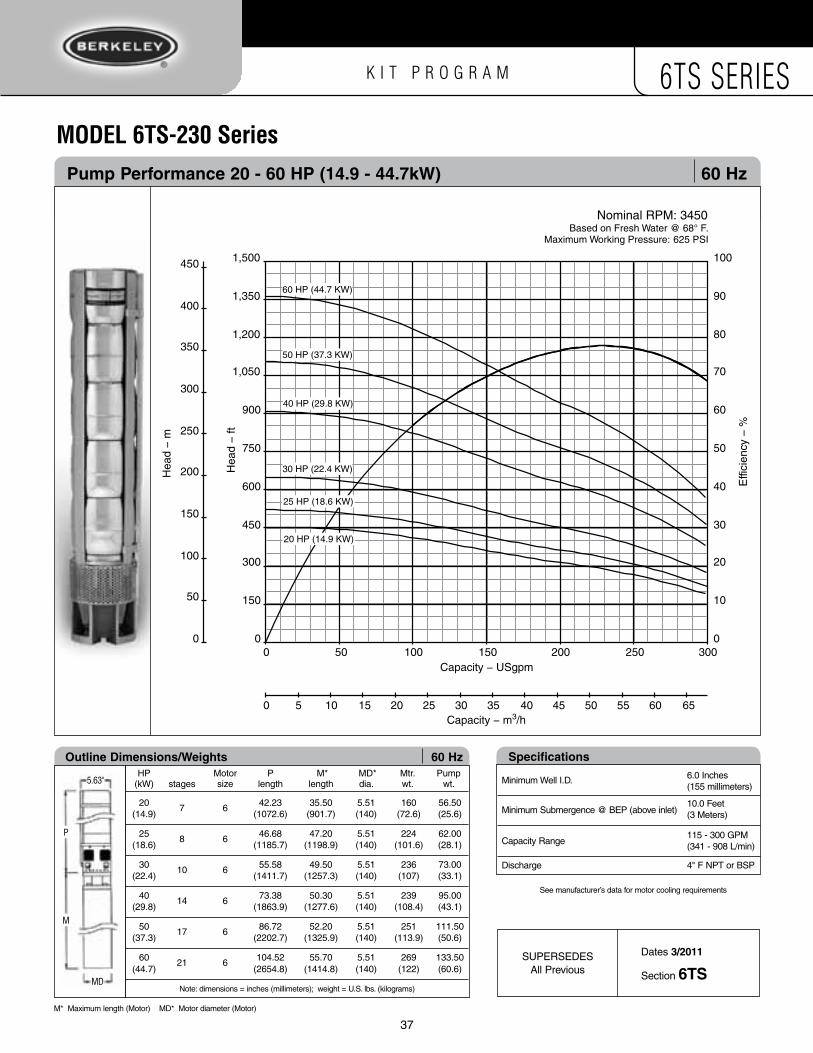
Pump Performance 20 - 60 HP (14.9 - 44.7kW) 60 Hz
mODel 6TS-230 Series
0 50 100 150 200 250 300Capacity − USgpm
0 5 10 15 20 25 30 35 40 45 50 55 60 65
0
50
100
150
200
250
300
350
400
450
Hea
d −
m
0
10
20
30
40
50
60
70
80
90
100
Effi
cien
cy −
%
0
150
300
450
600
750
900
1,050
1,200
1,350
1,500
Hea
d −
ft
Capacity − m3/h
Nominal RPM: 3450Based on Fresh Water @ 68° F.
Maximum Working Pressure: 625 PSI
30 HP (22.4 KW)
25 HP (18.6 KW)
20 HP (14.9 KW)
60 HP (44.7 KW)
40 HP (29.8 KW)
50 HP (37.3 KW)
specifications
Minimum Well I.D.
Minimum Submergence @ BEP (above inlet)
Capacity Range
Discharge
6.0 Inches (155 millimeters)
10.0 Feet (3 Meters)
115 - 300 GPM (341 - 908 L/min)
4" F NPT or BSP
See manufacturer’s data for motor cooling requirements
HP Motor P M* MD* Mtr. Pump (kW) stages size length length dia. wt. wt.
20 7 6 42.23 35.50 5.51 160 56.50 (14.9) (1072.6) (901.7) (140) (72.6) (25.6)
25 8 6 46.68 47.20 5.51 224 62.00 (18.6) (1185.7) (1198.9) (140) (101.6) (28.1)
30 10 6 55.58 49.50 5.51 236 73.00 (22.4) (1411.7) (1257.3) (140) (107) (33.1)
40 14 6 73.38 50.30 5.51 239 95.00 (29.8) (1863.9) (1277.6) (140) (108.4) (43.1)
50 17 6 86.72 52.20 5.51 251 111.50 (37.3) (2202.7) (1325.9) (140) (113.9) (50.6)
60 21 6 104.52 55.70 5.51 269 133.50 (44.7) (2654.8) (1414.8) (140) (122) (60.6)
Note: dimensions = inches (millimeters); weight = U.S. lbs. (kilograms)
outline Dimensions/Weights 60 Hz
5.63"
MD
M
P
Dates 3/2011
Section 6tsSUPERSEDES
All Previous
M* Maximum length (Motor) MD* Motor diameter (Motor)

K I T P R O G R A M 6TS SERIES
38
Pump KIt Build Chart – 230 series Mixed Flow 60 Hz60 Hz – 230 series
no. of stages 1 2 3 4 5
Horsepower 5HP 7.5HP 10HP 15HP
Kilowatts 3.7kW 5.6kW 7.5kW 11.2kW
number of KIts Required – per no. of stages
KIT 6TS-BKT4a1 1 1
KIT 6TS-BKT6b 1
KIT 6TS-230FSTG 1 1 1 1
KIT 6TS-230MIDn 1* 1 2 3 4
KIT 6TS-115-300Su 1 1 1 1
KIT 6TS-D4NPTZ1 1 1 1
KIT 6TS-D4BSP
▲▲
▲
Pump Cut-off Chart – 230 series Mixed Flow 60 Hz KIt 6ts-115-300 (short)
no. of stages 1 2 3 4 5
Kilowatts 3.7kW 5.6kW 7.5kW 11.2kW
Horsepower 5HP 7.5HP 10HP 15HP
LenGtH In InCHes (millimeters)
Shaft Cut-off10.97
(278.5)10.97
(278.5)15.41
(391.5)19.86
(504.5)24.31
(617.5)
Straps Cut-off**15.67
(398.1)15.67
(398.1)20.12
(511.1)24.57
(624.1)29.02
(737.1)
Straps Formed14.76 (375)
14.76 (375)
19.21 (488)
23.66 (601)
28.11 (714)
Cable-Guard Cut-off19.06 (484)
19.06 (484)
23.50 (597)
27.95 (710)
32.40 (823)
▲▲
▲u
* Impeller not used in one-stage pumps.**Length includes "J-bend".
note: If using the 4 x 6 suction bracket, the shaft length must be increased by 0.67 inches (17 mm).
Z1

K I T P R O G R A M 6TS SERIES
39
Pump KIt Build Chart – 230 series Mixed Flow 60 Hz60 Hz – 230 series
no. of stages 6 7 8 9 10 11 12 13 14 15 16 17 18 19 20 21
Kilowatts 14.9kW 18.6kW 22.4kW 29.8kW 37.3kW 44.7kW
Horsepower 20HP 25HP 30HP 40HP 50HP 60HP
number of KIts Required – per no. of stages
KIT 6TS-BKT6b 1 1 1 1 1 1 1
KIT 6TS-230FSTG 1 1 1 1 1 1 1
KIT 6TS-230MIDn 5 6 7 8 9 10 11 12 13 14 15 16 17 18 19 20
KIT 6TS-115-300Su 1 1
KIT 6TS-115-300MV 1 1 1 1
KIT 6TS-115-300LW 1
KIT 6TS-D4NPTZ1 1 1 1 1 1 1
KIT 6TS-D4BSP
▲▲
▲
Pump Cut-off Chart – 230 series Mixed Flow 60 Hz KIt 6ts-115-300 (short)
no. of stages 6 7 8 9 10 11 12 13 14 15 16 17
Kilowatts 14.9kW 18.6kW 22.4kW 29.8kW 37.3kW
Horsepower 20HP 25HP 30HP 40HP 50HP
LenGtH In InCHes (millimeters)
Shaft Cut-off28.76
(730.5)33.21
(843.5)37.66
(956.5)
Straps Cut-off**33.47
(850.1)37.92
(963.1)42.37
(1076.1)
Straps Formed32.56 (827)
37.01 (940)
41.46 (1053)
Cable-Guard Cut-off36.85 (936)
41.30 (1049)
45.75 (1162)
KIt 6ts-115-300 (medium)
Shaft Cut-off42.11
(1069.5)46.56
(1182.5)51.00
(1295.5)55.45
(1408.5)59.90
(1521.5)64.35
(1634.5)68.80
(1747.5)73.25
(1860.5)77.70
(1973.5)
Straps Cut-off**46.81
(1189.1)51.26
(1302.1)55.71
(1415.1)60.16
(1528.1)64.61
(1641.1)69.06
(1754.1)73.51
(1867.1)77.96
(1980.1)82.41
(2093.1)
Straps Formed45.91 (1166)
50.35 (1279)
54.80 (1392)
59.25 (1505)
63.70 (1618)
68.15 (1731)
72.60 (1844)
77.05 (1957)
81.50 (2070)
Cable-Guard Cut-off50.20 (1275)
54.65 (1388)
59.09 (1501)
63.54 (1614)
67.99 (1727)
72.44 (1840)
76.89 (1953)
81.34 (2066)
85.79 (2179)
▲▲
▲▲
KIt 6ts-115-300 (long)
no. of stages 18 19 20 21
Kilowatts 44.7kW
Horsepower 60HP
LenGtH In InCHes (millimeters)
Shaft Cut-off82.15
(2086.5)86.59
(2199.5)91.04
(2312.5)95.49
(2425.5)
Straps Cut-off**86.85
(2206.1)91.30
(2319.1)95.75
(2432.1)100.20
(2545.1)
Straps Formed85.95 (2183)
90.39 (2296)
94.84 (2409)
99.29 (2522)
Cable-Guard Cut-off90.24 (2292)
94.69 (2405)
99.13 (2518)
103.58 (2631)
▲▲
▲
u
V
W
**Length includes "J-bend".
note: If using the 4 x 6 suction bracket, the shaft length must be increased by 0.67 inches (17 mm).
Z1

40
K I T P R O G R A M 6TS SERIES
mODel 6TS-300 Series single stage Pump Performance 60 Hz
80
70
60
50
40
30
20
10
0
Hea
d −
m
Hea
d −
ft
20
15
10
5
0
Nominal RPM: 3450Based on Fresh Water @ 68° F.
Maximum Working Pressure: 650 PSI
Effi
cien
cy −
%
80
70
60
50
40
30
20
10
0
Pow
er –
kW
Pow
er –
hp
3
2
1
0
5
4
3
2
1
0
Capacity − USgpm
Capacity − m3/h
0 10 20 30 40 50 60 70 80 90 100 110
0 50 100 150 200 250 300 350 400 450 500
4.13 X 3.39 in.

K I T P R O G R A M 6TS SERIES
40 41
Pump Performance 5 - 20 HP (3.7 - 14.9kW) 60 Hz
mODel 6TS-300 Series
0 50 100 150 200 250 300 350 400 450
Capacity − USgpm
0 10 20 30 40 50 60 70 80 90 100
0
20
40
60
80
100
120
Hea
d −
m
0
10
20
30
40
50
60
70
80
90
100
Effi
cien
cy −
%
0
40
80
120
160
200
240
280
320
360
400
Hea
d −
ft
Capacity − m3/h
Nominal RPM: 3450Based on Fresh Water @ 68° F.
Maximum Working Pressure: 625 PSI
5 HP (3.7 KW)
15 HP (11.2 KW)
20 HP (14.9 KW)
10 HP (7.5 KW)
7.5 HP (5.6 KW)
specifications
Minimum Well I.D.
Minimum Submergence @ BEP (above inlet)
Capacity Range
Discharge
6.0 Inches (155 millimeters)
10.0 Feet (3 Meters)
150 - 400 GPM (454 - 1211 L/min)
4" F NPT or BSP
See manufacturer’s data for motor cooling requirements
HP Motor P M* MD* Mtr. Pump (kW) stages size length length dia. wt. wt.
1 1 4 15.65 10.66 3.75 21 24 (0.7) (397.5) (270.8) (95) (9.5) (10.9)
2 2 4 16.98 13.62 3.75 29 26 (1.5) (431.3) (345.9) (95) (13.2) (11.8)
3 3 4 18.31 20.62 3.75 44 27 (2.2) (465.1) (523.7) (95) (20) (12.2)
5 5 4 20.96 23.62 3.75 55 31 (3.7) (532.4) (599.9) (95) (24.9) (14.1)
5 5 6 20.96 27.00 5.51 95 31 (3.7) (532.4) (685.8) (140) (43.1) (14.1)
7.5 8 4 24.95 29.62 3.75 70 37 (5.6) (633.7) (752.3) (95) (31.8) (16.8)
7.5 8 6 24.95 27.60 5.51 114 37 (5.6) (633.7) (701) (140) (51.7) (16.8)
Note: dimensions = inches (millimeters); weight = U.S. lbs. (kilograms)
outline Dimensions/Weights 60 Hz
5.63"
MD
M
P
HP Motor P M* MD* Mtr. Pump (kW) stages size length length dia. wt. wt.
5 1 4 24.44 23.62 3.75 55 23.50 (3.7) (620.8) (599.9) (95) (24.9) (10.7)
5 1 6 24.44 27.00 5.51 95 23.50 (3.7) (620.8) (685.8) (140) (43.1) (10.7)
7.5 2 4 24.44 29.62 3.75 70 29.00 (5.6) (620.8) (752.3) (95) (31.8) (13.2)
7.5 2 6 19.99 27.60 5.51 114 29.00 (5.6) (507.7) (701) (140) (51.7) (13.2)
10 2 4 19.99 43.89 3.75 120 29.00 (7.5) (507.7) (1114.8) (95) (54.4) (13.2)
10 2 6 19.99 29.80 5.51 127 29.00 (7.5) (507.7) (756.9) (140) (57.7) (13.2)
15 4 6 28.89 30.40 5.51 130 40.00 (11.2) (733.8) (772.2) (140) (59.1) (18.1)
20 5 6 33.34 35.50 5.51 160 45.50 (14.9) (846.8) (901.7) (140) (72.7) (20.6)
Note: dimensions = inches (millimeters); weight = U.S. lbs. (kilograms)
outline Dimensions/Weights 60 Hz
5.63"
MD
M
P
Dates 3/2011
Section 6tsSUPERSEDES
All Previous
M* Maximum length (Motor) MD* Motor diameter (Motor)

K I T P R O G R A M 6TS SERIES
Dates 3/2011
Section 6tsSUPERSEDES
All Previous
M* Maximum length (Motor) MD* Motor diameter (Motor)
Pump Performance 25 - 60 HP (18.6 - 44.7kW) 60 Hz
mODel 6TS-300 Series
0 50 100 150 200 250 300 350 400 450Capacity − USgpm
0 10 20 30 40 50 60 70 80 90 100
0
50
100
150
200
250
300
350
400
450
Hea
d −
m
0
10
20
30
40
50
60
70
80
90
100
Effi
cien
cy −
%
0
150
300
450
600
750
900
1,050
1,200
1,350
1,500
Hea
d −
ft
Capacity − m3/h
Nominal RPM: 3450Based on Fresh Water @ 68° F.
Maximum Working Pressure: 625 PSI
30 HP (22.4 KW)
25 HP (18.6 KW)
60 HP (44.7 KW)
40 HP (29.8 KW)
50 HP (37.3 KW)
specifications
Minimum Well I.D.
Minimum Submergence @ BEP (above inlet)
Capacity Range
Discharge
6.0 Inches (155 millimeters)
10.0 Feet (3 Meters)
150 - 400 GPM (454 - 1211 L/min)
4" F NPT or BSP
See manufacturer’s data for motor cooling requirements
HP Motor P M* MD* Mtr. Pump (kW) stages size length length dia. wt. wt.
25 7 6 42.23 47.20 5.51 224 56.50 (18.6) (1072.6) (1198.9) (140) (101.6) (25.6)
30 8 6 46.68 49.50 5.51 236 62.00 (22.4) (1185.7) (1257.3) (140) (107) (28.1)
40 11 6 60.03 50.30 5.51 239 78.50 (29.8) (1524.8) (1277.6) (140) (108.4) (35.6)
50 14 6 73.38 52.20 5.51 251 95.00 (37.3) (1863.9) (1325.9) (140) (113.9) (43.1)
60 17 6 86.72 55.70 5.51 269 111.50 (44.7) (2202.7) (1414.8) (140) (122) (50.6)
Note: dimensions = inches (millimeters); weight = U.S. lbs. (kilograms)
outline Dimensions/Weights 60 Hz
5.63"
MD
M
P
42

K I T P R O G R A M 6TS SERIES
43
Pump KIt Build Chart – 300 series Mixed Flow 60 Hz60 Hz – 300 series
no. of stages 1 2 3 4 5
Kilowatts 3.7kW 7.5kW 11.2kW 14.9kW
Horsepower 5HP 10HP 15HP 20HP
number of KIts Required – per no. of stages
KIT 6TS-BKT4a1 1
KIT 6TS-BKT6b 1 1
KIT 6TS-300FSTH 1 1 1 1
KIT 6TS-300MIDP 1* 1 2 3 4
KIT 6TS-115-300Su 1 1 1 1
KIT 6TS-D4NPTZ1 1 1 1
KIT 6TS-D4BSP
▲▲
▲
Pump Cut-off Chart – 300 series Mixed Flow 60 Hz KIt 6ts-115-300 (short)
no. of stages 1 2 3 4 5
Kilowatts 3.7kW 7.5kW 11.2kW 14.9kW
Horsepower 5HP 10HP 15HP 20HP
LenGtH In InCHes (millimeters)
Shaft Cut-off10.97
(278.5)10.97
(278.5)15.41
(391.5)19.86
(504.5)24.31
(617.5)
Straps Cut-off**15.67
(398.1)15.67
(398.1)20.12
(511.1)24.57
(624.1)29.02
(737.1)
Straps Formed14.76 (375)
14.76 (375)
19.21 (488)
23.66 (601)
28.11 (714)
Cable-Guard Cut-off19.06 (484)
19.06 (484)
23.50 (597)
27.95 (710)
32.40 (823)
▲▲
▲u
* Impeller not used in one-stage pumps.**Length includes "J-bend".
note: If using the 4 x 6 suction bracket, the shaft length must be increased by 0.67 inches (17 mm).
Z1

K I T P R O G R A M 6TS SERIES
44
Pump KIt Build Chart – 300 series Mixed Flow 60 Hz60 Hz – 300 series
no. of stages 6 7 8 9 10 11 12 13 14 15 16 17
Kilowatts 18.6kW 22.4kW 29.8kW 37.3kW 44.7kW
Horsepower 25HP 30HP 40HP 50HP 60HP
number of KIts Required – per no. of stages
KIT 6TS-BKT6b 1 1 1 1 1
KIT 6TS-300FSTH 1 1 1 1 1
KIT 6TS-300MIDP 5 6 7 8 9 10 11 12 13 14 15 16
KIT 6TS-115-300Su 1 1
KIT 6TS-115-300MV 1 1 1
KIT 6TS-D4NPTZ1 1 1 1 1
KIT 6TS-D4BSP
▲▲
▲
Pump Cut-off Chart – 300 series Mixed Flow 60 Hz KIt 6ts-115-300 (short)
no. of stages 6 7 8 9 10 11 12 13 14 15 16 17
Kilowatts 18.6kW 22.4kW 29.8kW 37.3kW 44.7kW
Horsepower 25HP 30HP 40HP 50HP 60HP
LenGtH In InCHes (millimeters)
Shaft Cut-off28.76
(730.5)33.21
(843.5)37.66
(956.5)
Straps Cut-off**33.47
(850.1)37.92
(963.1)42.37
(1076.1)
Straps Formed32.56 (827)
37.01 (940)
41.46 (1053)
Cable-Guard Cut-off36.85 (936)
41.30 (1049)
45.75 (1162)
KIt 6ts-115-300 (medium)
Shaft Cut-off42.11
(1069.5)46.56
(1182.5)51.00
(1295.5)55.45
(1408.5)59.90
(1521.5)64.35
(1634.5)68.80
(1747.5)73.25
(1860.5)77.70
(1973.5)
Straps Cut-off**46.81
(1189.1)51.26
(1302.1)55.71
(1415.1)60.16
(1528.1)64.61
(1641.1)69.06
(1754.1)73.51
(1867.1)77.96
(1980.1)82.41
(2093.1)
Straps Formed45.91 (1166)
50.35 (1279)
54.80 (1392)
59.25 (1505)
63.70 (1618)
68.15 (1731)
72.60 (1844)
77.05 (1957)
81.50 (2070)
Cable-Guard Cut-off50.20 (1275)
54.65 (1388)
59.09 (1501)
63.54 (1614)
67.99 (1727)
72.44 (1840)
76.89 (1953)
81.34 (2066)
85.79 (2179)
▲▲
▲u
V
**Length includes "J-bend".
note: If using the 4 x 6 suction bracket, the shaft length must be increased by 0.67 inches (17 mm).
Z1

K I T P R O G R A M 6TS SERIES
45
aSSemblY inSTruCTiOnS – radial FlowPrior to assembly, refer to Shaft Cut-Off and Straightening instructions on page 60.
▼ ▼ ▼
▼ ▼ ▼
▼ ▼ ▼
steP 1 Pump Assembly Fixture #1A. Standard 6" NEMA Motor fit.
steP 3 Secure Suction Bracket #24 to Fixture #1A using Hex Bolts #29 and Split Washers #30. (Suction Bracket KIT).
steP 2 Assemble Suction Bracket #24 (Suction Bracket KIT) to Assembly Fixture #1A.
steP 6 Fit the First-Stage Bowl w/o Diffuser #15 (First-Stage KIT) in Suction Bracket #24.
steP 5 Slide the Inlet Shaft Spacer #16 (longest spacer – First-Stage KIT) on to the Pump Shaft so that it rests on the top of the Coupling #27. NOTE: If using 4" motor bracket (BKT4), install the 17.04mm (M14054) #16a Distance Spacer first, then the Inlet Shaft Spacer #16.
steP 7 Make sure First-Stage Bowl w/o Diffuser #15 is properly “seated” on the Suction Bracket #24.
steP 9 Insert a Stage Spacer #14 (short spacer – Intermediate KIT) on the shaft until it rests on the Impeller #13.
steP 8 Slide First-Stage Impeller #13 (Intermediate KIT) on the Shaft until seated on the Inlet Shaft Spacer #16.
▼ ▼ ▼
▼ ▼ ▼
steP 4 Ref: See page 53 for Shaft/Coupling Assembly. Clean Pump Shaft/Coupling Assembly #26, 27 and 28 (Shaft/Strap/Cable Guard KIT and Suction Bracket KIT). Insert on to Fixture #1A.

K I T P R O G R A M 6TS SERIES
46
steP 16 Fit Stack Compression Washer #5 (Suction Bracket KIT) over the Bearing Journal #6. Apply Loctite™ threadlocker ® to the Stack Compression Capscrew #4 (Suction Bracket KIT).
▼ steP 18 Fit Guide-Housing Assembly #7 (First-Stage KIT) on to the top Bowl with Diffuser #11.
▼▼ steP 17 Tighten Stack Compression Screw #4 – do not exceed 15 ft.-lbs (2.0 kgm).
aSSemblY inSTruCTiOnS – radial Flow
steP 11 Repeat Steps 8, 9 and 10 (determined by pump stage count). Rotate shaft for “free rotation” after every stage of assembly. Final Stage Spacer #14 not needed.
steP 13 Place Fiber Washer #9 (Suction Bracket KIT) on the Thrust Support Washer #10.
steP 14 Place top Stainless Washer #8 (largest ID center hole – Suction Bracket KIT) over the Fiber Washer #9.
steP 15 Place the hard chrome-plated Bearing Journal #6 (Suction Bracket KIT) inside the Stainless Washer #8 and Fiber Washer #9 until it rests on the top of the Thrust Washer #10.
▼ ▼ ▼
▼ ▼▼
steP 10 Seat the Bowl with Diffuser #11 (Intermediate-Stage KIT) on to the First-Stage Bowl w/o Diffuser #15.
steP 12 Final Top-Stage: Use Discharge Shaft Spacer #12 (First-Stage KIT) in place of extra Stage Spacer #14 from last Intermediate-Stage KIT.Insert the Thrust Support Washer #10 (smallest ID center hole – Suction Bracket KIT) on the Discharge Shaft Spacer #12.

K I T P R O G R A M 6TS SERIES
46 47
steP 26 Tighten pump Strap Capscrews #19 diagonally, using a spanner or ratchet wrench.
steP 27 (FoR ReFeRenCe onLY) Using a torque wrench, tighten Strap Capscrews #19 to 47 ft.-lbs. (6.5 kgm).
▼ ▼
aSSemblY inSTruCTiOnS – radial Flow
steP 19 Gently tap the Guide Housing Assembly #7 with a rubber mallet.
steP 20 Assemble Check Valve Flange #3 (First-Stage KIT) on to the Guide Housing Assembly #7.
steP 22 Place a Check Valve Poppet #2 (Discharge KIT) on to the Check Valve Flange #3 (if required).
steP 21 Gently tap the Check Valve Flange #3 with a rubber mallet to seat it on to the Guide Housing Assembly #7.
steP 23 Align vertically the Discharge #1 (Discharge KIT) “strap slots” with the Suction Bracket #24 “strap slots”.
Fit the Discharge #1 on to the Check Valve Flange #3 and tap it with a rubber mallet to fit correctly.
steP 25 Assemble Lock Washer #18 on to Strap Capscrew #19 (Suction Bracket KIT) through Suction Bracket #24 and pump Strap #20 and hand tighten to Strap Nut #14 as far as possible. Short side of nut goes on top.
steP 24 Ref: See page 54 for strap bending instructions. Fit Straps #20 (Shaft/Straps/Cable Guard KIT) in to the “strap slots” in the Discharge #1.
▼ ▼ ▼
▼ ▼ ▼
▼
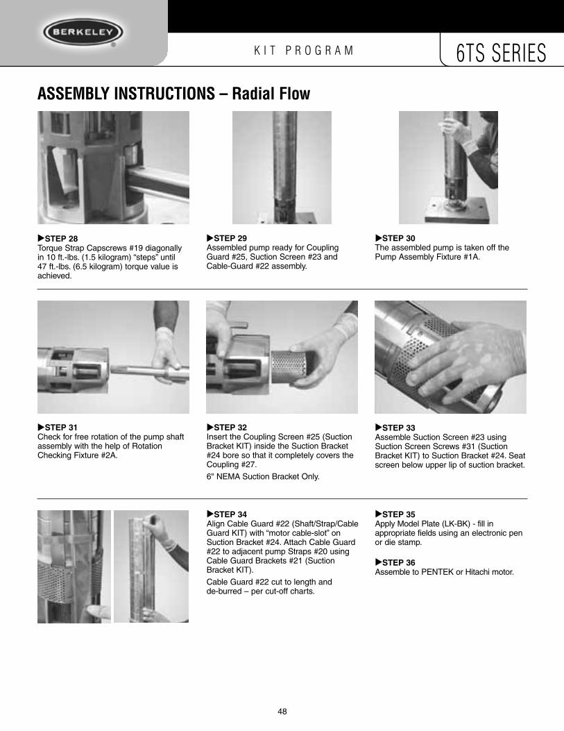
K I T P R O G R A M 6TS SERIES
48
aSSemblY inSTruCTiOnS – radial Flow
steP 28 Torque Strap Capscrews #19 diagonally in 10 ft.-lbs. (1.5 kilogram) “steps” until 47 ft.-lbs. (6.5 kilogram) torque value is achieved.
steP 29 Assembled pump ready for Coupling Guard #25, Suction Screen #23 and Cable-Guard #22 assembly.
steP 31 Check for free rotation of the pump shaft assembly with the help of Rotation Checking Fixture #2A.
steP 30 The assembled pump is taken off the Pump Assembly Fixture #1A.
steP 32 Insert the Coupling Screen #25 (Suction Bracket KIT) inside the Suction Bracket #24 bore so that it completely covers the Coupling #27.
6" NEMA Suction Bracket Only.
▼ ▼ ▼
▼ ▼ steP 33 Assemble Suction Screen #23 using Suction Screen Screws #31 (Suction Bracket KIT) to Suction Bracket #24. Seat screen below upper lip of suction bracket.
▼
steP 34 Align Cable Guard #22 (Shaft/Strap/Cable Guard KIT) with “motor cable-slot” on Suction Bracket #24. Attach Cable Guard #22 to adjacent pump Straps #20 using Cable Guard Brackets #21 (Suction Bracket KIT).
Cable Guard #22 cut to length and de-burred – per cut-off charts.
▼ steP 35 Apply Model Plate (LK-BK) - fill in appropriate fields using an electronic pen or die stamp.
steP 36 Assemble to PENTEK or Hitachi motor.
▼▼

K I T P R O G R A M 6TS SERIES
48 49
5.20 i
n.(13
2 mm)
1.75 in.(44.5 mm)
1.61 in.(40.8 mm)
1.27 in.(32.3 mm)
3.22 in.(81.8 mm)
1.50 in.(38.1 mm)
0.11 in.(2.8 mm)
5.20
in.
(132
mm
)
1.75 in.(44.5 mm)
1.61 in.(40.8 mm)
1.27 in.(32.3 mm)
2.55 in.(64.75 mm)
2.87 in.(73 mm)
0.11 in.(2.8 mm)
5.20
in.
(132
mm
)
1.75 in.(44.5 mm)
1.61 in.(40.8 mm)
1.27 in.(32.3 mm)
2.55 in.(64.75 mm)
2.87 in.(73 mm)
0.11 in.(2.8 mm)
PumP aSSemblY – radial Flow
MoDeL 6ts-70 series MoDeL 6ts-70 series 4" Motor Bracket 6" Motor Bracket

K I T P R O G R A M 6TS SERIES
50
PumP aSSemblY – radial Flow
5.20
in.
(132
mm
)
1.75 in.(44.5 mm)
1.91 in.(48.5 mm)
1.50 in.(38.1 mm)
3.29 in.(83.5 mm)
1.50 in.(38.1 mm)
0.11 in.(2.8 mm)
3 in. B.S.P. or 3 in. N.P.T.
5.20
in.
(132
mm
)
1.75 in.(44.5 mm)
1.91 in.(48.5 mm)
0.11 in.(2.8 mm)
1.50 in.(38.1 mm)
2.62 in.(66.5 mm)
2.87 in.(73 mm)
3 in. B.S.P. or 3 in. N.P.T.
MoDeL 6ts-90 series MoDeL 6ts-90 series 4" Motor Bracket 6" Motor Bracket
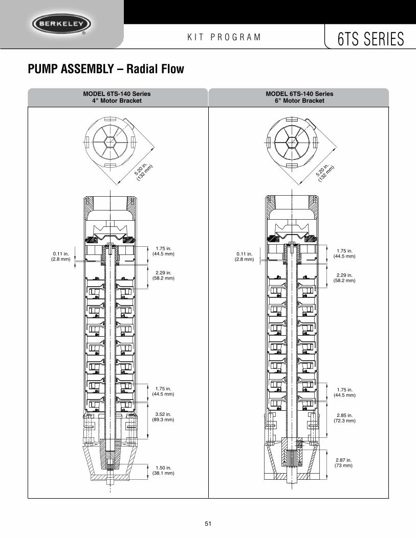
K I T P R O G R A M 6TS SERIES
50 51
PumP aSSemblY – radial Flow
5.20
in.
(132
mm
)
1.75 in.(44.5 mm)
2.29 in.(58.2 mm)
1.75 in.(44.5 mm)
3.52 in.(89.3 mm)
1.50 in.(38.1 mm)
0.11 in.(2.8 mm)
5.20
in.
(132
mm
)
1.75 in.(44.5 mm)
2.29 in.(58.2 mm)
1.75 in.(44.5 mm)
2.85 in.(72.3 mm)
2.87 in.(73 mm)
0.11 in.(2.8 mm)
MoDeL 6ts-140 series MoDeL 6ts-140 series 4" Motor Bracket 6" Motor Bracket

K I T P R O G R A M 6TS SERIES
52
▼ ▼ ▼
▼ ▼ ▼
▼ ▼ ▼ steP 9 Assemble the Distance Sleeve #11 (second longest spacer), Fiber Washer #13 and Stainless Washer #12 (largest ID center hole – First-Stage KIT) in that order, until they rest on the Thrust Support Washer #14.
aSSemblY inSTruCTiOnS – mixed FlowPrior to assembly, refer to Shaft Cut-Off and Straightening instructions on page 60.
steP 1 Pump Assembly Fixture #1A. Standard 6" NEMA Motor fit.
steP 3 Ref: See page 53 for Shaft/Coupling Assembly. Clean Pump Shaft/Coupling Assembly #27, 28, and 29 (Shaft/Strap/Cable Guard KIT and Suction Bracket KIT). Insert on to Fixture #1A.
steP 2 Assemble Suction Bracket #25 to Assembly Fixture #1A using Hex Bolts #30 and Split Washers #31 (Suction Bracket KIT).
steP 4 Slide the Inlet Shaft Spacer #19 (longest spacer in the First-Stage KIT) on to the Pump Shaft so that it rests on the top of the Coupling #28). NOTE: If using 4" motor bracket (BKT4), install 17.04mm spacer (M14054) #19a, then the Inlet Shaft Spacer #19.
steP 6 Slide First-Stage Impeller #8 (First-Stage KIT) on the Shaft until seated on the Inlet Shaft Spacer #19.
steP 5 Fit the First-Stage Adapter #20 (First-Stage KIT) in Suction Bracket #25.
steP 7 Assemble the Thrust Shaft Spacer #15 (the next shortest spacer – First-Stage KIT) on the shaft until it rests on the Impeller #8.
steP 8 Assemble the Thrust Washer #14 (smallest ID center hole – First-Stage KIT) on the Thrust Shaft Spacer #15.

K I T P R O G R A M 6TS SERIES
52 53
▼
aSSemblY inSTruCTiOnS – mixed Flow
steP 11 Gently tap the Bowl w/Diffuser #9 with the help of a rubber mallet.
steP 10 Place the Bowl w/Diffuser #9 (Intermediate-Stage KIT) over the First Stage Impeller #8.
steP 12 Slide an Impeller #8 (Intermediate-Stage KIT) over the shaft until it rests on the Distance Sleeve #11.
steP 13 Slide a Stage Spacer #10 (longest of all spacers – Intermediate-Stage KIT) to rest on the Impeller #8.
steP 16 Place the hard-chrome plated Bearing Journal #6 (comes in baggy with shaft compression set screw and washer – Suction Bracket KIT) until it rests on the top of the Discharge Shaft Spacer #7.
▼ ▼ ▼
▼
steP 14 Repeat steps 11, 12 and 13 (determined by pump stage count).
Rotate shaft for “free rotation” after every stage of assembly.
▼ ▼ steP 17 Fit Stack Compression Washer #5 (Suction Bracket KIT) over the Bearing Journal #6. Apply Loctite™ threadlocker® to the Stack Compression Capscrew #4. (Suction Bracket KIT).
steP 18 Tighten Stack Compression Screw #4. Do not exceed 15 ft.-lbs. (2.0 kgm).
▼ ▼
steP 15 Final Top-Stage use Discharge Shaft Spacer #7 (tiny spacer – First-Stage KIT) in place of extra Stage Spacer #10 from last Intermediate-Stage KIT.
Assemble the last Impeller #8 on to the shaft so that it rests on the Stage Spacer #10. Slide the Discharge Shaft Spacer #7 (First-Stage KIT) on to the top Impeller #8.

K I T P R O G R A M 6TS SERIES
54
▼ ▼ ▼ steP 26 Torque Strap Capscrews #18 diagonally in 10 ft.-lbs. (1.5 kilogram) “steps” until 47 ft.-lbs. (6.5 kilogram) torque value is achieved.
steP 27 Assembled pump ready for Coupling Guard #26. Suction Screen #24 and Cable-Guard #23 assembly.
steP 25 (FoR ReFeRenCe onLY) Using a torque wrench, tighten Strap Capscrews #18 to 47 ft.-lbs. (6.5 kgm).
▼▼
▼ ▼
▼
aSSemblY inSTruCTiOnS – mixed Flow
steP 19 Assemble the Top Bowl #3 (First-Stage KIT) over the shaft and seat it on the top Bowl w/Diffuser #9.
steP 20 Place the Check Valve Poppet #2 (Discharge KIT) on the Top Bowl #3 (if required).
steP 22 Ref: See page 54 for Strap bending. Fit Straps #21 (Shaft/Straps/Cable Guard KIT) in to the “strap slots” in the Discharge #1.
steP 23 Assemble Lock Washer #17 on the Strap Capscrew #18 (Suction Bracket KIT) through Suction Bracket #25 and pump Strap #21 and hand tighten to Strap Nut #16 as far as possible.
steP 24 Tighten the pump Strap Capscrews #18 diagonally, using a spanner or ratchet wrench.
▼
steP 21 Vertically align the Discharge #1 (Discharge KIT) “strap slots” with the Suction Bracket #25 “strap slots”.
Fit the Discharge #1 on to the Top Bowl #3 and tap it with a rubber mallet to fit properly.

K I T P R O G R A M 6TS SERIES
54 55
steP 30 Insert the Coupling Screen #26 (Suction Bracket KIT) inside the Suction Bracket #25 bore so that it completely covers the Coupling #28.
6" NEMA Suction Bracket only.
▼ ▼
▼ ▼
aSSemblY inSTruCTiOnS – mixed Flow
steP 28 The assembled pump is taken off the Pump Assembly Fixture #1A.
steP 29 Check for free rotation of the pump shaft assembly with the help of Rotation Checking Fixture #2A.
steP 32 Align Cable Guard #23 (Shaft/Strap/ Cable Guard KIT) with “motor cable-slot” on Suction Bracket #25. Attach Cable Guard #23 to adjacent pump Straps #21 using Cable Guard Brackets #22 (Suction Bracket KIT).Cable Guard #23 cut to length and de-burred per cut-off charts.
steP 31 Assemble Suction Screen #24 using Suction Screen Screws #32 (Suction Bracket KIT) to Suction Bracket #25.
▼▼
steP 33 Apply Model Plate (LK-BK) – fill in appropriate fields using an electronic pen or die stamp. steP 34 Assemble to PENTEK or Hitachi motor.
▼

K I T P R O G R A M 6TS SERIES
56
PumP aSSemblY – mixed Flow
5.20 i
n.(13
2 mm)
1.75 in.(44.5 mm)
0.62 in.(15.7 mm)
4.37 in.(111 mm)
2.90 in.(73.6 mm)
3.74 in.(95 mm)
1.50 in.(38.1 mm)
1.36 in.(34.4)
0.10 in.(2.5 mm)
1.22 in.(31 mm)
5.20
in.
(132
mm
)
1.75 in.(44.5 mm)
0.62 in.(15.7 mm)
4.37 in.(111 mm)
2.90 in.(73.6 mm)
3.07 in.(77.95 mm)
2.87 in.(73 mm)
1.36 in.(34.4)
0.10 in.(2.5 mm)
5.20
in.
(132
mm
)
1.75 in.(44.5 mm)
0.62 in.(15.7 mm)
4.37 in.(111 mm)
2.90 in.(73.6 mm)
3.07 in.(77.95 mm)
2.87 in.(73 mm)
1.36 in.(34.4)
0.10 in.(2.5 mm)
MoDeL 6ts-115 series MoDeL 6ts-115 series 4" Motor Bracket 6" Motor Bracket
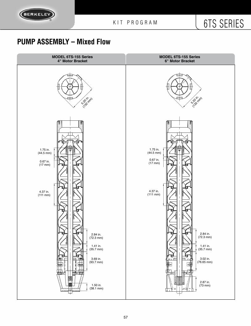
K I T P R O G R A M 6TS SERIES
57
PumP aSSemblY – mixed Flow
5.20 i
n.(13
2 mm)
1.75 in.(44.5 mm)
0.67 in.(17 mm)
4.37 in.(111 mm)
2.84 in.(72.3 mm)
1.50 in.(38.1 mm)
3.69 in.(93.7 mm)
1.41 in.(35.7 mm)
5.20 i
n.(13
2 mm)
1.75 in.(44.5 mm)
0.67 in.(17 mm)
4.37 in.(111 mm)
2.84 in.(72.3 mm)
1.50 in.(38.1 mm)
3.69 in.(93.7 mm)
1.41 in.(35.7 mm)
5.20
in.
(132
mm
)
1.75 in.(44.5 mm)
0.67 in.(17 mm)
4.37 in.(111 mm)
2.84 in.(72.3 mm)
2.87 in.(73 mm)
3.02 in.(76.65 mm)
1.41 in.(35.7 mm)
5.20
in.
(132
mm
)
1.75 in.(44.5 mm)
0.67 in.(17 mm)
4.37 in.(111 mm)
2.84 in.(72.3 mm)
2.87 in.(73 mm)
3.02 in.(76.65 mm)
1.41 in.(35.7 mm)
MoDeL 6ts-155 series MoDeL 6ts-155 series 4" Motor Bracket 6" Motor Bracket

K I T P R O G R A M 6TS SERIES
58
PumP aSSemblY – mixed Flow
5.64 i
n.
(143.2
mm)
0.58 in.(14.7 mm)
4.37 in.(111 mm)
2.96 in.(75.1 mm) 0.10 in.
(2.5 mm)
1.75 in.(44.5 mm)
1.50 in.(38.1 mm)
3.79 in.(96.2 mm)
1.30 in.(32.9 mm)
5.64 i
n.
(143.2
mm)
0.58 in.(14.7 mm)
4.37 in.(111 mm)
2.96 in.(75.1 mm) 0.10 in.
(2.5 mm)
1.75 in.(44.5 mm)
1.50 in.(38.1 mm)
3.79 in.(96.2 mm)
1.30 in.(32.9 mm)
5.64
in.
(143
.2 m
m)
0.58 in.(14.7 mm)
4.37 in.(111 mm)
2.96 in.(75.1 mm)
1.22 in.(31 mm)
0.10 in.(2.5 mm)
33.34 in.(846.8 mm)
1.75 in.(44.5 mm)
2.87 in.(73 mm)
3.12 in.(79.24 mm)
1.30 in.(32.9 mm)
5.64
in.
(143
.2 m
m)
0.58 in.(14.7 mm)
4.37 in.(111 mm)
2.96 in.(75.1 mm)
1.22 in.(31 mm)
0.10 in.(2.5 mm)
33.34 in.(846.8 mm)
1.75 in.(44.5 mm)
2.87 in.(73 mm)
3.12 in.(79.24 mm)
1.30 in.(32.9 mm)
MoDeL 6ts-230 series MoDeL 6ts-230 series 4" Motor Bracket 6" Motor Bracket

K I T P R O G R A M 6TS SERIES
58 59
PumP aSSemblY – mixed Flow
5.64 i
n.
(143.2
mm)
4.37 in.(111 mm)
0.10 in.(2.5 mm)
3.39 in.(86.2 mm)
0.40 in.(10.2 mm)
1.75 in.(44.5 mm)
1.50 in.(38.1 mm)
3.97 in.(100.8 mm)
0.86 in.(21.9 mm)
5.64 i
n.
(143.2
mm)
4.37 in.(111 mm)
0.10 in.(2.5 mm)
3.39 in.(86.2 mm)
0.40 in.(10.2 mm)
1.75 in.(44.5 mm)
1.50 in.(38.1 mm)
3.97 in.(100.8 mm)
0.86 in.(21.9 mm)
5.64
in.
(143
.2 m
m)
4.37 in.(111 mm)
0.10 in.(2.5 mm)
3.39 in.(86.2 mm)
0.40 in.(10.2 mm)
1.75 in.(44.5 mm)
2.87 in.(73 mm)
3.30 in.(83.75 mm)
0.86 in.(21.9 mm)
5.64
in.
(143
.2 m
m)
4.37 in.(111 mm)
0.10 in.(2.5 mm)
3.39 in.(86.2 mm)
0.40 in.(10.2 mm)
1.75 in.(44.5 mm)
2.87 in.(73 mm)
3.30 in.(83.75 mm)
0.86 in.(21.9 mm)
MoDeL 6ts-300 series MoDeL 6ts-300 series 4" Motor Bracket 6" Motor Bracket

K I T P R O G R A M 6TS SERIES
60
▼
▼ ▼
▼
▼ ▼ ▼ steP 7 Install one coupling set-screw. Set screw is .12" ( 3mm).NOTE: Will need metric Allen wrench.
steP 8 Using a .22" (5.5mm) drill, counter-sink the shaft. Repeat steps 7 and 8 for the other coupling set-screws.
aSSemblY inSTruCTiOnS – Shaft
Shafts supplied in Shaft/Strap/Cable-Guard – R, S, T, U, V and W KITS are supplied with one end de-burred, drilled and tapped; .31" (8 mm) dia., 1-1/4" (31.75) deep.
steP 1 Measure and cut shaft to “shaft cut-off” length, determined by pump series and pump stage count.Reference the Pump Cut-off Chart data.
steP 3 Straighten the entire length of shaft, using Shaft Straightening Fixture Kit #5A, on a 2-ton, 1-meter deck arbor press.
steP 4 Straighten the entire length of shaft until TIR is .002" to .004" (50 to 100 microns).
steP 6 Insert shaft into coupling until shaft rests on Shaft Coupling Fixture #6A.
steP 5 Assemble Shaft Coupling on Shaft Coupling Fixture #6A.
▼
steP 2 Clean shaft to remove oil and contaminates.
▼ ▼ steP 9 Lock the Coupling to the Pump Shaft with both coupling set-screws and remove from Shaft Coupling Fixture #6A and assemble to pump.
steP 10 With Suction Bracket assembled to Assembly Fixture #1A, insert shaft coupling assembly on to Fixture #1A shaft spline.

K I T P R O G R A M 6TS SERIES
60 61
aSSemblY inSTruCTiOnS – StrapTo form l-bend:
▼ steP 1 Install bender on end of a sturdy table.
▼ steP 2 Strap hole drilled or punched. Cut straps to length according to cut-off charts. De-burr. Mark position of hole according to drawings at bottom of page 62. Center punch and drill starting with 1/8" pilot hole.
▼ steP 3 Insert L-bend die into bender. Adjust fixture to be one strap width from L-bend die.
▼ steP 4 Insert strap into bender. Insert L-bend die as shown.
▼ steP 5 Place gauge measuring die over straight end of strap with hole already drilled. Be sure that "L" side of die is facing down. NOTE: If using a factory-supplied strap from SSCG Kit, make sure J-bend on strap is facing up.
▼ steP 6 Tighten the cap screw provided on the top of fixture. Use 5/16" Allen wrench to tighten die.
▼ steP 6a Strap "L" bending in progress. Form initial bend, then repeat once again to set the bend. Double check to assure a full 90˚ "L" is made.
▼ steP 7 Strap "L" bend formed.
▼ steP 7a Using a straight edge, check that strap is straight. Make necessary adjustments.Check the formed end with Strap nut and M12 Cap Screw.
L-bend die
Strap
Gauge measuring die
L-bend die

K I T P R O G R A M 6TS SERIES
62
aSSemblY inSTruCTiOnS – StrapTo form J-bend:
▼ steP 1 Insert L-bend die into bender. Adjust fixture to be one strap width from L-bend die.
▼ steP 2 Insert strap into bender. Insert L-bend die as shown.
▼ steP 3 Place gauge measuring die over undrilled end of strap. Be sure that "J" side of die is facing down.
▼ steP 4 Form initial L-bend.
▼ steP 5 Replace L-bend die with J-bend die and adjust fixture using gauge measuring die to be 3/8".
▼ steP 6 Insert J-bend die over strap with partially bent strap.
▼ ▼ steP 7 Tighten the capscrew on top of fixture. Use 5/16" Allen wrench to tighten die.
steP 8 Form initial J-bend.
▼ steP 9 Back both adjusting nuts off, one full turn each, and complete J-bend.
.500
.375
.50
.500
.375
.50
3/24/2011CAMERON500000036269B
.26 6.5
.62 15.8
"A"
Gauge measuring die
L-bend dieL-bend die
Strap
Adjusting nut
Adjusting nut (obscured)
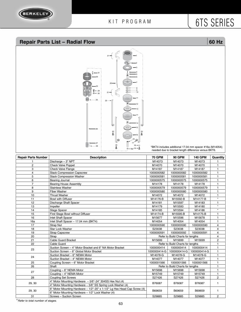
K I T P R O G R A M 6TS SERIES
62 63
Repair Parts List – Radial Flow 60 Hz
3
1718
19
25 20
28
27
26
6
54
22 7
2
1
89
21
21
16
11
11
13
12
13
15
14
10
5021 0505
24
23
31
29
30
16a*
Repair Parts number Description 70 GPM 90 GPM 140 GPM Quantity1 Discharge – 3" NPT M14073 M14073 M14073 12 Check Valve Poppet M14070 M14070 M14070 13 Check Valve Flange M14187 M14187 M14187 14 Stack Compression Capscrew 1000000582 1000000582 1000000582 15 Stack Compression Washer 1000000581 1000000581 1000000581 16 Bearing Journal 1000000575 1000000575 1000000575 17 Bearing House Assembly M14178 M14178 M14178 18 Stainless Washer 1000000579 1000000579 1000000579 19 Fiber Washer 1000000580 1000000580 1000000580 110 Thrust Washer M14072 M14072 M14072 111 Bowl with Diffuser M14176-B M15592-B M14177-B *12 Discharge Shaft Spacer M14181 M15597 M14183 113 Impeller M14179 M15593 M14180 *14 Stage Spacer M14185 M15594 M14186 *15 First Stage Bowl without Diffuser M14174-B M15595-B M14175-B 116 Inlet Shaft Spacer M15677 M15596 M15678 116a Inlet Shaft Spacer – 17.04 mm (BKT4) M14054 M14054 M14054 117 Strap Nut 1000000590 1000000590 1000000590 418 Star Lock Washer S23038 S23038 S23038 419 Strap Capscrew 1000000591 1000000592 1000000591 420 Strap Refer to Build Charts for lengths 421 Cable Guard Bracket M15699 M15699 M15699 222 Cable Guard Refer to Build Charts for lengths 1
23Suction Screen – 4" Motor Bracket and 6" NA Motor Bracket 1000000414 1000000414 1000000414 1Suction Screen – 6" Global Motor Bracket 1000000414-G 1000000414-G 1000000414-G 1
24Suction Bracket – 6" NEMA Motor M14078-G M14078-G M14078-G 1Suction Bracket – 4" NEMA Motor M14077 M14077 M14077 1
25 Coupling Screen – 6" Motor Bracket 1000001566 1000001566 1000001566 126 Shaft Refer to Build Charts for lengths 1
27Coupling – 6" NEMA Motor M15698 M15698 M15698 1Coupling – 4" NEMA Motor M15749 M15749 M15749 1
28 Coupling Set Screws S27426 S27426 S27426 2
29, 304" Motor Mounting Hardware – 5/6"-24" 304SS Hex Nut (4)
B76087 B76087 B76087 14" Motor Mounting Hardware – 5/6" SS Spring Lock Washer (4)
29, 306" Motor Mounting Hardware – 1/2"-20" x 1-1/2" Lg Hex Head Cap Screw (4)
B69659 B69659 B69659 1 6" Motor Mounting Hardware – 1/2" Lock Washer (4)
31 Screws – Suction Screen S29885 S29885 S29885 2
* Refer to total number of stages.
* BKT4 includes additional 17.04 mm spacer #16a (M14054); needed due to bracket length difference versus BKT6.
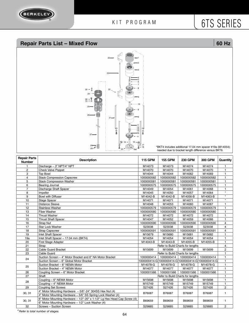
K I T P R O G R A M 6TS SERIES
64
Repair Parts List – Mixed Flow 60 Hz
1
25
26
27
29
28
3
2
22
67
22
23
19a*
9
9
11
15
16
1718
21
20
24
121314
10
54
8
8
19
8
5020 0505
3031
32
Repair Parts number
Description 115 GPM 155 GPM 230 GPM 300 GPM Quantity
1 Discharge – 3" NPT/4" NPT M14073 M14073 M14074 M14074 12 Check Valve Poppet M14070 M14070 M14070 M14070 13 Top Bowl M14044 M14044 M14062 M14069 14 Stack Compression Capscrew 1000000582 1000000582 1000000582 1000000582 15 Stack Compression Washer 1000000581 1000000581 1000000581 1000000581 16 Bearing Journal 1000000575 1000000575 1000000575 1000000575 17 Discharge Shaft Spacer M14049 M14054 M14061 M14068 18 Impeller M14045 M14050 M14057 M14064 *9 Bowl with Diffuser M14042-B M14042-B M14056-B M14063-B *10 Stage Spacer M14071 M14071 M14071 M14071 *11 Distance Sleeve M14048 M14053 M14060 M14067 112 Stainless Washer 1000000579 1000000579 1000000579 1000000579 113 Fiber Washer 1000000580 1000000580 1000000580 1000000580 114 Thrust Washer M14072 M14072 M14072 M14072 115 Thrust Shaft Spacer M14047 M14052 M14059 M14066 116 Strap Nut 1000000590 1000000590 1000000590 1000000590 417 Star Lock Washer S23038 S23038 S23038 S23038 418 Strap Capscrew 1000000591 1000000591 1000000591 1000000591 419 Inlet Shaft Spacer M15679 M15680 M15681 M15682 119a Inlet Shaft Spacer – 17.04 mm (BKT4) M14054 M14054 M14054 M14054 120 First Stage Adapter M14043-B M14043-B M14055-B M14055-B 121 Strap Refer to Build Charts for lengths 422 Cable Guard Bracket M15699 M15699 M15699 M15699 223 Cable Guard Refer to Build Charts for lengths 1
24Suction Screen – 4" Motor Bracket and 6" NA Motor Bracket 1000000414 1000000414 1000000414 1000000414 1Suction Screen – 6" Global Motor Bracket 1000000414-G 1000000414-G 1000000414-G 1000000414-G 1
25Suction Bracket – 6" NEMA Motor M14078-G M14078-G M14078-G M14078-G 1Suction Bracket – 4" NEMA Motor M14077 M14077 M14077 M14077 1
26 Coupling Screen – 6" Motor Bracket 1000001566 1000001566 1000001566 1000001566 127 Shaft Refer to Build Charts for lengths 1
28Coupling – 6" NEMA Motor M15698 M15698 M15698 M15698 1Coupling – 4" NEMA Motor M15749 M15749 M15749 M15749 1
29 Coupling Set Screws S27426 S27426 S27426 S27426 2
30, 314" Motor Mounting Hardware – 5/6"-24" 304SS Hex Nut (4)
B76087 B76087 B76087 B76087 14" Motor Mounting Hardware – 5/6" SS Spring Lock Washer (4)
30, 316" Motor Mounting Hardware – 1/2"-20" x 1-1/2" Lg Hex Head Cap Screw (4)
B69659 B69659 B69659 B69659 16" Motor Mounting Hardware – 1/2" Lock Washer (4)
32 Screws – Suction Screen S29885 S29885 S29885 S29885 2
* Refer to total number of stages.
* BKT4 includes additional 17.04 mm spacer #19a (M14054); needed due to bracket length difference versus BKT6.

K I T P R O G R A M 6TS SERIES
64 65

K I T P R O G R A M 6TS SERIES
66

K I T P R O G R A M 6TS SERIES
66 67

K I T P R O G R A M 6TS SERIES
B10117BK (11/18/11)
293 Wright Street Delavan, WI 53115 Phone: 1-888-BERKELEY Fax: 1-800-321-7893 www.berkeleypumps.com