6lgh %hdulqjv - miner enterprises€¦ · · 2012-04-05this convenient installation and...
TRANSCRIPT

Brake Beams
Side Bearings
Draft Gears
INSTALLATION AND INSPECTION GUIDEINSTALLATION AND INSPECTION GUIDE
1-630-232-3000 VERSION 6 3/2012
Perfecting Railcar Performance

TABLE OF CONTENTSOverviewIntroduction ....................................................................................................... 2List of Illustrations ............................................................................................ 2
TecsPak® Constant Contact Side BearingsGeneral Description .......................................................................................... 4Product Identification........................................................................................ 5Shelf Life ............................................................................................................9Installation
Set Up Height ........................................................................................... 10Car Body Wear Plate ................................................................................ 12Side Bearing Installation – Bolt-on Style ................................................. 13Standard Travel Retrofit Installation......................................................... 14Long Travel Retrofit Selection Guide ........................................................ 15Long Travel Retrofit Installation ................................................................ 16TecsPak® Pads............................................................................................ 20
InspectionSet Up Height ............................................................................................ 21Field or Yard Inspection............................................................................. 21Shop or Repair Track Inspection ............................................................... 23General....................................................................................................... 25Top Cap Wear Indicators ........................................................................... 25TecsPak® Pad Free Height Measurement................................................. 26
Draft GearsGeneral Description ........................................................................................ 28Procedure for Determining Serviceability
of Miner Draft Gears ................................................................................. 29
Brake BeamsGeneral Description ........................................................................................ 32Inspection........................................................................................................ 32Strut Hand Change Procedure........................................................................ 33

2
OVERVIEW
INTRODUCTION
This convenient Installation and Inspection Guide provides important technical information regardingMiner’s full-line of TecsPak® constant contact side bearings, draft gears and brake beams. In it youwill find sections covering product identification, installation, and inspection.
LIST OF ILLUSTRATIONS
TecsPak® Constant Contact (TCC) Side Bearings
Fig. 1 TCC Style ............................................................................................................................................. 5Fig. 2 TCC-II.................................................................................................................................................... 5Fig. 3 TCC-III ST ............................................................................................................................................ 5Fig. 4 TCC-III RA............................................................................................................................................. 5Fig. 5 TCC-III LT .............................................................................................................................................. 6Fig. 6 TCC-IV LT ............................................................................................................................................. 6Fig. 7 TCC-8000 RL........................................................................................................................................ 6Fig. 8 TCC-8000 RS.........................................................................................................................................6Fig. 9 TCC-4500 RA ....................................................................................................................................... 7Fig. 10 TCC-45 LTR........................................................................................................................................... 7Fig. 11 TCC-60 LTR........................................................................................................................................... 7Fig. 12 TCC-45 LTRB ........................................................................................................................................ 7Fig. 13 TCC-45 LTLP......................................................................................................................................... 8Fig. 14 TCC-45 LTLP-B ..................................................................................................................................... 8Fig. 15 Caliper Measurement....................................................................................................................... 10Fig. 16 Block Style Retrofit Set Up Height (LTLP, LTLP-B, LTRB) ................................................................ 10 Fig. 17 Block Style Retrofit Set Up Height Gage........................................................................................ 11Fig. 18 TCC-45/60 LTR Solid Stop Installation............................................................................................ 16Fig. 19 TCC-45 LTLP Pocket Installation ...................................................................................................... 17Fig. 20 TCC-45 LTLP-B .................................................................................................................................. 17Fig. 21 TCC-45 LTRB Housing Securement ................................................................................................. 18Fig. 22 Welding Procedure – Cross Section ............................................................................................... 19Fig. 23 Pocket Size Adjustment.................................................................................................................... 20

3
TecsPak® Constant Contact (TCC) Side Bearings (con’t.)
Fig. 24 Standard Set Up Height Indicators – Inspection ........................................................................... 24Fig. 25 Block Style Retrofit Set Up Height Indicators – Inspection............................................................... 24Fig. 26 TCC-IV Wear Indicator...................................................................................................................... 25Fig. 27 TCC-45/60 LTR & LTRB Wear Indicator........................................................................................... 25Fig. 28 TCC-45 LTLP-B Wear Indicator......................................................................................................... 25Fig. 29 TCC-45 LTLP Wear Indicator ............................................................................................................ 25Fig. 30 TecsPak® Pad Free Height Measurement...................................................................................... 26
Draft Gears
Fig. 31 Crown SE™ and Crown SG™ In-Car Inspection............................................................................... 29Fig. 32 Crown SE™ and Crown SG™ Out-of-Car Inspection ........................................................................ 29Fig. 33 TF-880™ In-Car Inspection................................................................................................................. 30Fig. 34 TF-880™ Out-of-Car Inspection ........................................................................................................ 30Fig. 35 SL-76™ In-Car Inspection ................................................................................................................. 31Fig. 36 SL-76™ Out-of-Car Inspection .......................................................................................................... 31
Brake Beams
Fig. 37 Miner Series 2008™ Brake Beam - #18........................................................................................... 32Fig. 38 Miner Series 2008™ Brake Beam - #24........................................................................................... 32Fig. 39 Miner Series 2008™ Brake Beam Strut Change ............................................................................ 33
Brake Beams
Side Bearings
Draft Gears
INSTALLATION AND INSPECTION GUIDEINSTALLATION AND INSPECTION GUIDE
1-630-232-3000 VERSION 6
Perfecting Railcar Performance

TECS PAK CONSTANT CONTACT (TCC) SIDE BEARINGS
GENERAL DESCRIPTION
Miner’s TecsPak® constant contact side bearings feature a unique metal-on-metal design enablingthem to provide a more stable ride by instantaneously counteracting the rotational motion of truckhunting. Their superior design breaks friction and dissipates energy before truck hunting impacts carstability and component wear. When installing and/or inspecting any of Miner’s side bearings, it iscritical to identify the proper bearing and its components. Miner side bearings include: TCC, TCC-II,TCC-III, TCC-IV and Retrofit models. Please refer to the Product Identification section (Page 5) beforeany installation and/or inspection procedures.
Miner’s TecsPak® constant contact side bearings are available in a range of preloads and designs.The model name will designate the side bearing preload in pounds (e.g. TCC-8000) or hundreds of pounds(e.g. TCC-IV-60 LT). Some models are also available in:
Standard Travel 5/16” travel from 5-1/16” set up heightRoller Assist 5/16” travel from 5-1/16” set up heightLong Travel 5/8” travel from 5-1/16” set up height
The first generation of Miner TCC side bearings, TCC-2600, -4500 and -8000, are Standard Travel (ST).The TCC-4500 RA is a Roller Assist model.
The second generation of bearings, TCC-II-25, -35, -60 and -80S, are all Long Travel (LT).
The third generation of bearings, TCC-III-30, -45, -60 and -80, are available as either Standard Travel (ST),Long Travel (LT) or Roller Assist (RA) models.
The fourth generation of bearings, TCC-IV-30, -45, -60 and -80, are all Long Travel (LT).
The TCC-8000 RS retrofit bearings are designed to fit into a single roller cage and are Standard Travel (ST).
The TCC-45 LTR and TCC-60 LTR are designed to fit into a double roller cage and are Long Travel (LT).
The TCC-45 LTLP is designed to fit into a low profile small pocket and the TCC-45 LTLP-B is designed to fit into alarge pocket low profile block style side bearing pocket and are both Long Travel (LT).
The TCC-45 LTRB is designed to fit into a standard height block style side bearing pocket and is Long Travel (LT).
®
4

PRODUCT IDENTIFICATION
Fig. 1 TCC StyleStandard Travel
MODEL TOP CAP ASSY. HOUSINGTCC-2600* 29127 29130TCC-4500 29126 29129TCC-8000 29125 29128
* No longer in production. Replace with TCC-III-30 ST on both sides of axle.
TOP CAP ASSY.
HOUSING
Fig. 2 TCC-II*Long Travel
MODEL REPLACE WITH:TCC-II-25 TCC-III-30 LT on both sides of axleTCC-II-35 TCC-III-45 LT on both sides of axleTCC-II-60 TCC-III-60 LT on both sides of axleTCC-II-80S TCC-III-80 LT on both sides of axle
*No longer in production.
5
TOP CAP(40136)
PAD
HOUSING
ROLLER(29792)
BASE PLATE(29794)
MODEL HOUSING PADTCC-III-30 RA 40318 T-0305TCC-III-45 RA 40319 T-0300TCC-III-60 RA 40320 T-0306TCC-III-80 RA 40321 T-0307
Fig. 4 TCC-III RARoller AssistStandard Travel
TOP CAP(40136)
PAD
HOUSING
Fig. 3 TCC-III STStandard Travel
MODEL HOUSING PADTCC-III-30 ST 40137 T-0305TCC-III-45 ST 40138 T-0300TCC-III-60 ST 40139 T-0306TCC-III-80 ST 40140 T-0307

Fig. 6 TCC-IV LTLong Travel
MODEL HOUSING PADTCC-IV-30 LT 40141 T-0432 (Green Insulator)TCC-IV-45 LT 40142 T-0430 (Red Insulator)TCC-IV-60 LT 40143 T-0431 (Blue Insulator)TCC-IV-80 LT 40144 T-0434 (Grey Insulator)
TOP CAP(40482)
PAD
HOUSING
6
Fig. 5 TCC-III LTLong Travel
MODEL HOUSING PADTCC-III-30 LT 40141 T-0305TCC-III-45 LT 40142 T-0300TCC-III-60 LT 40143 T-0306TCC-III-80 LT 40144 T-0307
TOP CAP(40136)
PAD
HOUSING
Fig. 7 TCC-8000 RL*Standard Travel
TOP CAP ASSY.(29125)
OVER-SOLID STOP(D-11994)
SHIM1/16” Shim (D-11999)1/8” Shim (D-11998)
* No longer in production.Replace with TCC-60 LTR.
Fig. 8 TCC-8000 RS*Standard Travel
TOP CAP ASSY.(29125)
OVER-SOLID STOP(D-11997)
SHIM1/16” Shim (D-11999)1/8” Shim (D-11998)
* No longer in production. Contact customer service for replacement recommendations
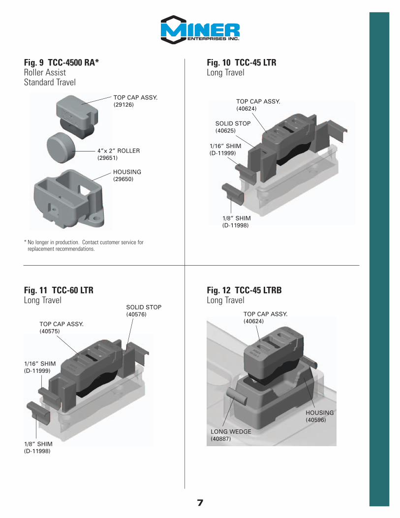
Fig. 10 TCC-45 LTRLong Travel
TOP CAP ASSY.(40624)
SOLID STOP(40625)
1/8” SHIM(D-11998)
1/16” SHIM(D-11999)
Fig. 11 TCC-60 LTRLong Travel
TOP CAP ASSY.(40575)
SOLID STOP(40576)
1/16” SHIM(D-11999)
1/8” SHIM(D-11998)
7
Fig. 9 TCC-4500 RA*Roller AssistStandard Travel
* No longer in production. Contact customer service for replacement recommendations.
TOP CAP ASSY.(29126)
4”x 2” ROLLER(29651)
HOUSING(29650)
Fig. 12 TCC-45 LTRBLong Travel
TOP CAP ASSY.(40624)
HOUSING(40596)
LONG WEDGE(40887)

8
Fig. 13 TCC-45 LTLPLong Travel
TOP CAP ASSY.(40570)
SMALL WEDGE(40672)
HOUSING(40569)
TOP CAP ASSY.(40865)
HOUSING(40864)
LONG WEDGE(40887)
Fig. 14 TCC-45 LTLP-B

SHELF LIFE
The recommended shelf life for Miner TecsPak pads is 5 years from the date of manufacture.
There is an alpha-numeric code on the outside of a TecsPak pad that can be used to determine thedate it was produced. The first 5 digits are the ones that interpret the date manufactured.
EExxaammppllee::1st five digits on TecsPak pad: 07 02507 = 2007025 = the 25th day of the year, January 25th.
The rest of the numbers are for Miner’s internal tracking.
Occasionally, the first zero was left off. So the date code might look like this;7025
This is still the same as above.
In most cases, the pad will need to be cleaned to see the date code. Sometimes just simplywiping it with your hands is fine and other times you may need some water to wash off the dustand dirt.
9

CAR BODY WEAR PLATE
INSTALLATION
SET UP HEIGHTThe set up height, or the vertical distance between the car body side bearing wear plate and thehousing mounting surface, should be measured using inside calipers and a steel rule. A twelve-inch steel straightedge is helpful for checking the flatness of the body wear plate and the bolstermounting surface.
Standard Set Up Height
Fig. 15 Caliper Measurement
Models Installation or Adjustment*^
TCC, TCC II, TCC III,TCC IV, TCC 45/60 LTR
Metal Liner New Non-Metallic Liner or Lube Disc
Nominal Tolerance Nominal Tolerance5-1/16 ± 1/16 5-1/8 ± 1/16
Range Max: 5-1/8 Max: 5-3/16Min: 5 Min: 5-1/16
Nominal ToleranceNominalTolerance5/8 +/-1/1611/16+/-1/16Max: 11/16Max:3/4Min: 9/16Min:5/8*Installation and adjustment should be done in empty condition on level track^Male end of articulated connected cars may have a nominal value of 5-3/16RangeRangeTCC 45 LTLP,TCC 45 LTLP-BTCC, TCC II, TCC III,TCC IV, TCC 45/60 LTR,TCC 45 LTRBMetal Liner New Non-Metallic Liner orLube DiscModels Installation or Adjustment*^Metal Liner New Non-Metallic Liner orLube Disc
Models Installation or Adjustment
TCC 45 LTLP,TCC 45 LTLP-BTCC 45 LTRB
Metal Liner New Non-Metallic Liner or Lube Disc
Nominal Tolerance Nominal Tolerance5/8 ± 1/16 11/16 ± 1/16
Range Max: 11/16 Max: 3/4Min: 9/16 Min: 5/8
* Installation and adjustment should be done in empty condition on level track^ Male end of articulated connected cars may have a nominal value of 5-3/16
Alternative Set Up HeightMiner side bearings allow greater flexibility in the set up height. On some articulated intermodalcars, at the male location of the articulated connection, the side bearing can have a set up heightof 5-3/16”, ± 1/16”. On selected autorack cars, the long travel side bearing can have a set upheight of 5-1/16”, ± 1/8”. (Refer to owners’ instructions, or stenciling, on these types of cars.)If a new elastomeric horizontal center bowl liner is used, it is recommended that you add 1/16” tothe nominal dimension.
Fig. 16 Block Style Retrofit Set Up Height
Models Installation or Adjustment*^
TCC, TCC II, TCC III,TCC IV, TCC 45/60 LTR
Metal Liner New Non-Metallic Liner or Lube Disc
Nominal Tolerance Nominal Tolerance5-1/16 ± 1/16 5-1/8 ± 1/16
Range Max: 5-1/8 Max: 5-3/16Min: 5 Min: 5-1/16
Nominal ToleranceNominalTolerance5/8 +/-1/1611/16+/-1/16Max: 11/16Max:3/4Min: 9/16Min:5/8*Installation and adjustment should be done in empty condition on level track^Male end of articulated connected cars may have a nominal value of 5-3/16RangeRangeTCC 45 LTLP,TCC 45 LTLP-BTCC, TCC II, TCC III,TCC IV, TCC 45/60 LTR,TCC 45 LTRBMetal Liner New Non-Metallic Liner orLube DiscModels Installation or Adjustment*^Metal Liner New Non-Metallic Liner orLube Disc
Models Installation or Adjustment
TCC 45 LTLP,TCC 45 LTLP-BTCC 45 LTRB
Metal Liner New Non-Metallic Liner or Lube Disc
Nominal Tolerance Nominal Tolerance5/8 ± 1/16 11/16 ± 1/16
Range Max: 11/16 Max: 3/4Min: 9/16 Min: 5/8
Block Style Retrofit Set Up Height
CAR BODY WEAR PLATE
10

The housing must extend a minimum of 1/16”, up to a maximum of 3/8”, beyond the top of thepocket wall around the entire perimeter.
If the pocket wall is taller than any housing, either:• Add shims under the bottom of the housing covering the entire pocket floor;or• Remove enough material from the top of wall to insure the 1/16” minimum extension.
In some cases, adjusting the shim thickness is not an option. It is permissible to use a 3/8” wearplate on certain cars according to AAR Field Manual Rule 61 E.2.
Other cases may require shimming of the center bowl. Please refer to AAR Field Manual Rule 47 forspecifics on the center bowl shimming.
Block Style Retrofit Set Up Height GageMiner’s #40766-B (W11525) triangular aluminum gage is designed to be used for set up heightcheck and adjustment for the TCC-45 LTLP, LTLP-B and LTRB constant contact side bearings. Thegage face ranges from 3/16” to 1” in 1/16” increments. The desired distance between thehousing (part #40569, #40864 or #40596) and the car body wear plate is 5/8”, ± 1/16”. If anelastomeric horizontal center bowl liner is used, add 1/16” to the nominal dimension. So the desired distance would become 11/16”, ± 1/16”.
To check the set up height, put flat end of gage up to the car body wear plate and slide the gage inuntil it contacts the housing. If the gap is below 5/8” then remove the correct amount of shims andif the gap is above 5/8” add the correct amount of shims. The gage has 1/8” increments lined andlabeled with 1/16” increments lined, but not labeled. The thickness of the gage is 1/8” and can beused as the smallest measurement increment on the gage. Simply turn the gage flat and put oneside against the wear plate and slide the gage in.
Fig. 17 Block Style Retrofit Set Up Height Gage
1/43/81/25/83/47/8
Miner Gage #40766-B (W11525)
CAR BODY WEAR PLATE
11
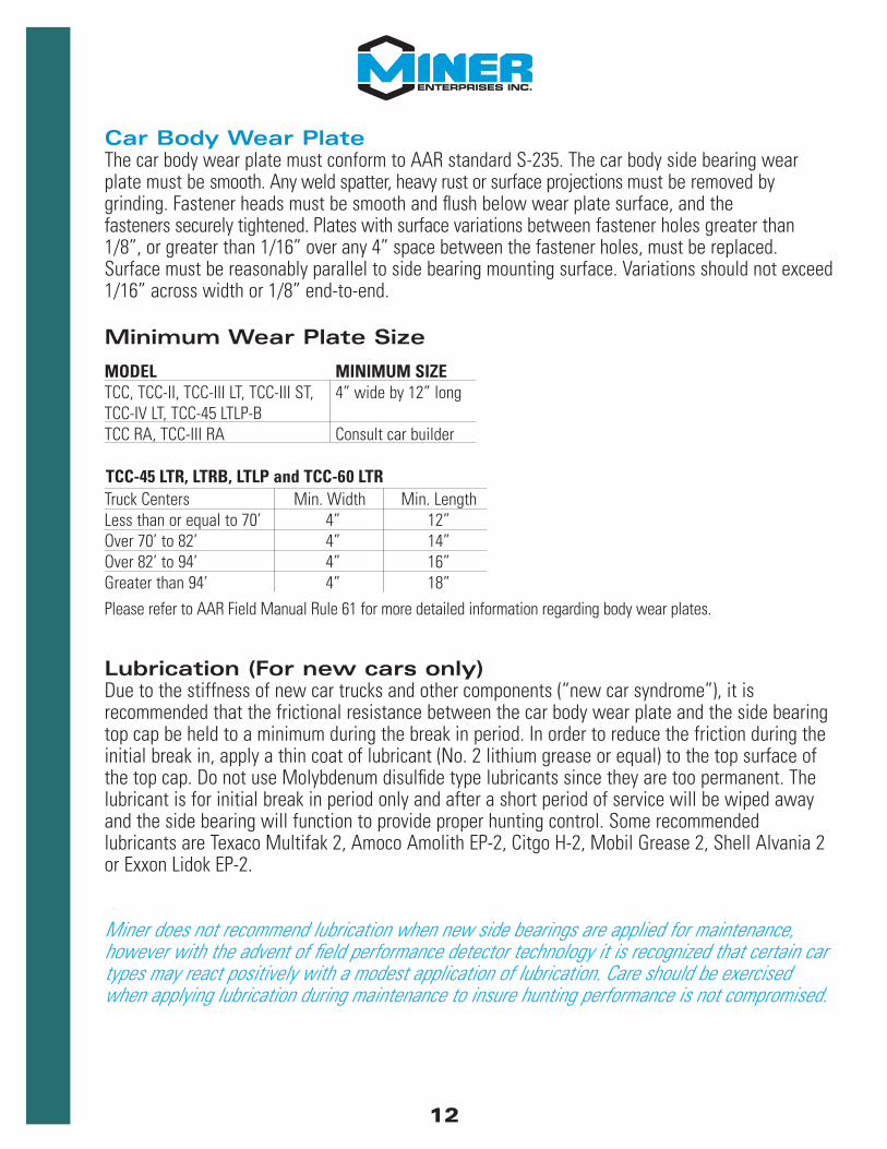
Truck Centers Min. Width Min. LengthLess than or equal to 70’ 4” 12”Over 70’ to 82’ 4” 14”Over 82’ to 94’ 4” 16”Greater than 94’ 4” 18”
Car Body Wear PlateThe car body wear plate must conform to AAR standard S-235. The car body side bearing wearplate must be smooth. Any weld spatter, heavy rust or surface projections must be removed bygrinding. Fastener heads must be smooth and flush below wear plate surface, and the fasteners securely tightened. Plates with surface variations between fastener holes greater than1/8”, or greater than 1/16” over any 4” space between the fastener holes, must be replaced.Surface must be reasonably parallel to side bearing mounting surface. Variations should not exceed1/16” across width or 1/8” end-to-end.
Minimum Wear Plate Size
TCC-45 LTR, LTRB, LTLP and TCC-60 LTR
Please refer to AAR Field Manual Rule 61 for more detailed information regarding body wear plates.
MODEL MINIMUM SIZETCC, TCC-II, TCC-III LT, TCC-III ST, 4” wide by 12” longTCC-IV LT, TCC-45 LTLP-BTCC RA, TCC-III RA Consult car builder
Lubrication (For new cars only)Due to the stiffness of new car trucks and other components (“new car syndrome”), it isrecommended that the frictional resistance between the car body wear plate and the side bearingtop cap be held to a minimum during the break in period. In order to reduce the friction during theinitial break in, apply a thin coat of lubricant (No. 2 lithium grease or equal) to the top surface ofthe top cap. Do not use Molybdenum disulfide type lubricants since they are too permanent. Thelubricant is for initial break in period only and after a short period of service will be wiped away and the side bearing will function to provide proper hunting control. Some recommendedlubricants are Texaco Multifak 2, Amoco Amolith EP-2, Citgo H-2, Mobil Grease 2, Shell Alvania 2or Exxon Lidok EP-2.
Miner does not recommend lubrication when new side bearings are applied for maintenance,however with the advent of field performance detector technology it is recognized that certain cartypes may react positively with a modest application of lubrication. Care should be exercisedwhen applying lubrication during maintenance to insure hunting performance is not compromised.
12

Side Bearing Installation – Bolt-on StyleThe housing should be mounted to the truck bolster pad utilizing one of the following fasteners:
Miner does not have a preference whether the bolt-head be on top of the housing or under the bolster.The orientation of the bolt-head is left up to the car owner.
Acceptable fasteners on all models EXCEPT the TCC-III RA:• Camcar standard dome head fastener (reference part #794-20100-130). • Huck fastener (reference part #C71LR-BR24-28/32 and #3LC-2R24GL). • 7/8”-9 Grade 5 or better HEX head bolt with self-locking nut.
Torque:– Dry: 375-425 ft.-lbs. (Produces a clamping force of 20,000-30,000 lbs. per bolt). – Waxed or well lubricated: 280-320 ft.-lbs. (Roughly 25% reduction from dry values).
Acceptable fasteners for the TCC-III RA ONLY:• Camcar flat head fastener (reference part #784-20156-140/160). • 7/8”-9 Grade 5 or better FLAT head bolt with self-locking nut.
Torque:– Dry: 375-425 ft.-lbs. (Produces a clamping force of 20,000-30,000 lbs. per bolt). – Waxed or well lubricated: 280-320 ft.-lbs. (Roughly 25% reduction from dry values).
Warning – Remove all C-Pep pads when installing constant contact side bearings.
TCCInstall top cap assembly into housing with the metal cap up. Ensure that top cap end slots matewith housing lugs. (Reference Fig.1 and 2, Page 5)
TCC-III LT/ST/RAThe TecsPak® pad inside diameter should easily slide onto the post inside the housing. There is a1/32” clearance between the post diameter at bottom and the inside diameter of the pad.Therefore, if the clearance is greater than 1/32”, the wrong pad has been applied. The top cappost should slide easily into the pad. With the TCC-III RA, install the base plate into therectangular section of the housing with the writing facing up, then place the roller on it. The carbody wear plate must cover the 3”-wide flat on the top cap. (Reference Figs. 4-6, Pages 5-6)
TCC-IV LTEach TCC-IV pad is supplied with a color-coded insulator attached to the top. Each pad assembly iscolor coded as follows: TCC-IV-30 (Green), TCC-IV-45 (Red), TCC-IV-60 (Blue) and TCC-IV-80 (Grey).The TecsPak® pad inside diameter should easily slide onto the post inside the housing with theinsulator facing up. There is a 1/32” clearance between the post diameter at bottom and theinside diameter of the pad. Therefore, if the clearance is greater than 1/32”, or it is difficult toassemble the pad over the housing post, the wrong pad has been applied. The top cap post shouldslide easily into the insulator/pad. The car body wear plate must cover the 3”-wide flat on the topcap. (Reference Fig. 7, Page 6)
13
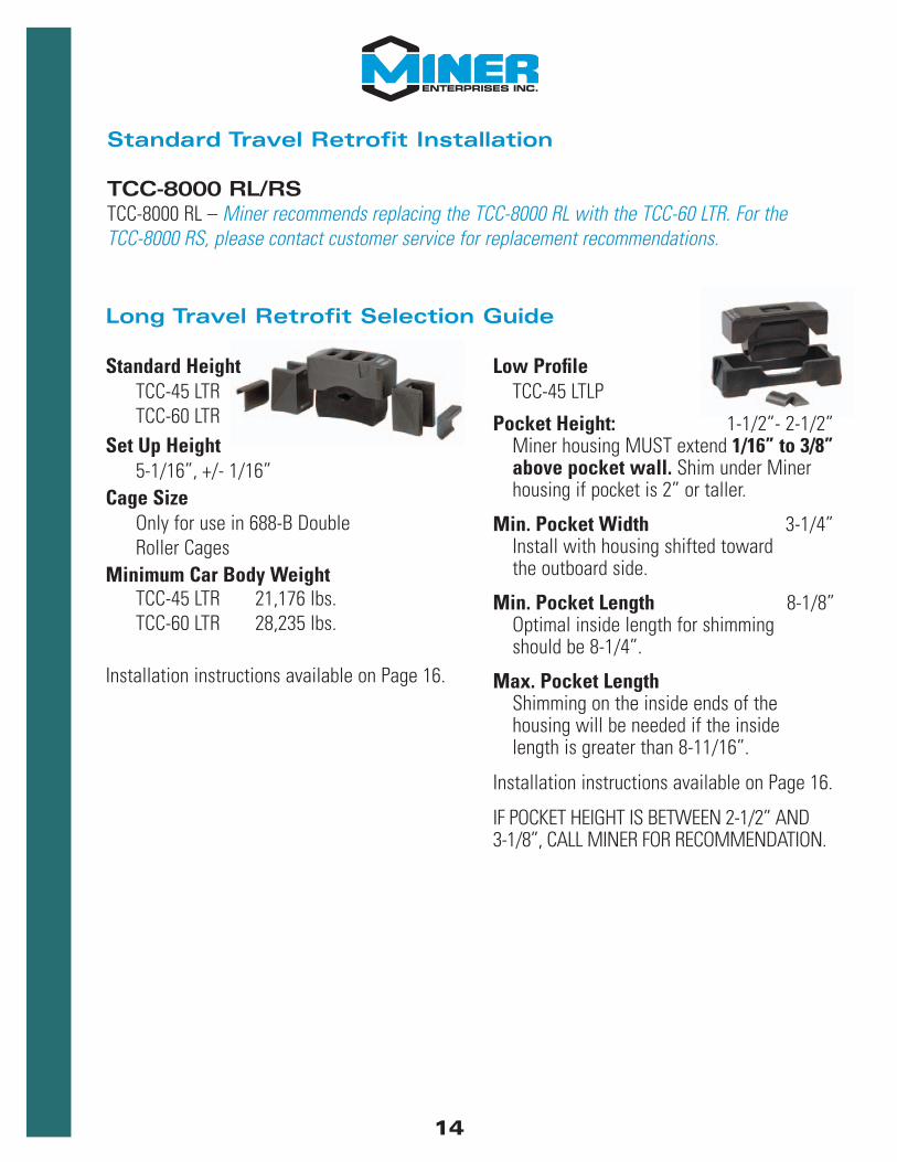
Standard Travel Retrofit Installation
TCC-8000 RL/RSTCC-8000 RL – Miner recommends replacing the TCC-8000 RL with the TCC-60 LTR. For the TCC-8000 RS, please contact customer service for replacement recommendations.
Low ProfileTCC-45 LTLP
Pocket Height: 1-1/2”- 2-1/2”Miner housing MUST extend 1/16” to 3/8”above pocket wall. Shim under Miner housing if pocket is 2” or taller.
Min. Pocket Width 3-1/4”Install with housing shifted toward the outboard side.
Min. Pocket Length 8-1/8”Optimal inside length for shimmingshould be 8-1/4”.
Max. Pocket LengthShimming on the inside ends of the housing will be needed if the inside length is greater than 8-11/16”.
Installation instructions available on Page 16.
IF POCKET HEIGHT IS BETWEEN 2-1/2” AND3-1/8”, CALL MINER FOR RECOMMENDATION.
Standard HeightTCC-45 LTRTCC-60 LTR
Set Up Height5-1/16”, +/- 1/16”
Cage SizeOnly for use in 688-B Double Roller Cages
Minimum Car Body WeightTCC-45 LTR 21,176 lbs.TCC-60 LTR 28,235 lbs.
Installation instructions available on Page 16.
14
Long Travel Retrofit Selection Guide

Low ProfileTCC-45 LTLP-B
Pocket Height 1-1/2”- 2-1/2”Miner housing MUST extend 1/16” to 3/8” above pocket wall. Shim under Miner housing if pocket is 2” or taller.
Min. Pocket Width 4-1/4”Install with housing shifted toward the outboard side.
Min. Pocket Length 9-1/4”Optimal inside length for shimmingshould be 9-3/8”.
Max. Pocket LengthShimming on the inside ends of the housing will be needed if the inside length is greater than 9-5/8”.
Installation instructions available on Page 17.
IF POCKET HEIGHT IS BETWEEN 2-1/2” AND3-1/8”, CALL MINER FOR RECOMMENDATION.
Standard HeightTCC-45 LTRB
Pocket Height 3-1/8”- 4-1/4”
Min. Pocket Width 4-1/8”Install with housing shifted toward the outboard side.
Min. Pocket Length 9”Optimal inside length for shimmingshould be 9-1/8”.
Max. Pocket LengthShimming on the inside ends of the housing will be needed if the inside length is greater than 9-1/4”.
Installation instructions available on Page 18.
IF POCKET HEIGHT IS BETWEEN 2-1/2” AND3-1/8”, CALL MINER FOR RECOMMENDATION.
15

TCC-45 LTLPPreparation - Remove the metal block and clean the pocket of any foreign material. Inspect thepocket for cracks or any other damage, and repair if necessary. Insure that the pocket bottom andend walls are relatively smooth and free of any weld spatter, bumps, etc. Remove all C-Pep padswhen installing constant contact side bearings.
Housing Placement - There are many different sizes of pockets that are currently in service.Smaller to medium sized pockets (see below dimensions) may only require two small wedges.
Miner recommends using the TCC-45 LTLP-B for pockets equal to or larger than9-1/4” x 4-1/4”.
The small wedges are designed to install the TCC-45 LTLP into the following smaller pocket dimensions:Minimum Inside Length: 8-1/8”Maximum Inside Length: 8-11/16” Minimum Inside Width: 3-1/4”
Long Travel Retrofit Installation
TCC-45/60 LTRPreparation – Remove the double rollers and clean the inside of the cage of any foreign material. Theexisting cage must be free of cracks, tears and deformation. The inside edges of the gibs at each endmust be free of upset metal that would prevent the over-solid stops or shims from fitting flush against theinside of the gibs. The heads of the cage fasteners must be flush or below the contour of the bottom ofthe cage. Cage fasteners must be tight.
Solid Stop Installation – The assembly requires that the two solid stops be placed on either end of thecage with the legs facing outward and orientated with the marked topside facing up.
Shim Adjustment – Install a 1/16” shim on both ends. After installing the top cap, push one solid stoptowards the opposite end of the housing. If the resulting gap between the shim and solid stop is greaterthat 1/16”, install thicker, 1/8” shim on one end and recheck. If the gap is too small and does not allowthe cap to move freely up and down, remove shims as necessary. (Reference Figs. 8 and 9, Page 7).
Fig. 18 TCC-45/60 LTR Solid Stop Installation
MAXIMUM 1/16” GAP
PUSH SOLID STOP TO OPPOSITE END
SOLID STOPVERTICAL DIRECTION
SOLID STOP LEGSFACE TOWARD
CAGE GIBS
16

TCC-45 LTLP-BPreparation - Remove the metal block and clean the pocket of any foreign material. Inspect thepocket for cracks or any other damage, and repair if necessary. Insure that the pocket bottom andend walls are relatively smooth and free of any weld spatter, bumps, etc. Remove all C-Pep padswhen installing constant contact side bearings.
Housing Placement - The long wedges are designed to install the TCC-45 LTLP-B into the followingpocket dimensions:
Minimum Inside Length: 9-1/4” Maximum Inside Length: 9-5/8” Optimal Inside Length when Shimming: 9-3/8” Minimum Inside Width: 4-1/4”
(For oversized pockets, see Pocket Adjustment instructions on Page 19.)
TCC-45 LTLP Installation1. Shift the housing in the pocket to the outboard side of the bolster.2. Center housing along its length in the pocket and insert small wedges in both ends.3. Insure that the flat side of the wedge is against the Miner housing and the rounded side is
against the pocket wall.4. Insure that the wedges on the ends are approximately at the same height and that all wedges do
not extend beyond the housing top surface. 5. Securing the housing to the pocket requires welding.
See welding requirements on Page 19.
Fig. 19 Pocket Installation POCKET
OUTBOARD SIDE OF BOLSTER
Fig. 20 TCC-45 LTLP-B
17

FILL GROOVE WITH 70KSI MINIMUM TENSILE STRENGTH WELD MATERIAL
Fig. 21 TCC-45 LTRBHousing Securement
TCC-45 LTRBPreparation - Remove the metal block and clean the pocket of any foreign material. Inspect the pocketfor cracks or any other damage, and repair if necessary. Insure that the pocket bottom and end wallsare relatively smooth and free of any weld spatter, bumps, etc. Remove all C-Pep pads when installingconstant contact side bearings.
Housing Placement – The assembly only requires one set of wedges. Center housing in pocket andinsert proper wedges in both ends.
1. Make sure that the flat side of the wedge is against the Miner housing and the rounded side is against the pocket.
2. Insure that both wedges are approximately at the same height and that they do not extend beyond the housing top surface.
3. Securing the housing to the pocket requires welding.See welding requirements on Page 19.
Warning – Do not weld directly on Miner housing.
Install top cap assembly into housing with the metal cap up. (Reference Fig.14, Page 8)
TCC-45 LTLP-B Installation1.Shift the housing in the pocket to the outboard side of the bolster. 2.Center housing along its length in the pocket and insert wedges in both ends. 3.Insure that the flat side of the wedge is against the Miner housing and rounded side is against
the pocket wall. 4.Insure that the wedges do not extend beyond the housing top surface. 5.Securing the housing to the pocket requires welding.
See welding requirements on Page 19.
18

Pocket Size AdjustmentSome pockets may be slightly larger than the TCC-45 LTLP or LTLP-B are designed to fit into. Forthese applications, follow the procedures below.
TCC-45 LTLPInside Length - If the wedges hit the pocket floor before contacting the end wall (inside lengthgreater than 8-11/16”), shim application is required. Optimal inside length after shimming shouldbe 8-1/4”. Fabricate the shim so that it is 1/4” shorter than the pocket wall and no wider than theflat portion of the end wall. Leave enough room on the shim width for welding. Fillet weld theshim to one end of the pocket using 70-ksi minimum tensile strength weld material.
Inside Width - If the addition of wedges to the inboard side of the pocket still leaves a gap ofgreater than 1/8” (inside width greater than 4-5/16”), please use the TCC-45 LTLP-B. Estimate theshim thickness needed to reduce the gap between wedge and the pocket wall to 1/8” or less.Fabricate the shim so that it is approximately 1/4” shorter than the pocket wall and no longer thanthe flat portion of the pocket side wall. Leave enough room on the shim length for welding. Filletweld the shim to the outboard side of the pocket using 70-ksi minimum tensile strength weldmaterial.
Housing Securement Welding Procedure(TCC-45 LTLP, LTLP-B AND LTRB)
Remove the top cap assembly from housing prior to welding.
Warning – Do not weld near the top cap assembly.
Warning – Do not weld directly to either Miner housing ortop cap.
Flare bevel groove weld wedge to pocket wall (1-1/2” minimum length) with 70-ksi minimum tensilestrength weld material. If the wedge is below the pocket wall, add reinforcement fillet weld on top.Insure that weld and pocket wall are at least 1/16” below housing wall. All surface preparation andwelding must comply with ANSI/AWS D15.1 Railroad Welding Specification – Cars and Locomotives,latest edition, including preheat when required.
POCKET WALL
WEDGE
Fig. 22 Welding Procedure– Cross Section
19
1/4”
OUTBOARD SIDEOF BOLSTER
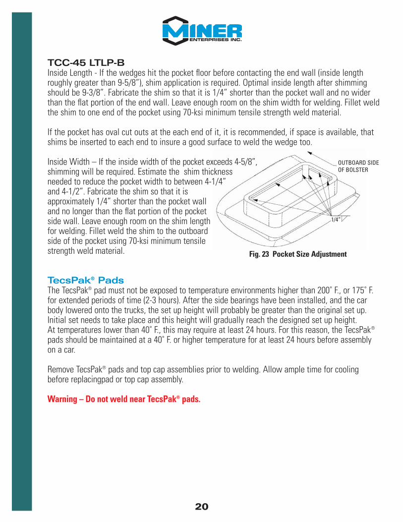
TCC-45 LTLP-BInside Length - If the wedges hit the pocket floor before contacting the end wall (inside lengthroughly greater than 9-5/8”), shim application is required. Optimal inside length after shimmingshould be 9-3/8”. Fabricate the shim so that it is 1/4” shorter than the pocket wall and no widerthan the flat portion of the end wall. Leave enough room on the shim width for welding. Fillet weldthe shim to one end of the pocket using 70-ksi minimum tensile strength weld material.
If the pocket has oval cut outs at the each end of it, it is recommended, if space is available, thatshims be inserted to each end to insure a good surface to weld the wedge too.
Inside Width – If the inside width of the pocket exceeds 4-5/8”,shimming will be required. Estimate the shim thicknessneeded to reduce the pocket width to between 4-1/4”and 4-1/2”. Fabricate the shim so that it isapproximately 1/4” shorter than the pocket walland no longer than the flat portion of the pocketside wall. Leave enough room on the shim lengthfor welding. Fillet weld the shim to the outboardside of the pocket using 70-ksi minimum tensilestrength weld material.
TecsPak® PadsThe TecsPak® pad must not be exposed to temperature environments higher than 200˚ F., or 175˚ F.for extended periods of time (2-3 hours). After the side bearings have been installed, and the carbody lowered onto the trucks, the set up height will probably be greater than the original set up.Initial set needs to take place and this height will gradually reach the designed set up height. At temperatures lower than 40˚ F., this may require at least 24 hours. For this reason, the TecsPak®
pads should be maintained at a 40˚ F. or higher temperature for at least 24 hours before assemblyon a car.
Remove TecsPak® pads and top cap assemblies prior to welding. Allow ample time for coolingbefore replacingpad or top cap assembly.
Warning – Do not weld near TecsPak® pads.
Fig. 23 Pocket Size Adjustment
20

INSPECTION
For side bearing wear limits and cause for renewal, please refer to Rule 62 of the Field Manualof the AAR Interchange Rules.
Rule 62 has a couple of notes that dictate which location should be summed.1. For articulated cars, "sum of the pairs" refers to the side bearings laterally across from each other. 2. For stand alone cars, the following locations must be summed:
• AL+AR • BL+BR • AL+BR • AR+BL
Set Up HeightThe set up height is the vertical distance between the car body side bearing wear plate and thehousing mounting surface.
Field or Yard InspectionConstant contact side bearing heights:
- For cars with 5-1/16 inch setup height and 8-1/2 inch mounting holes. Typically on 4-axle cars and end trucks of articulated cars.
Height adjustment is required at any time, empty loaded, when height measured is:
Sum-of-the-Pairs Measurement(Condemning Limit)
Less than 9-3/4 inchor
Greater than 10-1/2 inch
- For articulated cars at the articulated truck locations.
21

Height adjustment is required at any time, empty or loaded, when height measurement is:
Articulated Nominal Setup Sum-of-the-PairsConnector Height (or as Measurement
Portion stenciled on car) (Condemning Limit)
Female 5-1/16 inch Less than 9-3/4 inchor
Greater than 10-3/8 inch
Male 5-3/16 inch Less than 9-3/4 inchor
Greater than 10-5/8 inch
Either Any Other Less than 9-3/4 inch(Female oror Male) Greater than 1/4 inch above
two times the stenciledset-up height
- For cars with low profile or standard height solid block style side bearing pockets (integral cast or welded on ring).
Height adjustment is required at any time, empty or loaded, when height measurement is:
- For articulated cars at the articulated truck locations.
Sum-of-the-Pairs Measurement(Condemning Limit)
Less than 7/8 inchor
Greater than 1-5/8 inch
22

Articulated Nominal Setup Single Side BearingConnector Height (or as Measurement
Portion stenciled on car) (Condemning Limit)
Female 5-1/16 inch Less than 4-15/16 inchor
Greater than 5-1/8 inch
Male 5-3/16 inch Less than 4-15/16 inchor
Greater than 5-1/4 inch
Either Any Other Less than 4-15/16 inch(Female oror Male) Greater than 1/16 inch
the nominal set-up height
Single Side Bearing Measurement(Condemning Limit)
Less than 4-15/16 inchor
Greater than 5-3/16 inch
Shop or Repair Track InspectionConstant contact side bearing heights:
- For cars with 5-1/16 inch setup height and 8-1/2 inch mounting holes. Typically on 4-axle cars and end trucks of articulated cars.
Height adjustment is required at any time, empty or loaded, when on a Repair Shop (Facility)/RepairTrack as defined in Appendix A and height measurement is:
- For articulated cars at the articulated truck locations.
Height adjustment is required at any time, empty or loaded, when on a Repair Shop (Facility)/Repair Track as defined in Appendix A and height measurement is:
23

- For cars with low profile or standard height solid block style side bearing pockets (integral cast orwelded on ring).
Height adjustment is required at any time, empty or loaded, when on a Repair Shop(Facility)/Repair Track as defined in Appendix A and height measurement is:
2-7/16”
TCC-45 LTRBHOUSING
2-11/16”
LTLP TOP CAPTCC-45 LTR TOP CAP(PARTING LINE)
LTLP HOUSING
Fig. 25 Block Style Retrofit Set Up Height Indicators
5-1/8”4-7/8”
BOTTOM EDGE OFTCC-III OR TCC-IV TOP CAP
NEWER STYLE LONGTRAVEL HOUSING TCC-III TOP CAP
TCC LTR TOP CAP
DOUBLE ROLLER CAGE
OLD STYLE TCC-III HOUSING
Single Side Bearing Measurement(Condemning Limit)
Less than 1/2 inchor
Greater than 3/4 inch
Some models include cast-in markings to assist in a rough estimate of the set up height.
Fig. 24 Standard Set Up Height Indicators
5”
5-1/8”
Some models include cast-in markings to assist in a rough estimate of the set up height.
4-7/8”
5-1/8”
4-7/8”5-1/8”
24

Fig. 26 TCC-IV Wear Indicator
Fig. 27 TCC-45/60 LTR & LTRB Wear Indicator
Fig. 28 TCC-45 LTLP-B Wear Indicator
Fig. 29 TCC-45 LTLP Wear Indicator
TCC-IV WEAR INDICATOR
TCC-45 LTLP-B WEAR INDICATOR
TCC-45/60 LTR & LTRB WEAR INDICATOR TCC-45 LTLP WEAR INDICATOR
GeneralYard or Field – The housing and top cap castings must be free of cracks and be securely fastened tothe truck bolster. Do not shop a car because of TCC-II bolt wear. The bolt wear does not affect thesafe operation of the car.
Shop or Repair Track – Inspect metal parts for cracks and the TecsPak® pads for melting; replace inkind. For optimal performance, it is recommended if the clearance between the top cap OD and thehousing ID is greater than 1/8”, install new top cap and re-measure. If the clearance is stillgreater than 1/8”, replace both top cap and housing.
Top Cap Wear IndicatorsSome of Miner’s top caps have built-in wear indicators that will allow the inspector to determineif the top cap has been worn down due to contact with the car body wear plate. If the indicatorhas been worn down flush to the bottom surface the top cap will need to be replaced.
The models that have this feature are the TCC-IV, TCC-45 LTR, LTRB, LTLP, LTLP-B, and the TCC-60 LTR.
25

TecsPak® Pad Free Height MeasurementShop or Repair Track – The spring used in Miner constant contact side bearings is called aTecsPak® pad. With use, the pads can lose some of their preload. For optimal performance, thefree height of the pad should be measured to determine suitability for continued service.
TCCTo determine if the TecsPak® elastomer pad has sufficient preload, measure the free height ofthe top cap assembly. To do this, remove the top cap assembly from the housing, then allow twohours for the pad to stabilize. For optimal performance, it is recommended the top cap assemblybe greater than the following heights:
TCC-2600 4-5/8” TCC-4500 4-3/4” TCC-8000 4-1/2”
Fig. 30 TecsPak® Pad Free Height Measurement
TCC-IIThe TCC-II side bearings are pre-assembled at the factory and normally should not need to bedisassembled. The TecsPak® pads are contained within the housing and top cap. The top cap is heldin position by two retaining bolts, thus maintaining approximately 2,000 lbs. on the pads when theside bearing is at free height (5-7/8”).
Warning - Under no circumstances should the retaining bolts be removed unless the sidebearing has been compressed to relieve the load on the bolts.
Both sides of the bolts will develop a flat spot after a certain amount of service. If the bolts arebroken, missing, or worn to less than 1⁄4” in thickness, the entire assembly will need to bereplaced. Both sides of the truck will need to be replaced at the same time. Contact Miner for replacement recommendation for the side bearing assembly.
Warning - Do not use standard bolts. Contact Miner for replacement recommendationfor the side bearing assembly.
When the car body is raised off the side bearing, the top cap should extend to free height. If thebottom of the top cap slot does not maintain contact with the bottom of the retaining bolts,replace side bearing per owners’ instructions.
26

TCC III AND IV FREE HEIGHT INSPECTIONTo determine if the TecsPak elastomer pad has sufficient preload, measure the free height of thepad. To do this, remove the pad from the assembly, allow 1 minute for pad to stabilize. For optimalperformance, it is recommended the pad be greater than:
All Models: 3-15/16”
TCC LTR, LTLP, LTLP-B and LTRBTo determine if the TecsPak® elastomer pad has sufficient preload, measure the free height of the top cap assembly. To do this, remove the top cap assembly from the housing, then allow two hours for the pad to stabilize. For optimal performance, it is recommended the top cap assembly begreater than the following heights:
TCC-45 LTR 4-13/16”TCC-60 LTR 4-7/8”TCC-45 LTLP 2-15/16”TCC-45 LTLP-B 2-15/16”TCC-45 LTRB 4-13/1
27

Brake Beams
Side Bearings
Draft Gears
INSTALLATION AND INSPECTION GUIDEINSTALLATION AND INSPECTION GUIDE
1-630-232-3000 VERSION 6
Perfecting Railcar Performance

DRAFT GEARS
GENERAL DESCRIPTION
Miner offers a variety of draft gears to satisfy your car protection requirements.
Crown SG™ is Miner’s all-steel draft gear that meets AAR Specification M-901G. Itsrobust spring package provides maximum protection for the industry’s heaviest cars.The Crown SG can be used in any freight car including intermodal and stand-alone125-ton cars.
Crown SE™ is a high capacity all-steel draft gear certified under AAR specification M-901E. The Crown SE is engineered to provide long service life in freight cars with minimum wear of draft gear pocket and attachments.
TF-880™ is the lightest weight high performance draft gear meeting AAR specification M-901E. The TF-880 incorporates Miner’s proven friction clutch design in combinationwith the patented TecsPak® elastomer compression spring package to provideexceptional car protection. It is an ideal all-purpose gear, suitable for all freight cars upto and including 110-ton capacity.
SL-76™ is specifically designed to meet the most severe requirements of today’s railcars.Miner’s service proven friction clutch mechanism and natural rubber spring packageprovide extra heavy-duty car protection and less operating slack.
28

PROCEDURE FOR DETERMINING SERVICEABILITY OF MINER DRAFT GEARS
Crown SE™ and Crown SG™ (In-car Inspection)Inspect for excessive draft slack, coupler horn/striker contact, and excessive wear on carrier plateand sill walls, indicating possible unsatisfactory draft gear performance. To remain in service, draftgear should be tight in pocket and free of loose or broken parts. Change out draft gear ifprotrusion of both shoes out of the housing averages 11/16” or more.
Crown SE™ and Crown SG™ (Out-of-car Inspection)1. Tap friction plate in with hammer.2. Bridge wedges and measure gap between wedges and friction plate.3. If less than 1/8” gap, gear should be reconditioned (do not reapply).
Fig. 31 Crown SE/SG In-Car Inspection
MEASURE PROTRUSION
OF EACH SHOE
Fig. 32 Crown SE/SG Out-of-Car Inspection
BRIDGEGAP1/8”
MINIMUM
1 - FRICTION PLATE
2 - WEDGES
2 - SHOES
Before applying any draft gear, inspect for conformance to AAR Rule 21, Sections A & B.
29

TF-880™ (In-car Inspection)Inspect for excessive draft slack, coupler horn/striker contact, and excessive wear on carrier plateand sill walls, indicating possible unsatisfactory draft gear performance. To remain in service, draftgear should be tight in pocket and free of loose or broken parts. Change out draft gear ifprotrusion of the three shoes out of the housing averages 1-1/8” or more.
TF-880™ (Out-of-car Inspection)1. Wedge protrusion should measure approx. 3-5/16” (draft gear not preshortened).2. If shoe protrusion averages 1-5/16” or more, gear should be reconditioned (Do not reapply).
Before applying any draft gear, inspect for conformance to AAR Rule 21, Sections A & B.
Fig. 33 TF-880 In-Car Inspection
MEASURE PROTRUSION
OF EACH SHOE
Fig. 34 TF-880 Out-of-Car Inspection
MEASURE THE HEIGHT
OF EACH SHOEAND AVERAGE
WEDGE
HOUSINGSHOES
WEDGEPROTRUSION
30

SL-76™ (In-car Inspection)Inspect for excessive draft slack, coupler horn/striker contact, and excessive wear on carrier plateand sill walls, indicating possible unsatisfactory draft gear performance. To remain in service, draftgear should be tight in pocket and free of loose or broken parts. Change out draft gear ifprotrusion of the three shoes out of the housing averages 1-1/8” or more.
SL-76™ (Out-of-car Inspection)1. Wedge protrusion should measure approx. 3-5/16” (draft gear not preshortened).2. If shoe protrusion averages 1-5/16” or more, gear should be reconditioned (Do not reapply).
Before applying any draft gear, inspect for conformance to AAR Rule 21, Sections A & B.
Fig. 35 SL-76 In-Car Inspection
MEASURE PROTRUSION
OF EACH SHOE
Fig. 36 SL-76 Out-of-Car Inspection
MEASURE THE HEIGHT
OF EACH SHOEAND AVERAGEWEDGE
HOUSING
SHOES
WEDGEPROTRUSION
31

Brake Beams
Side Bearings
Draft Gears
INSTALLATION AND INSPECTION GUIDEINSTALLATION AND INSPECTION GUIDE
1-630-232-3000 VERSION 6
Perfecting Railcar Performance
BRAKE BEAMS
GENERAL DESCRIPTION
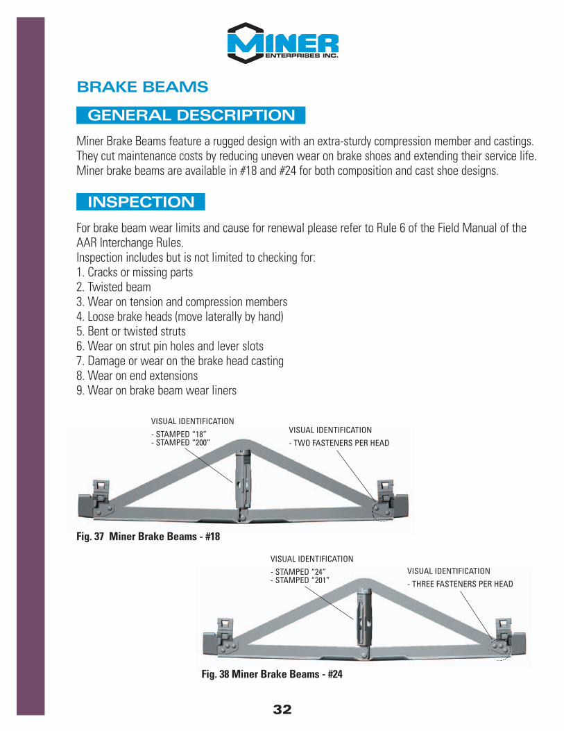
Miner Brake Beams feature a rugged design with an extra-sturdy compression member and castings.They cut maintenance costs by reducing uneven wear on brake shoes and extending their service life.Miner brake beams are available in #18 and #24 for both composition and cast shoe designs.
INSPECTION
For brake beam wear limits and cause for renewal please refer to Rule 6 of the Field Manual of theAAR Interchange Rules.Inspection includes but is not limited to checking for:1. Cracks or missing parts2. Twisted beam3. Wear on tension and compression members4. Loose brake heads (move laterally by hand)5. Bent or twisted struts6. Wear on strut pin holes and lever slots7. Damage or wear on the brake head casting8. Wear on end extensions9. Wear on brake beam wear liners
Fig. 37 Miner Brake Beams - #18
Fig. 38 Miner Brake Beams - #24
VISUAL IDENTIFICATION
- STAMPED “18”- STAMPED “200”
VISUAL IDENTIFICATION
- TWO FASTENERS PER HEAD
VISUAL IDENTIFICATION
- STAMPED “24”- STAMPED “201”
VISUAL IDENTIFICATION
- THREE FASTENERS PER HEAD
32
STRUT HAND CHANGE PROCEDURE
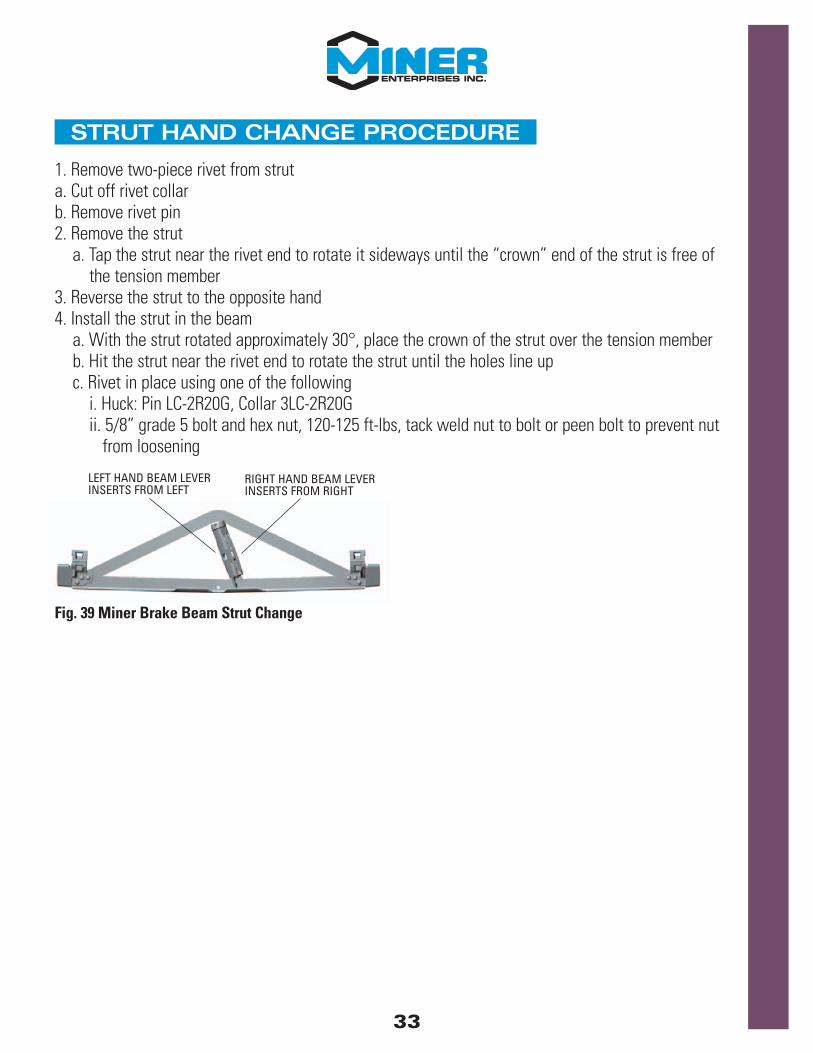
1. Remove two-piece rivet from struta. Cut off rivet collarb. Remove rivet pin2. Remove the strut
a. Tap the strut near the rivet end to rotate it sideways until the “crown” end of the strut is free of the tension member
3. Reverse the strut to the opposite hand4. Install the strut in the beam
a. With the strut rotated approximately 30°, place the crown of the strut over the tension memberb. Hit the strut near the rivet end to rotate the strut until the holes line upc. Rivet in place using one of the following
i. Huck: Pin LC-2R20G, Collar 3LC-2R20Gii. 5/8” grade 5 bolt and hex nut, 120-125 ft-lbs, tack weld nut to bolt or peen bolt to prevent nut
from loosening
Fig. 39 Miner Brake Beam Strut Change
LEFT HAND BEAM LEVERINSERTS FROM LEFT
RIGHT HAND BEAM LEVERINSERTS FROM RIGHT
33