69-2065efs 07 - thp9045 wiring module - honeywell · thp9045 wiring module 69-2065efs—07 2 fig....
TRANSCRIPT

INSTALLATION INSTRUCTIONS
Place Bar Code Here
69-2065EFS-07
THP9045 Wiring Module
APPLICATIONThe THP9045 Wiring Module is designed to be used with applicable thermostats in which a 24V common is required and there are not enough wires. The K terminal on the thermostat can be used to operate both the fan and compressor on a single wire, and the module is designed to receive the signal from the K terminal, split that signal and re-route it to operate the compressor, and/or fan for normal operation.
Use with the following thermostats:— THX9321R— THX9321R5000— THX9321R1008— TH8320UP1003— T5060F7088
FEATURES• Can be used when a common wire is required.• Mounts easily on or near HVAC equipment.
INSTALLATION1. The THP9045 Wiring Module can be equipment- or
wall-mounted in any orientation or as dictated by the surroundings.
2. Precise leveling of the THP9045 module is not required.
3. Identify the four wires in the wall and connect to the R, C, W, and K terminals on the thermostat.
4. Wire the K terminal on the thermostat to the K ter-minal on the THP9045 module.
5. Wire the R and C terminals on the thermostat to the R (power) and C (common) terminals on the THP9045 module and equipment.
6. Wire the W terminal from the thermostat to the W (heat relay) terminal on the HVAC equipment.
7. Wire the Y and G terminals on the Module to the Y (Compressor Relay) and G (Fan Relay) terminals on the HVAC equipment.
TERMINALSR 24VC 24V CommonY Cooling relayG Fan relayK Communication
WIRESAVER
W-O/BRc K C
W-O/BRc Y G C
Honeywell THP9045A
EQUIPMENT
THERMOSTAT
M31301A

THP9045 WIRING MODULE
69-2065EFS—07 2
Fig. 1. Example wiring diagram for 1H/1C conventional application.
Fig. 2. Example wiring diagram for a 2H/1C conventional application.
THX9321R SUBBASE
G CR YFURNACE
W
W-O/BRc Y G C
Honeywell THP9045A
WIRESAVER
M31302A
O/B W
AUX/E W2
Y Y
Y2 Y2
G G
LNOTUSED
NOTUSED
NOTUSED
K
C
Rc
R
U2 U2
U2 U2
U1 U1
U1 U1
K
C
Rc
R
NOTUSED
NOTUSED
HEAT PUMP
CONVENTIONAL
W-O/BRc K C
THX9321R SUBBASE
G C WR YW2M31305AFURNACE
W-O/BRc Y G C
WIRESAVER
O/B W
AUX/E W2
Y Y
Y2 Y2
G G
LNOTUSED
NOTUSED
NOTUSED
K
C
Rc
R
U2 U2
U2 U2
U1 U1
U1 U1
K
C
Rc
R
NOTUSED
NOTUSED
HEAT PUMP
CONVENTIONAL
Honeywell THP9045A
W-O/BRc K C

THP9045 WIRING MODULE
3 69-2065EFS—07
Fig. 3. Example wiring diagram for a 2H/2C conventional application.
Fig. 4. Example wiring diagram for a 1H/1C system with 2 transformers.
THX9321R SUBBASE
G C OR YAIR HANDLER
Y2 W2
W-O/BRc Y G C
WIRESAVER
M31306A
O/B W
AUX/E W2
Y Y
Y2 Y2
G G
LNOTUSED
NOTUSED
NOTUSED
K
C
Rc
R
U2 U2
U2 U2
U1 U1
U1 U1
K
C
Rc
R
NOTUSED
NOTUSED
HEAT PUMP
CONVENTIONAL
Honeywell THP9045A
W-O/BRc K C
G CR Y
HEATERRW
AIR HANDLER
WIRESAVERTHX9321R SUBBASE
W-O/BRc Y G C
M31300A
Honeywell THP9045A
O/B W
AUX/E W2
Y Y
Y2 Y2
G G
LNOTUSED
NOTUSED
NOTUSED
K
C
Rc
R
U2 U2
U2 U2
U1 U1
U1 U1
K
C
Rc
R
NOTUSED
NOTUSED
HEAT PUMP
CONVENTIONAL
W-O/BRc K C
REMOVE R/Rc JUMPER1
1

THP9045 WIRING MODULE
Automation and Control SolutionsHoneywell International Inc.1985 Douglas Drive NorthGolden Valley, MN 55422
Honeywell Limited-Honeywell Limitée35 Dynamic DriveToronto, Ontario M1V 4Z9http://customer.honeywell.com
® U.S. Registered Trademark© 2010 Honeywell International Inc.69-2065EFS—07 M.S. Rev. 12-10 Printed in U.S.A.
Fig. 5. Example wiring diagram for a 2H/1C heat pump application.
Fig. 6. Example wiring diagram for a 3H/2C heat pump application.
THX9321R SUBBASE
G C OR YEMATCH THE WIRES FROM THE HEAT PUMP TO THE AIR HANDLER AS NORMAL.1
1
AIR HANDLER
W-O/BRc Y G C
WIRESAVER
M31303A
O/B W
AUX/E W2
Y Y
Y2 Y2
G G
LNOTUSED
NOTUSED
NOTUSED
K
C
Rc
R
U2 U2
U2 U2
U1 U1
U1 U1
K
C
Rc
R
NOTUSED
NOTUSED
HEAT PUMP
CONVENTIONAL
Honeywell THP9045A
1W-O/BRc K C
THX9321R SUBBASE
G C OR YAIR HANDLER
1
1
Y2 E
MATCH THE WIRES FROM THE HEAT PUMP TO THE AIR HANDLER AS NORMAL.
W-O/BRc Y G C
WIRESAVER
M31304A
O/B W
AUX/E W2
Y Y
Y2 Y2
G G
LNOTUSED
NOTUSED
NOTUSED
K
C
Rc
R
U2 U2
U2 U2
U1 U1
U1 U1
K
C
Rc
R
NOTUSED
NOTUSED
HEAT PUMP
CONVENTIONAL
Honeywell THP9045A1
W-O/BRc K C

NOTICE D'INSTALLATION
Module de câblage THP9045
APPLICATIONLe module de câblage THP9045 est conçu pour être utilisé avec les thermostats compatibles dans lesquels un fil commun de 24 V est requis et lorsqu'il n'y a pas assez de fils. La borne K du thermostat peut servir à faire fonctionner le ventilateur et le compresseur au moyen d'un seul fil. Le module, qui reçoit le signal de la borne K, sépare ce signal et le dirige pour faire fonctionner de façon normale le compresseur et le ventilateur.
Ce module peut être utilisé avec les thermostats suivants :
— THX9321R— THX9321R5000— THX9321R1008— TH8320UP1003— T5060F7088
CARACTÉRISTIQUES :• Peut être utilisé lorsqu'un fil commun est requis.• S'installe facilement sur le système de CVCA ou à
proximité.
INSTALLATION1. Le module THP9045 peut être installé sur le
système de CVCA ou sur un mur. Le sens de montage n'a pas d'importance et dépend l'emplacement.
2. Il n'est pas nécessaire d'installer le module THP9045 de niveau.
3. Identifier les quatre fils qui passent dans le muret les raccorder aux bornes R, C, W et K du thermostat.
4. Raccorder la borne K du thermostat à la borne K du module THP9045.
5. Raccorder les bornes R et C du thermostat aux bornes R (alimentation) et C (neutre) du module THP9045 et du système.
6. Raccorder la borne W du thermostat à la borne W (relais de chauffage) sur le système de CVCA.
7. Raccorder les bornes Y et G du module aux bornes Y (relais du compresseur) et G (relais du ventilateur) sur le système de CVCA.
BORNESR 24VC 24V CommunY Relais de refroidissementG Relais de ventilateurK Communication
PROTECTEUR DE FIL
W-O/BRc Y G C
Honeywell THP9045A
ÉQUIPEMENT
THERMOSTAT
MF31301A
W-O/BRc K C

MODULE DE CÂBLAGE THP9045
69-2065EFS—07 6
Fig. 1. Exemple de schéma de câblage pour une application conventionnelle à 1 étage de chauffage/1 étage de refroidissement (1H/1C).
Fig. 2. Exemple de schéma de câblage pour une application conventionnelle à 2 étages de chauffage/1 étage de refroidissement (2H/1C).
PLAQUE DE RACCORDEMENT THX9321R
G CR Y
APPAREIL DE CHAUFFAGEW
W-O/BRc Y G C
Honeywell THP9045A
PROTECTEURDE FIL
MF31302A
O/B W
AUX/E W2
Y Y
Y2 Y2
G G
L
K
C
Rc
R
U2 U2
U2 U2
U1 U1
U1 U1
K
C
Rc
R
HEAT PUMP
CONVENTIONAL
NOTUSED
W-O/BRc K C
NOTUSED
NOTUSED
NOTUSED
NOTUSED
PLAQUE DE RACCORDEMENT THX9321R
G C WR YW2
MF31305A
APPAREIL DE CHAUFFAGE
W-O/BRc Y G C
PROTECTEURDE FIL
O/B
AUX/E
Y
Y2
G
L
K
U2
U2
U1
U1
C
Rc
R Honeywell THP9045A
W-O/BRc K C
NOTUSED
NOTUSED
W
W2
Y
Y2
G
C
Rc
R
U2
U2
U1
U1
K
HEAT PUMP
CONVENTIONAL
NOTUSED
NOTUSED
NOTUSED
MODULE DE CÂBLAGE THP9045
7 69-2065EFS—07
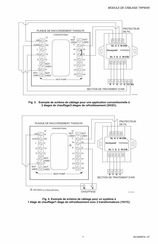
Fig. 3. Exemple de schéma de câblage pour une application conventionnelle à 2 étages de chauffage/2 étages de refroidissement (2H/2C).
Fig. 4. Exemple de schéma de câblage pour un système à 1 étage de chauffage/1 étage de refroidissement avec 2 transformateurs (1H/1C).
PLAQUE DE RACCORDEMENT THX9321R
G C OR Y
SECTION DE TRAITEMENT D’AIR
Y2 W2
W-O/BRc Y G C
PROTECTEURDE FIL
MF31306A
O/B W
AUX/E W2
Y Y
Y2 Y2
G G
L
K
C
Rc
R
U2 U2
U2 U2
U1 U1
U1 U1
K
C
Rc
R
HEAT PUMP
CONVENTIONAL
Honeywell THP9045A
W-O/BRc K C
NOTUSED
NOTUSED
NOTUSED
NOTUSED
NOTUSED
G CR Y
CHAUFFAGERW
SECTION DE TRAITEMENT D’AIR
PROTECTEURDE FILPLAQUE DE RACCORDEMENT THX9321R
W-O/BRc Y G C
MF31300A
Honeywell THP9045A
O/B W
AUX/E W2
Y Y
Y2 Y2
G G
L
K
C
Rc
R
U2 U2
U2 U2
U1 U1
U1 U1
K
C
Rc
R
CONVENTIONAL
W-O/BRc K C
RETIRER LE CAVALIER R/Rc1
1
NOTUSED
NOTUSED
NOTUSED
NOTUSED
NOTUSED
HEAT PUMP

MODULE DE CÂBLAGE THP9045
Solutions de régulation et d’automatisationHoneywell International Inc.1985 Douglas Drive NorthGolden Valley, MN 55422
Honeywell Limited-Honeywell Limitée35, Dynamic DriveToronto (Ontario) M1V 4Z9http://customer.honeywell.com
® Marque de commerce déposée aux É.-U.© 2010 Honeywell International Inc. Tous droits réservés69-2065EFS—07 M.S. Rev. 12-10Imprimé aux États-Unis
Fig. 5. Exemple de schéma de câblage pour une application à thermopompe à 2 étages de chauffage/1 étage de refroidissement (2H/1C).
Fig. 6. Exemple de schéma de câblage pour une application à thermopompe à 3 étages de chauffage/2 étages de refroidissement (3H/1C).
PLAQUE DE RACCORDEMENT THX9321R
G C OR YEFAIRE CORRESPONDRE NORMALEMENT LES FILS DE LATHERMOPOMPE À LA SECTION DE TRAITEMENT DE L’AIR.
1
1
SECTION DE TRAITEMENT D’AIR
W-O/BRc Y G C
PROTECTEURDE FIL
MF31303A
O/B W
AUX/E W2
Y Y
Y2 Y2
G G
L
K
C
Rc
R
U2 U2
U2 U2
U1 U1
U1 U1
K
C
Rc
R
HEAT PUMP
CONVENTIONAL
Honeywell THP9045A
1W-O/BRc K C
NOTUSED
NOTUSED
NOTUSED
NOTUSED
NOTUSED
PLAQUE DE RACCORDEMENT THX9321R
G C OR YSECTION DE TRAITEMENT D’AIR
1
1
Y2 E
FAIRE CORRESPONDRE NORMALEMENT LES FILS DE LA THERMOPOMPEÀ LA SECTION DE TRAITEMENT DE L’AIR.
W-O/BRc Y G C
PROTECTEURDE FIL
MF31304A
O/B W
AUX/E W2
Y Y
Y2 Y2
G G
L
K
C
Rc
R
U2 U2
U2 U2
U1 U1
U1 U1
K
C
Rc
R
CONVENTIONAL
Honeywell THP9045A1
W-O/BRc K C
HEAT PUMP
NOTUSED
NOTUSED
NOTUSED
NOTUSED
NOTUSED

INSTRUCCIONES DE INSTALACIÓN
Módulo de cableado THP9045
APLICACIÓNEl módulo de cableado THP9045 está diseñado para ser utilizado con los termostatos aplicables en los cuales se requiera un común de 24V y no existan suficientes cables. El terminal K del termostato puede utilizarse para que opere tanto el ventilador como el compresor con un solo cable y el módulo está diseñado para recibir la señal del terminal K, dividir esa señal y redirigirla para que opere el compresor, y/o el ventilador de manera normal.
Utilice con los siguientes termostatos:— THX9321R— THX9321R5000— THX9321R1008— TH8320UP1003— T5060F7088
CARACTERÍSTICAS• Puede utilizarse cuando se necesite un cable
común.• Se monta fácilmente en o cerca de un equipo
HVAC.
INSTALACIÓN1. El módulo de cableado THP9045 puede montarse
en equipo o en pared en cualquier orientación o como lo permita el entorno.
2. No es necesario nivelar de forma precisa el módulo THP9045.
3. Identifique los cuatro cables en la pared y conéctelos a los terminales R, C, W, y K en el termostato.
4. Cablee el terminal K en el termostato al terminal K en el módulo THP9045.
5. Cablee los terminales R y C en el termostato a los terminales R (energía) y C (común) en el módulo THP9045 y el equipo.
6. Cablee el terminal W del termostato al terminal W (relé de calor) en el equipo HVAC.
7. Cablee los terminales Y y G en el módulo a los terminales Y (relé del compresor) y G (relé del ventilador) en el equipo HVAC.
TERMINALESR 24 VC Común de 24 VY Relé de refrigeraciónG Relé del ventiladorK Comunicación
PROTECTOR DE CABLE
W-O/BRc Y G C
Honeywell THP9045A
EQUIPO
TERMOSTATO
MS31301A
W-O/BRc K C

MÓDULO DE CABLEADO THP9045
69-2065EFS—07 10
Fig. 1. Ejemplo del diagrama de cableado para la aplicación convencional de 1 etapa de calefacción/1 etapa de refrigeración (1H/1C).
Fig. 2. Ejemplo del diagrama de cableado para la aplicación convencional de 2 etapas de calefacción/1 etapa de refrigeración (2H/1C).
SUBBASE THX9321R
G CR Y
SISTEMA DE CALEFACCIÓNW
W-O/BRc Y G C
Honeywell THP9045A
PROTECTORDE CABLE
MS31302A
O/B
AUX/E
Y
Y2
G
L
K
U2
U2
U1
U1
C
Rc
R
W-O/BRc K C
NOTUSED
NOTUSED
W
W2
Y
Y2
G
NOTUSED
NOTUSED
C
Rc
R
U2
U2
U1
U1
K
NOTUSED
HEAT PUMP
CONVENTIONAL
SUBBASE THX9321R
G C WR YW2
MS31305ASISTEMA DE CALEFACCIÓN
W-O/BRc Y G C
PROTECTORDE CABLE
O/B W
AUX/E W2
Y Y
Y2 Y2
G G
L
K
C
Rc
R
U2 U2
U2 U2
U1 U1
U1 U1
K
C
Rc
R
HEAT PUMP
CONVENTIONAL
Honeywell THP9045A
W-O/BRc K C
NOTUSED
NOTUSED
NOTUSED
NOTUSED
NOTUSED

MÓDULO DE CABLEADO THP9045
11 69-2065EFS—07
Fig. 3. Ejemplo del diagrama de cableado para la aplicación convencional de 2 etapas de calefacción/2 etapas de refrigeración (2H/2C).
Fig. 4. Ejemplo del diagrama de cableado para un sistema de 1 etapa de calefacción/1 etapa de refrigeración (1H/1C) con 2 transformadores.
SUBBASE THX9321R
G C OR Y
CONTROLADOR DE AIRE
Y2 W2
W-O/BRc Y G C
PROTECTORDE CABLE
MS31306A
O/B W
AUX/E W2
Y Y
Y2 Y2
G G
L
K
C
Rc
R
U2 U2
U2 U2
U1 U1
U1 U1
K
C
Rc
R
CONVENTIONAL
Honeywell THP9045A
W-O/BRc K C
HEAT PUMP
NOTUSED
NOTUSED
NOTUSED
NOTUSED
NOTUSED
G CR Y
CALENTADORRW
CONTROLADOR DE AIRE
PROTECTORDE CABLESUBBASE THX9321R
W-O/BRc Y G C
MS31300A
Honeywell THP9045A
O/B W
AUX/E W2
Y Y
Y2 Y2
G G
L
K
C
Rc
R
U2 U2
U2 U2
U1 U1
U1 U1
K
C
Rc
R
CONVENTIONAL
W-O/BRc K C
RETIRE EL PUENTE R/Rc1
1
HEAT PUMP
NOTUSED
NOTUSED
NOTUSED
NOTUSED
NOTUSED

MÓDULO DE CABLEADO THP9045
Automatización y control desenlaceHoneywell International Inc.1985 Douglas Drive NorthGolden Valley, MN 55422
Honeywell Limited-Honeywell Limitée35, Dynamic DriveToronto, Ontario M1V 4Z9http://customer.honeywell.com
® Marca Registrada en los EE. UU.© 2010 Honeywell International Inc. todos Los Derechos Reservados69-2065EFS—07 M.S. Rev. 12-10Impreso en EE. UU.
Fig. 5. Ejemplo del diagrama de cableado para la aplicación de una bomba de calor de 2 etapas de calefacción/1 etapa de refrigeración (2H/1C).
Fig. 6. Ejemplo del diagrama de cableado para la aplicación de una bomba de calor de 3 etapas de calefacción/2 etapas de refrigeración (3H/2C).
SUBBASE THX9321R
G C OR YEEMPALME LOS CABLES DE LA BOMBA DE CALOR CON LOS DELCONTROLADOR DE AIRE COMO LO HACE NORMALMENTE.
1
1
CONTROLADOR DE AIRE
W-O/BRc Y G C
PROTECTORDE CABLE
MS31303A
O/B W
AUX/E W2
Y Y
Y2 Y2
G G
L
K
C
Rc
R
U2 U2
U2 U2
U1 U1
U1 U1
K
C
Rc
R
CONVENTIONAL
Honeywell THP9045A
1W-O/BRc K C
HEAT PUMP
NOTUSED
NOTUSED
NOTUSED
NOTUSED
NOTUSED
SUBBASE THX9321R
G C OR YCONTROLADOR DE AIRE
1
1
Y2 E
EMPALME LOS CABLES DE LA BOMBA DE CALOR CON LOS DEL CONTROLADORDE AIRE COMO LO HACE NORMALMENTE.
W-O/BRc Y G C
PROTECTORDE CABLE
MS31304A
O/B W
AUX/E W2
Y Y
Y2 Y2
G G
L
K
C
Rc
R
U2 U2
U2 U2
U1 U1
U1 U1
K
C
Rc
R
CONVENTIONAL
Honeywell THP9045A1
W-O/BRc K C
HEAT PUMP
NOTUSED
NOTUSED
NOTUSED
NOTUSED
NOTUSED