6.837 assignment 10 presentations december 7 th & 9 th, 2004
TRANSCRIPT
6.837 Assignment 10 Presentations
December 7th & 9th, 2004

Mike E.

Distributed Ray Tracing
• Effects created by sending many rays from a random distribution.
• Used for depth of field effects, glossy reflections, and soft shadows
• My implementation reused Sampler and Film objects for creating distribution average

Depth of Field results...
Normal Scene Yellow Ball focus Blue Ball Focus
Ning S.
Distribution Raytracing
To be random is to be realistic.
Ning Song6.837 Assignment 10 Presentation
12/07/04
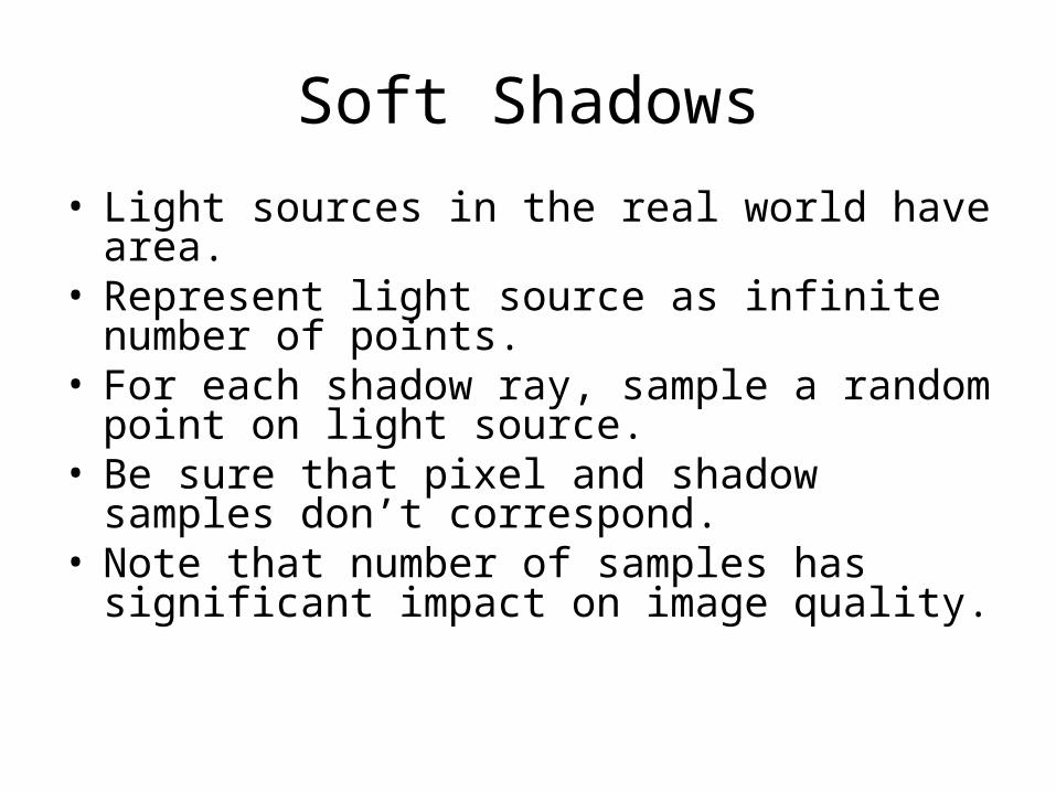
Soft Shadows
• Light sources in the real world have area.• Represent light source as infinite number of
points.• For each shadow ray, sample a random point on
light source.• Be sure that pixel and shadow samples don’t
correspond.• Note that number of samples has significant
impact on image quality.

Point light, no soft shadows
Area light, soft shadows, 16 samples/pixel
Area light, soft shadows, 64 samples/pixel
Depth of Field
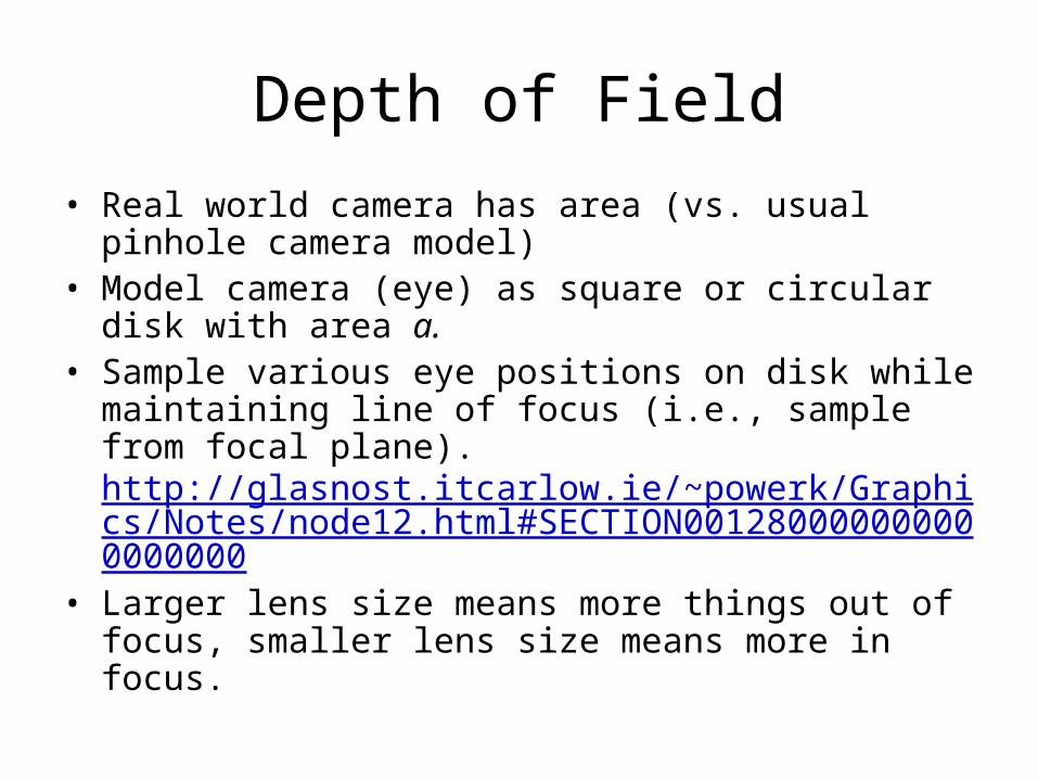
• Real world camera has area (vs. usual pinhole camera model)
• Model camera (eye) as square or circular disk with area a.
• Sample various eye positions on disk while maintaining line of focus (i.e., sample from focal plane). http://glasnost.itcarlow.ie/~powerk/Graphics/Notes/node12.html#SECTION001280000000000000000
• Larger lens size means more things out of focus, smaller lens size means more in focus.

Perfect focus Small lens size Large lens size
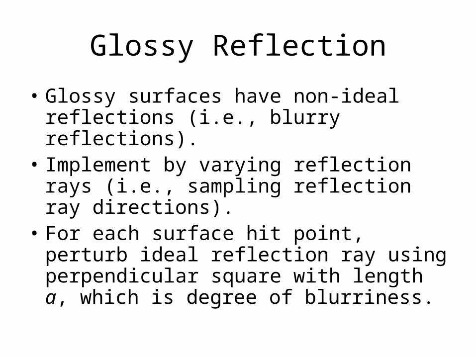
Glossy Reflection
• Glossy surfaces have non-ideal reflections (i.e., blurry reflections).
• Implement by varying reflection rays (i.e., sampling reflection ray directions).
• For each surface hit point, perturb ideal reflection ray using perpendicular square with length a, which is degree of blurriness.

Perfect reflection Glossy Reflection, 16 samples/pixel
Glossy reflection, 64 samples/pixel

Motion Blur
• Image is formed over non-zero span of time.• For each ray, pick a random time between
t_start and t_end, and intersect with moving primitive.
• Resulting image will again be blurred.• Important to specify both start and end positions
of object in order to calculate bounding boxes for ray acceleration.

T = 0 T = 5 T = 10

(1) James T.

TriangleMeshGroup & CSGs
James Tolbert, II
Assignment 10 Presentation
6.837

Triangle Mesh Group
• No new Object3D, Group subclass
• Only Override the inside Method
• Parse calls TriangleMeshGroup
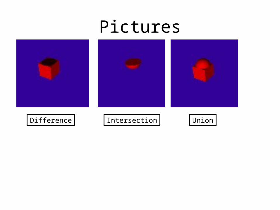
Pictures
Difference Intersection Union

CSG Plane

Some of Text File• Group {• numObjects 6
• Transform {• Translate 0 0 1• Group {• numObjects 2• Transform {• Translate 3 3 0• Scale 0.5 0.6 0.5• Group {• numObjects 4• MaterialIndex 0• Transform {• Scale 2 2 2• Group {• numObjects 1• Difference {• TriangleMesh {• obj_file cube.obj• }• Sphere {• center 0 1 0• radius 0.8• }• }• }• }•
Transform { Translate 0 5 0 Scale 1 5 1 XRotate 180 Group { numObjects 1 Intersection { TriangleMesh { obj_file cube.obj } Sphere {
center 0 1 0 radius 1
} } } } Transform { Translate 0 -5 0 Scale 1.5 4 1.5 Group { numObjects 1 Intersection { TriangleMesh { obj_file cube.obj } Sphere {
center 0 1 0 radius 1
} } } } Transform { Translate 0 2 0 Scale 1.4 0.5 1.4 XRotate 180 Group { numObjects 1 Intersection {
TriangleMesh { obj_file cube.obj } Sphere {
center 0 1 0 radius 1
} } } } }} MaterialIndex 1 Transform { Translate 3 3 4 XRotate 90 ZRotate 90 YRotate -90 Scale 1.5 0.5 3 XRotate 90 Group { numObjects 1 Intersection { TriangleMesh { obj_file cube.obj } Sphere {
center 0 1 0
radius 1 } } } }}}
MaterialIndex 3 Transform { Translate 5 -8 1 Scale 0.5 0.5 0.5
Group { numObjects 2 Transform { Scale 1 5 1 Group { numObjects 1 Intersection { TriangleMesh { obj_file cube.obj } Sphere { center 0 1 0
radius 1 } } } } Transform { Translate 0 11 0 Scale 1 5 1 XRotate 180 Group { numObjects 1 Intersection { TriangleMesh { obj_file cube.obj } Sphere { center 0 1 0
radius 1 } } } } } }
MaterialIndex 1 Transform { Translate 5 -9 0 Scale 1.2 1.5 1.2 Group {

(2) Colin W.


(3) Javier C.
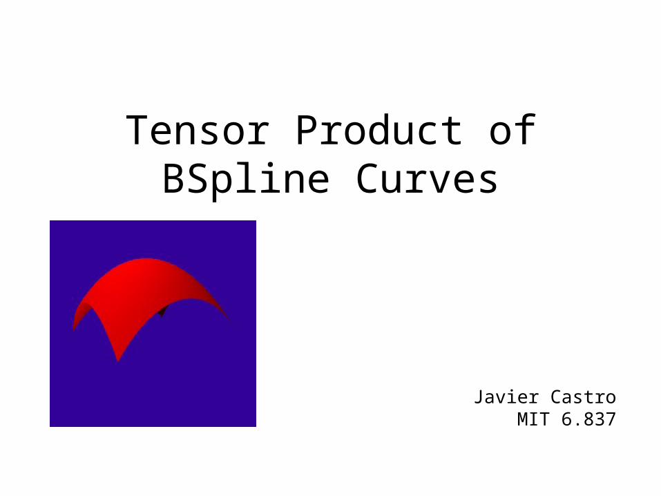
Tensor Product of BSpline Curves
Javier CastroMIT 6.837

• What is a Tensor Product?
• Definition of BSpline Patch– Can be of size M x N– Has two parameters: s and t
Definitions

Problems
• BSpline Patch vs. Bicubic Bezier Patch
• 3D Point Editing via GUI

Example

Fun with BSpline Surfaces

(4) Evelyn E.

Ray Tracing Quartic Surfaces
Evelyn Eastmond
6.837 Assignment 10

Ray-Torus Intersection
• A Torus is a quartic surface
Quadratic surface - 2 roots Quartic surface - 4 roots

Ray-Torus Intersection
• Torus equation:– f(x,y,z) = (x2 + y2 + z2 –r2 – R2)2 +4R2(z2 – r2)
– x = rox + rdx, y = roy + rdy, z = roz+rdz
• Steps– Find coefficients of quartic
• By hand (1.5 hrs….)• Online
– Solve using quartic solver• By hand?• Online!

Ray-Torus: Failed Attempt 1
• Problem: inverted coefficients

Ray-Torus: Failed Attempt 2
• Problem: false positive‘t’ values

Lessons Learned
• Solve everything by hand– geometry?
• Use online sources for reference only• Acknowledgements:
– Ray-torus equation:Max Wagner, http://emeyex.com/
– Quartic solver:Geant 4 Group, http://geant4.web.cern.ch


(5) Andy A.

Distribution Ray Tracing
Andy Arizpe6.837
December 9, 2004

Soft Shadows
• Represent light source as area rather than point.
• For each shadow calculation, send multiple rays aimed at different points on the light.
• Points near the border of the shadow region will be partially lit.
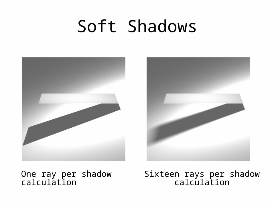
Soft Shadows
One ray per shadow calculation Sixteen rays per shadow calculation

Glossy Reflection
• Used to model materials that are somewhere between perfect mirrors and diffuse.
• For each reflection, send several rays – each one offset from the perfect mirror direction by a random vector, calculated by sampling a square perpendicular to the perfect mirror direction.
• Size of square determines amount of blurriness.

Glossy Reflection
Three spheres with glossiness values of 0, 0.25, and 0.5 (from left to right).

Depth of Field
• Extend the perspective camera with notions of lens size and distance to focus plane.
• For each pixel, shoot multiple rays originating at different points on the “lens”, but all going through the same point on the focus plane.
• With a larger lens size, objects get blurrier more quickly as you move away from focus plane.

Depth of Field
No focus – standard perspective camera
Focus on blue box
Focus on red box
(6) Ilia M.

f(r) = exp(-r2/2) f(r) = r < 1: (1-r2)2
r ≥ 1: 0

video…
PLAY VIDEO
(7) Bryan A.

EnvironmentObjects
• EnvSphere and EnvPlane• Float getDistance(Vec3f pos)• Vec3f getNormal(Vec3f pos)• Void paint()
• Each system has an array of EnvironmentObjects, so you can have several in a scene

Basic Collision Detection
For each particle
Update (using the Integrator)
For each EnvironmentObject
Calculate time of collision (-1 if no collision)
if (collision_time >= 0)
Collision response

Backtracking Collision Detection
For each particlecurr_dt = dtWhile (curr_dt >= 0)
Update (using Integrator) for curr_dtFor each EnvironmentObject Calculate first collision (if any)If collision Revert to last state (last_pos and last_vel) Update system until collision (dt - max_time) Collision responsecurr_dt = max_time
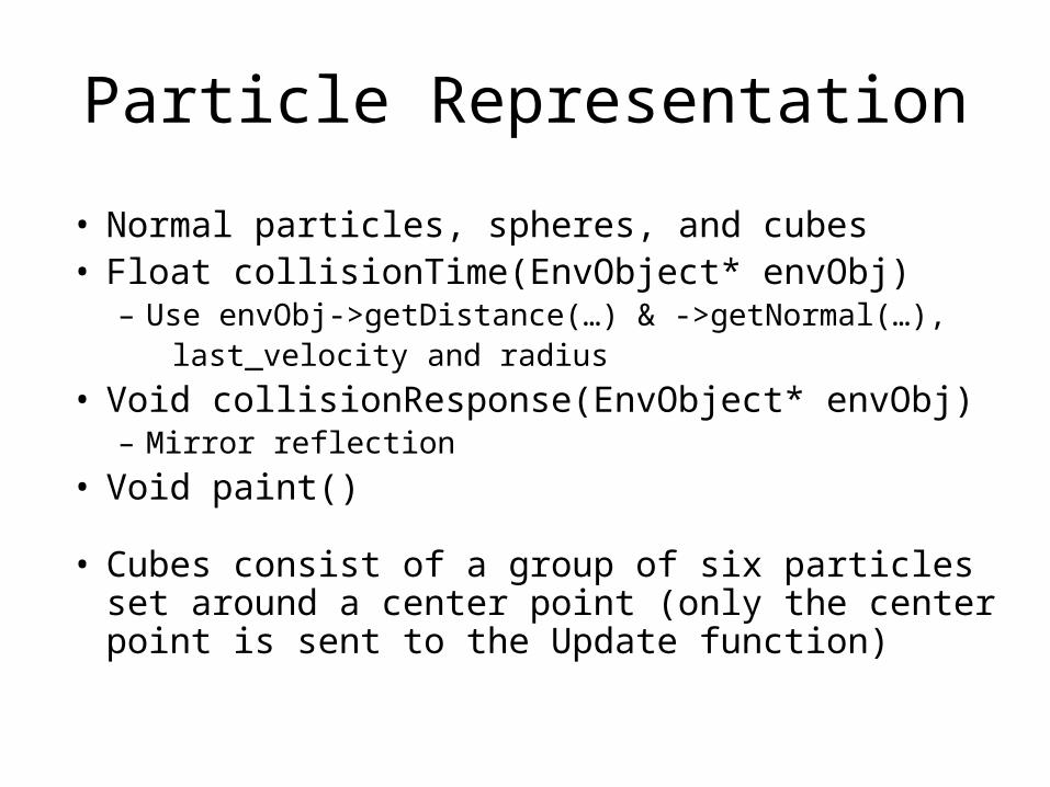
Particle Representation
• Normal particles, spheres, and cubes• Float collisionTime(EnvObject* envObj)
– Use envObj->getDistance(…) & ->getNormal(…), last_velocity and radius
• Void collisionResponse(EnvObject* envObj)– Mirror reflection
• Void paint()
• Cubes consist of a group of six particles set around a center point (only the center point is sent to the Update function)

Backtracking vs. Normal Collision Response
Normal Backtracking

Setup Environments
Cube -> 6 EnvPlanes Sphere -> 1 EnvSphere

Setup Environments (cont.)
Triangular Bar -> 5 EnvPlanes Square Pyramid -> 5 EnvPlanes
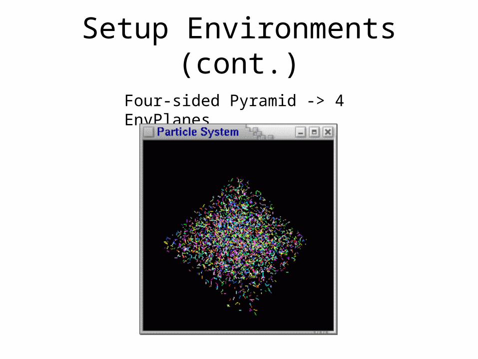
Setup Environments (cont.)
Four-sided Pyramid -> 4 EnvPlanes

Cube Pics
Cube Inside an EnvSphere Cube Inside a Cube (6 EnvPlanes)

(8) Mariana B.


(9) Kenfield G.

KENFIELD GRIFFITH


(10) Nestor H.
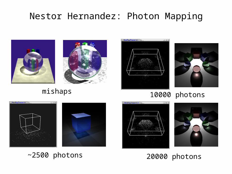
Nestor Hernandez: Photon Mapping
mishaps
~2500 photons
10000 photons
20000 photons
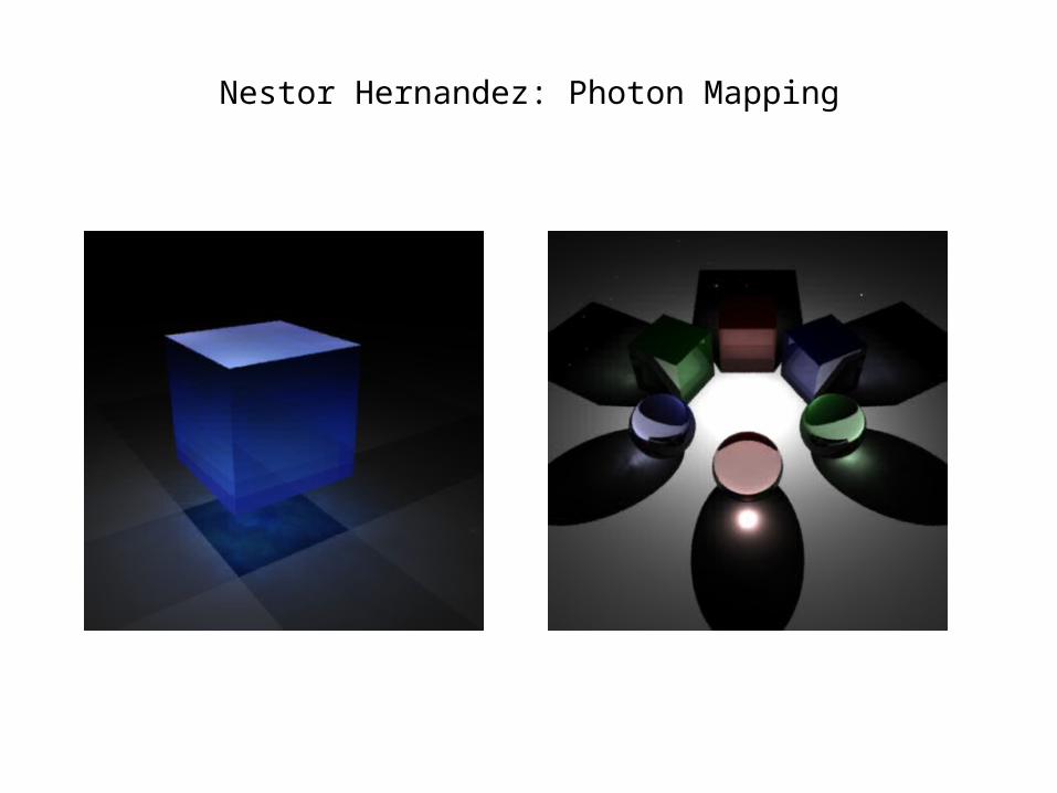
Nestor Hernandez: Photon Mapping
(11) Matthew W.

Cellular Textures
Matthew Webber

• Scale Transform
• Crack Width
• # of foci
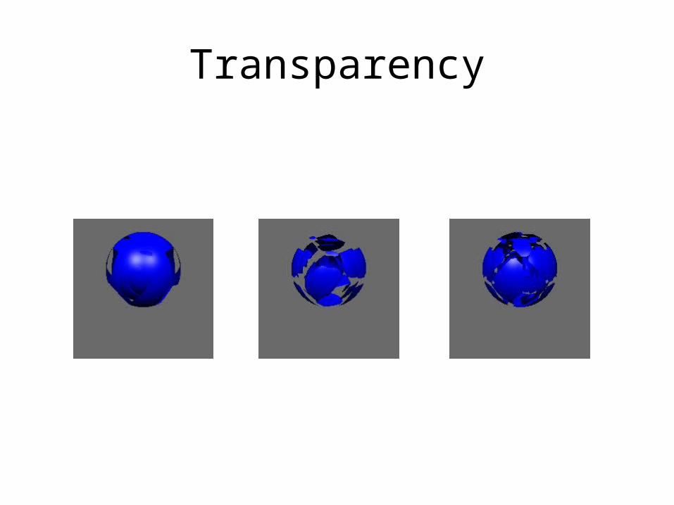
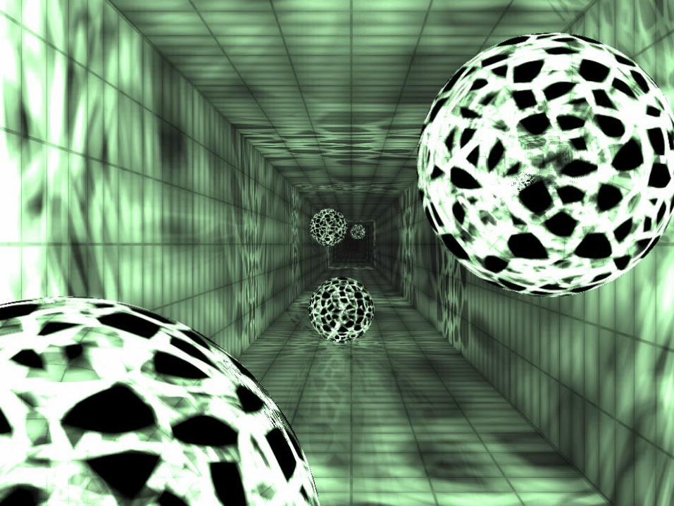
Transparency

Reflection/Refraction

Bump Mapping

Projective Shadows
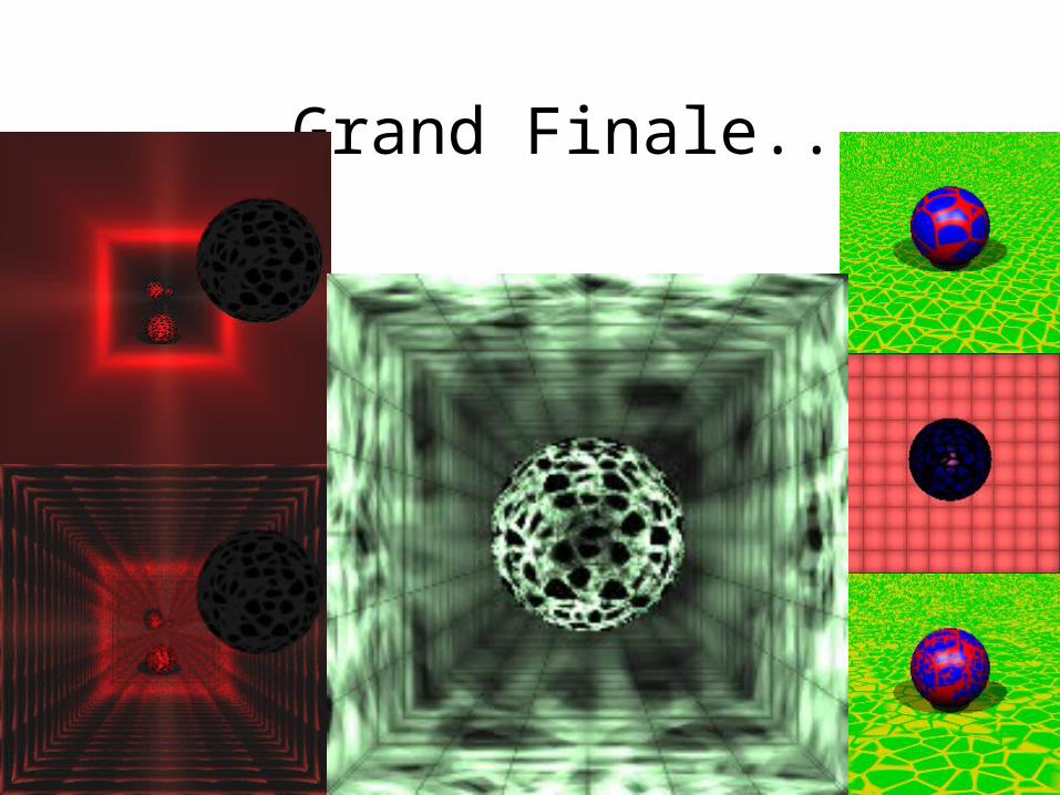
Grand Finale...
(12) Lawrie G.

Constructive Solid Geometry
• Three operations:– Union – all points in object A and all points in object B– Intersection – all points in objects A and B– Difference – all points in object A but not in object B

Constructive Solid Geometry
(13) Kevin D.

demo…
(14) Yan(James) P.

Collision Detection
6.837 Final Assignment
By Yan(James) Pang

Introduction
• Importance for physical simulation, e.g. Virtual reality, Augmented reality, etc.
• Most of objects in VR application are defined by triangle meshes
• The important collision problem is to solve the collision between two triangles
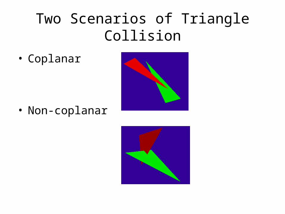
Two Scenarios of Triangle Collision
• Coplanar
• Non-coplanar

Coplanar Triangles
• Intersection– Edge-Edge Collision
• AB = A + r(B-A) • CD = C + s(D-C)• Compute r, s A + r(B-A) = C + s(D-C)• ? r, s in [0, 1]
• Inside– Vertex inside Triangle?– Optimal algorithm: reduce dimension
(3D to 2D)
• No Collision

Non-Coplanar Triangles
• Non-coplanar triangles Collision– Intersection Line (L)– Project the vertex on the Intersection Line– Compare the Projected Intervals of vertex
L
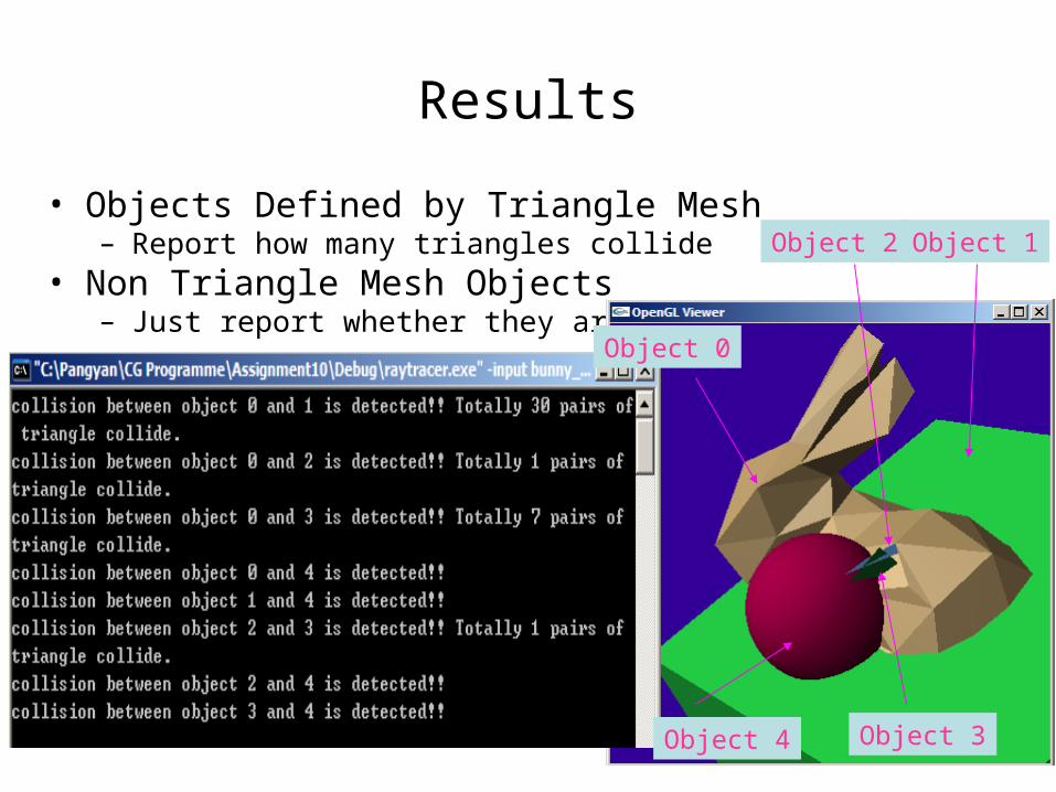
Results
• Objects Defined by Triangle Mesh – Report how many triangles collide
• Non Triangle Mesh Objects– Just report whether they are collided
Object 4 Object 3
Object 1Object 2
Object 0

(15) Emily W.

D I S T R I B U T I O N R A Y T R A C I N G
6.837E M I L Y W H I T I N G

D E P T H o f F I E L Dfocus plane + lens perturbing eye position

S O F T S H A D O W Sspherical light source

G L O S S Y R E F L E C T I O N Sperturbed reflection ray
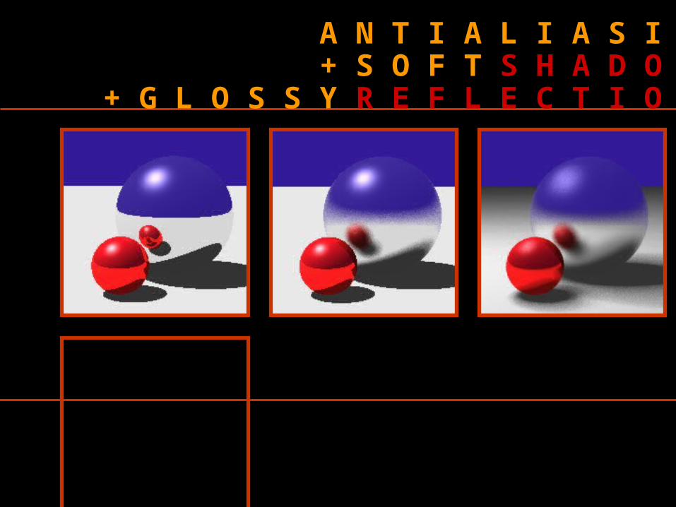
A N T I A L I A S I N G+ S O F T S H A D O W S
+ G L O S S Y R E F L E C T I O N S

(16) Dumitru D.


How do we define a surface?
• defined by a polynomial P(x, y, z) = 0
• input file:surface3d { polynomial x^2+y^2+z^2-1}

Some images
Sphere object Surface3D object: x^2+y^2+z^2-1
Transformation of a Sphere object Surface3D object: x^2+4*y^2+z^2-1

Add “cutting planes”
• Separates the space into two half-spaces
• Exactly one half-space is visible
• The normal determines which half-space is visible

More input file extensions
• Defining a surface with “cutting planes”: surface3d {
polynomial x^2+y^2+z^2-1 num_cutting_planes 2 cutting_plane { normal 0 0 -1 offset -0.7 } cutting_plane { normal 0 0 1 offset -0.7 } planes_conditions 1&2}
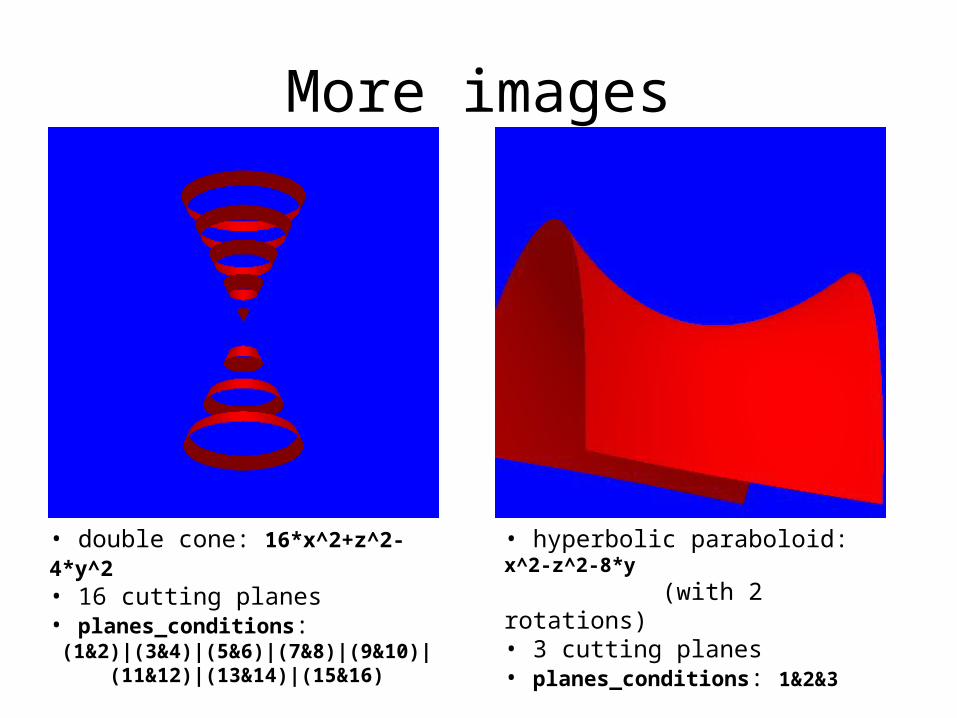
More images
• double cone: 16*x^2+z^2-4*y^2 • 16 cutting planes• planes_conditions: (1&2)|(3&4)|(5&6)|(7&8)|(9&10)| (11&12)|(13&14)|(15&16)
• hyperbolic paraboloid: x^2-z^2-8*y (with 2 rotations)• 3 cutting planes• planes_conditions: 1&2&3
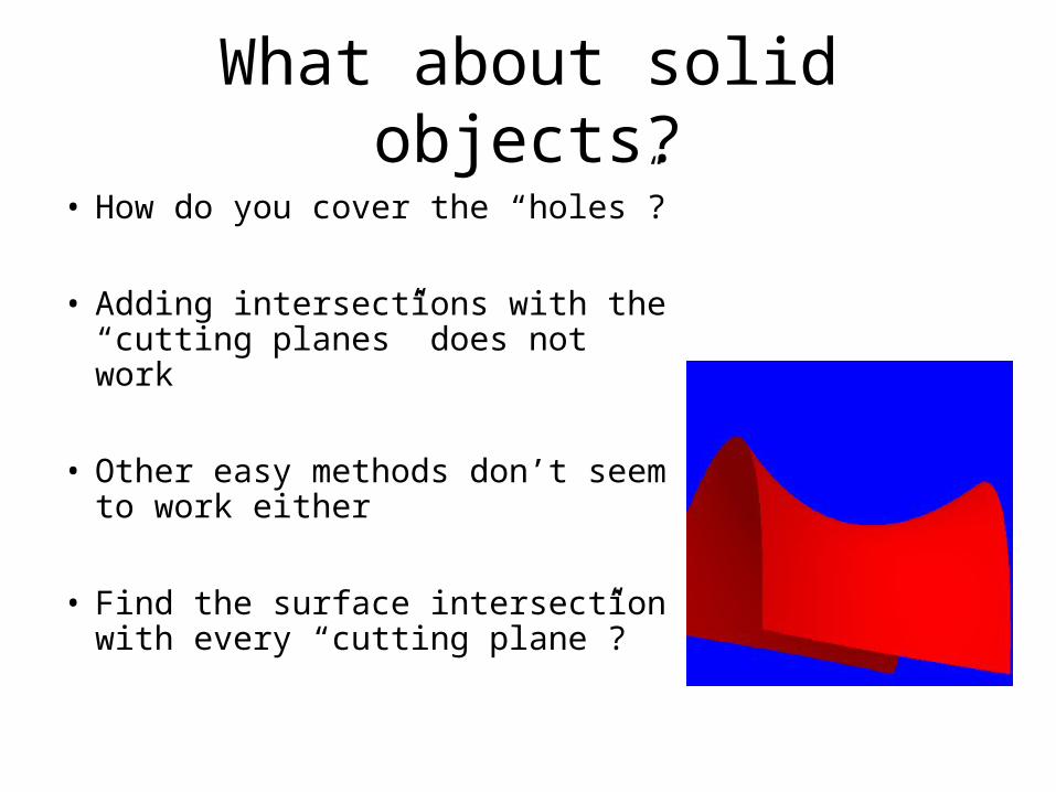
What about solid objects?
• How do you cover the “holes”?
• Adding intersections with the “cutting planes” does not work
• Other easy methods don’t seem to work either
• Find the surface intersection with every “cutting plane”?

(17) Andrew W.

demo…

(18) Diane Y.

Constructive Solid Geometry (CSG)
union intersection subtraction

How can we implement CSG?
Points on A, Outside of B
Points on B, Outside of A
Points on B, Inside of A
Points on A, Inside of B
Union Intersection Subtraction
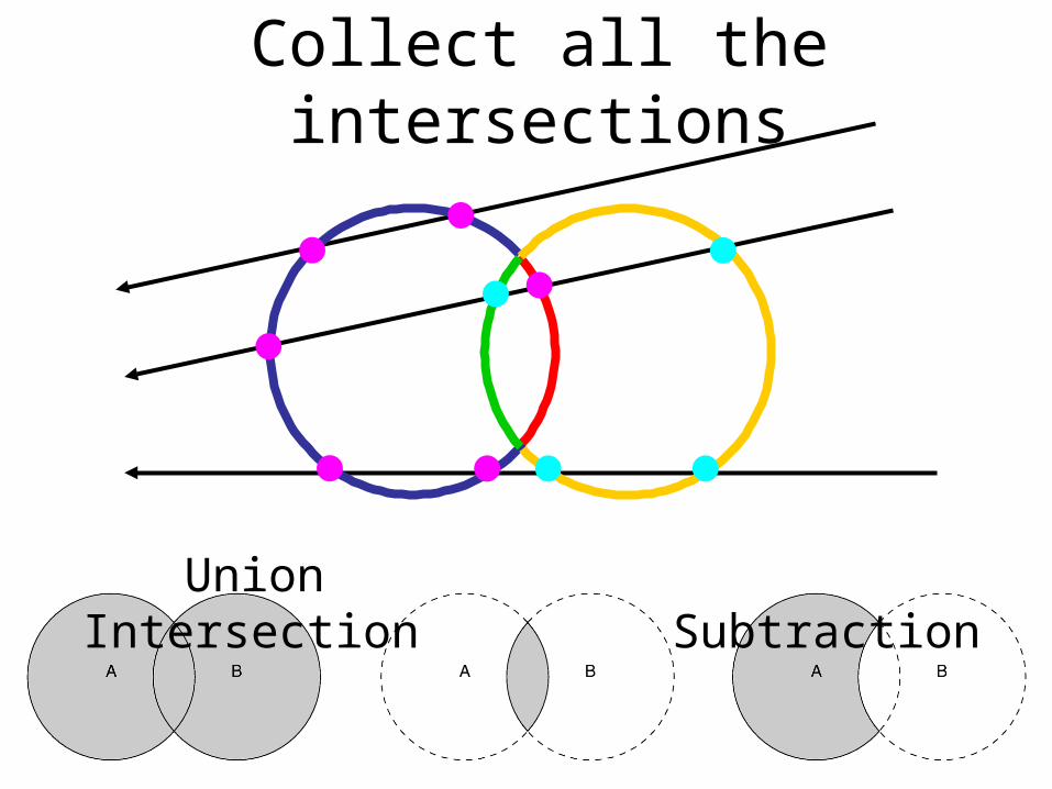
Collect all the intersections
Union Intersection Subtraction

Implementing CSG1. Test "inside" intersections:
• Find intersections with A, test if they are inside/outside B
• Find intersections with B,test if they are inside/outside A
2. Overlapping intervals:• Find the intervals of "inside"
along the ray for A and B• Compute
union/intersection/subtractionof the intervals

CSG with spheres
union intersection subtraction

CSG with triangles/planes
original intersection w/ triangles
intersection w/ plane

Nested CSG’s
Mickey
Union of 3 spheres
Saturn
Union of sphere and transform
Snowflake ball
Union of 4 transforms, intersection with sphere

A snowman

A snowman
Triangle meshes
Snowflake/plane
Triangle/sphere union
Sphere subtraction
intersection Transform/CSG union
(with noise for the sky and ground)
Sphere subtraction + triangle mesh

(19) Abraham E.

depth = 2 depth = 5
depth = 10 depth = 100


(20) Daniel W.
SUBGRIDSDaniel Wendel

-subgrid edge minD threshold maxD
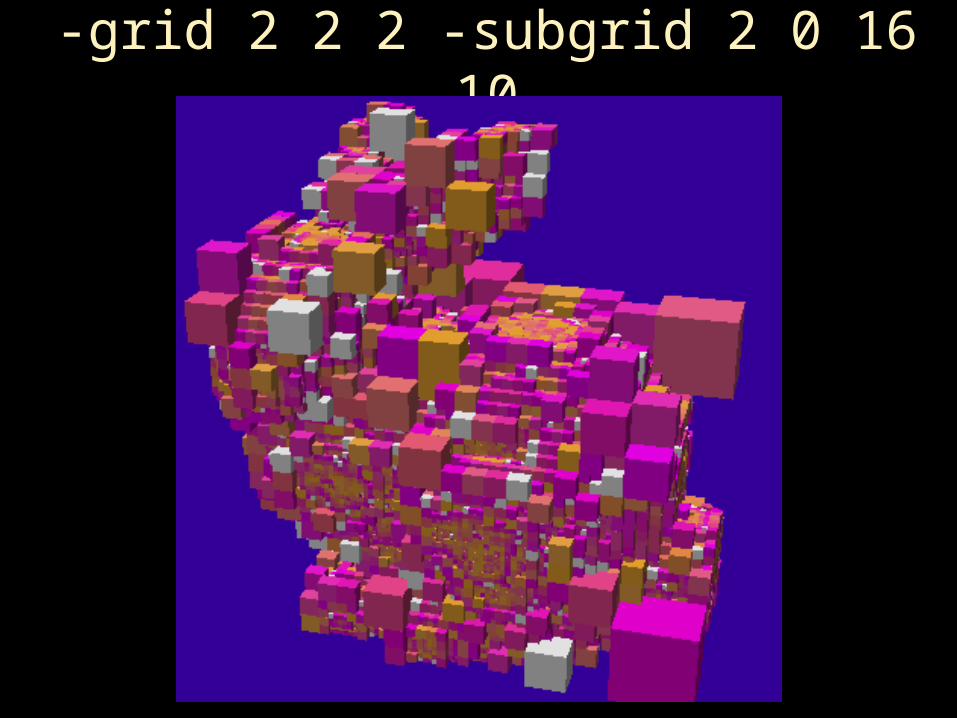
-grid 2 2 2 -subgrid 2 0 16 10

-grid 2 2 2 -subgrid 2 0 16 10

-grid 3 3 3 -subgrid 7 0 18 6

(21) Ioannis T.

demo…

(22) Emily Y.

NPR Post-Processing of Images:
Giving pictures a more personal touch
Emily Yan
December 9, 2004

What is NPR?
• NPR = Non-Photorealistic Rendering• Millions of different effects (AKA PhotoShop
filters)• Original goal: cross-hatch • Use a sawtooth pattern to
compare original grayscale
image
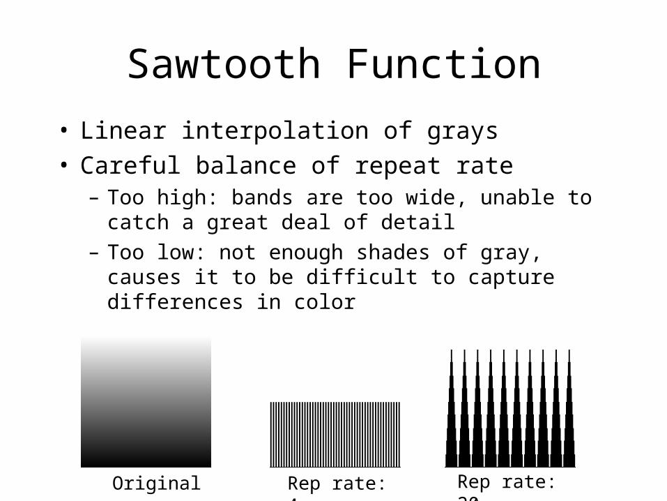
Sawtooth Function
• Linear interpolation of grays• Careful balance of repeat rate
– Too high: bands are too wide, unable to catch a great deal of detail
– Too low: not enough shades of gray, causes it to be difficult to capture differences in color
Rep rate: 4 Rep rate: 20Original

Options
• Horizontal/Vertical Bars– Slope– Scale– Offset
• Mesh
• Rings
• Stipple

Equalization Required
Sometime your pattern is just too dark…
Normal
Equalized
Pattern Output

Eye Candy
Uses mesh, equalize
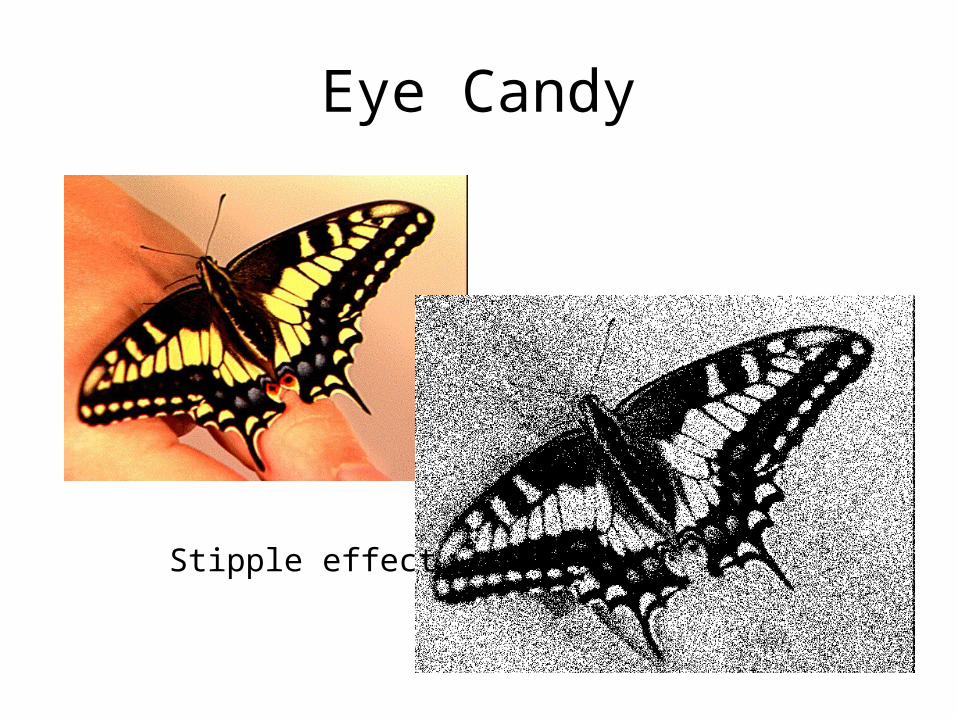
Eye Candy
Stipple effect

Eye Candy
Uses rings
(23) Tom H.

Distribution Ray Tracing Effects
Tom Hoover
6.837

Soft Shadow
• Finite sized lights• For each intersection
sample over light• Sampling over cone,
not uniform distribution

Motion Blur
• Give ability for objects to have a start and an end point
• Keep track of time during the entire ray-casting process
• For each pixel, sample over random time
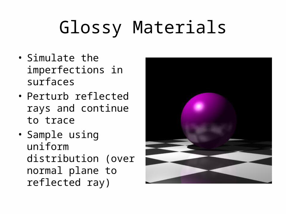
Glossy Materials
• Simulate the imperfections in surfaces
• Perturb reflected rays and continue to trace
• Sample using uniform distribution (over normal plane to reflected ray)

(24) Eric L.


(25) Rohit R.
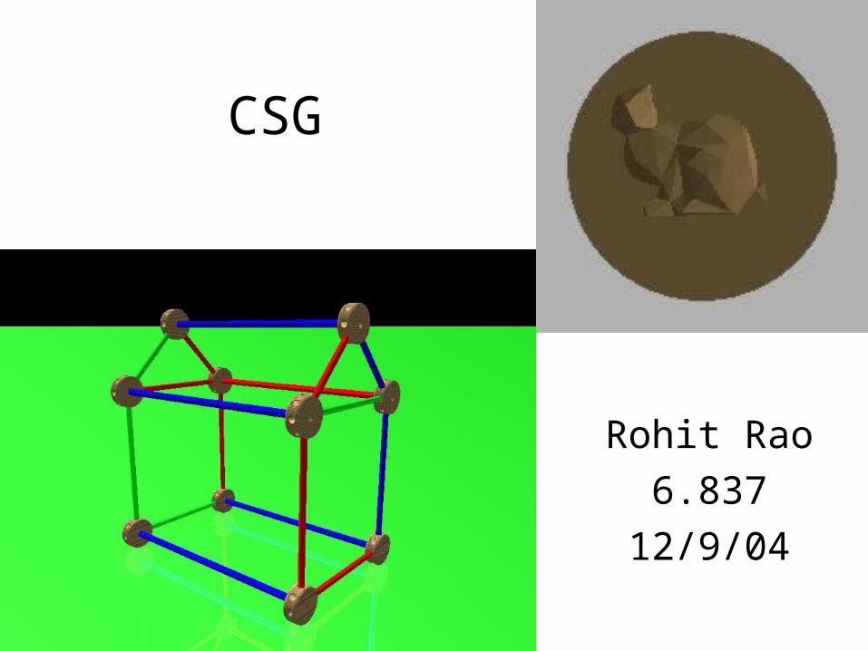
CSG
Rohit Rao
6.837
12/9/04

CSG Operations

Tinkertoys

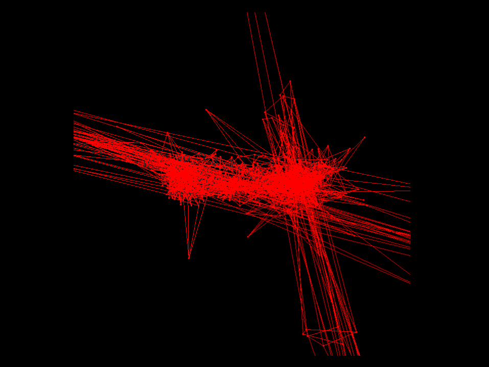
Why my CSG sucks
• Scenes get very complex, very fast– Tinkertoy house was ~2000 lines
• Can’t really use grid acceleration– Difference(40k bunny, cylinder)

Grid Acceleration
• Solution: put the Grid inside the CSG object


(26) Annie D.

Lighting Stained Glass Texture Mapping
Transparent ShadowsVolumetric Raytracing
Annie DingDecember, 2004

Texture Mapping
• Map coordinates from bitmap image onto primitives

Transparent Shadows
• Extension of assignment 4• Accumulate transparent color as
shadow ray passes through objects

Volumetric Raytracing
• Dust/smoky effect - to show light rays
• Incrementally step along the rays cast, shooting additional rays towards the light sources – Accumulate color over the ray by
using exponential function: e^Density*step_length

Eye Candy

Eye Candy

Eye Candy

(27) Jim G.

Sphere Texture Mapping

Triangle Texture Mapping

Bump Mapping

(28) Mike M.

Animated Water and
Caustics
Michael MatczynskiDecember 9, 2004

Pass 1: Photon Tracing
• Create photons from PhotonSources
• Trace photons through the scene using tracePhoton()
• When a photon hits a diffuse surface, store it in PhotonMap
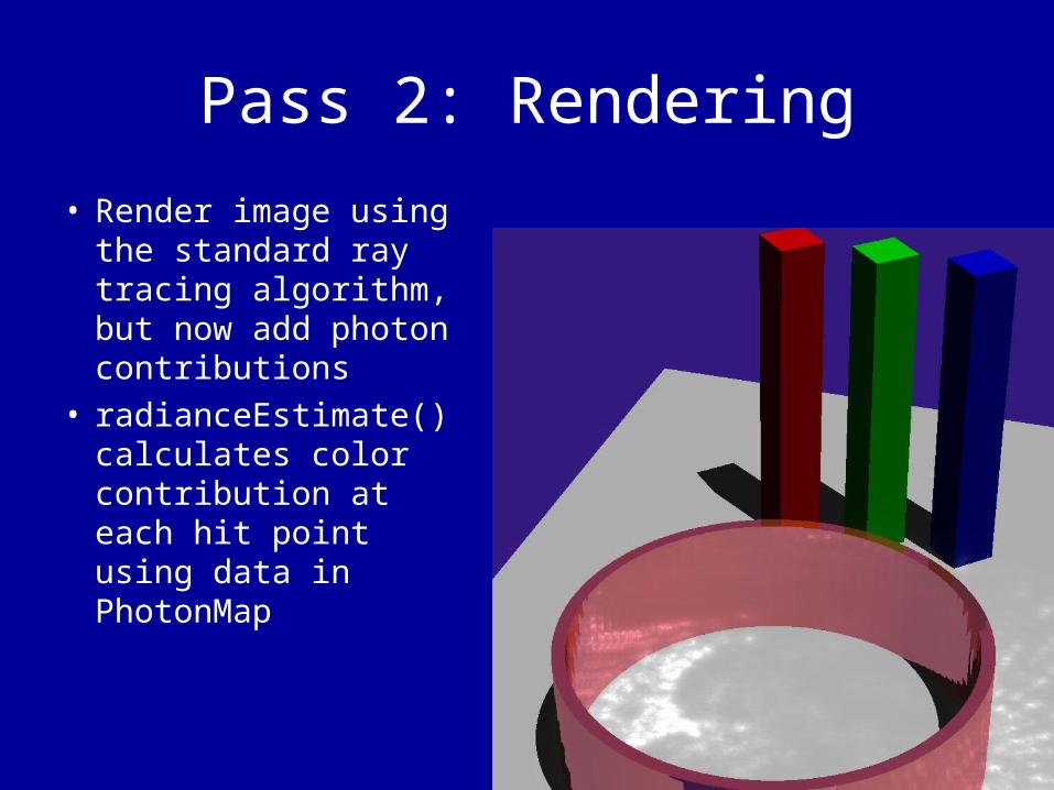
Pass 2: Rendering
• Render image using the standard ray tracing algorithm, but now add photon contributions
• radianceEstimate() calculates color contribution at each hit point using data in PhotonMap

Animated Water Demo
• Animate.exe creates a sequence of frames simulating water waves
• 1000 photons / 10 samples per pixel
• 24 frames• 20 minutes on 6
Xeon 2.0ghz workstations
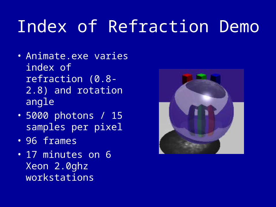
Index of Refraction Demo
• Animate.exe varies index of refraction (0.8-2.8) and rotation angle
• 5000 photons / 15 samples per pixel
• 96 frames• 17 minutes on 6
Xeon 2.0ghz workstations

The EndGreat Job Everyone!