672 radiation performance and specific absorption rate ...braaten/eit2015-171.pdf · radiation...
TRANSCRIPT

Radiation Performance and Specific AbsorptionRate (SAR) Analysis of a Compact Dual Band
Balanced AntennaAdnan Iftikhar, Muhammad M. Masud,
Muhammad N. Rafiq,Sajid Asif and Benjamin D. Braaten
Department of Electrical and Computer EngineeringNorth Dakota State University
Fargo, ND, USA 58102Email: [email protected]
Muhammad Saeed KhanDepartment of Information Engineering
University of PadovaVia Gradenigo 6/b. 35131 Padova, Italy
Email: [email protected]
Abstract—This paper presents a compact dual-band dipoleantenna with meander line radiating elements. The proposedantenna has a balanced structure with dimensions of 35×6×1.52mm3, and mounted on a 36.2 × 100 mm2 floating groundplane. The balanced operation of the design is validated byincorporating a differential feed in the software simulation anda 180 ◦ hybrid junction is used for measurement with thenetwork analyzer to verify the balanced concept of the prototype.Simulated and measured results of the S-parameters along withthe de-tuning of the antenna in the presence of the human bodyshows good agreement. Moreover the proposed design is usedas an exposure source to the simulated human head model. Thehuman head is modeled as six layers in the Electromagnetic (EM)software HFSS to study the interaction between the proposedbalanced antenna and the human head model. The Electric field(E-field) distribution in the six layers of the human head model isshown to estimate the penetration of the field when the antenna isplaced at a distance of 7 mm from the proposed design. Also LocalSpecific Absorption Rates (SARs) and average SARs simulationresults at 3.78 GHz and 4.29 GHz are shown. The SARs analysisshowed that in all the six layers of the human head model, localSAR values are greater in fat and Cerebrospinal fluid (CSF) forboth the frequencies while the average SAR values are not veryhigh.
Index Terms—Balanced antenna, Electromagnetic Interference(EMI).
I. INTRODUCTION
Printed antennas are used in wireless devices such ascellular phones, cordless, wireless LAN Access points, GPShandheld devices, Personal digital assistants (PDAs), and Pub-lic switched telephone network (PSTN) series [1]. These patchantennas are not only miniature in size but also manufacturedusing simple and cost effective techniques [2], [3]. However,radiating currents can be induced on the ground planes ofthese antennas when they are being used in the devices heldby users. This is because the ground planes of these antennasare in direct contact with the human hand/head that resultsin current flow in the body, which degrades the antenna per-formance, introduces mismatching, affect Specific Absorption
Rates (SARs) and E-field penetration strength. Thus the mainobjective of this work is to consider a new balanced antennadesign that is effected minimally by the presence of the user[4]. This phenomenon gives the main advantage of havingalmost negligible EMI with the human body. Moreover, themaximum SAR of these antennas are likely to be reducedwhen placed next to the user’s head [5]. Antennas similar todipoles are symmetric in nature and become balanced whenfed with a differential source.
These balanced structures are a good choice for the PDAapplications because of their property to mitigate the degra-dation caused by the human body and reduced SAR effect.Furthermore, current in the ground plane is remarkably re-duced because of the differential current flow in the dipoleantenna arms [6]. This also helps in the reduction of EMIcaused by the integration of other electronic devices on theground plane. The probable biological effects of the EM fieldwith printed antennas using the HFSS equivalent head modelshave been reported in [7], [8], thus confirms the validation ofthese human head models for the evaluation of SARs valuesand E-field strengths.
In this paper the balanced antenna design is presented usinga meandered type structure which reduces the physical sizeof the antenna. HFSS v. 13.0 [9] is used for the simulationof the design and optimization of the antenna dimensions atresonant bands. Moreover the equivalent six layer human headis modeled in HFSS using the dielectric properties of the headtissues given in [10]. The E-field strength in all six layers ofthe human head tissue is presented along with the SAR ofthe human head in the presence of the proposed dual-bandbalanced antenna.
II. ANTENNA DESIGN PROCEDURE, STRUCTURE ANDHEAD EQUIVALENT MODEL
The proposed balanced antenna structure on a RogersTMM4 substrate with ϵr=4.2 and a thickness of 1.52 mm isshown in Fig. 1(a). The geometry of the proposed antenna
672
978-1-4799-8802-0/15/$31.00 ©2015 IEEE

f
h a
k
gap
jb
ic
y x
d
g
xxy
z
(b)
e
l
(a)
Feed point
Patch Ground plane
Substrate
L
H
W
Fig. 1. (a). Configuration of proposed Microstrip Dipole antenna with L=100mm, W=36.2 mm and H=6 mm. (b). Proposed Balanced antenna (a =1.4 mm,b=1.3 mm, c=0.7 mm, d=16.3 mm, e=4 mm, f=1.3 mm, g=9 mm, h=7.85mm, i=2.2 mm, j=2.6 mm, k=1.2 mm, l=0.3 mm, x=3.4 mm, y=11 mm andgap=0.2 mm).
3.5 4 4.5 5 5.5
-50
-40
-30
-20
-10
0
f (GHz)
|S1
1| (
dB
)
Variation for a=1.4mm & f=1.3mmVariation for a=1.2mm & f=1.3mmVariation for b=0.3mm & g=9.3mmVariation for c=0.9mm & h=8.85mmVariation for d=16.3mm & k=1.4mm Variation for g=11.3mm & d=17mm
Fig. 2. Parametric Analysis.
with detailed dimensions is shown in Fig. 1(b). The antennais fed using a coaxial line. Each arm of the proposed antennacontains three branches (y, g, and d), as shown in Fig. 1(b),while two extended branches (x, and h) elongating from themain strip (y) are responsible for the resonance at the requirebands. Changing the length and width of these strips results inthe shifting of the resonant bands. An extensive study of theproposed design shows that the length (a, b, c, d, e, f , g, h,and k) and width (i, b, and k) of the strips are responsible forthe different resonant bands. The variation in length and widthof the strips provide discontinuity in the current path also. Aparametric analysis of the variations are shown in Fig. 2. Itwas noticed that introducing more meandered lines results inmore resonant bands.
Brain
(a) (b)
CSF
Dura
BoneSkin
Fat
Simulated
Head Model
AntennaGround
Plane
Feed
Fig. 3. (a). Six-Layer Equivalent Head Model (Side View) (b).ProposedDesign as exposure source to the Head Model
radiating patch
Ground Plane
Fig. 4. Balanced antenna prototype.
Furthermore, the equivalent model of the human head withSkin, Fat, Bone, Dura, and Cerebrospinal Fluid (CSF) ismodeled in the HFSS, as shown in Fig. 3(a). The thickness,mass densities of these six layer [8] and dielectric properties[10] of the human head tissues at 3.78 Ghz and 4.29 Ghz areused for defining all the six layers. In order to estimate theSARs value and E-field strength, the proposed antenna is usedas the exposure source of an input power of 1W, as shown inFig. 3(b).
III. RESULTS AND DISCUSSION
The design with the optimized values (listed in Fig. 1(b))was fabricated next and is shown in Fig. 4. The balancedantenna performance was measured in terms of its returnloss by placing the design in isolation mode, with humanhand alone, and with human head and hand both. Theseparameters were validated using HFSS and the S-Parameterswere measured in a chamber using the network analyzer. Fig.5 shows the measured and simulated results of the proposeddesign without using a balun [11] in the presence of the humanhand and head. The antenna resonates at 3.78 GHz and 4.29GHz with bandwidths of 80 MHz and 100 MHz, respectively.The balanced operation of the design was verified using abalun by measuring the S11 parameters in isolation mode andin the presence of the human head and hand, as illustrated inFig. 6. The return loss is 25 dB at 3.78 GHz and 18 dB at 4.29GHz. It was observed that there was lesser degradation in the|S11| parameters of the antenna in all positions, showing theadvantage of using a balanced design. The current distribution
673

3.5 3.75 4 4.25 4.5
−30
−25
−20
−15
−10
−5
0
f (GHz)
S11 (dB)
S11 Measured
S11 Simulated
S11 measured with Hand
S11 measured with Hand
and Head
Fig. 5. S-parameters of the antenna without using Balun
3.5 3.75 4 4.25 4.5
−50
−40
−30
−20
−10
0
f (GHz)
S11 (dB)
S11 isolation mode
S11 with hand
S11 with hand and head
Fig. 6. S-Parameters of antenna using Balun.
1.7 e+02
4.1 e+01
9.6 e+00
2.2 e+00
1.4 e -01
3.2 e -01
5.2 e -01
2.0 e -01
Jsurf [A/m]
1.7 e+02
4.1 e+01
9.6 e+00
2.2 e+00
1.4 e -01
3.2 e -01
5.2 e -01
2.0 e -01
Jsurf [A/m]
1.7 e+02
4.1 e+01
9.6 e+00
2.2 e+00
1.4 e -01
3.2 e -01
5.2 e -01
2.0 e -01
Jsurf [A/m]
(a)
(b)
(c)
Zero phase between
feed lines
180 phase between
feed lines
0
Fig. 7. Simulated ground plane current at 3.78 GHz for (a) Balancedantenna with zero phase (d) Balanced antenna with differential phase and(c) Unbalanced antenna. (similar results were observed at 4.29 GHz for a, b,and c)
E-�Field�(V_per_m)
1.2621e+002
1.0677e+002
9.9156e+001
9.1547e+001
8.3937e+001
6.8717e+001
6.1108e+001
3.0669e+001
2.3059e+001
1.5449e+001
7.8397e+000
2.30000e-001
Fig. 8. E-field strength in the Skin tissue at 4.29 GHz
SAR�Field�(W/Kg)
4.0506e-001
3.6755e-001
3.1932e-001
2.9520e-001
2.2285e-001
1.7462e-001
1.5051e-001
7.8159e-002
5.4043e-002
2.9927e-002
5.8112e-003
Fig. 9. Average SAR value of the Skin tissue at 4.29 GHz.
on the ground plane of the proposed antenna was simulatedfor the design with the in-phase feed currents, balanced designwith the differential feed and the unbalanced design . It isshown in the Fig. 7 that the current distribution on the groundplane for the proposed balanced antenna is much lower thanthe unbalanced design and in-phase feed line. It is shown thatwith the balanced antenna design approach, the ground planecurrents can be minimized, thus reducing the human bodyeffects on the antenna performance, reduced SAR effect andE-field penetration strength in the human head.
Next, the E-field strength in the skin tissue at 4.29GHzis shown in the Fig. 8. The E-field strength is maximumat the nearest point of the proposed balanced antenna andhas a minimum value away from the exposure source. Fig. 9shows the average SAR value of the skin tissue because of theproposed balanced design. It was observed that the maximumaverage SAR value is 0.405 W/kg which is less than the USSAR Limit of 1.6 W/Kg.
Table I summarizes the local and average SAR values ofthe human head tissues. It is shown that at 3.78 GHz, themost affected tissues are fat tissue and the CSF tissue. Thisis because of the SAR dependence of these simulations onthe layer distance and conductivity of the respective tissues,whereas in the rest of the tissues the local SAR value is less
674
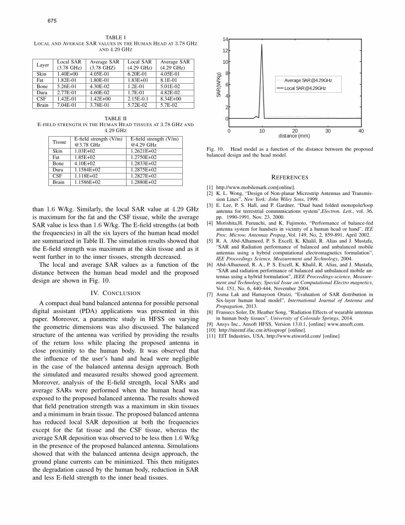
TABLE ILOCAL AND AVERAGE SAR VALUES IN THE HUMAN HEAD AT 3.78 GHZ
AND 4.29 GHZ
Layer Local SAR(3.78 GHz)
Average SAR(3.78 GHZ)
Local SAR(4.29 GHz)
Average SAR(4.29 GHz)
Skin 1.40E+00 4.05E-01 6.20E-01 4.05E-01Fat 1.82E-01 1.80E-01 1.83E+01 8.1E-01Bone 5.26E-01 4.30E-02 1.2E-01 5.01E-02Dura 2.77E-01 4.60E-02 1.7E-01 4.82E-02CSF 1.42E-01 1.42E+00 2.15E-0.1 8.34E+00Brain 7.04E-01 3.78E-01 5.72E-02 5.7E-02
TABLE IIE-FIELD STRENGTH IN THE HUMAN HEAD TISSUES AT 3.78 GHZ AND
4.29 GHZ
Tissue E-field strength (V/m)@3.78 GHz
E-field strength (V/m)@4.29 GHz
Skin 1.03E+02 1.2621E+02Fat 1.85E+02 1.2750E+02Bone 4.10E+02 1.2833E+02Dura 1.1584E+02 1.2875E+02CSF 1.118E+02 1.2827E+02Brain 1.1586E+02 1.2880E+02
than 1.6 W/kg. Similarly, the local SAR value at 4.29 GHzis maximum for the fat and the CSF tissue, while the averageSAR value is less than 1.6 W/kg. The E-field strengths (at boththe frequencies) in all the six layers of the human head modelare summarized in Table II. The simulation results showed thatthe E-field strength was maximum at the skin tissue and as itwent further in to the inner tissues, strength decreased.
The local and average SAR values as a function of thedistance between the human head model and the proposeddesign are shown in Fig. 10.
IV. CONCLUSION
A compact dual band balanced antenna for possible personaldigital assistant (PDA) applications was presented in thispaper. Moreover, a parametric study in HFSS on varyingthe geometric dimensions was also discussed. The balancedstructure of the antenna was verified by providing the resultsof the return loss while placing the proposed antenna inclose proximity to the human body. It was observed thatthe influence of the user’s hand and head were negligiblein the case of the balanced antenna design approach. Boththe simulated and measured results showed good agreement.Moreover, analysis of the E-field strength, local SARs andaverage SARs were performed when the human head wasexposed to the proposed balanced antenna. The results showedthat field penetration strength was a maximum in skin tissuesand a minimum in brain tissue. The proposed balanced antennahas reduced local SAR deposition at both the frequenciesexcept for the fat tissue and the CSF tissue, whereas theaverage SAR deposition was observed to be less then 1.6 W/kgin the presence of the proposed balanced antenna. Simulationsshowed that with the balanced antenna design approach, theground plane currents can be minimized. This then mitigatesthe degradation caused by the human body, reduction in SARand less E-field strength to the inner head tissues.
0 10 20 30 40
0
2
4
6
8
10
12
14
distance (mm)
SAR
(W/K
g)
Average SAR @ 4.29GHz
Local SAR @ 4.29GHz
Fig. 10. Head model as a function of the distance between the proposedbalanced design and the head model.
REFERENCES
[1] http://www.mobilemark.com[online].[2] K. L. Wong, “Design of Non-planar Microstrip Antennas and Transmis-
sion Lines”, New York: John Wiley Sons, 1999.[3] E. Lee, P. S. Hall, and P. Gardner, “Dual band folded monopole/loop
antenna for terrestrial communications system”,Electron. Lett., vol. 36,pp. 1990-1991, Nov. 23, 2000.
[4] Morishita,H. Furuuchi, and K. Fujimoto, “Performance of balance-fedantenna system for handsets in vicinity of a human head or hand”, IEEProc. Microw. Antennas Propag.,Vol. 149, No, 2, 859-891, April 2002.
[5] R. A. Abd-Alhameed, P. S. Excell, K. Khalil, R. Alias and J. Mustafa,“SAR and Radiation performance of balanced and unbalanced mobileantennas using a hybrid computational electromagnetics formulation”,IEE Proceedings Science, Measurement and Technology, 2004.
[6] Abd-Alhameed, R. A., P. S. Excell, K. Khalil, R. Alias, and J. Mustafa,“SAR and radiation performance of balanced and unbalanced mobile an-tennas using a hybrid formulation”, IEEE Proceedings-science, Measure-ment and Technology, Special Issue on Computational Electro magnetics,Vol. 151, No. 6, 440-444, November 2004.
[7] Asma Lak and Hamayoon Oraizi, “Evaluation of SAR distribution inSix-layer human head model”, International Journal of Antenna andPropagation, 2013.
[8] Fransecs Soler, Dr. Heather Song, “Radiation Effects of wearable antennasin human body tissues”, University of Colorado Springs, 2014.
[9] Ansys Inc., Ansoft HFSS, Version 13.0.1, [online] www.ansoft.com.[10] http://niremf.ifac.cnr.it/tissprop/ [online].[11] EIT Industries, USA, http://www.etiworld.com/ [online]
675