667 manual work copy
TRANSCRIPT

OPERATION MANUAL

Congratulations on the purchase of your new RANDALL MODEL 667 Amplifier! We at Randall Amplification appreciate that you chose the 667 Amplifier and wish you years with tons of gain, great tone and enjoyable playing time. Engineered by world renowned amp guru, Mike Fortin, this amplifier is the result of countless hours of listening tweaking and perfecting the tight and relentless attack that this collection of channel circuits deliver. The design is intended to offer the most flexible tube amplifier ever created. With 6 channels, 6 modes per channel and 7 midi assignable functions, the 6-6-7 takes high gain to the highest levels!!!Please review the safety instructions below and be aware that the documentation provided in this manual references 120volt USA versions of the models covered.
Note that the POWER listed on the back of the unit should be for your countries’ power standard.
Front and Rear Controls

!
!
!
CHx: Selects your channel and GAINx , BRIGHT switch, and VOLx.GAINx: Overall gain control.BRIGHT: 3 way high frequency boost that becomes less active as GAINx control is increased.VOLx: Channel volume control to balance output between other channels. It affects the SEND levels of the FX LOOP.
TSS: 3 way switch that shifts the frequency point of the tone stack to better match the amplifier to different speaker types and room sizes.
BASS: Passive interactive low frequency equalization for CHx.MIDDLE: Passive interactive midrange frequency equalization for CHx.TREBLE: Passive interactive high frequency equalization for CHx.
DEPTH: Power amp control of low frequency interaction between amplifier and speakers. Dedicated to row of controls for CHx selected.
PRESENCE: Power amp control of high frequency variable feedback. Dedicated to row of controls for CHx selected.
TIPS: For the Clean Channels 1 and 2, obviously keeping the gains lower and bringing up the channel volumes will yield the clean tones and vice versa for dirty tones. For channels 3 to 6, make sure to have the channel volumes 2-3 o'clock or more to have the correct amount of body on the tone. Then just make the channel volume adjustments to balance the loudness between the channels. All the channel volumes are pre FX loop so after you balance all the loudness levels between all the channels, you only have to set your loop up once. After that when going to gigs or rehearsals, only the overall master volumes have to be adjusted as everything else stays as is.
Six Channels of Pre-amp - overview:!

MIDI Programmable Functions & Masters:!
Channel 1&2 overall voicing is American 60's era. Channels 3&4 overall voicing is 70&80's rock with a heavy dose of thick juicy midrange. Channels 5&6 overall voicing is 90's+ modern voicing with more growl, gain, and sparkle.
BOOST: A preset gain boost for all channels. BOOST function works in all modes of Channel 1 and 2. BOOST button will light but will not function in channels 3-6 only in the VOICING L mode.
VOICING L: For Channels 1 & 2, there is always 3 stages of tube gain to keep the harmonic content, voicing L scoops out the mids. For Channels 3 & 4 / 5 & 6. Selects 2-12AX7 preamp gain stages. This is excellent for players that love that wide open, late 60’s vibe. This is the lowest gain setting of the 667. The BOOST switch is inactive in this mode. With the GAIN control setting at 11 o’clock and lower, in conjunction with MASTER volume set beyond 2 o’clock, will give you some stellar clean tones with loads of dynamics. The 3 way BRIGHT switch engages a treble boost and the amount is dependent on the GAIN control setting. Higher settings of the GAIN control, less effect the BRIGHT switch will have and the opposite with lower GAIN control settings. For a great plexi type of tone, set the MASTER completely open in the clockwise position, set the GAIN control at 2 o’clock, BRIGHT switch ON, tone stack as desired, Depth off and Presence at 1 o’clock.
VOICING M: For Channels 1 & 2, there is always 3 stages of tube gain to keep the harmonic content, voicing M bumps up the mids. For Channels 3 & 4 / 5 & 6, Selects 3-12AX7 preamp gain stages. This setting gets into some overdriven tone while still remaining very open sounding. Placing the BOOST switch ON adds more gain and girth to the tone. The 3 way BRIGHT switch functions the same as described above but now with the added tube stage, the upper harmonic quality has shifted. Varying the GAIN control will give you different degrees of attack and sharpness to the tone. Place the BRIGHT switch center off and the tone gets rounder and warmer sounding that stays even with the movement of the GAIN control. Higher settings of the GAIN control will give you more distortion and sustain. It will have enough gain for most lead work with a nice balance of punchy percussiveness. This setting also cleans up nicely when you roll back your guitar’s volume.
VOICING H: For Channels 1 & 2, there is always 3 stages of tube gain to keep the harmonic content, voicing H bumps up the mids as well as gain. For Channels 3 & 4 / 5 & 6, Selects 4-12AX7 preamp gain stages. This setting gets you into the soaring modern high gain tones. Placing the BOOST switch on adds even more gain and thickness. The 3 way BRIGHT switch adds the cut and teeth to the tone and as stated above, is dependent on the GAIN control setting. Higher settings of the GAIN control with the BOOST and BRIGHT switch ON, will bring in a singing lead tone with the perfect balance of compression without losing note definition.
FX: Engages FX Loop 1 on the back panel. Loop 2 is not active.
LOOP 2: FX and LOOP 2 button must be selected to engage FX Loop 2 on the back panel. Loop 1 is not active.
MASTER 2: Master 1 is the default overall Master. MASTER 2 engages the 2nd Master Volume.
STORE: After a MIDI PC or CC has been sent to the MIDI IN jack via a controller or other MIDI device.
Push and hold down the STORE button until it blinks 3 times to store all of your changes.
STANDBY: Breaks the output tubes cathodes only. Preamp and Loops are still functioning.
POWER: On/off for the mains! !

SERIES FX LOOP: This basically works as an insert patch point. The SEND jack plugs into the effects unit’s input jack. The RETURN jack plugs into the effects unit’s output jack. The audio path of the amplifier is interrupted and 100% of the signal is being sent to the SEND jack. It must be noted that when nothing is plugged into the SERIES selected FX LOOP and the FX switch is in the on, no sound will be heard out of the speakers. You must complete the audio path with an effects unit or patched instrument cable. The S.LEVELx control is used to adjust the amount of signal being sent to an effects unit. With stomp box pedals there are usually no input level indicators. In this case you will have to use your ears to set the S.LEVELx. Set the S.LEVELx up to the maximum setting just before you start to hear the undesirable front end clipping of your effects pedal. This setting of the S.LEVELx will usually be quite low for pedals. Setting the S.LEVELx for rack units is easier since they have input indicators. You will have to experiment with your rack effects to obtain the best signal to noise ratio by trying different S.LEVELx & R.LEVELx settings in conjunction with the input & output level controls of your rack effects unit. On the R.LEVELx control, bring this up to match the signal level when the FX LOOP switch is turned off via FX switch on front panel or when the effects pedal is turned off. Toggle back and forth to set levels. PARALLEL FX LOOP: This works as a side chain. Your original, dry tone is unaffected allowing you to mix in the amount of effects. The SEND jack plugs into the effects unit’s input jack. The RETURN jack plugs into the effects unit’s output jack. Unlike the SERIES setting of the loop, when set to PARALLEL with nothing plugged into the loop, it will pass signal. The S.LEVELx control is used to adjust the amount of signal being sent to an effects unit. With stomp box pedals there are usually no input level indicators. In this case, again, you will have to use your ears to set the S.LEVELx. Set the S.LEVELx up to the maximum setting just before you start to hear the undesirable front end clipping of your effects pedal. This setting of the S.LEVELx will usually be quite low for pedals. Setting the S.LEVELx for rack units is easier since they have input indicators. You will have to experiment with your rack effects to obtain the best signal to noise ratio by trying different S.LEVELx & R.LEVELx settings in conjunction with the input & output level controls of your rack effects unit. In the PARALLEL loop, the R.LEVEL control now acts as an effects mix control. It will bring in the effects and mix it with the original unaffected signal. At higher S.LEVELx/R.LEVELx settings the effects will become louder than the original unaffected signal if it is desired.
Things to keep in mind: When using effect units in the FX LOOP in PARALLEL mode, you must set the effects unit’s mix control to 100%. By not doing so will cause phasing cancellations. Using the FX LOOP in SERIES mode will send 100% of the amp’s signal out of the SEND jack. Please use caution as to the quality of the effects unit you want to put your entire tone through. This is a non “tone sucking” loop. If transparency is not achieved, then it is most likely caused by improper setting or application of the FX loop. The use of high quality, name brand patch cables for all FX loop applications is highly recommended. Inexpensive, “no name” patch cables are often the cause of tone loss in FX loop routing scenarios.
!
!
FX LOOPS Functions:!
BIAS CONTROLS!
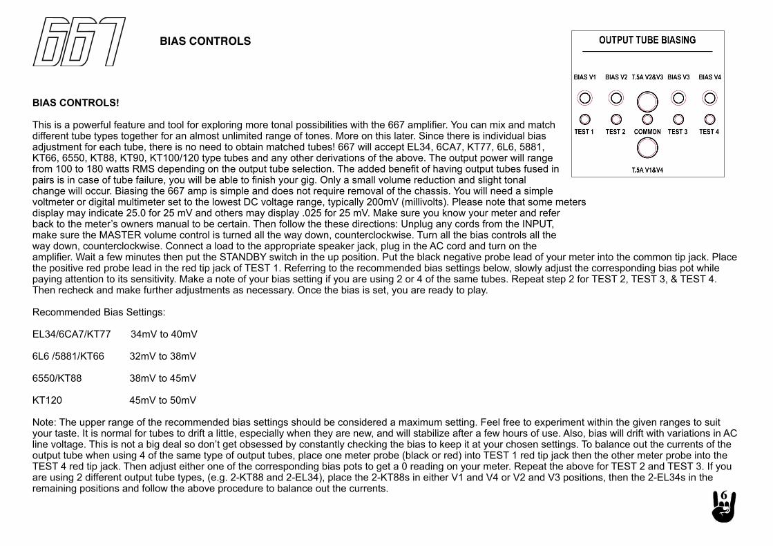
BIAS CONTROLS!
This is a powerful feature and tool for exploring more tonal possibilities with the 667 amplifier. You can mix and match different tube types together for an almost unlimited range of tones. More on this later. Since there is individual bias adjustment for each tube, there is no need to obtain matched tubes! 667 will accept EL34, 6CA7, KT77, 6L6, 5881,KT66, 6550, KT88, KT90, KT100/120 type tubes and any other derivations of the above. The output power will range from 100 to 180 watts RMS depending on the output tube selection. The added benefit of having output tubes fused in pairs is in case of tube failure, you will be able to finish your gig. Only a small volume reduction and slight tonal change will occur. Biasing the 667 amp is simple and does not require removal of the chassis. You will need a simple voltmeter or digital multimeter set to the lowest DC voltage range, typically 200mV (millivolts). Please note that some metersdisplay may indicate 25.0 for 25 mV and others may display .025 for 25 mV. Make sure you know your meter and referback to the meter’s owners manual to be certain. Then follow the these directions: Unplug any cords from the INPUT,make sure the MASTER volume control is turned all the way down, counterclockwise. Turn all the bias controls all theway down, counterclockwise. Connect a load to the appropriate speaker jack, plug in the AC cord and turn on theamplifier. Wait a few minutes then put the STANDBY switch in the up position. Put the black negative probe lead of your meter into the common tip jack. Place the positive red probe lead in the red tip jack of TEST 1. Referring to the recommended bias settings below, slowly adjust the corresponding bias pot while paying attention to its sensitivity. Make a note of your bias setting if you are using 2 or 4 of the same tubes. Repeat step 2 for TEST 2, TEST 3, & TEST 4. Then recheck and make further adjustments as necessary. Once the bias is set, you are ready to play.
Recommended Bias Settings:
EL34/6CA7/KT77 34mV to 40mV
6L6 /5881/KT66 32mV to 38mV
6550/KT88 38mV to 45mV
KT120 45mV to 50mV
Note: The upper range of the recommended bias settings should be considered a maximum setting. Feel free to experiment within the given ranges to suit your taste. It is normal for tubes to drift a little, especially when they are new, and will stabilize after a few hours of use. Also, bias will drift with variations in AC line voltage. This is not a big deal so don’t get obsessed by constantly checking the bias to keep it at your chosen settings. To balance out the currents of the output tube when using 4 of the same type of output tubes, place one meter probe (black or red) into TEST 1 red tip jack then the other meter probe into the TEST 4 red tip jack. Then adjust either one of the corresponding bias pots to get a 0 reading on your meter. Repeat the above for TEST 2 and TEST 3. If you are using 2 different output tube types, (e.g. 2-KT88 and 2-EL34), place the 2-KT88s in either V1 and V4 or V2 and V3 positions, then the 2-EL34s in the remaining positions and follow the above procedure to balance out the currents.
!

!
!
!
TUBE LAYOUT!
Preamp tubes left to right (with control panel facing you):!
V1 12ax7 CH5/6 input!
V2 12ax7 CH5/6 2nd&3rd stages!
V3 12ax7 CH5/6 4th&CF stages!
V4 12ax7 CH3/4 and CH1/2 input!
V5 12ax7 CH3/4 2nd&3rd stages!
V6 12ax7 CH3/4 4th&CF stages!
V7 12ax7 CH1/2 2nd&3rd stages!
V8 12ax7 LOOP!
V9 12ax7 PI!
V10-V13 Power Output Tubes!
1x4 OHM - connect one 4 ohm speaker cabinets here!
2x8 OHM - connect two 8 ohm speaker cabinets here!
1x8 OHM - connect one 8 ohm speaker cabinets here!
2x16 OHM - connect two 16 ohm speaker cabinets here!
1x16 OHM - connect one 16 ohm speaker cabinets here!
DO NOT CONNECT MORE SPEAKERS THAN SHOWN ABOVE!
LINEOUT OUTPUT is tapped directly off the speaker jack and the LEVEL sets the signal output. !
LOUDSPEAKERS & LINE OUTPUTS!
667 is preset to MIDI Channel 1. The 2 outside pins of the MIDI IN 7 pin!
connector feeds 9VAC at 1.5amps to power midi foot controls. If your midi!
foot controller has self power via the 2 outside pins on a 5 pin cable, the!
667 will also supply power to it.!
Midi CC numbers as follows:!
80 CH1!
81 CH2!
82 CH3!
83 CH4!
84 CH5!
85 CH6!
86 Boost 1 through 6!
87 Loop On!
88 Voicing L!
89 Voicing M!
90 Voicing H!
91 Loop 2!
92 Master 2!
MIDI CONTROLS!
MAINS SWITCH: Selects the country voltage. For 100-120VAC selections, change IEC fuse to T5A/250V fuse. For 220-240VAC selections, change IEC fuse to T2.5A/250V fuse. The H.T. Fuse remains unchanged.!
MAINS INPUT: AC wall power via included IEC cord to a grounded outlet HT FUSE: Protection for AC power faults.!
For detailed product videos please visit our website at :www.randallamplification.com Randall Amplifiers is a Division of U.S. Music Corp.!1000 Corporate Grove Drive • Buffalo Grove, IL 60089!Tel: (800) 877-6863 • Fax: (847) 949-8444
Randall Warranty Randall Amplifiers, a Division of U.S. Music Corporation warrants the product you have purchased to be free of defects in materials and workmanship in normal use for a period of two (2) years from the date of original purchase. This warranty shall run to the original purchaser when purchased from an Authorized Randall Dealer. The manufacturer warrants speakers for a period of (1) years. The manufacturer warrants tubes for a period of (90) days. Defective parts found during the applicable warranty period with proof of purchase will be replaced or repaired without charge if the complete product is returned to US Music Corp or any Authorized Randall Service Center within the U.S.A. Randall reserves the right to use materials readily available at the time of the repair. All Warranty service requires Proof of Purchase (sales receipt) to be presented at time of service request. Any repair or service performed by any person of entity other than an Authorized Service Center is not covered by this limited warranty. The customer pays transportation to and from Randall factory service or any Randall Authorized Service Center. Rental stock is warranted for (1) year from date of invoice to the Authorized dealer. Warranty on rental units is not transferable.
What is covered against manufacturing defects: Parts and Labor to correct any defect in materials used and any defect attributable to workmanship.
What is not covered:
Shipping Damage. Report damage upon receipt of item to the carrier (i.e. UPS). Freight carrier must be notified upon receipt of items to insure freight damage claim resolution. Shipping damage not filed with carriers within (48) hrs upon receipt will not be covered under warranty. Report any shipping damage within (48) hrs of receipt to the Randall Customer Service Dept at 1-847-949-0444, ext. 5120. Keep all original documents and packing materials to insure freight damage claim resolution. Merchandise that has been modified after original shipment from the Randall factory. Products whose serial numbers have been altered or removed. Exterior normal wear and tear damage to the finish due to misuse, operation outside the specified ratings, neglect or accident. Warranty claims by anyone other than the original purchaser. Randall is not responsible for any items left in protective covers or cases, (We strongly advise that all personal items such as chords, cables, tuners, etc… be removed!) freight charges to and from the factory or an Authorized service center on customer owned goods, any and all charges incurred from priority service requests (Rush Service) or priority shipping for replacement parts. Any and all charges if no problem is found.
Return AuthorizationAll items being returned for any reason must have a Return Authorization number. This RA# must be placed on the outside of the carton of the item being returned or the carton will be refused upon delivery. Please call the customer service department at 1-800-877-6863, ext. 5120, for the return authorization number. Dealer stock items will be returned to the dealer freight prepaid.
An Authorized Warranty Service Center must perform any and all field warranty service work. Customer will not pay for parts and/or labor provided the problem found is within warranty guidelines. Proof of purchase must be provided at the time of service request. Transportation charges to and from the Authorized Warranty Service Center are the responsibility of the customer. Rush service charges and special freight charges for required parts are not covered under warranty and are also the responsibility of the customer. If a unit is not easily transported to an authorized service center, the customer is responsible for technician travel charges. Any charges for labor or processing when no problem is found are also not covered under warranty. Any charges incurred for work performed by an unauthorized service center are the responsibility of the customer.
Warranty terms may very per country, check warranty terms with local Distributor or at point of purchase.