6(59,&(0$18$/ - tim.id.autim.id.au/laptops/dell/latitude lm.pdf · factory repair parts and...
TRANSCRIPT

'HOO® /DWLWXGH® /0
6(59,&(�0$18$/
®

Information in this manual is subject to change without notice.
1994–1996 Dell Computer Corporation. All rights reserved.
Printed in the United States of America. Reproduction in any manner whatsoever without the written permission of Dell Computer Corporation is strictly forbidden.
Trademarks used in this text: Dell, the DELL logo, and Latitude are registered trademarks of Dell Computer Corporation; MS-DOS is a registered trademark of Microsoft Corporation; Intel and Pentium are registered trademarks of Intel Corporation; IBM is a registered trademark of International Business Machines Corporation.
Other trademarks and trade names may be used in this document to refer to either the entities claiming the marks and names or their products. Dell Computer Corporation disclaims any proprietary interest in trademarks and trade names other than its own.
June 1996 P/N 98085
Contents
. . 1-1
. 1-2
. 1-3
. 1-3
-3
1-4
. 1-4
1-4
1-4
. 1-4
. . 1-5
. . 1-5
. . 1-6
. 1-6
. 1-7
. 1-8
. 2-1
. 2-1
. 2-3
. 2-5
. 2-5
Chapter 1System Overview. . . . . . . . . . . . . . . . . . . . . . . . . . . . . . . 1-1
System Features . . . . . . . . . . . . . . . . . . . . . . . . . . . . . . . . . . . . . . . . . . . . .
Physical Description . . . . . . . . . . . . . . . . . . . . . . . . . . . . . . . . . . . . . . . . . . .
Status Display . . . . . . . . . . . . . . . . . . . . . . . . . . . . . . . . . . . . . . . . . . . . .
Keyboard Indicators . . . . . . . . . . . . . . . . . . . . . . . . . . . . . . . . . . . . .
CD-ROM/Hard-Disk Drive Indicator . . . . . . . . . . . . . . . . . . . . . . . . . 1
Diskette-Drive Access Indicator . . . . . . . . . . . . . . . . . . . . . . . . . . . . .
PC Card Indicator . . . . . . . . . . . . . . . . . . . . . . . . . . . . . . . . . . . . . . .
AC Power Indicator . . . . . . . . . . . . . . . . . . . . . . . . . . . . . . . . . . . . . .
Battery Activity Indicator . . . . . . . . . . . . . . . . . . . . . . . . . . . . . . . . . .
Battery Status Indicator . . . . . . . . . . . . . . . . . . . . . . . . . . . . . . . . . .
Battery Charge Gauge. . . . . . . . . . . . . . . . . . . . . . . . . . . . . . . . . . . . . .
Password . . . . . . . . . . . . . . . . . . . . . . . . . . . . . . . . . . . . . . . . . . . . . . . . . . .
System Power . . . . . . . . . . . . . . . . . . . . . . . . . . . . . . . . . . . . . . . . . . . . . . .
Power Conservation . . . . . . . . . . . . . . . . . . . . . . . . . . . . . . . . . . . . . . . .
Interrupt Assignments. . . . . . . . . . . . . . . . . . . . . . . . . . . . . . . . . . . . . . . . . .
Technical Specifications . . . . . . . . . . . . . . . . . . . . . . . . . . . . . . . . . . . . . . . .
Chapter 2Initial Procedures . . . . . . . . . . . . . . . . . . . . . . . . . . . . . . 2-1
Initial User Contact . . . . . . . . . . . . . . . . . . . . . . . . . . . . . . . . . . . . . . . . . . . .
Visual Inspection . . . . . . . . . . . . . . . . . . . . . . . . . . . . . . . . . . . . . . . . . . . . .
Observing the Boot Routine . . . . . . . . . . . . . . . . . . . . . . . . . . . . . . . . . . . . .
Eliminating Resource Conflicts . . . . . . . . . . . . . . . . . . . . . . . . . . . . . . . . . .
Getting Help . . . . . . . . . . . . . . . . . . . . . . . . . . . . . . . . . . . . . . . . . . . . . . . . .
v

vi
. . 3-1
. . 3-3
. 3-6
. . 4-1
. 4-2
. . 4-3
. 4-6
. 4-7
. 4-11
4-18
4-19
4-20
4-21
4-22
4-23
4-24
4-25
4-26
4-26
4-27
4-28
4-29
4-30
4-32
. 4-34
4-35
4-36
4-37
4-38
4-39
4-40
4-41
Chapter 3Beep Codes and Error Messages . . . . . . . . . . . . . . . . . . 3-1
POST Beep Codes . . . . . . . . . . . . . . . . . . . . . . . . . . . . . . . . . . . . . . . . . . .
System Error Messages . . . . . . . . . . . . . . . . . . . . . . . . . . . . . . . . . . . . . . .
Running the Dell Diagnostics. . . . . . . . . . . . . . . . . . . . . . . . . . . . . . . . . . . .
Chapter 4Removing and Replacing Parts . . . . . . . . . . . . . . . . . . . 4-1
Recommended Tools . . . . . . . . . . . . . . . . . . . . . . . . . . . . . . . . . . . . . . . . .
Screw Identification and Tightening . . . . . . . . . . . . . . . . . . . . . . . . . . . . . .
Precautionary Measures . . . . . . . . . . . . . . . . . . . . . . . . . . . . . . . . . . . . . . .
ZIF Connectors. . . . . . . . . . . . . . . . . . . . . . . . . . . . . . . . . . . . . . . . . . . . . . .
Exploded Views of Components and Assemblies . . . . . . . . . . . . . . . . . . . .
Factory Repair Parts and Assemblies. . . . . . . . . . . . . . . . . . . . . . . . . . . . .
Deleting the Password . . . . . . . . . . . . . . . . . . . . . . . . . . . . . . . . . . . . . . . . .
Hard-Disk Drive . . . . . . . . . . . . . . . . . . . . . . . . . . . . . . . . . . . . . . . . . . . . . .
Diskette Drive. . . . . . . . . . . . . . . . . . . . . . . . . . . . . . . . . . . . . . . . . . . . . . . .
CD-ROM . . . . . . . . . . . . . . . . . . . . . . . . . . . . . . . . . . . . . . . . . . . . . . . . . . .
Memory Module. . . . . . . . . . . . . . . . . . . . . . . . . . . . . . . . . . . . . . . . . . . . . .
LCD Assembly . . . . . . . . . . . . . . . . . . . . . . . . . . . . . . . . . . . . . . . . . . . . . . .
Front Bezel . . . . . . . . . . . . . . . . . . . . . . . . . . . . . . . . . . . . . . . . . . . . . . .
LCD Panel . . . . . . . . . . . . . . . . . . . . . . . . . . . . . . . . . . . . . . . . . . . . . . .
Inverter Board. . . . . . . . . . . . . . . . . . . . . . . . . . . . . . . . . . . . . . . . . . . . .
Microphone . . . . . . . . . . . . . . . . . . . . . . . . . . . . . . . . . . . . . . . . . . . . . .
LCD Assembly Latches . . . . . . . . . . . . . . . . . . . . . . . . . . . . . . . . . . . . .
Power/Suspend Indicator . . . . . . . . . . . . . . . . . . . . . . . . . . . . . . . . . . . .
Back Bezel . . . . . . . . . . . . . . . . . . . . . . . . . . . . . . . . . . . . . . . . . . . . . . .
Keyboard . . . . . . . . . . . . . . . . . . . . . . . . . . . . . . . . . . . . . . . . . . . . . . . . . . .
Top Assembly. . . . . . . . . . . . . . . . . . . . . . . . . . . . . . . . . . . . . . . . . . . . . . . .
Speakers . . . . . . . . . . . . . . . . . . . . . . . . . . . . . . . . . . . . . . . . . . . . . . . .
Status Display Board . . . . . . . . . . . . . . . . . . . . . . . . . . . . . . . . . . . . . . .
I/R Device. . . . . . . . . . . . . . . . . . . . . . . . . . . . . . . . . . . . . . . . . . . . . . . .
Power Button . . . . . . . . . . . . . . . . . . . . . . . . . . . . . . . . . . . . . . . . . . . . .
Touch Pad. . . . . . . . . . . . . . . . . . . . . . . . . . . . . . . . . . . . . . . . . . . . . . . .
Bottom Assembly . . . . . . . . . . . . . . . . . . . . . . . . . . . . . . . . . . . . . . . . . . . . .
Processor Board . . . . . . . . . . . . . . . . . . . . . . . . . . . . . . . . . . . . . . . . . . .
Power Supply Board. . . . . . . . . . . . . . . . . . . . . . . . . . . . . . . . . . . . . . . .

4-42
4-43
. 4-45
. 1-2
. 1-2
. 1-3
. 4-1
. 4-2
. 4-3
4-4
. 4-4
4-5
. 4-5
. 4-6
4-7
4-8
4-9
-10
4-18
-19
4-20
-21
-22
4-23
4-24
4-25
4-26
4-27
4-28
4-29
4-30
4-32
. 4-34
4-35
Audio Board . . . . . . . . . . . . . . . . . . . . . . . . . . . . . . . . . . . . . . . . . . . . . .
Main Board . . . . . . . . . . . . . . . . . . . . . . . . . . . . . . . . . . . . . . . . . . . . . . .
Cache Board . . . . . . . . . . . . . . . . . . . . . . . . . . . . . . . . . . . . . . . . . . . . .
Index
Figures
Figure 1-1. Front View of the Portable Computer . . . . . . . . . . . . . . . . . .
Figure 1-2. Back View of the Portable Computer . . . . . . . . . . . . . . . . . .
Figure 1-3. Status Display Panel. . . . . . . . . . . . . . . . . . . . . . . . . . . . . . . .
Figure 4-1. Computer Orientation . . . . . . . . . . . . . . . . . . . . . . . . . . . . . .
Figure 4-2. Screw Identification . . . . . . . . . . . . . . . . . . . . . . . . . . . . . . . .
Figure 4-3. Main Battery Removal . . . . . . . . . . . . . . . . . . . . . . . . . . . . . .
Figure 4-4. Hard-Disk Drive Removal . . . . . . . . . . . . . . . . . . . . . . . . . . . .
Figure 4-5. Options Bay Lock and Latch . . . . . . . . . . . . . . . . . . . . . . . . .
Figure 4-6. Diskette Drive, Secondary Battery, or CD-ROM Removal. . .
Figure 4-7. PC Card Removal. . . . . . . . . . . . . . . . . . . . . . . . . . . . . . . . . .
Figure 4-8. Releasing a ZIF Connector . . . . . . . . . . . . . . . . . . . . . . . . . .
Figure 4-9. Exploded View—Computer. . . . . . . . . . . . . . . . . . . . . . . . . . .
Figure 4-10. Exploded View—LCD Assembly . . . . . . . . . . . . . . . . . . . . . .
Figure 4-11. Exploded View—Top Assembly . . . . . . . . . . . . . . . . . . . . . . .
Figure 4-12. Exploded View—Bottom Assembly . . . . . . . . . . . . . . . . . . . 4
Figure 4-13. Capacitor C146 (Location). . . . . . . . . . . . . . . . . . . . . . . . . . .
Figure 4-14. Hard-Disk Drive Disassembly . . . . . . . . . . . . . . . . . . . . . . . . 4
Figure 4-15. Diskette Drive Assembly . . . . . . . . . . . . . . . . . . . . . . . . . . . .
Figure 4-16. CD-ROM Assembly. . . . . . . . . . . . . . . . . . . . . . . . . . . . . . . . 4
Figure 4-17. Memory Module Removal . . . . . . . . . . . . . . . . . . . . . . . . . . . 4
Figure 4-18. LCD Assembly Removal . . . . . . . . . . . . . . . . . . . . . . . . . . . .
Figure 4-19. Front Bezel Removal . . . . . . . . . . . . . . . . . . . . . . . . . . . . . . .
Figure 4-20. LCD Panel Removal . . . . . . . . . . . . . . . . . . . . . . . . . . . . . . .
Figure 4-21. Inverter Board Removal. . . . . . . . . . . . . . . . . . . . . . . . . . . . .
Figure 4-22. LCD Assembly Latches Removal . . . . . . . . . . . . . . . . . . . . .
Figure 4-23. Power/Suspend Indicator Removal . . . . . . . . . . . . . . . . . . . .
Figure 4-24. Back Bezel Removal . . . . . . . . . . . . . . . . . . . . . . . . . . . . . . .
Figure 4-25. Keyboard Removal . . . . . . . . . . . . . . . . . . . . . . . . . . . . . . . .
Figure 4-26. Top Assembly Removal. . . . . . . . . . . . . . . . . . . . . . . . . . . . .
Figure 4-27. Speakers Removal . . . . . . . . . . . . . . . . . . . . . . . . . . . . . . . .
Figure 4-28. Status Display Board Removal . . . . . . . . . . . . . . . . . . . . . . .
vii
viii
4-36
4-37
4-38
4-39
4-40
4-41
4-42
4-43
4-45
. 1-7
. 1-8
. 3-2
. 3-3
4-11
4-17
Figure 4-29. I/R Device Removal . . . . . . . . . . . . . . . . . . . . . . . . . . . . . . .
Figure 4-30. Power Button Removal . . . . . . . . . . . . . . . . . . . . . . . . . . . . .
Figure 4-31. Touch Pad Removal . . . . . . . . . . . . . . . . . . . . . . . . . . . . . . .
Figure 4-32. Bottom Assembly . . . . . . . . . . . . . . . . . . . . . . . . . . . . . . . . .
Figure 4-33. Processor Board Removal . . . . . . . . . . . . . . . . . . . . . . . . . . .
Figure 4-34. Power Supply Board Removal . . . . . . . . . . . . . . . . . . . . . . .
Figure 4-35. Audio Board Removal . . . . . . . . . . . . . . . . . . . . . . . . . . . . . .
Figure 4-36. Main Board Removal . . . . . . . . . . . . . . . . . . . . . . . . . . . . . .
Figure 4-37. Cache Board Removal . . . . . . . . . . . . . . . . . . . . . . . . . . . . . .
Tables
Table 1-1. Interrupt Assignments . . . . . . . . . . . . . . . . . . . . . . . . . . . . . .
Table 1-2. Technical Specifications . . . . . . . . . . . . . . . . . . . . . . . . . . . .
Table 3-1. POST Beep Codes . . . . . . . . . . . . . . . . . . . . . . . . . . . . . . . . .
Table 3-2. System Error Messages . . . . . . . . . . . . . . . . . . . . . . . . . . . . .
Table 4-1. Factory Repair Parts and Assemblies . . . . . . . . . . . . . . . . . .
Table 4-2. Naming Conventions . . . . . . . . . . . . . . . . . . . . . . . . . . . . . . .

ix

Read This First
Warnings, Cautions, and NotesThroughout this manual, there may be blocks of text printed in bold type or in italic type. These blocks are warnings, cautions, and notes, and they are used as follows:
NOTE: A NOTE provides helpful information about using the computer system.
A prerequisite for using this manual to service Dell portable computers is abasic knowledge of IBM-compatible PCs and prior training in IBM-compatiblePC troubleshooting techniques. In addition to information provided in thismanual, Dell provides the Reference and Troubleshooting Guide for trouble-shooting procedures and instructions on using the Dell diagnostics to testportable computers, and the online System User’s Guide for information aboutsystem setup and operations.
WARNING: A WARNING indicates the potential for bodily harm and pro-vides instructions for how to avoid the problem.
CAUTION: A CAUTION indicates either potential damage to hardware orloss of data and provides instructions for how to avoid the problem.
x

xi

xii

Chapter 1System Overview
hese
i-ed in
he
I
or is d
The Dell® Latitude® LM P-100SD and LM P-133ST are high-performancemultimedia portable computers that use the Intel® Pentium® microprocessor. This chapter provides an overview of the components and subsystems of tcomputers.
The individual model names within the Dell Latitude LM portable family indcate the type and operating frequency of the microprocessor and display usthe computer. For example:
• The Dell Latitude LM P-100SD contains a 100-MHz Pentium micro-processor and an SVGA (S) dual-scan (D) STN LCD.
• The Dell Latitude LM P-133ST contains a 133-MHz Pentium micro-processor and an SVGA (S) active-matrix (T) TFT LCD.
System FeaturesIn addition to the standard features found in IBM®-compatible portable com-puters, the Dell Latitude LM includes the following new and/or advanced features:
• 8 MB of nonremovable main memory on the main board. The memory capacity can be increased up to 40 MB by installing a matched pair of 4-, 8-, or 16-MB memory modules in the memory upgrade sockets on tmain board.
• An 11.3-inch dual-scan SVGA color display or a 12.1-inch active-matrixSVGA display.
• 42-WH lithium ion battery (nine cells).
• 256-KB SRAM level-2 external cache and 16-KB internal cache.
• NeoMagic 2070 video controller supporting all video features with a PClocal bus.
• Intel 430MX PCIset for system and PCI controller.
• Built-in microphone and jacks for connecting external speakers, micro-phones, and headphones.
• Two new diagnostics tests (infrared and audio).
• An options bay that lets users replace the secondary lithium ion batterydiskette drive without turning off or rebooting the computer. This featuresometimes called hot swapping. The CD-ROM can be inserted or removedwhile the computer is in suspend mode. This feature is sometimes calle
System Overview 1-1

1-2 Dell Latitude LM Syste
or
tor
parallel por
serial port co
infrared
mon
warm swapping. However, the CD-ROM must be in the computer before during boot in order for the drivers to load.
• Built-in serial infrared transmitter/receiver, effective to 1 m (3.3 ft).
• Support for connecting an external diskette drive to the parallel connecon the I/O panel.
Physical Description
Figure 1-1. Front View of the Portable Computer
Figure 1-2. Back View of the Portable Computer
LCD assembly
keyboard
options bay
touch pad
latch (2)
power button
hard-disk drive bay
main-battery compartment
microphone
status display panel
power/suspend indicator
touch pad button (2)
display close button
PS/2 connectorPC Card slots
t connector
nnector
I/O panel
service tag number AC adapter connector
expansion connector
port
itor connector
external microphone connector
headphones/speakers connector
ms Service Manual
l , er
m-
Status Display.
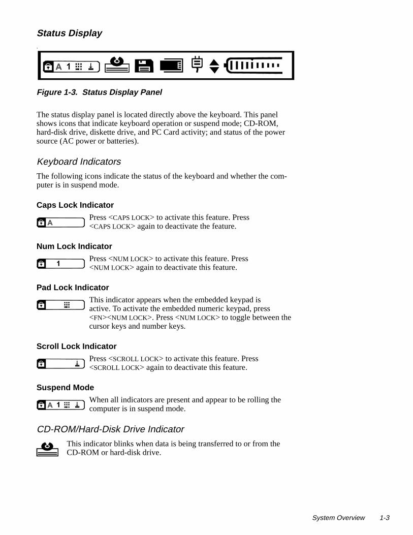
Figure 1-3. Status Display Panel
The status display panel is located directly above the keyboard. This paneshows icons that indicate keyboard operation or suspend mode; CD-ROMhard-disk drive, diskette drive, and PC Card activity; and status of the powsource (AC power or batteries).
Keyboard Indicators
The following icons indicate the status of the keyboard and whether the coputer is in suspend mode.
Caps Lock Indicator
Press <CAPS LOCK> to activate this feature. Press<CAPS LOCK> again to deactivate the feature.
Num Lock Indicator
Press <NUM LOCK> to activate this feature. Press <NUM LOCK> again to deactivate this feature.
Pad Lock Indicator
This indicator appears when the embedded keypad is active. To activate the embedded numeric keypad, press <FN><NUM LOCK>. Press <NUM LOCK> to toggle between the cursor keys and number keys.
Scroll Lock Indicator
Press <SCROLL LOCK> to activate this feature. Press <SCROLL LOCK> again to deactivate this feature.
Suspend Mode
When all indicators are present and appear to be rolling thecomputer is in suspend mode.
CD-ROM/Hard-Disk Drive Indicator
This indicator blinks when data is being transferred to or from the CD-ROM or hard-disk drive.
System Overview 1-3
1-4 Dell Latitude LM Syste
ugh
he
f the ry
link-
ery in
r or,
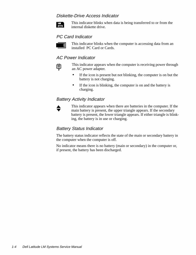
Diskette-Drive Access Indicator
This indicator blinks when data is being transferred to or from theinternal diskette drive.
PC Card Indicator
This indicator blinks when the computer is accessing data from aninstalled PC Card or Cards.
AC Power Indicator
This indicator appears when the computer is receiving power throan AC power adapter.
• If the icon is present but not blinking, the computer is on but tbattery is not charging.
• If the icon is blinking, the computer is on and the battery is charging.
Battery Activity Indicator
This indicator appears when there are batteries in the computer. Imain battery is present, the upper triangle appears. If the secondabattery is present, the lower triangle appears. If either triangle is bing, the battery is in use or charging.
Battery Status Indicator
The battery status indicator reflects the state of the main or secondary battthe computer when the computer is off.
No indicator means there is no battery (main or secondary) in the computeif present, the battery has been discharged.
ms Service Manual

nd-
r ing
-
is e.
-
is -
nd tery
Battery Charge Gauge There is a battery charge gauge on the main and secoary battery. When you press the battery test button (labeled “PUSH”), the appropriate indicator lights up foa few seconds to indicate the amount of charge remainin the battery.
Password
CAUTION: Dell strongly recommends that the user back up the pass-word onto a diskette. If the user forgets the password and does not haveit on diskette, the computer cannot be accessed. In that case, the computer must be returned to Dell at the user’s expense. Dell technicians willerase the password by shorting C146, recharge the CMOS battery, andsend the computer back at the user’s expense. For the procedure to erasethe password, see “Deleting the Password” in Chapter 4.
• The AC power indicator with the battery status in-dicator means the battery is defective.
• An indicator with one bar on the left means a batterytoo hot. Allow the battery to cool to room temperatur
• The AC power indicator with the battery status in-dicator and one bar means that the battery is too hot (40° C [104° F] or more) to start charging. Charging starts automatically when the battery cools to below 40° C.
• An indicator with no bars means that battery powerlow (about 80 percent depleted). This is the first lowbattery indication and the computer warns the userwith three short, audible beeps. There are about 20 minutes of battery life remaining.
• A blinking indicator with no bars means that batterypower is critically low (about 95 percent depleted) aneeds recharging. There are about 5 minutes of batlife remaining.
• An indicator with bars on the right side of the icon indicates the percentage of battery life remaining. Each bar equals 10 percent of battery life.
System Overview 1-5

1-6 Dell Latitude LM Syste
er wo uter. ea-hat
rve le the
hen more s
move
-ator in s any
dis-
ives a r the
o
he dis-
ati-es the
System PowerThe power button controls power to the system. The computer receives powfrom either the AC adapter connected to an AC power source or from up to tbatteries. If you use the AC adapter, constant power is available to the compIf you use one or two batteries, the system has built-in power management ftures that extend battery life by removing power from parts of the computer tare not being used.
Power Conservation
Attach the AC power adapter to the computer, whenever possible, to consebattery power. When the AC adapter is attached, the battery is charged whicomputer uses AC power.
The Power Menu of the Setup program has power conservation features. Wactivated, each power conservation feature turns off or slows down one or functions while the computer is idle. The power conservation features are afollows:
• Standby mode — To activate this feature, select the STANDBY TIME-OUT option in the Power Menu of the Setup program. To deactivate the feature, the cursor or press any key on the built-in or external keyboard.
• Suspend mode — To activate this feature, press <FN><ESC> or set the SUSPEND TIME-OUT option in the Power Menu of the Setup program. When suspend mode is activated, the computer beeps once and the suspend mode indicthe status display panel blinks every 4 seconds. To deactivate this feature, preskey on the built-in keyboard.
NOTE: To conserve power when the computer is not in use, close the play. If the display is closed and an external monitor is not connected, the computer beeps one time and goes into suspend mode. If the computer recemodem call from an external modem while the display is closed, the computeanswers the call unless it is in suspend-to-disk mode. To resume work, open display.
• Suspend-to-disk mode — To activate this feature, press <FN><A> or set the SUSPEND TO DISK TIME-OUT option in the Power Menu of the Setup program. Tresume using the computer, press the power button on the built-in keyboard.
• Dimming the display — To activate this feature, set the DIM MODE TIME-OUT option in the Power Menu of the Setup program. To increase the brightness of tplay, press any key on the built-in keyboard.
• Turning off the hard-disk drive — To activate this feature, set the HARD-DISK TIME-OUT option in the Power Menu of the Setup program. The computer automcally turns the hard-disk drive back on the next time the microprocessor accessdrive.
ms Service Manual

Interrupt Assi gnments
Table 1-1. Interrupt Assignments
IRQ Line Used/Available
IRQ0 Generated by the system timer
IRQ1 Generated by the keyboard controller to signal that the key-board output buffer is full
IRQ2 Cascade to second interrupt controller
IRQ3 Used by the infrared port (COM2)
IRQ4 Used by the serial port (COM1)
IRQ5 Used by the audio controller
IRQ6 Generated by the diskette drive controller to indicate that the diskette drive requires the attention of the microprocessor
IRQ7 Used by the parallel port
IRQ8 Generated by the system RTC
IRQ9 Software redirect to INTOA
IRQ10 Reserved
IRQ11 Reserved
IRQ12 Generated by the keyboard controller to indicate that the out-put buffer of the integrated touch pad or external PS/2 mouse is full
IRQ13 Used by the math coprocessor on the microprocessor
IRQ14 Generated by the hard-disk drive to indicate that the drive requires the attention of the microprocessor
IRQ15 Reserved
System Overview 1-7

1-8 Dell Latitude LM Syste
ype
hed
Technical Specifications
Table 1-2. Technical Specifications
Microprocessor
Microprocessor type. . . . . . . . Intel Pentium microprocessor
Microprocessor speed. . . . . . . 100 or 133 MHz
Internal cache memory . . . . . . 16 KB
External cache . . . . . . . . . . . . 256 KB
Math coprocessor . . . . . . . . . . internal to the microprocessor
Chip Set and Bus
System chip set. . . . . . . . . . . . Intel 430MX PCIset
Data bus width . . . . . . . . . . . . 64 bits
DRAM bus width . . . . . . . . . . 64 bits
Address bus width . . . . . . . . . 32 bits
Flash EPROM. . . . . . . . . . . . . 2 Mbits
PC Card
PC Card connectors . . . . . . . . two (for two type I or type II cards or one tIII card)
Cards supported . . . . . . . . . . . 3.3- and 5-V
PC Card connector size . . . . . 68 pins
Data width (maximum) . . . . . 32 bits
Memory
Architecture . . . . . . . . . . . . . . fast-page mode, two-way interleaved
Memory module capacities . . 4, 8, and 16 MB; must be installed in matcpairs
Standard RAM . . . . . . . . . . . . 8 MB on system board
Maximum RAM . . . . . . . . . . . 40 MB
ms Service Manual

bina-
Memory (Continued)
Memory access time:
tRAC . . . . . . . . . . . . . . . . 70 ns
tCAC . . . . . . . . . . . . . . . . 20 ns
BIOS address . . . . . . . . . . . . . F000:0000
Connectors
Serial (DTE) . . . . . . . . . . . . . . one 9-pin connector; 16,550-compatible, 16-byte buffer
Parallel . . . . . . . . . . . . . . . . . . one 25-hole connector; unidirectional, bidirectional, EPP 1.9, or ECP
Monitor . . . . . . . . . . . . . . . . . . one 15-hole connector
PS/2 keyboard/mouse . . . . . . . one 6-pin mini-DIN
Infrared . . . . . . . . . . . . . . . . . . one IrDA 1.0-compliant window
Audio . . . . . . . . . . . . . . . . . . . microphone; headphones/speaker
Audio
Audio type. . . . . . . . . . . . . . . . SoundBlasterPro-compatible voice and music functions
Audio controller . . . . . . . . . . . ESS 1688
Conversion . . . . . . . . . . . . . . . 16 bit (stereo analog-to-digital and digital-to-analog)
FM music synthesizer . . . . . . . 20-voice, 72-operator
Interfaces:
Internal . . . . . . . . . . . . . . . ISA bus
External . . . . . . . . . . . . . . . microphone (minijack);headphones/speaker (minijack)
Internal speaker amplifier . . . . 0.5 W stereo
Controls. . . . . . . . . . . . . . . . . . volume can be controlled through key comtions and software application menus
Table 1-2. Technical Specifications (Continued)
System Overview 1-9

1-10 Dell Latitude LM Syste
Video
Video type. . . . . . . . . . . . . . . . 64-bit (128-bit hardware accelerated) PCI
Video controller . . . . . . . . . . . NeoMagic 2070
Video memory . . . . . . . . . . . . 896 KB
Active-Matrix Display
Type . . . . . . . . . . . . . . . . . . . . active-matrix color (TFT)
Dimensions:
Height . . . . . . . . . . . . . . . 184.5 mm (7.3 inches)
Width . . . . . . . . . . . . . . . . 246.0 mm (9.7 inches)
Diagonal . . . . . . . . . . . . . . 307.5 mm (12.1 inches)
Maximum resolution . . . . . . . 800 x 600 pixels; 256 colors
Refresh rate (typical) . . . . . . . 70 Hz
Response time (typical) . . . . . 60 ms
Operating angle . . . . . . . . . . . 0° (closed) to 135°
Dot pitch . . . . . . . . . . . . . . . . . 0.31 mm
Power consumption . . . . . . . . 2.35 W
Controls . . . . . . . . . . . . . . . . . brightness can be controlled through key combinations
Dual-Scan Display
Type . . . . . . . . . . . . . . . . . . . . dual-scan color (STN)
Dimensions:
Height . . . . . . . . . . . . . . . 172.8 mm (6.8 inches)
Width . . . . . . . . . . . . . . . . 230.4 mm (9.1 inches)
Diagonal . . . . . . . . . . . . . . 287.0 mm (11.3 inches)
Maximum resolution . . . . . . . 800 x 600 pixels; 256 colors
Refresh rate (typical) . . . . . . . 70 Hz
Response time (typical) . . . . . 300 ms
Operating angle . . . . . . . . . . . 0° (closed) to 135°
Table 1-2. Technical Specifications (Continued)
ms Service Manual

apan)
t
Dual-Scan Display (Continued)
Dot pitch . . . . . . . . . . . . . . . . . 0.29 mm
Power consumption. . . . . . . . . 3.4 W
Controls. . . . . . . . . . . . . . . . . . brightness and contrast can be controlledthrough key combinations
Keyboard
Number of keys. . . . . . . . . . . . 87 (U.S. and Canada); 88 (Europe); 89 (J
Key travel . . . . . . . . . . . . . . . . 3.0 ± 0.5 mm (0.12 ± 0.02 inch)
Key spacing. . . . . . . . . . . . . . . 19.1 mm (0.75 inch)
Layout . . . . . . . . . . . . . . . . . . . QWERTY/AZERTY/Kanji
Touch Pad
Interface . . . . . . . . . . . . . . . . . PS/2-compatible
X/Y position resolutions . . . . . 20 points/mm (500 points/inch)
Size:
Thickness . . . . . . . . . . . . . 4.65 mm (0.18 inch) at highest componen
Width . . . . . . . . . . . . . . . . 62.1-mm (2.4-inch) sensor-active area
Height . . . . . . . . . . . . . . . . 49.0-mm (1.9-inch) rectangle with 0.5-mm (0.02-inch) tabs
Weight . . . . . . . . . . . . . . . . 15 g (0.52 ounce) ± 0.5 g (0.001 ounce)
Power:
Supply voltage . . . . . . . . . 5 V ± 10%
Supply current. . . . . . . . . . 4 mA (maximum operating current)
Table 1-2. Technical Specifications (Continued)
System Overview 1-11

1-12 Dell Latitude LM Syste
ing to
Main Battery
Type . . . . . . . . . . . . . . . . . . . . lithium ion
Dimensions:
Height . . . . . . . . . . . . . . . . 22.0 mm (0.86 inch)
Depth . . . . . . . . . . . . . . . . 219.0 mm (8.62 inches)
Width . . . . . . . . . . . . . . . . 57.8 mm (2.27 inches)
Weight. . . . . . . . . . . . . . . . . . . 0.44 kg (0.97 lb)
Voltage . . . . . . . . . . . . . . . . . . 10.8 VDC
Capacity . . . . . . . . . . . . . . . . . 42 WH
Charge time (approximate):1
Computer on . . . . . . . . . . . 4 hours
Computer off . . . . . . . . . . 3 hours
Operating time (approximate, with no power management features enabled):1 . . . . . . . . . 3 to 5 hours with one battery;
6 to 10 hours with two batteries
Life span (approximate)1 . . . . 500 discharge/charge cycles
Temperature range:
Charge . . . . . . . . . . . . . . . 0° to 40°C (32° to 104°F)
Discharge . . . . . . . . . . . . . 0° to 60°C (32° to 140°F)
Storage . . . . . . . . . . . . . . . -20° to 50°C (-4° to 122°F)1 Battery performance features such as charge time, operating time, and life span can vary accord
the conditions under which the computer and battery are used.
Table 1-2. Technical Specifications (Continued)
ms Service Manual

AC Adapter
Input voltage . . . . . . . . . . . . . . 90 to 264 VAC
Input current (maximum) . . . . 1.0 A at 100 VAC, full load
Input frequency . . . . . . . . . . . . 47 to 63 Hz
Output current . . . . . . . . . . . . . 2.6 A (continuous)
Output power . . . . . . . . . . . . . 34 W
Rated output voltage . . . . . . . . 16.2 VDC
Physical:
Height . . . . . . . . . . . . . . . . 27.0 mm (1.06 inches)
Width. . . . . . . . . . . . . . . . . 60.0 mm (2.36 inches)
Depth. . . . . . . . . . . . . . . . . 107.5 mm (4.23 inches)
Weight (with cables) . . . . 0.3 kg (0.66 lb)
Temperature range:
Operating . . . . . . . . . . . . . 5° to 35°C (41° to 95°F)
Storage . . . . . . . . . . . . . . . -20° to 50°C (-4° to 122°F)
Physical (Computer)
Height . . . . . . . . . . . . . . . . . . . 49.5 mm (1.95 inches)
Width. . . . . . . . . . . . . . . . . . . . 299.9 mm (11.8 inches)
Depth. . . . . . . . . . . . . . . . . . . . 228.7 mm (8.93 inches)
Weight (with hard-disk drive, diskette drive, battery, and two PC Card blanks):
Dell Latitude LM P100SD . . . . . . . . . . . 3.1 kg (6.9 lb)
Dell Latitude LM P133ST. . . . . . . . . . . . 3.1 kg (6.9 lb)
Table 1-2. Technical Specifications (Continued)
System Overview 1-13

1-14 Dell Latitude LM Syste
rum
rum
Environmental (Computer)
Temperature:
Operating . . . . . . . . . . . . . 5° to 35°C (41° to 95°F)
Storage . . . . . . . . . . . . . . . -20° to 50°C (-4° to 122°F)
Relative humidity . . . . . . . . . . 10% to 90% (noncondensing)
Maximum vibration:
Operating . . . . . . . . . . . . . 0.51 GRMS using a random-vibration spectthat simulates air shipment
Storage . . . . . . . . . . . . . . . 1.1 GRMS using a random-vibration spectthat simulates truck shipment
Maximum shock:2
Operating . . . . . . . . . . . . . 1.52 m/sec (4.98 ft/sec) (less than or equal to a pulse width of 2 ms)
Storage . . . . . . . . . . . . . . . 2.03 m/sec (6.66 ft/sec)(less than or equal to a pulse width of 2 ms)
Altitude:
Operating . . . . . . . . . . . . . 0 m to 2438 m (0 ft to 8,000 ft)
Storage . . . . . . . . . . . . . . . 0 m to 12,192 m (0 ft to 40,000 ft)2 Measured with the hard-disk drive in head-parked position.
Table 1-2. Technical Specifications (Continued)
ms Service Manual

Chapter 2Initial Procedures
m- or om-nted.
the oting :
re.
m-tions.
This chapter describes initial procedures that can help you diagnose a coputer problem. These procedures can often reveal the source of a problemindicate the correct starting point for troubleshooting the computer. Dell recmends that you perform these initial procedures in the order they are prese
Initial User ContactWhen you first contact a user who has a problem, ask the user to describeproblem and the conditions under which it occurs. A verbal description canoften indicate the cause of a problem or indicate the appropriate troubleshoprocedure to use. After the user describes the problem, follow these steps
1. Ask the user to back up any data on the hard-disk drive if the com-puter’s condition permits.
See the “Maintaining Your Computer” section of the online System’s User’s Guide.
2. Ask the user to try to duplicate the problem by repeating the operations he or she was performing at the time the problem occurred.
Can the user duplicate the problem?
Yes. Proceed to step 3.
No. Proceed to the next section, “Visual Inspection.”
3. Observe the user to determine whether he or she is making an error, such as typing an incorrect key combination or entering a command incorrectly.
Is the problem a result of user error?
Yes. Instruct the user in the proper procedure or direct him or her to theappropriate user documentation for a description of the correct procedu
No. Proceed to the next section, “Visual Inspection.”
Visual InspectionThe visual inspection consists of a quick inspection of the exterior of the coputer and any attached peripherals, including making any necessary correcFor information about the proper removal and installation of computer
Initial Procedures 2-1

2-2 Dell Latitude LM Syste
ov-
s-
pter
-
e.
components, as instructed in the following procedure, see Chapter 4, “Reming and Replacing Parts.”
To perform a visual inspection, follow these steps:
1. Determine the power state of the computer.
If the display is on, go to step 2.
If the display is off, press any key to verify that the computer is not in supend or standby mode. Then proceed to step 2.
2. Turn off any attached peripherals, and then turn off the computer. Then proceed to step 3.
3. Verify that the exterior of the computer is free of any obvious physical damage.
4. If the computer is operating from an AC adapter, verify the following:
a. The AC adapter’s AC power cable is connected to both the AC adaand the wall outlet. The AC adapter’s LED should be on.
b. The AC adapter’s DC power cable is properly connected to the computer’s AC adapter connector.
c. The AC adapter and cables are free of any obvious physical damag
5. If the computer is operating from battery power, remove any installed batteries, verify that they are free of any obvious physical damage, andthen reinsert the batteries into their respective compartments. Press thetest button located on each battery to see if there is a charge.
6. Remove the diskette drive (if installed), verify that it is free of any obvi-ous physical damage, and then reinsert the drive into its compartment.
7. Remove any installed PC Cards from the PC card slot, verify that they are free of any obvious physical damage, and then reinsert the card(s) into the PC card slot.
8. If there is a memory area problem and the computer has memory mod-ules, remove the memory modules from the main board, verify that they are free of any obvious physical damage, and then reinstall the modules.
9. Open the computer, and verify that it is free of any obvious physical damage.
10. Verify that the keyboard is free of any obvious physical damage and that its keys operate freely.
11. Verify that the touch pad and its associated buttons operate freely.
CAUTION: Before you proceed with the visual inspection, ensure thatthe user has saved all open files and exited all open application programsif possible.
ms Service Manual
of
cu-
on-
ppro-
ter-
phys-
boot ing,
ays uter.
12. If an external monitor is connected, verify the following:
a. The monitor’s interface cable is properly attached to the external-monitor connector on the computer’s I/O panel.
b. The monitor’s power cable is attached to a power source and is freeany obvious physical damage.
c. The monitor and its interface cable are free of any obvious physicaldamage.
d. The monitor’s controls are set according to the instructions in the domentation for the monitor.
13. If an external mouse is connected, verify the following:
a. The mouse is properly connected to the keyboard/keypad/mouse cnector on the computer’s I/O panel.
b. The mouse and its cable are free of any obvious physical damage.
c. The mouse’s ball and pushbuttons operate freely.
14. For any attached serial or parallel devices, verify the following:
a. The device’s interface cable connector is correctly attached to the apriate port connector on the computer’s I/O panel.
b. The captive screws that secure the connectors at each end of the inface cable are secure enough to ensure a firm connection.
c. The attached device and its interface cable are free of any obvious ical damage.
15. Turn on any attached peripherals and then the computer.
Does the problem recur?
Yes. Proceed to the next section, “Observing the Boot Routine.”
No. No further steps are necessary.
Observin g the Boot RoutineAfter you perform a visual inspection as described in the previous section, the computer from a diagnostics diskette and, while the boot routine is runnobserve the computer for any indications of problems.
NOTE: To prevent possible damage to the original diagnostics diskette, alwuse a backup copy of the diagnostics diskette when servicing a user’s compDell recommends that users make copies of the Dell Diagnostics Diskette. For instructions, see “Before You Start Testing” in Chapter 4 of the Dell Latitude LM Refer-ence and Troubleshooting Guide.
To observe the boot routine, follow these steps:
1. Turn off the computer and any attached peripherals.
2. Insert a diagnostics diskette into the diskette drive. Turn on all periph-erals and then the computer.
Initial Procedures 2-3

2-4 Dell Latitude LM Syste
ves. If e
ystem
puter
beep
3. Watch the indicators at the top of the keyboard. Depending on how your computer is configured, after various indicators flash momen-tarily in the status display panel, some indicators should light up and remain on.
Do these indicators light up within seconds after the boot routine starts?
Yes. Proceed to step 4.
No. Troubleshoot the power subsystem.
4. While the boot routine is running, observe the computer for any of the following:
• Diskette-drive and hard-disk drive access indicator activity
These indicators light in response to data being transferred to or from the drieither of these indicators fails to light during the boot routine, troubleshoot thdiskette drive or hard-disk drive subsystem, as appropriate.
• System error messages
These messages can indicate problems or provide status information. If a serror message is displayed, refer to Table 3-2.
• Beep codes
A beep code is a series of beeps that indicates an error condition. If the comemits a beep code, refer to Table 3-1.
NOTE: The computer beeps once shortly after the system boots. Thisis normal and not part of a beep code.
• Any unusual sounds
5. Observe the display for the Diagnostics Menu of the Dell diagnostics.
Does the Diagnostics Menu appear on the display?
Yes. See “Running the Dell Diagnostics” in Chapter 3.
No. Proceed to step 6.
6. Insert another copy of the diagnostics diskette into the diskette drive, and reboot the computer.
Does the Diagnostics Menu appear on the display?
Yes. See “Running the Dell Diagnostics” in Chapter 3.
No. Proceed to the next section, “Eliminating Resource Conflicts.”
ms Service Manual
ry an be o two
com-
reas-flicts,
r lead em, ting
Eliminatin g Resource ConflictsDevices within or connected to the computer may require dedicated memospaces, interrupt levels, and/or DMA channels. Because different devices cconfigured at different times, it is possible the same resource is assigned tor more devices.
Disconnect all peripherals and remove all PC Cards to make sure that the puter failure is not caused by faulty devices.
If you suspect that resource conflicts might exist, check the computer and sign the resources as necessary. For more information about resolving consee Chapter 3, “Troubleshooting Your Computer,” in the Reference and Trouble-shooting Guide.
Gettin g HelpIf none of the procedures in this chapter reveal the source of the problem oto the proper troubleshooting steps for determining the source of the problcontact Dell for technical assistance. For instructions, see Chapter 5, “GetHelp,” in the Reference and Troubleshooting Guide or the “Contacting Dell” section of the online System User’s Guide.
Initial Procedures 2-5

2-6 Dell Latitude LM Syste
ms Service Manual
Chapter 3Beep Codes and Error Messa ges
occur puter or sys-ase.
sages te nos-
ay y a may uires uter
This chapter describes beep codes and system error messages that can during system start-up or, in the case of some failures, during normal comoperation. The tables in this chapter list faults that can cause a beep code tem error message to occur and the probable causes of the fault in each c
If a faulty computer does not emit beep codes or display system error mesto indicate a failure, you should load the diagnostics and run the appropriatests to help isolate the source of the problem. See “Running the Dell Diagtics” found later in this chapter.
POST Beep CodesIf the display cannot display error messages during POST, the computer memit a series of beeps that identify the problem or that can help you identiffaulty component or assembly. The following table lists the beep codes thatbe generated during POST. Most beep codes indicate a fatal error that reqreplacement of the main board or other corrective actions before the compcan operate.
Beep Codes and Error Messages 3-1

3-2 Dell Latitude LM Syste
Table 3-1. POST Beep Codes
Beep Code Error Probable Causes
1-2 Memory module not being properly identified or used
Faulty memory module or faulty main board
1-2-2-3 ROM BIOS checksum failure Faulty main board
1-3-1-1 DRAM refresh failure Faulty main board
1-3-1-3 Keyboard controller test fail-ure
Faulty keyboard or faulty main board
1-3-4-1 RAM failure on address line nnnn
Faulty memory module or faulty main board
1-3-4-3 RAM failure on data bits nnnn of high byte on memory bus
Faulty memory module or faulty main board
1-4-1-1 RAM failure on data bits nnnn of low byte on memory bus
Faulty memory module or faulty main board
2-1-2-3 Check ROM copyright notice failure
Faulty main board
2-2-3-1 Interrupt mask register failure Faulty main board
ms Service Manual
may
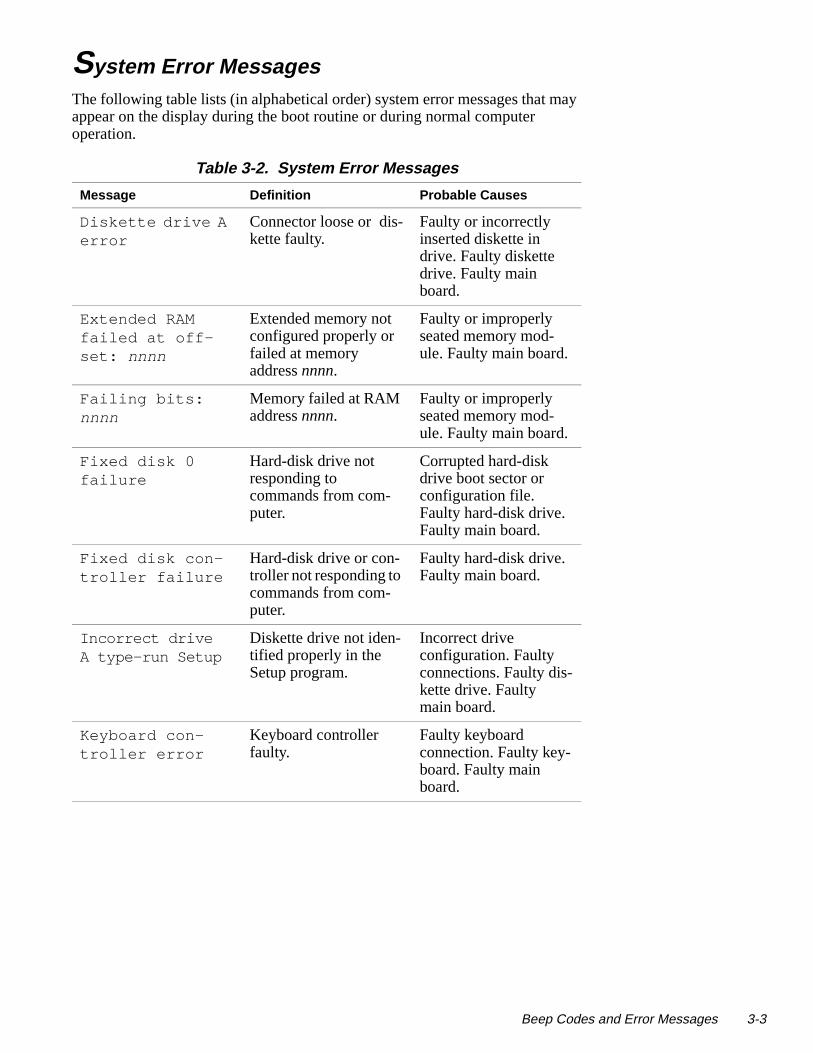
System Error Messa gesThe following table lists (in alphabetical order) system error messages thatappear on the display during the boot routine or during normal computer operation.
Table 3-2. System Error Messages
Message Definition Probable Causes
Diskette drive A error
Connector loose or dis-kette faulty.
Faulty or incorrectly inserted diskette in drive. Faulty diskette drive. Faulty main board.
Extended RAM failed at off-set: nnnn
Extended memory not configured properly or failed at memory address nnnn.
Faulty or improperly seated memory mod-ule. Faulty main board.
Failing bits: nnnn
Memory failed at RAM address nnnn.
Faulty or improperly seated memory mod-ule. Faulty main board.
Fixed disk 0 failure
Hard-disk drive not responding to commands from com-puter.
Corrupted hard-disk drive boot sector or configuration file. Faulty hard-disk drive. Faulty main board.
Fixed disk con-troller failure
Hard-disk drive or con-troller not responding to commands from com-puter.
Faulty hard-disk drive. Faulty main board.
Incorrect drive A type—run Setup
Diskette drive not iden-tified properly in the Setup program.
Incorrect drive configuration. Faulty connections. Faulty dis-kette drive. Faulty main board.
Keyboard con-troller error
Keyboard controller faulty.
Faulty keyboard connection. Faulty key-board. Faulty main board.
Beep Codes and Error Messages 3-3

3-4 Dell Latitude LM Syste
Keyboard error Keyboard not respond-ing correctly.
Built-in keyboard: Faulty keyboard or key pressed while com-puter booting. External keyboard: Cable or connector loose. Faulty keyboard or key pressed while computer booting.
Operating system not found
Operating system can-not be found on hard-disk drive or on diskette in diskette drive.
Incorrect drive configuration. Operat-ing system not installed on hard-disk drive or diskette drive not bootable. Faulty con-nections. Faulty drive. Faulty main board.
Parity check 1 nnnn
Parity error in system bus at address nnnn.
Faulty main board.
Parity check 2 nnnn
Parity error in I/O bus at address nnnn.
Faulty main board.
Real time clock error
CMOS battery that supports data stored in NVRAM may be dead.
Faulty battery. Faulty main board.
Shadow RAM failed at off-set: nnnn
Shadow RAM failed at address nnnn.
Faulty or improperly seated memory mod-ule. Faulty main board.
System battery is dead—Replace and run Setup
CMOS battery dead. Faulty CMOS battery or main board.
System cache error—cache disabled
Primary cache failed. Faulty microprocessor.
Table 3-2. System Error Messages (Continued)
Message Definition Probable Causes
ms Service Manual

System CMOS checksum bad—run Setup
CMOS has been cor-rupted or modified, pos-sibly by an application program that changes data stored in CMOS.
BIOS has been updated.
System RAM failed at off-set: nnnn
Memory not operating correctly. System RAM failed at address nnnn in the 64-KB block at which error was detected.
Faulty or improperly seated memory mod-ule. Faulty main board.
System timer error
Timer circuit on main board malfunctioning.
Faulty main board.
Table 3-2. System Error Messages (Continued)
Message Definition Probable Causes
Beep Codes and Error Messages 3-5

3-6 Dell Latitude LM Syste
r.
m
face
into
a oads,
nos-t to
r
Runnin g the Dell Dia gnostics
The Dell diagnostics contains tests that aid in troubleshooting the computeThe diagnostics diskette contains the following test groups:
• RAM — Tests the main memory
• System Set — Tests the primary functions of the main board
• Video — Tests the video subsystem
• Keyboard — Tests the keyboard subsystem
• Mouse — Tests the mouse/touch pad subsystem
• Diskette Drives — Tests the diskette drive subsystem
• Hard-Disk Drives (Non-SCSI) — Tests the IDE hard-disk drive subsyste
• IDE CD ROM Drives — Tests a CD-ROM drive subsystem
• Serial/Infrared Ports — Tests the serial communications port
• Parallel Ports — Tests the parallel communications port
• Audio — Tests the operation of the audio chip set
• SCSI Devices — Tests a SCSI hard-disk drive subsystem
NOTE: This test does not apply to Dell Latitude LM computers.
• Network Interface — Tests a network controller and its associated inter
NOTE: This test does not apply to Dell Latitude LM computers.
To start the diagnostics, turn off the computer, insert a diagnostics diskettethe diskette drive, and then turn on the computer.
Starting the diagnostics causes the Dell logo screen to appear, followed bymessage indicating that the diagnostics is loading. Before the diagnostics la program tests the portion of main memory (RAM) required for loading thediagnostics. If a main memory error is detected, a message appears on thescreen telling you a memory module has failed.
If no errors are found in main memory, the diagnostics loads, and the Diagtics Menu appears. This menu lets you choose the following options or exithe MS-DOS® prompt:
• RUN QUICK TESTS — Runs preselected tests to quickly locate a computefailure or to indicate where further testing is needed to isolate a failure
• RUN ALL TESTS — Runs all tests for a thorough test of the computer
• RUN SPECIFIC TESTS — Tests a particular area or subsystem of the computer
CAUTION: To prevent damage to the original diagnostics diskette,always use a backup copy of the diagnostics diskette when servicing a user’scomputer. Dell recommends that users make several copies of this diskette toensure that one is always available.
ms Service Manual

Chapter 4Removin g and Replacin g Parts
s,
e
pher-
e in
sem-mbly. not he dure.
s:
This chapter provides procedures for removing and replacing componentassemblies, and subassemblies.
Unless otherwise noted, each of the procedures in this chapter assumes thfollowing:
• The computer and any attached peripherals are turned off and the perials disconnected from the computer’s I/O panel.
• A part can be replaced or installed by performing the removal procedurreverse order.
When performing the procedures in this chapter that require the display asbly to be open, use a book or something similar to support the display asseThe angle of the display assembly with respect to the bottom case should exceed 135 degrees. Also, assume that locations or directions relative to tcomputer are as shown in Figure 4-1 unless otherwise specified in a proce
Figure 4-1. Computer Orientation
Recommended Tools Most of the procedures require the use of one or more of the following tool
• Small flat-blade screwdriver
• Number 1 magnetized Phillips-head screwdriver
• Antistatic grounding strap
• Needle-nose pliers
right side left side
back of computer
front of computer
Removing and Replacing Parts 4-1
4-2 Dell Latitude LM Syste
ns. ided
• Small scribe (or Delrin [plastic] screwdriver)
• Nut drivers
• Chip removal tool
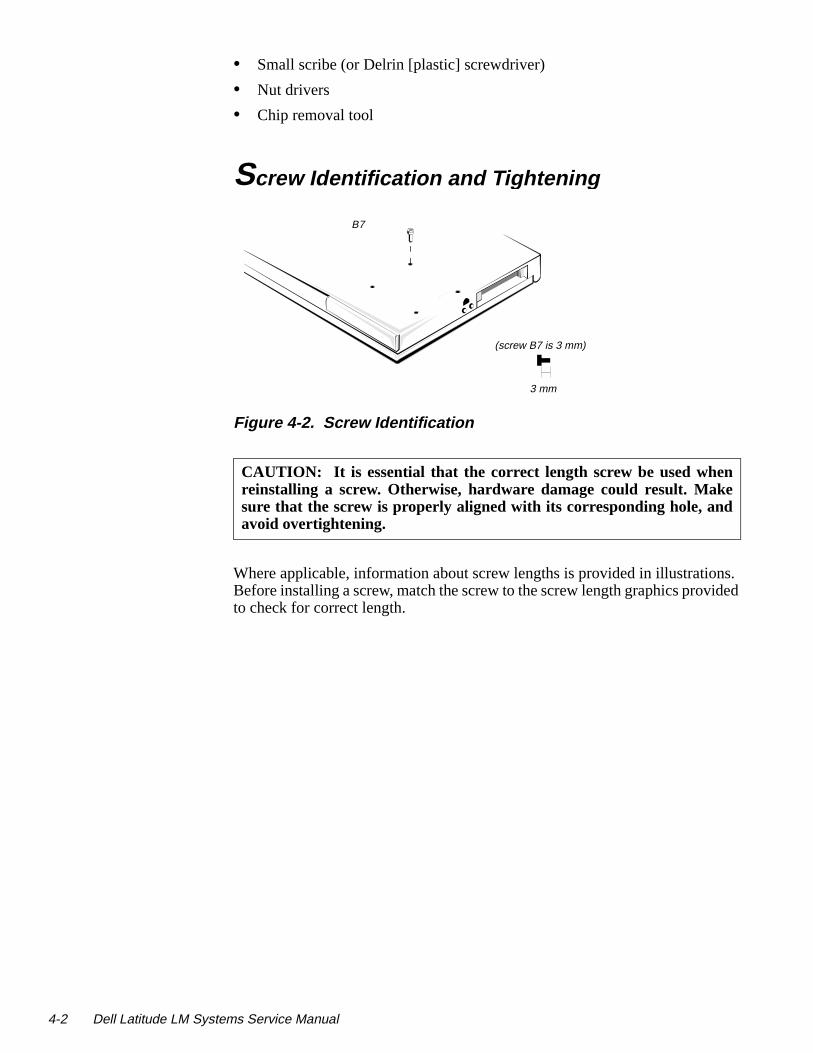
Screw Identification and Ti ghtenin g.
Figure 4-2. Screw Identification
Where applicable, information about screw lengths is provided in illustratioBefore installing a screw, match the screw to the screw length graphics provto check for correct length.
CAUTION: It is essential that the correct length screw be used whenreinstalling a screw. Otherwise, hardware damage could result. Makesure that the screw is properly aligned with its corresponding hole, andavoid overtightening.
B7
(screw B7 is 3 mm)
3 mm
ms Service Manual

-
l it
Precautionary Measures Before performing any of the procedures in this chapter, read the followingwarning.
1. Determine the power state of the computer.
If the display is on, go to step 2.
If the display is off, press any key on the keyboard to verify that the computer is not in suspend or standby mode. Then proceed to step 2.
2. Turn off the computer and any attached peripherals.
3. Disconnect the computer and any attached peripherals from AC powersources to reduce the potential for personal injury or shock.
4. Remove the main battery from the battery compartment.
On the right side of the computer, press down on the battery cover untiunlocks and pull the battery straight out.
Figure 4-3. Main Battery Removal
WARNING FOR YOUR PERSONAL SAFETY AND PROTECTIONOF THE EQUIPMENT: Before you start to work on the computer, per-form the following steps in the sequence indicated.
1. Turn off the computer and any attached peripherals.
2. Disconnect the computer and any attached peripherals from ACpower sources to reduce the potential for personal injury or shock.
3. Ground yourself by attaching an antistatic grounding strap to yourwrist and to an unpainted metal surface on the computer’s I/O panel.If an antistatic grounding strap is not available, periodically dis-charge static electricity from your body by touching one of theconnectors on the I/O panel.
cover
Removing and Replacing Parts 4-3
4-4 Dell Latitude LM Syste
m-ive ront
y or is d
or
e the ay
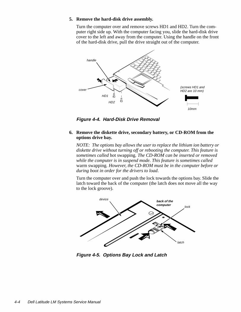
5. Remove the hard-disk drive assembly.
Turn the computer over and remove screws HD1 and HD2. Turn the coputer right side up. With the computer facing you, slide the hard-disk drcover to the left and away from the computer. Using the handle on the fof the hard-disk drive, pull the drive straight out of the computer.
Figure 4-4. Hard-Disk Drive Removal
6. Remove the diskette drive, secondary battery, or CD-ROM from the options drive bay.
NOTE: The options bay allows the user to replace the lithium ion batterdiskette drive without turning off or rebooting the computer. This featuresometimes called hot swapping. The CD-ROM can be inserted or removedwhile the computer is in suspend mode. This feature is sometimes callewarm swapping. However, the CD-ROM must be in the computer beforeduring boot in order for the drivers to load.
Turn the computer over and push the lock towards the options bay. Slidlatch toward the back of the computer (the latch does not move all the wto the lock groove).
Figure 4-5. Options Bay Lock and Latch
cover
handle
HD1
HD2
(screws HD1 and HD2 are 10 mm)
10mm
lock
latch
deviceback of the computer
ms Service Manual

ith
om
.
Keep holding the latch with one hand while pulling the device (diskette drive, secondary battery, or CD-ROM) straight out of the options bay wthe other.
Figure 4-6. Diskette Drive, Secondary Battery, or CD-ROM Removal
7. Remove any PC Cards
To remove a PC Card from the top connector, press the top eject button (identified by an arrow pointing up). To remove a PC Card from the bottconnector, press the bottom eject button (identified by an arrow pointing down). If you are removing a type III card, press the bottom eject button
Figure 4-7. PC Card Removal
Removing and Replacing Parts 4-5

4-6 Dell Latitude LM Syste
con-
on-main
y
ZIF Connectors Some of the computer’s interface connectors are zero insertion force (ZIF)nectors. These connectors are not removable; they must be released to disconnect a cable from them.
To disconnect an interface cable from a ZIF connector, follow these steps:
1. Insert a small flat-blade screwdriver under the movable part of the connector.
For most ZIFs, carefully pry up first one end of the movable part of the cnector and then the other end. Some ZIFs (keyboard connector on the board) may need to be lifted in the center.
.
Figure 4-8. Releasing a ZIF Connector
2. Pull up gently on the movable part of the connector until it releases theinterface cable.
3. Grasp the interface cable and pull it out of the connector.
To reconnect an interface cable to a ZIF connector, follow these steps:
1. Use the flat-blade screwdriver to open the movable part of the ZIF connector.
2. Orient the end of the interface cable with the ZIF connector, and insert the end of the cable into the connector.
3. While holding the cable in place, close the ZIF connector.
To ensure a firm connection, make sure the ZIF connector is completelclosed.
CAUTION: ZIF connectors are fragile. To avoid breaking the connec-tors, touch them carefully. Do not apply too much pressure to themovable part of the connector when opening or closing it.
ms Service Manual

Exploded Views of Components and Assemblies .
Figure 4-9. Exploded View—Computer
LCD panel assembly
keyboard
bottom assembly
diskette drive,secondary battery, or CD-ROM
hard-disk drive
main battery
heat sink
latch (2)
power/ suspend indicator
Removing and Replacing Parts 4-7

4-8 Dell Latitude LM Syste
Figure 4-10. Exploded View—LCD Assembly
front bezel
LCD panel
power/suspend indicator
inverter board
inverter board connectormicrophone
latch
back bezel
LCD panel flex cable
stiffener
hinge (2)
ms Service Manual

infrared lens
infrared board
panel board cable
nk
top assembly
.
Figure 4-11. Exploded View—Top Assembly
keyboard flex cable keyboard
LCD flex- cable cover
power button
keyboard screw cover (2)
hinge cover
touch pad button (2)
touch pad
touch-pad button board
plastic housing (2) status-display panel board
speaker (2)
touch pad bracket
heat si
spring
Removing and Replacing Parts 4-9

4-10 Dell Latitude LM Syste
main board
audio boar
cache board
bottom assembly
.
Figure 4-12. Exploded View—Bottom Assembly
power boardd
I/O panel door
I/O bracket
memory module cover
processor board
ms Service Manual

g fac-ence the
-
se at are
Factory Repair Parts and AssembliesThis section contains a parts list and procedures for removing and replacintory components and subassemblies. This information is provided for referonly. Dell does not recommend removal and replacement of these parts infield.
Table 4-1 lists the factory repair parts and assemblies available for the computer. Some parts may only be available as part of a kit or assembly. The subsections that follow provide instructions for removing and replacing theparts and assemblies. An asterisk (*) identifies those parts or assemblies threplaceable by a customer. .
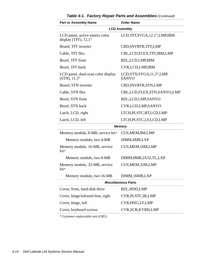
Table 4-1. Factory Repair Parts and Assemblies
Part or Assembly Name Order Name
AC Adapter/Power Cables
AC Adapter, service kit* CUS,ADPT,AC,EXT,16.2V,34W,LMP
AC Adapter* ADPT,AC,EXT,16.2V,34W,LMP
Cable, power, U.S. CORD,PWR,110V,6F,AC ADPT,US
Cable, power, Australia CORD,PWR,220V,6F,AC ADPT,AUS
Batteries
Battery, main, 42-WH* BTRY,MAIN,42WHR,LIION,LMP
Battery, secondary* BTRY,2ND,LIION,LMP
Board Assemblies
Board assembly, 100-MHz, service kit
SVC,SYS,PLN,LMP100SD
Main board SYS,PLN,3.3V STN LCD,LMP
Processor board, 100-MHz CRD,PRCR,LMP100
Card, cache CRD,L2,CACHE,LMP
Heat sink, microprocessor, subassembly
SUBASSY,HTSNK,CPU,LMP
Board, power supply CRD,CONV,DC-DC,LMP
Insulator, main board INSUL,MYLAR,PWA,LMP
* Customer-replaceable unit (CRU)
Removing and Replacing Parts 4-11

4-12 Dell Latitude LM Syste
Board Assemblies (Continued)
Board assembly, 133-MHz, service kit
SVC,SYS,PLN,LMP133ST
Main board SYS,PLN,3.3V TFT LCD,LMP
Processor board, 133-MHz CRD,PRCR,LMP133
Card, cache CRD,L2,CACHE,LMP
Heat sink, microprocessor, subassembly
SUBASSY,HTSNK,CPU,LMP
Board, power supply CRD,CONV,DC-DC,LMP
Insulator, main board INSUL,MYLAR,PWA,LMP
Boards and Cards
Board, status display panel CRD,CNTRL,SPKR,LMP
Board, infrared CRD,IR,LMP
Board, audio CRD,AUDIO,LMP
Cable, audio board CBL,FLEX,JK,AUD,LMP
CD-ROM
CD-ROM, service kit* CUS,CD ROM,4X,LMP,SANYO
CD-ROM drive CD ROM,4X,LMP,SANYO
Diskette Drive Assembly
Diskette drive assembly* CUST,FD,INT/EXT,LMP
Diskette drive, internal/external FD,INT/EXT,LMP
Case, upper PLSTC,UPR,FD,LMP
Case, lower PLSTC,LWR,FD,LMP
Cable, service kit* CUST,CBL,FD,INT/EXT,LMP
Connector, cable CBL,FD,INT/EXT,LMP
* Customer-replaceable unit (CRU)
Table 4-1. Factory Repair Parts and Assemblies (Continued)
Part or Assembly Name Order Name
ms Service Manual

Hard-Disk Drive Assemblies
Hard-disk drive, 540-MB, service kit*
CUS,HD,540MB,I,F2,12.5MM,NBK
Hard-disk drive, subassembly, 540-MB
SUBASSY,HD,540MB,LF2,12.5MM,NBK
Hard-disk drive, 540-MB HD,540MB,I,F2,12.5MM,NBK
Bracket, hard-disk drive BRKT,HD,12.5MM,LMP
Screws, bracket SCR,3X.5X3,FLH,PNH,MS,ZPS,HD
Hard-disk drive, 810-MB, service kit*
CUS,HD,810MB,12.5MM,NN,#1,NBK
Hard-disk drive, 810-MB SUBASSY,HD,810MB,12.5MM,NN,NBK
Hard-disk drive, 810-MB HD,810MB,I,F2,12.5MM,NN,#1,NBK
Bracket, hard-disk drive BRKT,HD,12.5MM,LMP
Screws, bracket SCR,3X.5X3,FLH,PNH,MS,ZPS,HD
Hard-disk drive, 1.4-GB, service kit* CUS,HD,1.4GB,12.5MM,NN,#1,NBK
Hard-disk drive, 1.4-GB SUBASSY,HD,1.4GB,12.5MM,NN,NBK
Hard-disk drive, 1.4-GB HD,1.4GB,I,F2,12.5MM,NN,#1,NBK
Bracket, hard-disk drive BRKT,HD,12.5MM,NBK
Screws, bracket SCR,3X.5X3,FLH,PNH,MS,ZPS,HD
Keyboards
Keyboard, U.S. KYBD,87,LMP,US,SMK
Keyboard, Latin/Spanish KYBD,88,LMP,LTN/SPN,SMK
Keyboard, Japan KYBD,89,LMP,JPN,SMK
* Customer-replaceable unit (CRU)
Table 4-1. Factory Repair Parts and Assemblies (Continued)
Part or Assembly Name Order Name
Removing and Replacing Parts 4-13
4-14 Dell Latitude LM Syste
LCD Assembly
LCD panel, active-matrix color display (TFT), 12.1”
LCD,TFT,SVGA,12.1”,LMP,IBM
Board, TFT inverter CRD,INVRTR,TFT,LMP
Cable, TFT flex CBL,LCD,FLEX,TFT,IBM,LMP
Bezel, TFT front BZL,LCD,LMP,IBM
Bezel, TFT back CVR,LCD,LMP,IBM
LCD panel, dual-scan color display (STN), 11.3”
LCD,STN,SVGA,11.3”,LMP,SANYO
Board, STN inverter CRD,INVRTR,STN,LMP
Cable, STN flex CBL,LCD,FLEX,STN,SANYO,LMP
Bezel, STN front BZL,LCD,LMP,SANYO
Bezel, STN back CVR,LCD,LMP,SANYO
Latch, LCD, right LTCH,PLSTC,RT,LCD,LMP
Latch, LCD, left LTCH,PLSTC,LF,LCD,LMP
Memory
Memory module, 8-MB, service kit* CUS,MEM,8M,LMP
Memory module, two 4-MB SIMM,4MB,LXP
Memory module, 16-MB, service kit*
CUS,MEM,16M,LMP
Memory module, two 8-MB DIMM,8MB,2X32,TL,LXP
Memory module, 32-MB, service kit*
CUS,MEM,32M,LMP
Memory module, two 16-MB DIMM,16MB,LXP
Miscellaneous Parts
Cover, front, hard-disk drive BZL,HDD,LMP
Cover, hinge/infrared lens, right CVR,PLSTC,IR,LMP
Cover, hinge, left CVR,HNG,LF,LMP
Cover, keyboard screws CVR,SCR,KYBD,LMP
* Customer-replaceable unit (CRU)
Table 4-1. Factory Repair Parts and Assemblies (Continued)
Part or Assembly Name Order Name
ms Service Manual

Miscellaneous Parts (Continued)
Cover, flex-cable CVR,HNG,CTR,LMP
Insulator, expansion connector INSUL,CON,DCKG,LMP
Insulator, main board INSUL,MYLAR,I/O,LMP
Bracket, I/O BRKT,I/O,LMP
Door, I/O DOOR,I/O,LMP
Door, memory module DOOR,RAM,LMP
Guide, hard-disk drive, left GDE,RL,LF,HD,LMP
Assembly, base CVR,BTM,PLSTC,SYS,BAS,LMP
Door, expansion connector (docking port)
DOOR,DCKG,LMP
Screws
Screw, hard-disk module, lock SCR,2X.4X8,PHH,MS,BLO
Screw, hard-disk bracket SCR,3X.5X3,FLH,PNH,MS,ZPS,HD
Screw, heat sink SCR,2X.4X6,PHH,MS,ZPS
Screw, keyboard SCR,3X.5X3,FLH,PNH,MS,ZPS,KYBD
Screw, memory module door SCR,2X.4X5,FLH,MS,BLO
Screw, I/O panel standoff SCR,440X.23,JK,MS,ZPS
Screw, expansion connector (dock-ing port) standoff
SCR,CON,JK,DCKG,LMP
Service Documentation
Service Manual MNL,SERVICE,LMP
Technical sheet, hard-disk drive TSH,HD,LMP,ENG
Technical sheet, options bay TSH,OPT,BAY,LMP,ENG
Technical sheet, AC adapter TSH,AC ADAPT,LMP,ENG
Technical sheet, main battery TSH,BTRY,LMP,ENG
Table 4-1. Factory Repair Parts and Assemblies (Continued)
Part or Assembly Name Order Name
Removing and Replacing Parts 4-15

4-16 Dell Latitude LM Syste
Service Documentation (Continued)
Technical sheet, whole unit replacement
TSH,WUE,SVC,LMP
Technical sheet, memory module TSH,MEM,LMP,ENG
Software
Diagnostics diskette, service kit, U.S.
KIT,DSK,DIAG,V3.58,F3,US
Diagnostics diskette, service kit, Spanish
KIT,DSK,DIAG,V3.58,F3,SPN
Software support diskette, service kit KIT,DSK,SSD,F3,LMP
BIOS upgrade, service kit KIT,FLASH,UPG,F3,LMP/LXi
Speaker
Speaker SPKR,AUDIO,LMP
Insulator, speaker INSUL,MYLAR,SPKR,LMP
Cover, speaker CVR,SCR,SPKR,LMP
Top Case Assembly
Top case CVR,TOP,PLSTC,SYS,BASE,LMP
Button, touch pad, right BTN,TPAD,RT,LMP
Button, touch pad, left BTN,TPAD,LF,LMP
Spring, touch pad or power button SPR,PWR,KNOB,LMP
Button, power BTN,PWR,LMP
Touch Pad
Touch pad assembly ASSY,TPAD,LMP
Cable, touch pad CBL,FLEX,TPAD,LMP
Card, touch-pad switch SWT,CRD,TPAD,LMP
Card, touch pad CRD,TPAD,LMP
Insulator, touch pad INSUL,MYLAR,TPAD,LMP
Table 4-1. Factory Repair Parts and Assemblies (Continued)
Part or Assembly Name Order Name
ms Service Manual

Table 4-2. Naming Conventions
Name in This Manual Name in Other Documents
Main board Mother board assembly
Processor board CPU daughter board
Heat sink Daughter card heat-sink assembly
Inverter board Invertor PWA
Front bezel LCD bezel
Flex-cable cover Top cover
Back bezel LCD back plastics
Bottom or base assembly Bottom plastics
Top assembly Palm rest plastics
Infrared board I/R PWA
Diskette drive Floppy-disk drive
Removing and Replacing Parts 4-17
4-18 Dell Latitude LM Syste
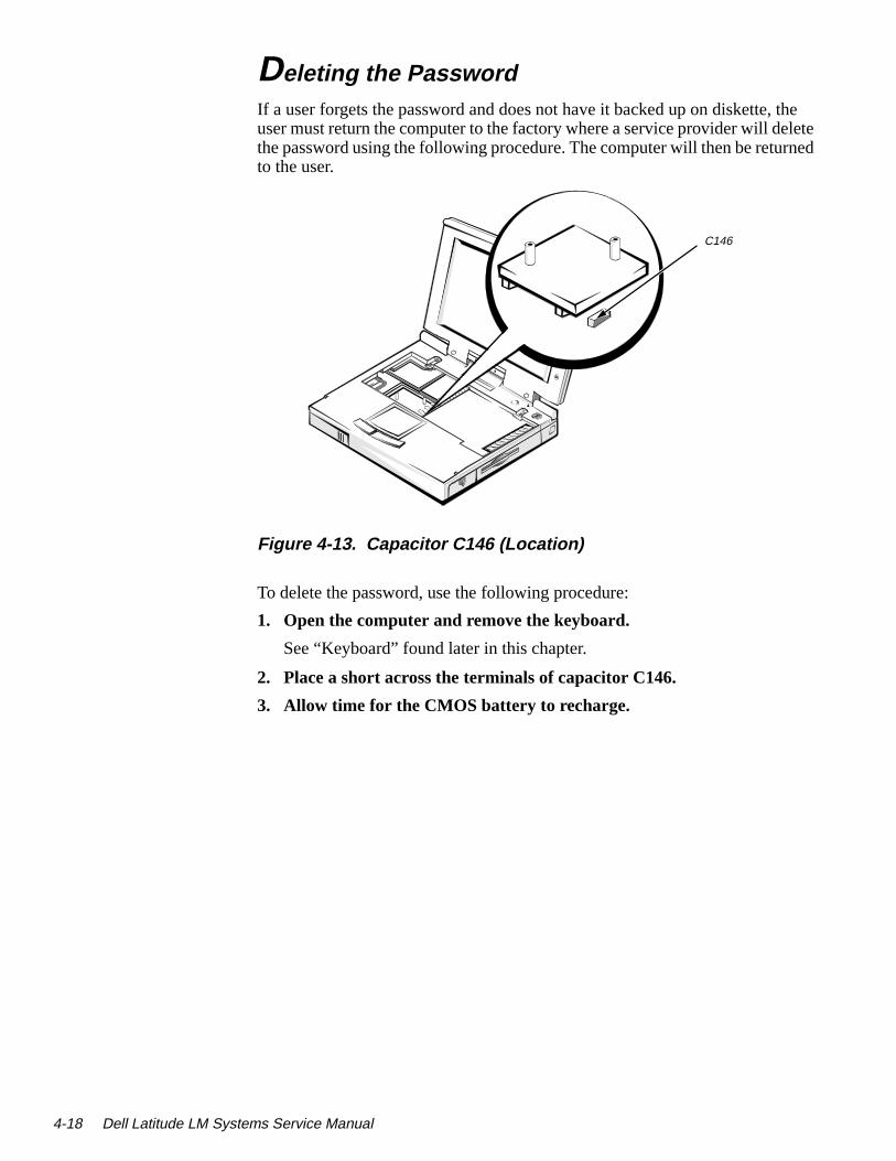
the elete rned
Deletin g the PasswordIf a user forgets the password and does not have it backed up on diskette,user must return the computer to the factory where a service provider will dthe password using the following procedure. The computer will then be retuto the user.
Figure 4-13. Capacitor C146 (Location)
To delete the password, use the following procedure:
1. Open the computer and remove the keyboard.
See “Keyboard” found later in this chapter.
2. Place a short across the terminals of capacitor C146.
3. Allow time for the CMOS battery to recharge.
C146
ms Service Manual

-disk ive he drive
er-
Hard-Disk Drive
Figure 4-14. Hard-Disk Drive Disassembly
The hard-disk drive resides in a carrier that mounts in the computer’s harddrive compartment on the front of the computer. Four screws secure the drinside the carrier. A mylar insulator provides electrical insulation between thard-disk drive and the rest of the computer. To disassemble the hard-diskfrom the carrier, follow these steps:
1. Remove the hard-disk drive assembly from the computer.
See step 5 of “Precautionary Measures” found earlier in this chapter.
2. Place the hard-disk drive assembly bottom side up on a work surface, and remove screws E1, E2, E3, and E4.
3. Remove the hard-disk drive from the carrier.
Gently pry the drive from the carrier with a small scribe.
4. Lift the hard-disk drive out of the bottom case.
Carefully pry the flex-cable connector away from the hard-disk drive intface connector on the back of the drive.
CAUTION: Use a small flat-blade screwdriver to disconnect theflex-cable connector. Do not handle the flex cable too roughly or youcould accidently disconnect the cable from the connector card ratherthan the drive.
carrier
E1E2
E3 E4
hard-disk drive
flex-cable connector
(screws E1–E6 are 4 mm)
E5
E6
4 mm
Removing and Replacing Parts 4-19
4-20 Dell Latitude LM Syste
on s a
Diskette Drive
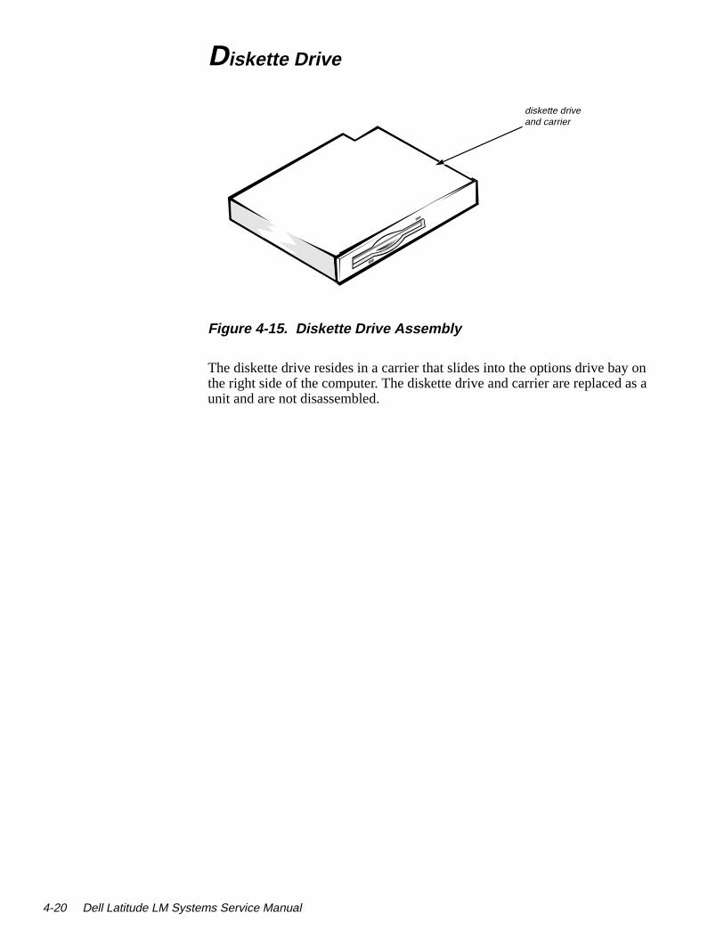
Figure 4-15. Diskette Drive Assembly
The diskette drive resides in a carrier that slides into the options drive bay the right side of the computer. The diskette drive and carrier are replaced aunit and are not disassembled.
diskette drive and carrier
ms Service Manual

he and
CD-ROM
Figure 4-16. CD-ROM Assembly
The CD-ROM resides in a carrier that slides into the options drive bay on tright side of the computer. The CD-ROM and carrier are replaced as a unitare not disassembled.
CD-ROM and carrier
Removing and Replacing Parts 4-21

4-22 Dell Latitude LM Syste
Memory Module.
Figure 4-17. Memory Module Removal
To remove a memory module, follow these steps:
1. Turn the computer over, and remove the two memory-module cover screws.
2. Remove the memory module cover.
Grasp the two memory-module retainer clips and release the memory mod-ule. Gently rotate the memory module toward you, and then pull straight up on the module, disconnecting the module from the connector on the main board assembly.
To reinstall a memory module, both memory modules must be a matched pair, both slots must be filled, and both slots must have the same memory capacity. The following combinations are possible:
• 16 MB — Install two 4-MB memory modules.
• 24 MB — Install two 8-MB memory modules.
• 40 MB — Install two 16-MB memory modules.
MM1
MM2 (screws MM1 and MM2 are 3.5 mm)
cover
retainer clip
memory module (2)
3.5 mm
ms Service Manual

ents. for
er-ft the to the
LCD AssemblyThe LCD assembly consists of the display assembly and its related componThe subsections that follow provide removal and replacement procedures the components of the LCD assembly.
Figure 4-18. LCD Assembly Removal
To remove the LCD assembly, follow these steps:
1. With the computer closed and the back facing you, remove the two hinge covers.
Pop off both of the covers with the heel of your palm; or insert your fingtips or a scribe between each cover and the LCD assembly, and then licovers sideways until they are released from the catches holding them computer.
2. Remove hinge screws H1, H2, H3, and H4.
3. Remove the flex-cable cover.
LCD assembly
hinge covers (2)H1H2
H3H4
flex-cable cover(screws H1–H4are 5 mm)
5 mm
Removing and Replacing Parts 4-23

4-24 Dell Latitude LM Syste
TFT
n
nd ides.
n lace.
Front Bezel
NOTE: This figure shows the STN LCD assembly, which has the same front bezel as theLCD assembly.
Figure 4-19. Front Bezel Removal
To remove the front bezel, follow these steps:
1. Remove the LCD assembly.
See the previous section, “LCD Assembly.”
2. With the front facing you, open the computer
3. Lay the LCD assembly back on a book or something similar to prop the assembly.
4. Use a scribe to pry the front-bezel screw covers out of the screw holes ithe bezel.
5. Remove front bezel screws H6 and H7.
6. Separate the front bezel from the back bezel.
Insert your fingertips in the crevice between the front and back bezel, alift up on the front bezel to release the hidden tabs spaced around the s
When replacing the front bezel, orient the bezel in its original position othe assembly and press firmly near each tab until the bezel snaps into p
bezel screw cover (2)
(screws H6 and H7 are 4.5 mm)
H6
H7
front bezel
hidden tabs4.5 mm
ms Service Manual

e he
s-
.
LCD PanelThere are two types of LCD panels: the dual-scan color display (STN) and thactive-matrix color display (TFT). The removal process for both LCD panels is tsame.
.
Figure 4-20. LCD Panel Removal
To remove an LCD panel, follow these steps:
1. Remove the front bezel.
See the previous subsection, “Front Bezel.”
2. Remove LCD panel screws H11, H12, H13, and H14.
3. Remove the LCD Panel.
NOTE: Be careful when removing any part of the LCD flex cable.
Lift up the LCD panel, and disconnect the LCD flex-cable connector. Diconnect the LCD panel cable from the upper inverter-board connector. Disconnect the LCD flex cable from the lower inverter-board connector
LCD panel
(screws H15 and H16 are 3 mm)
H11
H12
H13
H14
(screws H11–H14 are 6 mm)
LCD flex cable
power/ suspend indicator
6 mm
3 mm
inverter board
microphone
lower connector
upper connector
H15
H16
Removing and Replacing Parts 4-25

4-26 Dell Latitude LM Syste
ard.
Inverter Board
.
Figure 4-21. Inverter Board Removal
To remove the inverter board, follow these steps:
1. Remove the front bezel.
See “Front Bezel” found earlier in this section.
2. Remove the LCD panel.
See the previous subsection, “LCD Panel.”
3. Disconnect the power/suspend indicator connector.
4. Remove inverter board screws H15 and H16.
5. Remove the inverter board from the back bezel.
MicrophoneThe microphone cannot be removed separately; it is part of the inverter bo
inverter board
H15
H16
power/suspend indicator
(screws H15 and H16 are 3 mm)
3 mm
ms Service Manual
LCD Assembly Latches
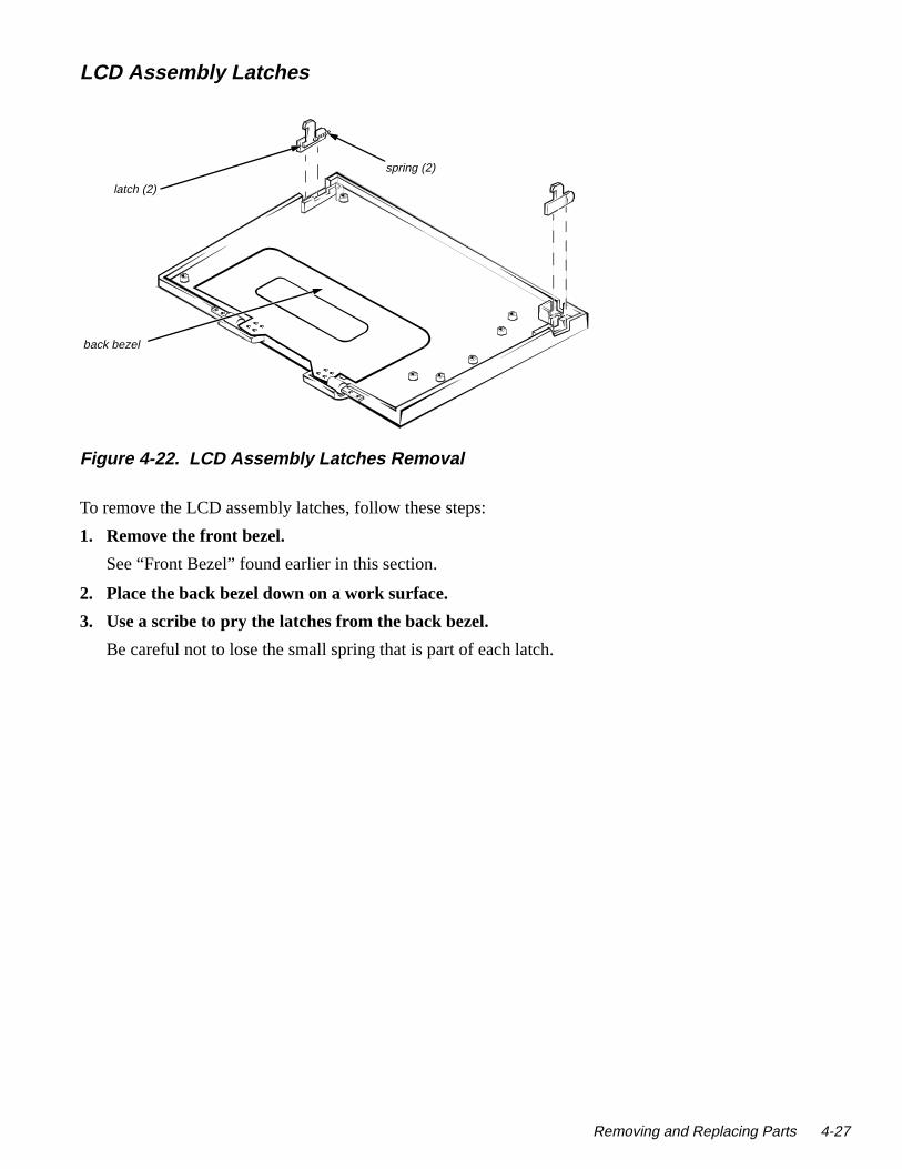
Figure 4-22. LCD Assembly Latches Removal
To remove the LCD assembly latches, follow these steps:
1. Remove the front bezel.
See “Front Bezel” found earlier in this section.
2. Place the back bezel down on a work surface.
3. Use a scribe to pry the latches from the back bezel.
Be careful not to lose the small spring that is part of each latch.
latch (2)
back bezel
spring (2)
Removing and Replacing Parts 4-27
4-28 Dell Latitude LM Syste
indi-
Power/Suspend Indicator
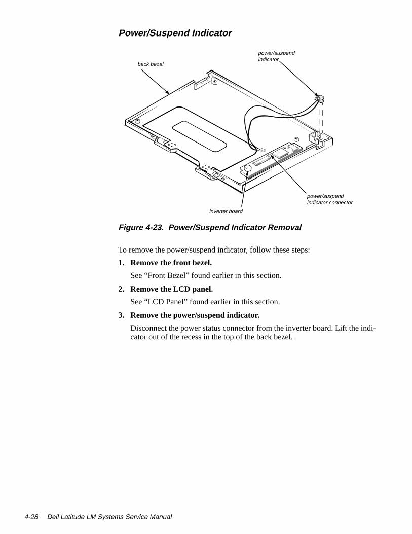
Figure 4-23. Power/Suspend Indicator Removal
To remove the power/suspend indicator, follow these steps:
1. Remove the front bezel.
See “Front Bezel” found earlier in this section.
2. Remove the LCD panel.
See “LCD Panel” found earlier in this section.
3. Remove the power/suspend indicator.
Disconnect the power status connector from the inverter board. Lift the cator out of the recess in the top of the back bezel.
power/suspend indicator
back bezel
power/suspend indicator connector
inverter board
ms Service Manual

Back Bezel
Figure 4-24. Back Bezel Removal
To remove the back bezel, follow these steps:
1. Remove the front bezel.
See “Front Bezel” found earlier in this section.
2. Remove the LCD panel.
See “LCD Panel” found earlier in this section.
NOTE: Be careful when removing any part of the LCD flex cable.
3. Remove the inverter board.
See “Inverter Board” found earlier in this section.
4. Remove the latches.
See “LCD Assembly Latches” found earlier in this section.
5. Remove the power/suspend indicator.
See the previous subsection, “Power/Suspend Indicator.”
back bezel
Removing and Replacing Parts 4-29

4-30 Dell Latitude LM Syste
des
tach-
KeyboardThis section provides the removal procedure for the keyboard. Also, it incluthe removal procedure for the heat sink.
Figure 4-25. Keyboard Removal
To remove the keyboard, follow these steps:
1. Open the computer.
2. Remove the keyboard screw covers.
3. Remove keyboard screws S1 and S2.
Lay the keyboard back against the LCD assembly or a prop to avoid deing the keyboard cable.
screw covers (2)
S1
S2
S4S3
heat sink
keyboard cable
main board
(screws S1 and S2 are 3 mm)
(screws S3 and S4 are 5.5 mm)
5.5 mm
3 mm
ms Service Manual

g the
4. Remove heat sink screws S3 and S4.
Lift off the heat sink.
5. Disconnect the keyboard cable from the main board.
Use a small flat-blade screwdriver to release the ZIF connector securinkeyboard cable.
6. Remove the keyboard from the computer.
CAUTION: Lift away the heat sink gently. Rough handling coulddamage the thermal pad on the bottom of the heat sink.
CAUTION: Lift away the cable only after the ZIF connector isopened (see “ZIF Connectors” found earlier in this chapter). Pullingthe cable from the connector damages the conductive coating on theend of the cable.
Removing and Replacing Parts 4-31

4-32 Dell Latitude LM Syste
nts. for
Production Note!!!
Top AssemblyThe top assembly consists of the plastic palm rest and its related componeThe subsections that follow provide removal and replacement procedures the components of the top assembly.
Figure 4-26. Top Assembly Removal
hinge cover (2)
keyboard
touch pad connector
main board
top assembly
bottom assembly
(screws SD1 andSD2 are 5 mm)
SD3
5 mm
SD4
hook
display close button
SD1
SD2
(screws SD3 andSD4 are 3 mm)
3 mm
ms Service Manual

in
ly hid-
ition tabs
in
ed to
To remove the top assembly, follow these steps:
1. Remove the LCD panel.
See “LCD Panel” found earlier in this chapter.
2. Remove the keyboard.
See the previous section, “Keyboard.”
3. Remove side screws SD1 and SD2.
4. Disconnect the touch pad connector.
Use a small flat-blade screwdriver to release the connector from the maboard.
5. Separate the top assembly from the bottom assembly.
Insert your fingertips or a scribe in the crevice between the top assemband the bottom assembly, and lift up on the top assembly to release theden tabs spaced around the sides, front, and back.
When replacing the top assembly, orient the assembly in its original poson the bottom assembly and press firmly near each tab until the hiddensnap into place.
6. Disconnect the status-display board connector.
Use a small flat-blade screwdriver to release the connector from the maboard. Release the wire bundle from the hook on the I/O bracket.
7. Remove the power supply board.
8. Disconnect the LCD flex-cable connector on the main board.
Remove flex-cable screws SD3 and SD4. There is a ground wire attachscrew SD4.
9. Remove the top assembly from the computer.
CAUTION: Do not attempt to remove the LCD flex cable from thetop assembly. The two connectors on the cable will not pass throughthe slot on the back of the top assembly.
Removing and Replacing Parts 4-33
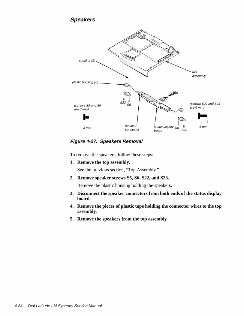
4-34 Dell Latitude LM Syste
y
p
Speakers
Figure 4-27. Speakers Removal
To remove the speakers, follow these steps:
1. Remove the top assembly.
See the previous section, “Top Assembly.”
2. Remove speaker screws S5, S6, S22, and S23.
Remove the plastic housing holding the speakers.
3. Disconnect the speaker connectors from both ends of the status displaboard.
4. Remove the pieces of plastic tape holding the connector wires to the toassembly.
5. Remove the speakers from the top assembly.
S5 (screws S22 and S23are 6 mm)
S6
plastic housing (2)
speaker (2)
speaker connector
status display board
top assembly
6 mm
(screws S5 and S6are 3 mm)
3 mm
S22
S23
ms Service Manual

-
n the
Status Display Board
Figure 4-28. Status Display Board Removal
To remove the status display board, follow these steps:
1. Remove the top assembly.
See “Top Assembly” found earlier in this section.
2. Remove status-display board screws S7, S8, and S9.
3. Disconnect the two speaker connectors and the infrared device connector from the status display board.
4. Disconnect the status display board connector from the main board.
The connector wire assembly is held in place by a metal hook located oI/O bracket.
5. Remove the status display board from the top assembly.
status display board
(screws S7–S9 are 6 mm)
speakerconnector (2)
infrared device connector
status-display board connector
S7
S8S9
top assembly
6 mm
Removing and Replacing Parts 4-35

4-36 Dell Latitude LM Syste
I/R Device
Figure 4-29. I/R Device Removal
To remove the infrared (I/R) device, follow these steps:
1. Remove the top assembly.
See “Top Assembly” found earlier in this section.
2. Disconnect the I/R device connector from the status display board.
3. Dislodge the I/R device from the recess on the top assembly.
Thread the I/R connector and wires through the opening on the top assembly.
4. Remove the I/R device from the top assembly.
top assembly
I/R connector
recess
I/R lens
ms Service Manual

Power Button
Figure 4-30. Power Button Removal
To remove the power button, follow these steps:
1. Remove the top assembly.
See “Top Assembly” found earlier in this section.
2. Remove the status display board.
See “Status Display Board” found earlier in this section.
3. Remove power button.
There are four plastic retainers that hold the power button and spring inplace.
4. Remove the power button and spring from the top assembly.
power button
spring
Removing and Replacing Parts 4-37

4-38 Dell Latitude LM Syste
e that
but-
Touch Pad
Figure 4-31. Touch Pad Removal
To remove the touch pad, follow these steps:
1. Remove the top assembly and turn it over.
See “Top Assembly” found earlier in this section.
2. Remove touch pad screws S11, S12, and S13.
Place the touch-pad button board to one side. The board has a flex cablattaches to the touch pad.
3. Remove the touch pad buttons.
Press down on the touch-pad button projections, and pull the touch padton out of the recess on the front of the top assembly.
4. Remove touch-pad bracket screws S14 and S15.
Remove the touch pad bracket.
5. Remove the touch pad bracket and touch pad from the top assembly.
top assembly
(screws S11–S15 are 3 mm)
S11S12
S13
S15S14
touch-pad button board
touch pad bracket
touch pad
flex cable
touch-pad cable connector
button (2)
3 mm
ms Service Manual

ain ce-
Bottom AssemblyThis bottom assembly consists of a plastic base, the main board, and the mboard components. The subsections that follow provide removal and replament procedures for the components of the bottom assembly.
Figure 4-32. Bottom Assembly
cache board
base
main board
audio board
power supply board
options bay wall
processor board
Removing and Replacing Parts 4-39

4-40 Dell Latitude LM Syste
tors.
Processor Board
Figure 4-33. Processor Board Removal
To remove the processor board, follow these steps:
1. Open the cover.
2. Remove the keyboard.
See “Keyboard” found earlier in this chapter.
3. Remove the processor board from the main board.
The processor board is held in place on the main board by two connecUse a chip removal tool to remove the processor board.
main board
processor board
processor board connector (2)
ms Service Manual

Power Supply Board
Figure 4-34. Power Supply Board Removal
To remove the power supply board, follow these steps:
1. Open the cover.
2. Remove the top assembly.
See “Top Assembly” found earlier in this chapter.
3. Remove the power supply board from the main board.
The power supply board is held in place on the main board by two connectors.
power supply board
main board
Removing and Replacing Parts 4-41

4-42 Dell Latitude LM Syste
ne oard s are
Audio Board
Figure 4-35. Audio Board Removal
To remove the audio board, follow these steps:
1. Open the cover.
2. Remove the top assembly.
See “Top Assembly” found earlier in this chapter.
3. Remove the cable from the audio board.
4. Remove the audio board from the main board.
The audio board is held in place on the main board by a connector on oside of the audio board. On the other side of the main board, the audio bis held in place by a clasp and two projections. The clasp and projectionon a plastic holder. Lift out the plastic holder.
audio board
main board
plastic holder
audio cable
audio boardconnector
ms Service Manual

Main Board
Figure 4-36. Main Board Removal
To remove the main board, follow these steps:
1. Open the cover.
2. Remove the top assembly.
See “Top Assembly” found earlier in this chapter.
3. Remove the power supply board.
See “Power Supply Board” found earlier in this section.
4. Remove the audio card.
See the previous subsection, “Audio Board.”
5. Remove the black mylar cover on the PC Card cage.
(screws S19– S20 are 5 mm)
(screws ST1–ST6are 6.5 mm)
(screw ST9 is 4 mm)
main board
I/O panel cover
S17
S16
S18S19
S20
ST9ST6
ST2ST3
ST4ST5
ST7
ST1
S8
I/O panel bracket
(screw S18 is 8 mm)
(screws ST7 and ST8 are 4.5 mm)
(screws S16 and S17 are 4 mm)
6 mm
5 mm
4 mm
4 mm
6.5 mm
4.5 mm
Removing and Replacing Parts 4-43
4-44 Dell Latitude LM Syste
and
con-.
6. Turn the computer around, open the I/O panel cover, and remove standoff nuts ST1, ST2, ST3, ST4, ST5, ST6, ST7, and ST8.
Use a 3/16 nut driver to remove standoff nuts ST1 through ST6 and a 7/32 nut driver for ST7 and ST8.
7. Remove cover alignment screws S16 and S17.
8. Remove main board screws S18, S19, S20, and ST9.
S18 has a corner brace that must be removed. ST9 is a standoff screwrequires a 5/32 nut driver.
9. Bend the options bay wall (see Figure 4-32).
Press gently on the ends of the wall just enough to free the option bay nectors on the main board. Be careful not to bend the wall in the middleWhen reinstalling the main board, bend the wall back to the vertical position.
10. Remove the main board.
Lift the end of the board nearest the front of the computer, and pull the board up and out of the computer.
ms Service Manual
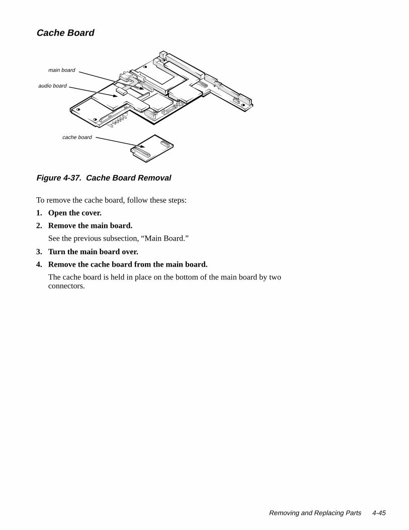
o
Cache Board
Figure 4-37. Cache Board Removal
To remove the cache board, follow these steps:
1. Open the cover.
2. Remove the main board.
See the previous subsection, “Main Board.”
3. Turn the main board over.
4. Remove the cache board from the main board.
The cache board is held in place on the bottom of the main board by twconnectors.
audio board
main board
cache board
Removing and Replacing Parts 4-45

4-46 Dell Latitude LM Syste
ms Service Manual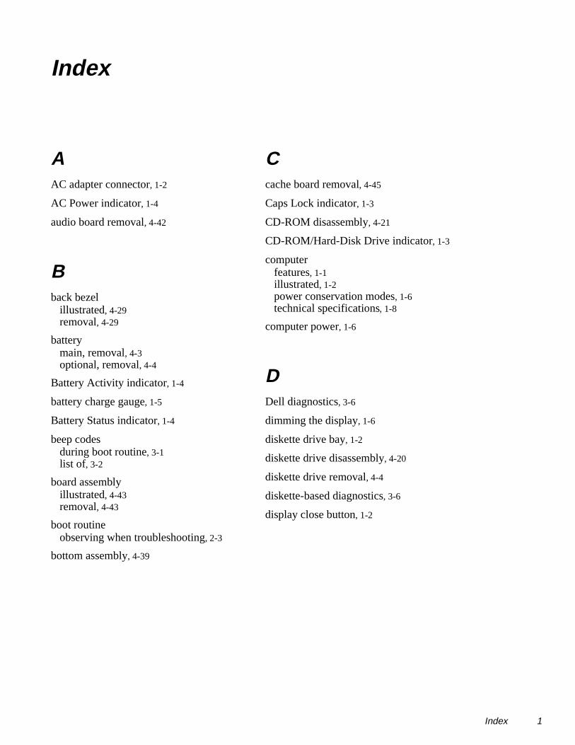
Index
AAC adapter connector, 1-2
AC Power indicator, 1-4
audio board removal, 4-42
Bback bezel
illustrated, 4-29removal, 4-29
batterymain, removal, 4-3optional, removal, 4-4
Battery Activity indicator, 1-4
battery charge gauge, 1-5
Battery Status indicator, 1-4
beep codesduring boot routine, 3-1list of, 3-2
board assemblyillustrated, 4-43removal, 4-43
boot routineobserving when troubleshooting, 2-3
bottom assembly, 4-39
Ccache board removal, 4-45
Caps Lock indicator, 1-3
CD-ROM disassembly, 4-21
CD-ROM/Hard-Disk Drive indicator, 1-3
computerfeatures, 1-1illustrated, 1-2power conservation modes, 1-6technical specifications, 1-8
computer power, 1-6
DDell diagnostics, 3-6
dimming the display, 1-6
diskette drive bay, 1-2
diskette drive disassembly, 4-20
diskette drive removal, 4-4
diskette-based diagnostics, 3-6
display close button, 1-2
Index 1

2 Index Temp
Eeliminating resource conflicts, 2-5
error messages, 3-3, 3-6
ESD, 4-3
expansion connector, 1-2
exploded viewbottom assembly, 4-10computer, 4-7LCD assembly, 4-8top assembly, 4-9
external video connector, 1-2
Ffactory repair parts and assemblies
list of, 4-11
field-replaceable parts and assemblies, 4-1,
4-7
front bezel removal, 4-24
Ggetting help, 2-5
Hhard-disk drive
location, 1-2removal, 4-19
headphones/speakers connector, 1-2
heat sink, 4-31
help, 2-5
II/O panel, 1-2
infrared device removal, 4-36
infrared port, 1-2
initial proceduresbeep codes, 3-1system error messages, 3-3troubleshooting, 2-1
initializationerror messages, 3-6
Internal Diskette-Drive Access indicator,
1-4
interrupt assignmentslist of, 1-7
inverter board removal, 4-26
Kkeyboard
location, 1-2removal, 4-30
keyboard/keypad/mouse connector, 1-2
LLCD assembly, 1-2
latch, 1-2removal, 4-23
LCD assembly latches removal, 4-27
LCD panel removal, 4-25
late

Mmain battery
location, 4-3removal, 4-3
main-battery compartment, 1-2
memorymaximum configuration, 1-1system memory, 1-1
memory modulecapacities supported, 1-1removal, 4-22
microphone, 1-2, 4-26
microphone jack, 1-2
microprocessor, 1-1
Nnaming conventions, 4-17
Num Lock indicator, 1-3
Ooptions bay, 1-2
PPad Lock indicator, 1-3
parallel port connector, 1-2
passwordabout, 1-5changing, 4-18
PC Carddoor, 1-2indicator, 1-4removal, 4-5
POST beep codesabout, 3-1list of, 3-2
powercomputer, 1-6
power buttonlocation, 1-2removal, 4-37
power conservation, 1-6
power status indicator, 1-2
power status indicator removal, 4-28
power supply board removal, 4-41
precautionary measures, 4-3
processor board removal, 4-40
Rremoval and replacement procedures
field-replaceable parts and assemblies, 4-1
precautionary measures, 4-3recommended tools, 4-1
resource conflictseliminating, 2-5
Sscrews
identification and tightening, 4-2
Scroll Lock indicator, 1-3
secondary battery removal, 4-4
serial port connector, 1-2
service tag number, 1-2
speaker removal, 4-34
specificationstechnical, 1-8
standby mode, 1-6
Index 3

4 Index Temp
status display board removal, 4-35
status display panelabout, 1-3location, 1-2
subsystemstesting, 3-6
suspend mode, 1-6
Suspend Mode indicator, 1-3
suspend-to-disk mode, 1-6
system error messagesabout, 3-3Dell diagnostics, 3-6list of, 3-3
system power, 1-6
Ttechnical specifications, 1-8
tools recommendedfield replaceable parts and assemblies,
4-1
top assembly removal, 4-32
touch padlocation, 1-2removal, 4-38
touch pad buttons, 1-2
troubleshootingboot routine, 2-3initial procedures, 2-1initial user contact, 2-1POST beep codes, 3-1running the Dell diagnostics, 3-6system error messages, 3-3visual inspection, 2-1
turning off the hard-disk drive, 1-6
Uuser contact
initial, 2-1
Vvisual inspection, 2-1
ZZIF connectors
disconnecting, 4-6reconnecting, 4-6
late