65-0321 01 - s7999d1048 combustion system operator ... ..... 53 udc controller application ..... 58...
TRANSCRIPT

PRODUCT DATA
65-0321-01
S7999D1048 Combustion System Operator Interface Display
APPLICATIONThe S7999D Combustion System Operator Interface (OI) reduces burner/boiler setup time by allowing the user to create a fuel/air modulation curve (profile) for ControLinks™ (Fuel/Air Ratio Control) that allows for safe and efficient operation at all points along the modulation curve. The OI uses a wizard like process to assist the user through the commissioning process. The S7999D can be used on systems with one or two fuels and on systems with or without flue gas re-circulation (FGR). The S7999D has two RS485 com ports that can be configured to provide:• Fuel/Air Ratio Control commissioning and monitoring• One or more boiler/burner systems monitoring (up to 99
burner/burner systems). Each burner control, Fuel/Air Ratio Control, and Expanded Annunciator present on each burner system can be viewed individually to determine its status.
• Local display to a System Monitor• System Monitor to one or more Local displays• Gateway for ModBus Master (BAS)
Universal Digital Controllers (UDC 2500/3200/3500 with modbus) can be used for several burner/boiler applications, and the S7999D can control the UDCs during their operation. Applications supported include:• Stack temperature• Water/steam PID load control• Steam/fuel flow monitoring• Thermal shock• Feed pump level control
The S7999D is a multiple language OI; English and Spanish selectable.
The S7999D can be flush mount or behind mounted into a panel cutout.
Wiring connections to the S7999D are through a removable 8-pin wiring connector.
The S7999D also has a USB port that can be used for:• Transfer screenshot images• Transfer Trend Analysis Reports• To upload:
(1) System OI application software revisions (when provided by Honeywell)
(2) Home page background image(3) Home page logo(4) Screen saver image
This document provides installation and initial setup instructions. Other applicable publications are:
• 66-1200 Combustion System Operator Interface Installation Instructions
Documents can be viewed or downloaded at: http://customer.honeywell.com
Contents
Specifications .................................................................... 2Safety Features ................................................................. 3Installing the Hardware ..................................................... 4Networking Options .......................................................... 5Getting started .................................................................. 11Starting the S7999 Display ............................................... 14Setting up the S7999D display ......................................... 15Fuel Air Ratio Control Commissioning .............................. 24Monitoring.......................................................................... 38
Set Hysteresis .................................................................. 42UDC Controllers ............................................................... 44Offline Profile Curve Builder ............................................. 48Renaming the Expanded Annunciator Terminals ............. 52Troubleshooting ................................................................ 53UDC Controller Application .............................................. 58

S7999D1048 COMBUSTION SYSTEM OPERATOR INTERFACE DISPLAY
65-0321—01 2
ORDERING INFORMATIONWhen purchasing replacement and modernization products from your TRADELINE® wholesaler or distributor, refer to the TRADELINE® Catalog or price sheets for complete ordering number. If you have additional questions, need further information, or would like to comment on our products or services, please write or phone:
1. Your local Honeywell Environmental and Combustion Controls Sales Office (check white pages of your phone directory).2. Honeywell Customer Care
1985 Douglas Drive NorthMinneapolis, Minnesota 55422-4386
3. http://customer.honeywell.com or http://customer.honeywell.caInternational Sales and Service Offices in all principal cities of the world. Manufacturing in Belgium, Canada, China, Czech Republic, Germany, Hungary, Italy, Mexico, Netherlands, United Kingdom, and United States.
FEATURES• Allows configuration of the R7999 ControLinks™
Controller.
• Allows monitoring of the R7999 ControLinks™ Controller.
• Allows monitoring of 7800 SERIES burner control.
• Allows monitoring of S7830 Expanded Annunciator.
• Allows monitoring and control of UDC2500/3200/3500 Universal Digital Controllers.
• Allows switching view between multiple burner systems.
• Dynamically locates attached burner systems (auto seeks).
• Allows 4-20 mA firing rate hysteresis adjustment.
• Allows Actuator control accuracy adjustment.
• Allows off-line profile curve building.
• Allows programmable expanded annunciator terminal naming.
• Allows burner system naming.
• Allows ControLinks™ R7999 EEPROM backup and restore.
• Real-time data trending analysis and transferring saved trend data to Excel spreadsheet
• 7” 800 x 480, 24 bit high resolution color LCD touch screen for clarity
• Audio output with integral speaker for sound output.
• Adjustable backlight control
• Real time clock with coin-cell battery back up (CR2032)
• Volume control
• Screen Capture function to capture screen images
• USB port for file transfers, screen shot images, and software updates
• Fuel/Air Ratio Control commission, S7999D acting as a System Monitor of multiple Local S7999D displays, 2 RS-485 (COM1 & 2) ports for Modbus™ interface to ControLinks, Universal Digital Controllers, and Burner controls and BAS Gateway.
• Windows® CE 6.0 Operating System
• 8-pin connector, back-up battery and mounting hardware are provided
SPECIFICATIONSElectrical Ratings: Input Voltage: 18 – 30 Vac (24Vac nomi-
nal), 50/60 HzInput Current: 500 mA maxPower consumption: 12W max
Operating Temperature: -4 to 158 ºF (-20 to 70 ºC)
Storage/Shipping Temperature: -22 to 176 ºF ( -30 to 80 ºC)
Humidity: 90% RH, non condensing
Enclosure rating: IP10 / NEMA 1
Approvals: FCC Part 15, Class A Digital Device Underwriter’s Laboratories, Inc. (UL) (cUL) Component Rec-
ognized (for non-continuous operation): File Number MH17367 (MJAT2, MJAT8.
Canada: ICES-003
Dimensions: See Fig. 1
Replacement Parts50063482-001 Bag assembly includes:• 8-pin connector• CR2032 coin battery• Mounting hardware• 3 clamp filters (1 for 24V power and 1 for each Modbus)

S7999D1048 COMBUSTION SYSTEM OPERATOR INTERFACE DISPLAY
3 65-0321—01
Fig. 1. S7999D dimensions in in. (mm).
NOTE: This equipment has been tested and found to comply with the limits for a Class A digital device, pursuant to part 15 of the FCC Rules. These limits are designed to provide reasonable protection against harmful interference when the equipment is operated in a commercial environment. This equipment generates, uses and can radiate radio frequency energy and, if not installed and used in accordance with the instruction manual, may cause harmful interference to radio communica-tions. Operation of this equipment in a residential area is likely to cause harmful interference in which case the user will be required to correct the interference at his own expense.
This Class A digital apparatus complies with Canadian ICES-003.Cet Appareil numérique de la classe A est conforme à la norme NMB-003 du Canada.
SAFETY FEATURESThe S7999D contains software that incorporates many features that are designed to guide you safely through the commissioning process. Safety, however, is your responsibility.
Read all documentation carefully and respond appropriately to all error messages.
Be aware that as you command the R7999 to open and close actuators, the R7999 is designed to prevent you from opening or closing them too rapidly. When any of the system actuators are below 20% of their open position, the R7999 effectively limits any actuator from traveling more than three degrees without moving the other actuators in the system. When all the actuators are over 20% of their open position, the limit increases to 10 degrees.
WARNINGExplosion Hazard.Improper configuration can cause fuel buildup and explosion.Operators of this display may move fuel and/or air actuators to positions that can create hazardous burner conditions. Improper user operation may result in PROPERTY LOSS, PHYSICAL INJURY or DEATH.
The S7999D System Display device is to be used only by experienced and/or licensed burner/boiler operators and mechanics.
M33567
[2] 3-1/2(89)
[4] Ø 3/16(5)
[2] 8-15/16(227)
4-9/16(116)
5-15/64(133)
7-3/64 (179)
9-7/16 (240)
6-21/32(169)
1-5/16(33)

S7999D1048 COMBUSTION SYSTEM OPERATOR INTERFACE DISPLAY
65-0321—01 4
INSTALLING THE HARDWARE
Mounting the S7999DThe S7999D can be mounted on the door panel of an electrical enclosure.
1. Select the location on the door panel to mount the dis-play; note that the device will extend into the enclosure at least one inch past the mounting surface.
2. Provide an opening in the panel door 8" wide X 5 1/2" high (for front panel mount) or 7 1/8" wide X 4 11/16" high (for rear panel mount). See Fig. 1 or use cutout tem-plates provided in Fig. 129 and Fig. 130.
3. Place the S7999D Display in the opening and use it as a template to mark the location of the four mounting screw holes. Remove the device.
4. Using pilot holes as guides, drill 1/4 in. holes through the door panel.
5. Place the display in the opening, aligning the mounting holes in the device with the drilled holes in the panel.
6. Secure the display to the panel with four #6-32 screws and nuts provided.
7. Wire the 24 Vac power supply and the RS-485 cables using the configuration and wiring diagrams in Fig. 3 to Fig. 9.
8. Ensure the 8-pin connector plug is aligned with the header pins when inserting the 8-pin connector plug back onto the Display. Secure firmly
Installing the ControLinks™ and Burner Control HardwareUse the following ControLinks™ instructions to install the system hardware: See Fig. 3 for wiring block diagram.
— 65-0238 R7999 ControLinks™ Control Controller.— 65-0239 ML7999 ControLinks™ Control Actuator.— 65-0240 Q7999 Wiring Subbase.— 65-0101 S7830 Expanded Annunciator.— 65-0249 S7810M Modbus™ Module.— 65-0084 Q7800 Wiring Subbase.— 65-0109 R78xx Flame Amplifier— 65-0089 ST7800 Purge Card— 65-0090 S7800 KDM— 65-0288 S7800A1142 KDM— 65-1085 7800 SERIES Relay Modules
Installing the Universal Digital Control HardwareUse the following documents to install the UDC2500, UDC3200, and UDC3500 hardware.
— 51-52-25-124 UDC2500 Quick Start Guide.— 51-52-03-36 UDC2500 Specification.— 51-52-25-127 UDC2500 Product Manual.— 51-52-25-129 UDC3200 Quick Start Guide.— 51-52-03-39 UDC3200 Specification.— 51-52-25-119 UDC3200 Product Manual.— 51-52-25-130 UDC3500 Quick Start Guide.— 51-52-03-40 UDC3500 Specification.— 51-52-25-120 UDC3500 Product Manual.
Refer to addendums at the end of this document for configuration parameters specifically designed for the application that the UDC controller provides.

S7999D1048 COMBUSTION SYSTEM OPERATOR INTERFACE DISPLAY
5 65-0321—01
NETWORKING OPTIONSThe S7999D has two communication ports (COM1, COM2) that can be set for:• Fuel/Air Ration Control only (Commission)• One or more boiler systems• Local display to a System Monitor• System Monitor to one or more Local displays• Gateway for Modbus master• Disable port (NOT USED)One of these COM port settings is selected for the S7999D in the Display Setup page. The COM port setup determines the role and scope that this S7999D has in the system.
COMMISSIONING THE FUEL/AIR RATIO CONTROLIn this setup one of the COM ports is set for Fuel/Air Ratio Control only (commission)
NOTE: The port baud rate must be set for 4800.
The other COM port has several options or can be disabled. In the example below, the other COM port has been set up for one or more boiler system. (See Fig. 2 & 3 for examples).
Fig. 2. Example for commissioning the Fuel/Air Ratio Control.
The S7999D can connect directly to the R7999 from the COM port that has been set up for Fuel/Air Ratio Control only (commission); baud rate set to 4800, using the cable and installation procedures specified in the R7999 Product Data Sheet. The R7999 can remain connected to to this COM port following commissioning.
The Modbus™ network on the COM port setup for One or more boiler systems (ensure the port baud rate matches the ModBus baud rate and the port Modbus addressing range covers the range of addresses of the Modbus devices on the network) consists of wiring the S7810M devices together as slaves to the S7999D. An S7810M device is required for each burner/boiler system. Up to 99 burner/boiler systems can be connected in this configuration (unless other slave devices are included in the Modbus™ wiring). Fig. 3 depicts this wiring.
S7810MMODBUS
RM78xxBURNER
CONTROL
S7830EXPANDED
ANNUNCIATOR
R7999FUEL AIR
RATIO CONTROL
R7999FUEL AIR
RATIO CONTROL
S7830EXPANDED
ANNUNCIATOR
RM78xxBURNER
CONTROL
RM78xxBURNER
CONTROL
S7800
S7810MMODBUS
S7999DSYSTEM DISPLAY
CONTROLBUS
FCI
M33553
COM 1 or COM 2
COM 1 or COM 2MASTER
SLAVE
S7810MMODBUS CONTROLBUS
SLAVE
SLAVE
UP TO 99BURNER/BOILER
SYSTEMS
S7800 KEYBOARD DISPLAY CONFIGURED FOR MODBUS.1
MODBUS BAUD RATE MUST BE SET FOR EITHER 9600 OR 19200 FOR THE S7810M AND THE S7800 CONFIGURED FOR MODBUS MODE.
2
F/A Ratio Control BAUD RATE IS 4800.3
THE R7999 F/A Ratio Control CONNECTED THROUGH THE S7810M MODBUS CAN BE MONITORED BY THE S7999 DISPLAY, BUT IT CANNOT BE COMMISSIONED IN THIS LOCATION.
4
1
3
4
2

S7999D1048 COMBUSTION SYSTEM OPERATOR INTERFACE DISPLAY
65-0321—01 6
Fig. 3. Wiring diagram for commissioning the Fuel/Air Ratio Control example.
ONE OR MORE BOILER SYSTEMSThe S7999D manages a series of Modbus™ nodes (up to 99 addresses) consisting of 7800 SERIES Burner Controls, ControLinks™, and UDC devices (see Fig. 2).• Addressing the Modbus™ nodes or systems
In the One or More Boiler Systems setup, addressing the Modbus™ nodes is done manually, and careful Modbus™ addressing is required because duplicate addresses aren't allowed. Manual assignment of UDC controllers to their respective systems is required.
M33873
CONTROLINKS CONTROLLER
R7999
A B C
A B C A B C COM POWER
S7999D OI DISPLAY
3
1
S7810MMODBUS MODULE
C A B
6 7 8
2
“C” TERMINALS ARE CONNECTED INTERNALLY TO 24 VAC “COM”. 3
SEE 65-0249 FOR MULTIPLE S7810M NETWORK CONNECTIONS.4
MODBUS BAUD RATE MUST BE SET FOR EITHER 9600 BAUD OR 19200 BAUD. 5
SEE 65-0238 FOR R7999 WIRING.6
120 Ω, 1/4 WATT RESISTOR BETWEEN TERMINALS A AND B OF THE MODBUS AT THE FARTHEST S7810M MAY BE NECESSARY FOR LONG RS-485 RUNS.
7
4
5
CONNECT SHIELD TO EARTH GROUND.1
SEE 65-0249 FOR CONTROL BUS (LOCAL RS-485 COMMUNICATION BUS) WIRING.2
1
COM 1 COM 2 24 VAC3
8TO PROTECT AGAINST CONDUCTED AND RADIATED TRANSIENT NOISE, USE CLAMP FILTERS (INCLUDED IN 50063482-001 BAG ASSEMBLY) AS ILLUSTRATED IN FIGURES ON PAGE 2.
9 BAUD RATE COMMISSIONING THE FUEL/AIR RATIO CONTROL MUST BE SET FOR 4800 BAUD.
8
9120V

S7999D1048 COMBUSTION SYSTEM OPERATOR INTERFACE DISPLAY
7 65-0321—01
Fig. 4. Example for One or more boiler systems.
UDC controllers may be added to the Modbus network (see Fig. 4). The UDC controllers share the Modbus™ with the S7810M devices, so the total number of burner/boiler systems
is reduced by the number of UDC controllers on the network. A combined total of 99 devices are permitted on the Modbus™ network. Wiring for this configuration is shown in Fig. 5.
S7810MMODBUS
RM78xxBURNER
CONTROL
S7830EXPANDED
ANNUNCIATOR
R7999FUEL AIR
RATIO CONTROL
S7830EXPANDED
ANNUNCIATOR
RM78xxBURNER
CONTROLUDC2500THERMAL
SHOCK
S7810MMODBUS
S7999DSYSTEM DISPLAY
CONTROLBUS
M33555
COM 1 or COM 2MASTER
SLAVE
S7810MMODBUS
UP TO 99BURNER/BOILERSYSTEMS AND
UDC CONTROLLERS
CONTROLBUS
SLAVE
SLAVE
UDC2500PID LOADCONTROL
SLAVE
UDC2500STEAM/FUEL
FLOW
SLAVE
SLAVE RM78xxBURNER
CONTROL
S7800 1
S7800 KEYBOARD DISPLAY CONFIGURED FOR MODBUS.1
MODBUS BAUD RATE MUST BE SET FOR FOR EITHER 9600 OR 19200 BAUD RATE.2
2

S7999D1048 COMBUSTION SYSTEM OPERATOR INTERFACE DISPLAY
65-0321—01 8
Fig. 5. Example wiring diagram for one or more boiler systems with UDC Controller.
Manual assignment of the UDC controllers to their associated burner/boiler system is required to allow UDC controllers on the S7810 Modbus™ network. No automatic assignment is possible.
Careful Modbus™ addressing is required when inserting UDC controllers in this configuration since duplicate addresses aren't allowed. Default Modbus™ addresses for the UDC controllers may need to be changed for them to work properly in the network.
SYSTEM MODES7999D manages a series of (up to 99) local systems in a S7999D Modbus™ network (see Fig. 8). In the System configuration, Modbus™ addresses of the nodes are learned by the System S7999D, so manual assignment isn’t necessary. Be sure not to duplicate Modbus™ addresses in the nodes.
UP TO A TOTAL OF 99 S7810M AND UDC CONTROLLERS CAN BE CONNECTED TO THE S7999D. SEE 65-0249 AND UDC MANUALS FOR WIRING.
M33556
CONTROLINKS CONTROLLER
R7999
A B C
A B C A B C COM POWER
S7999D OI DISPLAY
3
1
“C” TERMINALS ARE CONNECTED INTERNALLY TO 24 VAC “COM”. 3
4
MODBUS BAUD RATE MUST BE SET FOR EITHER 9600 0R 19200 BAUD RATE.5
SEE 65-0238 FOR R7999 WIRING.6
120 Ω, 1/4 WATT RESISTOR BETWEEN TERMINALS A AND B OF THE MODBUS AT THE FARTHEST S7810M MAY BE NECESSARY FOR LONG RS-485 RUNS.
7
CONNECT SHIELD TO EARTH GROUND.1
SEE 65-0249 FOR CONTROL BUS (LOCAL RS-485 COMMUNICATION BUS) WIRING.2
1
COM 1 COM 2 24 VAC3
S7810MMODBUSMODULE
B
A
C
8
7
6
2
4
UDCCONTROLLER
D-
D+
SHLD 16
17
18
5 7

S7999D1048 COMBUSTION SYSTEM OPERATOR INTERFACE DISPLAY
9 65-0321—01
Fig. 6 depicts the configuration when this S7999D is a subsystem of the System Modbus™ burner system network.
Fig. 6. Local S7999D with connection to System Modbus™ network.
In this configuration, the Local S7999D is a Modbus™ slave to the S7999D that has the system view perspective (System S7999D). Data about the local burner system is made available to the System S7999D when it accesses the interface registers in the Local S7999D.
The Local S7999D automatically detects UDC controllers connected to its network and displays them on the Home page as they are found. No user involvement is necessary at the S7999D to make the UDC controller visible to it.
The application type or function of the UDC controller is automatically determined by the Local S7999D.
Each Local burner/boiler system can be designated as either a burner system or a boiler system. This designation is specified in the Local S7999D. Each system can also be named. This system (equipment) name is displayed on the Home page. You can quickly search for the S7810M and UDC controllers on the Local Modbus™ network.
Fig. 7. Local S7999D with connection to System Modbus™ network wiring.
S7810MMODBUS
RM78xxBURNER
CONTROL
S7830EXPANDED
ANNUNCIATOR
R7999FUEL AIR
RATIO CONTROL
UDC2500THERMAL
SHOCK
S7999DSYSTEM DISPLAY
COM 1 ORCOM 2
M33562B
S7999DSYSTEM DISPLAY
COM 1 OR COM 2
SYSTEM S7999D
LOCAL S7999D
SYSTEMMODBUS
COM 1 ORCOM 2MASTER
MASTER
SLAVE
SLAVE
LOCALMODBUS
CONTROLBUS
SLAVE
UDC2500STACK
TEMPERATUREUDC2500FEED PUMP
LEVEL CONTROL
SLAVE
UDC2500PID LOADCONTROL
SLAVE
UDC2500STEAM/FUEL
FLOW
SLAVE
SLAVE
2
1
MODBUS BAUD RATE MUST BE SET FOR EITHER 9600 OR 19200.1
ANY MODBUS BAUD RATE CAN BE USED; HOWEVER THE SELECTED BAUD RATES MUST MATCH.2
UDC2500STACK
TEMPERATURE
UP TO A TOTAL OF 99 S7810M AND UDC CONTROLLERS CAN BE CONNECTED TO THE S7999D. SEE 65-0249 AND UDC MANUALS FOR WIRING.
M33563
A B C A B C COM POWER
LOCAL S7999D
3
“C” TERMINALS ARE CONNECTED INTERNALLY TO 24 VAC “COM”. 3
4
MODBUS BAUD RATE MUST BE SET FOR 19200 (COM2) AND 4800 (COM1).5
MAKE SURE 24 VAC POWER SUPPLY TO EACH S7999D ARE CONNECTED IN PHASE (OBSERVE TRANSFORMER PRIMARY AND SECONDARY WINDING POLARITIES).
6 120 Ω, 1/4 WATT RESISTOR BETWEEN TERMINALS A AND B OF THE MODBUS AT THE FARTHEST S7810M MAY BE NECESSARY FOR LONG RS-485 RUNS.
7
CONNECT SHIELD TO EARTH GROUND.1
SEE 65-0249 FOR CONTROL BUS (LOCAL RS-485 COMMUNICATION BUS) WIRING.2
1
COM 1 COM 2 24 VAC3
S7810MMODBUSMODULE
B
A
C
8
7
6
2
4
D-
D+
SHLD 16
17
18
5 7
A B C A B C COM POWER
SYSTEM S7999D
3COM 1 COM 2 24 VAC3 7 7

S7999D1048 COMBUSTION SYSTEM OPERATOR INTERFACE DISPLAY
65-0321—01 10
System S7999D ConfigurationThe S7999D can be configured to monitor all burner/boiler systems via a System Modbus™ network. One S7999D is designated the System S7999D (master) on the network, and the other S7999Ds are designated as a Local S7999D (slave) to provide system status for their respective burner/boiler system.
Fig. 8 depicts this type of configuration. Only S7999Ds are wired together in this configuration (using either COM port).
Only one S7999D can be configured as the System S7999D on this Modbus™ network. This S7999D assumes the Modbus™ master role on the selected COM port. Only the System S7999D can view any burner/boiler system on the network; the Local S7999D can only view its own burner/boiler system.
Fig. 8. System Modbus™ network.
Up to 99 Local burner/boiler systems can be connected together and displayed at the System S7999D.
A Modbus™ register interface is used in the Local S7999D to provide status data to the System S7999D. Many of the register addresses and definitions for the burner control, expanded annunciator, and R7999 have the same definitions that the S7810M specifies in its interface.
At the System S7999D a quick search for Local S7999Ds on the System Modbus™ network can be performed. This function is expected to be used after a new Local burner/boiler system is attached to the System Modbus™ network. If the quick search isn’t done, a slower, automatic search eventually finds new Local burner/boiler systems.
R7999FUEL AIR
RATIO CONTROL
S7830EXPANDED
ANNUNCIATOR
RM78xxBURNER
CONTROL
S7810MMODBUS
S7999DSYSTEM DISPLAY
S7999DSYSTEM DISPLAY
CONTROLBUS
COM 1 OR COM 2
M33564C
MASTER
SLAVE
SYSTEM MODBUS
LOCAL MODBUS
SYSTEM S7999D
LOCAL S7999D
UP TO 99LOCAL S7999D
SYSTEMS
UDC2500THERMAL
SHOCK
UDC2500PID LOADCONTROL
UDC2500FEED PUMP
LEVEL CONTROL
UDC2500STACK
TEMPERATURE
UDC2500STEAM/FUEL
FLOW
R7999FUEL AIR
RATIO CONTROL
S7830EXPANDED
ANNUNCIATOR
RM78xxBURNER
CONTROL
S7810MMODBUS
S7999DSYSTEM DISPLAY
CONTROLBUS
SLAVE
LOCAL MODBUS
LOCAL S7999D
UDC2500THERMAL
SHOCK
UDC2500PID LOADCONTROL
UDC2500FEED PUMP
LEVEL CONTROL
UDC2500STACK
TEMPERATURE
UDC2500STEAM/FUEL
FLOW
R7999FUEL AIR
RATIO CONTROL
S7830EXPANDED
ANNUNCIATOR
RM78xxBURNER
CONTROL
S7810MMODBUS
S7999DSYSTEM DISPLAY
CONTROLBUS
SLAVE
LOCAL MODBUS
LOCAL BURNER/BOILER SYSTEM
LOCAL BURNER/BOILER SYSTEM
LOCAL BURNER/BOILER SYSTEM
LOCAL S7999D
UDC2500THERMAL
SHOCK
UDC2500PID LOADCONTROL
UDC2500FEED PUMP
LEVEL CONTROL
UDC2500STACK
TEMPERATURE
UDC2500STEAM/FUEL
FLOW
2
2
2
2
1
1
1
MODBUS BAUD RATE MUST BE SET FOR EITHER 9600 OR 19200.1
ANY MODBUS BAUD RATE CAN BE USED; HOWEVER THE SELECTED BAUD RATES MUST MATCH.2
COM 1 OR COM 2
COM 1 OR COM 2
COM 1 OR COM 2
COM 1 OR COM 2
COM 1 OR COM 2
COM 1 OR COM 2

S7999D1048 COMBUSTION SYSTEM OPERATOR INTERFACE DISPLAY
11 65-0321—01
Fig. 9. System Modbus™ network wiring.
GETTING STARTED1. Make sure the S7999D 8-pin connector is properly
aligned and pressed firmly in place.2. Make sure the wires between the 8-pin connector and
the controller are properly wired and secured.3. Make sure the power supply is connected securely to the
power source.
WARNINGElectrical Shock Hazard.Can cause severe injury, death or equipment damage.Line voltage is present at the 120 Vac power supply.
THE AVAILABLE COM PORT CAN BE CONNECTED TO EITHER A FUEL/AIR RATIO CONTROL SYSTEM (COMMISSION) OR ONE S7810M MODBUS MODULE.
M33565B
A B C A B C COM POWER
3
“C” TERMINALS ARE CONNECTED INTERNALLY TO 24 VAC “COM”. 3
4
MAKE SURE 24 VAC POWER SUPPLY TO EACH S7999D ARE CONNECTED IN PHASE (OBSERVE TRANSFORMER PRIMARY AND SECONDARY WINDING POLARITIES).
EITHER COM PORT CAN BE USED; ENSURE THE BAUD RATE FOR EACH COM PORT MATCHES.
5
CONNECT SHIELD TO EARTH GROUND.1
SEE 65-0249 FOR CONTROL BUS (LOCAL RS-485 COMMUNICATION BUS) WIRING.2
4
COM 1 COM 2 24 VAC3
A B C A B C COM POWER
SYSTEM S7999D OI DISPLAY
3COM 1 COM 2 24 VAC3 5
5
1
N L
1
1
A B C A B C COM POWER
LOCAL S7999D OI DISPLAY
3COM 1 COM 2 24 VAC3 5
4
1
N L
LOCAL S7999D OI DISPLAY
6
6
6
6

S7999D1048 COMBUSTION SYSTEM OPERATOR INTERFACE DISPLAY
65-0321—01 12
WiringThe S7999D Display must be appropriately wired for both power and communications.
An external 24Vac power source must be supplied for the S7999D OI.
The communication is done over two RS-485 bus ports: • COM1 and COM2 are universal and can be configured to
provide:— Fuel/Air Ratio Control commissioning and monitoring— One or more boiler/burner systems monitoring (up to
99 burner/burner systems). Each burner control, Fuel/Air Ratio Control, and Expanded Annunciator present on each burner system can be viewed individually to determine its status.
— Local display to a System Monitor— System Monitor to one or more Local displays— Gateway for ModBus Master (BAS)
Fig. 10. S7999D connector terminals.
*These 3 terminals are connected internally and can be con-nected to earth ground
The S7999D communicates with the UDC controllers via a 3-wire RS-485 interface using the Modbus™ protocol.
The System S7999D communicates with Local S7999Ds via a 3-wire RS-485 interface using the Modbus™ protocol.
The S7999D is compatible with R7999 build 140 and newer, and with S7810M build 6020 and newer.
Fig. 11. S7999D basic wiring diagram
In this example, COM 1 is configured for commission fuel/Air Ratio Control (the Baud rate must be set for 4800), and COM 2 is configured for one or more burner/burner systems monitoring. The Baud rate must match the selected Baud rate of the S7810M ModBus Module. For network wiring and setup of the R7999, RM7800/S7810M, S7830 and UDC2500/3200/3500 with the S7999D, refer to 65-0231.
Table 1. 8-pin Connector Terminals.
Pin # Function
1 COM1 A
2 COM1 B
3 COM1 C*
4 COM2 A
5 COM2 B
6 COM2 C*
7 24 Vac Common *
8 24 Vac Power
M33566
A B C A B C COM POWER
COM 1 COM 2 24 VAC
M33554A
CONTROLINKS CONTROLLER
R7999
A B C
A B C A B C COM POWER
S7999D OI DISPLAY
3
1 6
7S7810MMODBUS MODULE
C A B
6 7 8
2
“C” TERMINALS ARE CONNECTED INTERNALLY TO 24 VAC “COM”. 3
SEE 65-0249 FOR MULTIPLE S7810M NETWORK CONNECTIONS.4
MODBUS BAUD RATE SET FOR EITHER 9600 OR 19200.
RS485 WIRING: MAXIMUM 4,000 FEET WITHOUT RS485 REPEATERS.
THE S7810M MODBUS MODULE MUST BE CONNECTED TO A 7800 SERIES BURNER CONTROL. (THE 7800 SERIES BURNER CONTROL GENERATES THE START BIT FOR THE MODBUS POLLING OF THE MEMBERS ON THE LOCAL MODBUS NETWORK).
5
SEE 65-0238 FOR R7999 WIRING.6
120 Ω, 1/4 WATT RESISTOR BETWEEN TERMINALS A AND B OF THE MODBUS AT THE FARTHEST S7810M MAY BE NECESSARY FOR LONG RS-485 RUNS.
7
4 10
5
CONNECT SHIELD TO EARTH GROUND.1
SEE 65-0249 FOR CONTROL BUS (LOCAL RS-485 COMMUNICATION BUS) WIRING.2
1
COM 1 COM 2 24 VAC3
8TO PROTECT AGAINST CONDUCTED AND RADIATED TRANSIENT NOISE, USE CLAMP FILTERS (INCLUDED IN 50063482-001 BAG ASSEMBLY) AS ILLUSTRATED IN FIGURES 2 AND 3.
8
9
10
9
9
120V
S7999D1048 COMBUSTION SYSTEM OPERATOR INTERFACE DISPLAY
13 65-0321—01
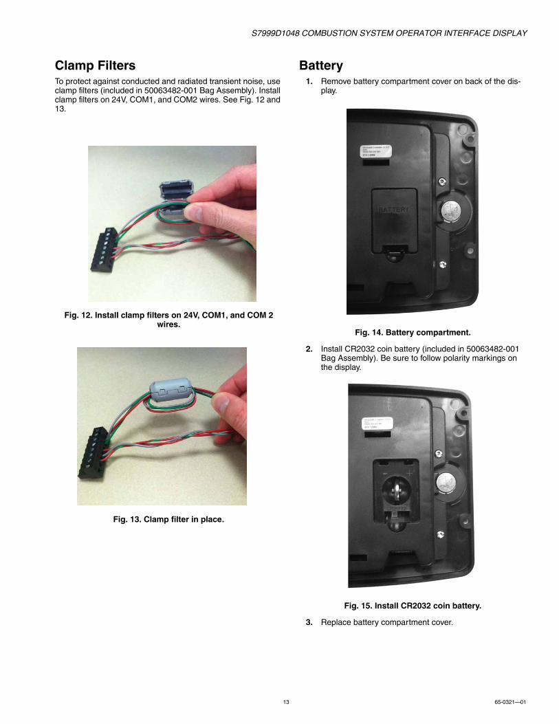
Clamp FiltersTo protect against conducted and radiated transient noise, use clamp filters (included in 50063482-001 Bag Assembly). Install clamp filters on 24V, COM1, and COM2 wires. See Fig. 12 and 13.
Fig. 12. Install clamp filters on 24V, COM1, and COM 2 wires.
Fig. 13. Clamp filter in place.
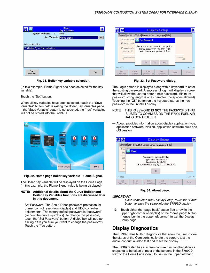
Battery1. Remove battery compartment cover on back of the dis-
play.
Fig. 14. Battery compartment.
2. Install CR2032 coin battery (included in 50063482-001 Bag Assembly). Be sure to follow polarity markings on the display.
Fig. 15. Install CR2032 coin battery.
3. Replace battery compartment cover.

S7999D1048 COMBUSTION SYSTEM OPERATOR INTERFACE DISPLAY
65-0321—01 14
STARTING THE S7999 DISPLAY
Home PageThe Home page will appear when the device is properly powered. Make sure a screen similar to Fig. 17, 18, or 18 appears after the S7999D is completely powered up. Select the setup button to adjust backlight and sound as desired and for other setup function. If the screen is dim, check Pin 7 and 8 wiring connection.
The Home page is the main screen that leads to all other pages and is used to select one of the following actions:
• Commission the ControLinks™ Fuel/Air Ratio Control:• Touch the Fuel/Air Ratio icon and then the
Commission Button to start commissioning a new system or modify/review the commission settings of an existing systems.
NOTE: ControLinks™ Fuel/Air Ratio Control (R7999) can only be commissioned when it is attached to a COM port (COM 1 or COM 2) that has been setup for Fuel/Air Ration control only (Commission). The Baud rate of this COM port must be set for 4800.
• Monitor a burner system:• Touch the icon (Burner Control, Fuel/Air Ratio
Control, UDC) corresponding to the part of the system you wish to monitor. Press the Fuel/Air Control Configuration button to view more parameter settings of the Fuel/Air Ratio control.
• Monitor application controller.• S7999D Setup and Diagnostics.
• Touch the setup button to access the display settings (General setup, Com Port setup, Screen Saver, Language selection, Home Page Title, Date/Time), Display Diagnostics (Com port status, Screen calibrations, Audio & Video tests, Display reset) Screen Snapshot (view snapshots, transfer snapshots to USB) and other tools (Curve Builder, Boiler Key Varibles, Password setting, Control Setup, Synchronize).
NOTE: Be sure to touch the Save Button to ensure new settings become effective.
• The “camera” icon in the upper left corner is for screen snapshot use. Up to 16 snapshots can be stored in the display and can be copied to a USB memory stick.
The number of actuators displayed on this page will vary depending on the number of actuators previously wired to the ControLinks™ Fuel/Air Ratio Control and configured via the S7999D configuration tool.
Fig. 16. Home Page - no connection.
Fig. 17. Home Page - connected.
No title is displayed on this page unless specified in "Title" tab in the display Setup page. The custom title entered by the user is displayed on the page when selected by the user.
A burner or boiler icon displays on the page designating which type of system it represents. The user chooses which type of system it is in display Setup.
If the screen is blank (Fig. 16) with no device icon or the icons are greyed out (Fig. 18), then no R7999 and no burner systems are seen by the S7999D. Check for proper wiring connections and make necessary corrections.
Fig. 18. Home Page—disconnected.

S7999D1048 COMBUSTION SYSTEM OPERATOR INTERFACE DISPLAY
15 65-0321—01
SETTING UP THE S7999D DISPLAY
1. At Home Page, touch Setup Button. The Setup Page is displayed.
Fig. 19. Setup Page.
2. At Setup Page, touch Display Setup Button. The Display Setup Page is displayed.
Fig. 20. Display Setup Page.
3. At Display Setup, touch Set Date/Time Button. The Set Date/Time Page is displayed. On the “General” tab, the Volume level (for touch audio feedback and alarm), Back-light intensity, Sound alarm for faults, Installation type (icon displayed [Burner system or Boiler system] when IO is connected to a network of multiple burner/boiler controls) can be adjusted.
Fig. 21. Set Date/Time Page.
4. Set the Date and Time and touch OK.5. When the “Sound audio alarm for fault?” box is checked,
the internal speaker of the S7999D will be activated and a 2-tone alarm will sound whenever a fault occurs in one of the controllers connected to the S7999D. Use the vol-ume slider bar to adjust the volume level. Also an “alarm bell” icon will be displayed in the lower left hand corner of the screen. (See Fig. 22). Touching the “alarm bell” icon or touching the “OK” button, in the Fault dialog box will turn off the S7999D audio alarm for the current fault.
Un-checking the “Sound audio alarm for fault?” box will deactivate the audio alarm function.
Fig. 22. Home Page With Active Alarm.
6. Select Com 1 Tab to setup Com 1 port. In this example, Com 1 has been setup for commissioning of the Contro-Links R7999 F/A ratio controller (the baud rate will default to 4800 baud, this baud rate is required to be able to commission ControlLinks).

S7999D1048 COMBUSTION SYSTEM OPERATOR INTERFACE DISPLAY
65-0321—01 16
Fig. 23. COM 1 tab.
7. Select Com 2 Tab to setup Com 2. In this example, Com 2 has been set to monitor one or more boiler sys-tems. The baud rate must match the baud settings of the S7810M (9200 baud or 19200 baud). Ensure the Mod-bus Address range is set high enough for the address(es) of the S7810M Modbus Module(s) con-nected to Com 2. Up to 99 Modbus addresses (S7810M Modbus Modules or combination S7810M Modbus Mod-ules and UDC controllers) can be monitored by one S7999D.
Fig. 24. COM 2 tab.
8. The other Com port selections provide:
— Local display to a System Monitor: when this option is selected, the Com port then becomes a Modbus slave to a System Monitor, see Fig 9. In this figure the Local S7999D IO display would be the Modbus slaves in the Mobus network. Com 1 of each of the Local displays would be configured for, “Local display to a System Monitor”. Note that each of the Local displays must have a unique Modbus address. When using this option, the Starting Modbus address, in the Modbus address range, becomes the Modbus address for the Com port. Touch the starting address box to set Modbus address. The port baud rate can be set for any baud rate. However, all the baud rates of the Local displays and the System Monitor dis-play must be the same. Touch the port baud rate box to set the baud rate. The other Com port can be configured for “Fuel/Air Ratio control only (Commission)” or “One or more boiler systems”.
NOTE: If the Com port is configured for “One or more boiler systems,” the local display is limited to only one S7810M Modbus module connected to the Com port.
— System Monitor to one or more Local displays: when this option is selected the Com port becomes a Modbus master to one or more Local displays (max of 99) on the Modbus network (see Fig 9). In this figure the System S7999 OI display would be the System Monitor. Ensure the Modbus address range is set high enough to include all addresses of the Local displays in the network. The port baud rate can be set for any baud rate. However, all the baud rates of the Local displays and the System Monitor display must be the same. Touch the port baud rate box to set the baud rate.
— Gateway for Modbus master: when this option is selected, the Com port acts Modbus gateway for a third party system (such as a Building Automation System) to access the Modbus devices (S7810M Modules) connected to the other Com port. In essence this feature shares the single Modbus network between two Modbus masters (S7999D and a third party Modbus master). (See example below.) When using this option, the Com port selected to provide the gateway function doesn’t need a Modbus address; however, the port baud rate must match the baud rate of the third party system.

S7999D1048 COMBUSTION SYSTEM OPERATOR INTERFACE DISPLAY
17 65-0321—01
Fig. 25. Local S7999D with connection to System Modbus network and Modbus gateway.
— Disable port (NOT USED): when this option is selected, the Com port is disabled. If a Com port is not being used, it is recommended that the port be disabled.
9. Screen Saver
The Screen Saver tab allows a screen saver function to be enabled. Touch the “Enable Screen Saver” box to enable (box checked) or disable the screen saver (box unchecked). When the screen saver is enabled, the idle wait time can be adjusted from 1 to 99 minutes. Factory screen saver types include “Random Balls” or “Date and Time”. A customized screen saver image can also be loaded into the S7999D display; (see “Image Customization” on page 21). When a customized screen saver image has been added, a third type screen saver type, called “Bitmap” will be visible. Select the “Bitmap” type for the customized screen saver image.
Fig. 26. Screen saver tab.
10. Language
The S7999D provides 2 language options (English and Spanish). To change the language type, select the Language type and then select the desired language and touch the “Set Language” button. Note; changing the language requires a display reboot to take effect.
Fig. 27. Language tab.
11. TitleThis option provides the means to add a Title (max 30 characters) to the Home page. Touching the Home Page Title bar (yellow field) brings up the Home Page Title page. A
S7810MMODBUS
RM78xxBURNER
CONTROL
S7830EXPANDED
ANNUNCIATOR
R7999FUEL AIR
RATIO CONTROL
UDC2500THERMAL
SHOCK
S7999DSYSTEM DISPLAY
COM 1 OR COM 2
M34033A
LOCAL S7999D
COM 1 OR COM 2MASTER
SLAVE
SLAVE
LOCALMODBUS
CONTROLBUS
SLAVE
UDC2500STACK
TEMPERATUREUDC2500FEED PUMP
LEVEL CONTROL
SLAVE
UDC2500PID LOADCONTROL
SLAVE
UDC2500STEAM/FUEL
FLOW
SLAVE
SLAVE
MODBUS BAUD RATE MUST BE SET FOR EITHER 9600 OR 19200.1
2
1
ANY MODBUS BAUD RATE CAN BE USED; HOWEVER THE SELECTED BAUD RATES MUST MATCH.2
TOBUILDING
AUTOMATION SYSTEM

S7999D1048 COMBUSTION SYSTEM OPERATOR INTERFACE DISPLAY
65-0321—01 18
keyboard is displayed that is used to key in the desired Home Page title.
Fig. 28. Title tab.
Fig. 29. Keyboard.
Some pages, such as the Title tab, request the user to input text. When this type of input is required from the user, a keyboard page is displayed. The S7999D provides an alpha-numeric keyboard function to allow the user to key in text. A text box at the top of the screen displays the current (or default) setting of the user input. The user can append this text, clear it to an empty value, or backspace to remove characters at the end of the text. A “Shift” button on the left side of the screen allows the user to shift the keyboard between upper and lower case characters. Touching the “Shift” button toggles the keyboard from one mode to the other; (continuous touching of the “Shift” button is not required). An “OK” button on the bottom of the screen is touched when the user is done entering or editing the text input. Please note that if the “OK” button is not touched, the text box will remain unchanged. A “Cancel” button on the bottom of the screen allows the user to ignore any text changes that have been made and keep the original text value. Selecting either the “OK” button or the “Cancel” button returns the user to the page displayed prior to the keyboard page.
The keyboard page has a timeout function, after 5 minutes of idle time the S7999D reverts back to the page displayed prior to the keyboard page.
The S7999D provides options to display the title in “Bold” font format, “Italics” font format or both. Check the box or boxes for the desired font format. If the boxes are unchecked, then the
title will be in standard font format. The title font size can be varied from 10F to 24F. Touch the size bar and select the desired font size. Be sure to touch the “OK” button for the new font size to take effect. The Home Page title can be displayed in various colors. Touch the color bar and select the desired color for the Home Page title. Be sure to touch the “OK” button for the new color to take effect.
The S7999D also has the option to customize the Home Page title. See “Image Customization” on page 21 for instructions to add a Home Page logo.
When a customized logo has been saved in the S7999D, there will be 3 options visible under the Home Page Title:
— Display title on Home Page (Title created using the keyboard)
— No title on the Home Page— Logo (Customized image)
12. Other Button Options at the Bottom of the Display Setup Page— Curve Builder: (See “Offline Profile Curve Builder” on
page 48 for details).• Building Fuel/Air Ratio Control Profiles (curves) off-
line • Editing Fuel/Air Ratio Control Profiles • Viewing Profile in list form or graphically as a curve
plot• Loading Fuel/Air Ratio Control Profiles from USB
memory• Saving Fuel/Air Ratio Control Profiles to USB
memory— Boiler Key Variables: provides means to display some
variable under the control icon or Boiler/Burner icon on the Home Page (i.e. Flame Signal). To add boiler key variables, touch the “Boiler Key Variable” button to access the “Boiler Key Variables” page.
Fig. 30. Boiler key variables.
Next select the boiler address that a key variable will be assigned or changed. Touch the boiler address, from the list of available boilers, to assign a key variable. (In this example, only one boiler system is connected to the S7999D).
From the “Key Variable” pull-down box, select the key variable to be assigned to the selected boiler.
S7999D1048 COMBUSTION SYSTEM OPERATOR INTERFACE DISPLAY
19 65-0321—01
Fig. 31. Boiler key variable selection.
(In this example, Flame Signal has been selected for the key variable).
Touch the “Set” button.
When all key variables have been selected, touch the “Save Variables” button before exiting the Boiler Key Variables page. If the “Save Variable” button is not touched, the “new” variables will not be stored into the S7999D.
Fig. 32. Home page boiler key variable - Flame Signal.
The Boiler Key Variable will be displayed on the Home Page. (In this example, the Flame Signal value is being displayed).
NOTE: Additional details about the Curve Builder and Boiler Key Variables functions are discussed later in this document.
— Set Password: The S7999D has password protection for burner control reset (from display) and UDC controller adjustments. The factory default password is “password” (without the quote sysmbols). To change the password, touch the “Set Password” button. A dialog box will pop up asking, “Are you sure you want to change the password”? Touch the “Yes button.
Fig. 33. Set Password dialog.
The Login screen is displayed along with a keyboard to enter the existing password. A successful login will display a screen that will allow the user to enter a new password. Minimum password string length is one character, (no spaces allowed). Touching the “OK” button on the keyboard stores the new password in the S7999D display.
NOTE: THIS PASSWORD IS NOT THE PASSWORD THAT IS USED TO COMMISSION THE R7999 FUEL AIR RATIO CONTROLLER.
— About: provides information about display application type, application software revision, application software build and OS version.
Fig. 34. About page.
IMPORTANTOnce completed with Display Setup, touch the “Save” button to save the setup into the S7999D display.
13. Touch either the “page back” button (left arrow in the upper-right corner of display) or the “home page” button (house icon in the upper left corner) to exit the Display Setup page.
Display DiagnosticsThe S7999D has built-in diagnostics that allow the user to view the status of the Com ports, calibrate the screen, test the audio, conduct a video test and reset the display.
The S7999D also has a screen capture function that allows a snapshot to be taken of most of the screens in the S7999D. Next to the Home Page icon (House), in the upper left hand

S7999D1048 COMBUSTION SYSTEM OPERATOR INTERFACE DISPLAY
65-0321—01 20
corner is a camera icon. When the camera icon is visible, a snapshot can be captured of that screen. The Screen Snapshots are available from the Display Diagnostics page.
To access the Display Diagnostic page; from the Home Page touch the “Setup” button which will bring up the Setup Page. Next touch the “Display Diagnostics” button to access the Display Diagnostic page.
Fig. 35. Diagnostics page.
At the top of the screen (below the blue header bar) is the application software version number and build number. Also displayed is the available memory for data storage, such as trend data.
Next USB status is provided. If a USB memory stick has been inserted into the USB port, the status will indicate the memory is connected and available memory space on the memory stick.
Below the USB status is information about the Com ports (1 and 2). Receive and transmit data is provided. There is blinking green simulated “LED” icons to indicate transmitted and received data. Also provided is byte count, packet count and the rate.
The “Pause”, “Resume” and “Clear” buttons can be used stop logging the information, resume logging the information and clearing the information.
Touching the red “Pause” button stops data logging. When the “Pause” button is touched, it turns to a green “Resume” button. When the “Resume” button is touched, the data logging is resumed. Touching the gray “Clear” button resets the counters to zero.
At the bottom of the screen are buttons for screen calibration, audio test, video test, screen snapshot and display reset.
1. Calibrate ScreenThis function allows the user to calibrate the screen to insure the accuracy of touch target to the image on the dis-play. Touching “Calibrate Screen” button brings a screen with a calibration target that will move around the screen (5 different points). Using a small stylus or pointer, carefully
touch the center of the target. (Instructions are provided at the top of the screen). Once the screen has been calibrated the new setting will be automatically saved. Touch anywhere on the blank screen to exit the screen calibration functions.
Fig. 36. Calibrate screen.
2. Audio TestTouch the “Audio Test Off” button to activate the audio test the S7999D speaker. When the audio test has been started, the button will read “Audio Test On”. Touch the button again to turn the audio test off.
3. Video TestTouch the “Video Test” button to activate the video test. Follow the instructions on the video test page
Fig. 37. Video test screen.
4. Screen SnapshotTouching the “Screen Snapshot” button allows the user to access the Screen Snapshot List screen. From this screen, the user can view, rename, copy to USB memory stick and delete saved snapshots. The snapshot list is limited to 16 images. Save the snapshots to a USB memory stick and then delete the snapshot from the list to be able to add addi-tional snapshots.

S7999D1048 COMBUSTION SYSTEM OPERATOR INTERFACE DISPLAY
21 65-0321—01
Fig. 38. Screen snapshot menu.
5. Display ResetTouching the “Display Reset” button will reset the S7999D display
6. Touch the “page back” button (left point arrow in the upper right corner) or the “home page” button (house icon in the upper left corner) to exit the Display Diagnos-tic page.
Image CustomizationThe home page background, home page logo and screensaver images can be customized on the S7999D display. Each image can be placed on the root directory of a USB memory stick along with a special command file (args.txt) directing the image files to be copied to the S7999D at boot-time. In args.txt on the USB memory stick, you place a “/f” command which stands for “files” and then you list the files you want copied from the USB memory stick. After “/f”, list each file separated by at least one space, for eg.:
/f HomePageBkgd.png
Images to be changed:
1. Home page backgroundfile must be named "HomePageBkgd.png","HomePageBkgd.bmp" or "HomePageBkgd.jpg"and have PNG, BMP or JPG file formatand be less than or equal to 800 x 480 pixels.
2. Home page logofile must be named "oemlogo.png", "oemlogo.bmp" or "oemlogo.jpg" and have PNG, BMP or JPG file formatand be less than or equal to 380 x 68 pixels.
3. Screen saverfile must be named "screensaver.png","screensaver.bmp", "screensaver.jpg"and have PNG, BMP or JPG file formatand be less than or equal to 800 x 480 pixels.
SYSTEM SETUP1. From the Home Page, touch the “Setup” button.
Fig. 39. Setup page.
2. Ensure that all Modbus network wiring is complete and correct. (Refer to figures 2-5). Also ensure that if multi-ple S7810M Modbus Modules are being used, that each Modbus Module has a unique Modbus addess, (1-99). Also ensure the Modbus address range, of the Com port configured for one or more boiler systems is set high enough for all S7810M Modbus modules on the network. Finally, ensure the baud rate of the Com Port, configured for one or more boiler systems and baud rate of each of the S7810M Modbus modules on the network are the same.
3. Touch the “Refresh” button. The S7999D will discover all the devices that are connected to each of the Com ports and will synchronize (gather status data) with each of these devices. In this example, COM 1 has been config-ured for “Fuel/Air Ratio Control only (Commission)” and thus no address number will be shown. A Fuel/Air Ratio Control has been found. COM 2 has been configured for “One or more boiler systems” and one boiler system has been discovered at address 1. If more than one boiler systems had been discovered, each boiler system would be listed with its own address. If both Com ports were configured for “One or more boiler systems” and there were multiple S7810M Modbus Modules on each port, the setup list would list the devices on Com 1 with their addresses and the devices on Com 2 with their addresses. Each Com port can have up to a total of 99 addresses (S7810M Modbus Modules or combination of S7810M Modbus Modules and UDC controllers).
4. The “Synchronize” button allows the user to force the S7999D to immediately synchronize with all discovered devices.
5. Each of the controls that have been discovered can be renamed, removed (if desired) from the list of control the S7999D would be able to access, change point name (in the case of the Expanded Annunciator) and assigned to boiler systems (in the case of UDC controllers).
6. Touch the “Control Setup” button to setup each discov-ered control.

S7999D1048 COMBUSTION SYSTEM OPERATOR INTERFACE DISPLAY
65-0321—01 22
Fig. 40. Screen snapshot menu.
7. To setup a specific control, touch that control. The line the control is on will become highlighted. In this exam-ple, Boiler 1 has been selected. The options available for Boiler 1 (touch buttons at the bottom of the screen) include: Rename Boiler; Remove this Control (the S7999D would no longer be able to access this address); Access the Expanded Annunciator (if connected); Access UDC control(s) (if connected); Modbus Configu-ration (ability to read and write (if writable) specific Mod-bus register addresses).a. To rename the control, touch the “Rename Boiler”
button. The “Enter new name” screen will appear along with a keyboard function. Using the keyboard, key in desired name for Boiler 1; maximum length of 20 characters. Be sure to touch the “OK” button when finished.
Fig. 41. Rename boiler page.
b. The “Remove Control” button allows the used to remove this specific Modbus address. A dialog box will first appear asking for conformation to remove this control address. Note that if the control address is accidentally removed, touching the “Refresh” but-ton will cause the R7999D to search the network and discover any “new” controllers on the network.
c. The “Expanded Annunciator” button allows the user to rename the T4 – T22 terminals of the Expanded Annunciator. See “Renaming the Expanded Annun-ciator Terminals” on page 52 for details.
d. The “UDC Controller” button allows the user to dis-cover UDC controllers on the network and to assign one or more of the discovered UDC controllers to burner/boiler systems. See “UDC Controllers” on page 44 for details.
e. The “Modbus Configuration” button provides an advanced troubleshooting function that allows the user to read and write to individual Modbus registers. The user can read and write any Modbus register in the S7810M Modbus Module or UDC controller.
The user can enter the Modbus address as either a decimal or hexdecimal value. When writing a regis-ter value the user can also enter the value in either decimal or hexadecimal units.
When the user requests a Modbus register read, the S7999D reads that register and up to 20 of the next consecutive registers immediately located after the first register. The contents of all the registers are dis-played together. This automatic block read eliminates the need to repeatedly read consecutive Modbus registers.
The user can toggle back and forth between decimal and hexadecimal views.
S7999D Home PageWhen the S7999D is connected to a single boiler system (a single S7810M Modbus Module), the home page will show an icon for each of the controllers connected to the S7810M Modbus Module. If a Fuel Air Ratio Control is connected to one of the Com ports, that is configured for Fuel/Air Ratio only (Commission), icons will also be displayed for the Fuel Air Ratio Control system.
A fault in one of the controllers, will cause a Fault Dialog box to pop-up on the Home Page. The Fault Dialog box will indicate which component has a fault and a fault message. If the "Sound audio alarm for faults?" box has been checked, (Display Setup page, General Tab), an Alarm Bell button will appear in the lower left hand corner and the S7999D’s audio alarm will be sounding. The Alarm Bell button can be touched to silence the S7999D audio alarm.
The icon for the controller with the fault will change to a red color. See Fig. 22 on page 15.
Below each UDC controller icon one key status variable can be selected for display.
Fig. 42. S7999D Home Page with single system.

S7999D1048 COMBUSTION SYSTEM OPERATOR INTERFACE DISPLAY
23 65-0321—01
The table below lists the possible selections the user can choose for display. See “UDC Controller Status” on page 45 for details to select the "Key Variables".
Each UDC controller icon is a button that the user selects to advance to a status page that displays information about just the UDC controller selected. Information displayed varies by controller type.
Up to 6 UDC controllers can display on the page at one time. If the Local burner/boiler system has more than 6 UDC controllers, then "Right" and "Left" arrows will appear on either side of the screen, allowing the user to scroll to view the additional UDC controllers.
When 2 or more S7810M Modbus Modules are connected to a Com port, a burner or boiler icon is displayed on the page for each Local burner/boiler system detected. The icon type displayed is based on the "Installation type" (Burner system or Boiler system) that was selected under the "General" tab on the Display Setup page. The name of the burner/boiler system is displayed above the icon. The user can input the system name on the "Control Setup" page using the "Rename Boiler" button.
The burner or boiler icon on the page is a button that can be selected by the user to zoom in to show just the components of that burner/boiler system (burner control, R7999, UDC controllers, etc.) in the same manner as seen on the single system. All status pages visible from the single system Home page are also accessible after zooming in on a specific burner/boiler system.
Below each burner or boiler icon one key status variable can be selected for display. (See “Boiler key variable selection” on page 19 for details). Table 3 on page 24 lists the possible selections the user can choose for display. A different variable can be displayed for each burner/boiler system.
Fig. 43. S7999D Home Page with Multiple Systems.
A fault in one of the burner/boiler systems will cause the Fault Dialog box to pop up on the Home Page. The Fault Dialog box will indicate which Boiler system has a fault and a fault message. If the "Sound audio alarm for faults?" box (Display Setup Page, General Tab) has been checked, an Alarm Bell button will appear in the lower left hand corner. The S7999D audio alarm will also be sounding. The Alarm Bell button can be touched to silence the S7999D audio alarm.
No title is displayed on this page unless specified in "Display Setup" page under the "Title" tab. The custom title entered by the user is displayed on the page.
If you want to return from the components of a single system back to the multiple system display, (all burner/boiler systems on the Home page), touch the Return Back button in the top-right corner of the page (see Fig. 44). This button is the same icon that displays in the same position on all pages that have a title.
Fig. 44. System Home Page—zoomed in.
Table 2. Home Page UDC Status Variables
UDC controller Status variable
Stack Temperature controller Current temperature
Stack Temperature controller High/Low temperature alarm
Stack Temperature controller FGR permissive alarm
PID Load controller Current water temperature
PID Load controller Current steam pressure
PID Load controller Low Fire Hold alarm
Feed Pump Level controller Current vessel level
Feed Pump Level controller High water alarm
Steam/Fuel Flow Monitor Current steam flow
Steam/Fuel Flow Monitor Current gas flow
Steam/Fuel Flow Monitor Current fuel oil flow
Thermal Shock controller Current water supply temperature
Thermal Shock controller Optimal temperature alarm
S7999D1048 COMBUSTION SYSTEM OPERATOR INTERFACE DISPLAY
65-0321—01 24
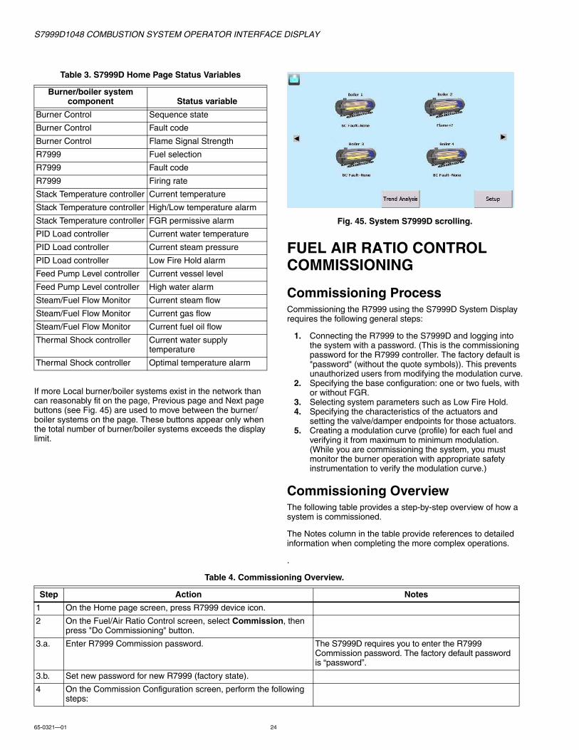
If more Local burner/boiler systems exist in the network than can reasonably fit on the page, Previous page and Next page buttons (see Fig. 45) are used to move between the burner/boiler systems on the page. These buttons appear only when the total number of burner/boiler systems exceeds the display limit.
Fig. 45. System S7999D scrolling.
FUEL AIR RATIO CONTROL COMMISSIONING
Commissioning ProcessCommissioning the R7999 using the S7999D System Display requires the following general steps:
1. Connecting the R7999 to the S7999D and logging into the system with a password. (This is the commissioning password for the R7999 controller. The factory default is "password" (without the quote symbols)). This prevents unauthorized users from modifying the modulation curve.
2. Specifying the base configuration: one or two fuels, with or without FGR.
3. Selecting system parameters such as Low Fire Hold.4. Specifying the characteristics of the actuators and
setting the valve/damper endpoints for those actuators.5. Creating a modulation curve (profile) for each fuel and
verifying it from maximum to minimum modulation. (While you are commissioning the system, you must monitor the burner operation with appropriate safety instrumentation to verify the modulation curve.)
Commissioning OverviewThe following table provides a step-by-step overview of how a system is commissioned.
The Notes column in the table provide references to detailed information when completing the more complex operations.
.
Table 3. S7999D Home Page Status Variables
Burner/boiler system component Status variable
Burner Control Sequence state
Burner Control Fault code
Burner Control Flame Signal Strength
R7999 Fuel selection
R7999 Fault code
R7999 Firing rate
Stack Temperature controller Current temperature
Stack Temperature controller High/Low temperature alarm
Stack Temperature controller FGR permissive alarm
PID Load controller Current water temperature
PID Load controller Current steam pressure
PID Load controller Low Fire Hold alarm
Feed Pump Level controller Current vessel level
Feed Pump Level controller High water alarm
Steam/Fuel Flow Monitor Current steam flow
Steam/Fuel Flow Monitor Current gas flow
Steam/Fuel Flow Monitor Current fuel oil flow
Thermal Shock controller Current water supply temperature
Thermal Shock controller Optimal temperature alarm
Table 4. Commissioning Overview.
Step Action Notes
1 On the Home page screen, press R7999 device icon.
2 On the Fuel/Air Ratio Control screen, select Commission, then press "Do Commissioning" button.
3.a. Enter R7999 Commission password. The S7999D requires you to enter the R7999 Commission password. The factory default password is “password”.
3.b. Set new password for new R7999 (factory state).
4 On the Commission Configuration screen, perform the following steps:

S7999D1048 COMBUSTION SYSTEM OPERATOR INTERFACE DISPLAY
25 65-0321—01
4.a. Select the base configuration. The choices are:
• Unconfigured: selecting this option takes the device back to a factory state and sets the password to “password”.
• Single Fuel• Single Fuel with FGR• Dual Fuel• Dual Fuel with FGR
4.b. Select an actuator to configure: Air, Fuel 1, Fuel 2, or FGR. Actuator buttons corresponding to the base configuration are enabled. Any actuators that have completed configuration (are locked) have a check mark next to the button.
5.a. Select the Direction of Closed Travel: Clockwise or Counterclockwise.
5.b. Select the Actuator’s Valve or Damper Type: Fixed Stops or Continuous Rotation.
5.c. Select the next button.
6.a. Enter the KEY (serial number) of the Actuator. Manually move the actuator to a midspan position to allow the ID unlocking algorithm to function properly. Please ensure all eight digits are entered correctly. You may confirm that an actuator has been successfully brought on-line by noting its flash rate has changed from a rapid flash to a slow flash, i.e. one blink a second.
6.b. Select the OK button.
7.a. Press Auto Seek on Maximum Open Endpoint screen. Only for fixed Stop valve or damper type.
7.b. If necessary, press Open or Close to adjust the actuator position to open Endpoint.
7.c. Press Lock button.
7.d. Select the Next button.
8.a. Press Auto Seek on Maximum Closed Endpoint screen.
8.b. If necessary, press Open or Close to adjust the actuator position to Closed endpoint.
8.c. Press Lock button.
8.d. Select the Next button.
9 Repeat steps 4.b through 8.d to set the configuration of the other actuators in your system.
10 If any System Configuration parameters need to be set, select System Configuration button.
NOTE: Go to System Configuration section for more information.
11.a. Press Next on Commission Configuration screen.
11.b. If a saved profile curve exists and is desired, select Advanced Options button instead of the Next button. See Load Profile Curve section.
Curve is loaded and proceeds to curve commissioning screen.
12 On the Curve Commissioning screen, perform the following steps:
12.a. Switch the external burner demand switch (power LCI terminal 13) and then select the Start Lightoff button.
Wait for actuators to move to preset Air Purge position.
12.b. Press Open and/or Close for Air to move the cursor to the desired Air Purge point of the burner.
The R7999 will automatically move the Air actuator to a 62% open position if it is unconfigured.
12.c. Press Purge button. A “P” will be displayed on the profile.The R7999 will energize its HFP output (terminal 10) which, in turn, allows the burner control to start the purge time. Wait for purge to complete and cursor to move to preset Lightoff position.
Table 4. Commissioning Overview. (Continued)
Step Action Notes
S7999D1048 COMBUSTION SYSTEM OPERATOR INTERFACE DISPLAY
65-0321—01 26
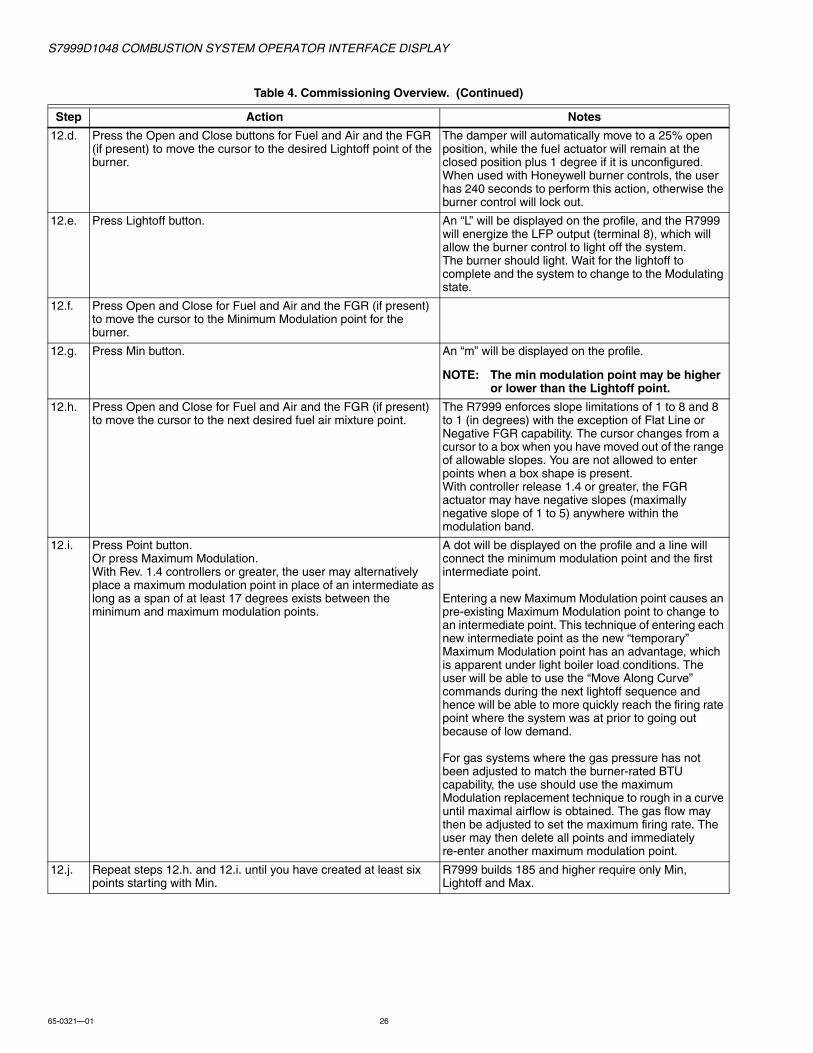
12.d. Press the Open and Close buttons for Fuel and Air and the FGR (if present) to move the cursor to the desired Lightoff point of the burner.
The damper will automatically move to a 25% open position, while the fuel actuator will remain at the closed position plus 1 degree if it is unconfigured.When used with Honeywell burner controls, the user has 240 seconds to perform this action, otherwise the burner control will lock out.
12.e. Press Lightoff button. An “L” will be displayed on the profile, and the R7999 will energize the LFP output (terminal 8), which will allow the burner control to light off the system.The burner should light. Wait for the lightoff to complete and the system to change to the Modulating state.
12.f. Press Open and Close for Fuel and Air and the FGR (if present) to move the cursor to the Minimum Modulation point for the burner.
12.g. Press Min button. An “m” will be displayed on the profile.
NOTE: The min modulation point may be higher or lower than the Lightoff point.
12.h. Press Open and Close for Fuel and Air and the FGR (if present) to move the cursor to the next desired fuel air mixture point.
The R7999 enforces slope limitations of 1 to 8 and 8 to 1 (in degrees) with the exception of Flat Line or Negative FGR capability. The cursor changes from a cursor to a box when you have moved out of the range of allowable slopes. You are not allowed to enter points when a box shape is present.With controller release 1.4 or greater, the FGR actuator may have negative slopes (maximally negative slope of 1 to 5) anywhere within the modulation band.
12.i. Press Point button.Or press Maximum Modulation.With Rev. 1.4 controllers or greater, the user may alternatively place a maximum modulation point in place of an intermediate as long as a span of at least 17 degrees exists between the minimum and maximum modulation points.
A dot will be displayed on the profile and a line will connect the minimum modulation point and the first intermediate point.
Entering a new Maximum Modulation point causes an pre-existing Maximum Modulation point to change to an intermediate point. This technique of entering each new intermediate point as the new “temporary” Maximum Modulation point has an advantage, which is apparent under light boiler load conditions. The user will be able to use the “Move Along Curve” commands during the next lightoff sequence and hence will be able to more quickly reach the firing rate point where the system was at prior to going out because of low demand.
For gas systems where the gas pressure has not been adjusted to match the burner-rated BTU capability, the use should use the maximum Modulation replacement technique to rough in a curve until maximal airflow is obtained. The gas flow may then be adjusted to set the maximum firing rate. The user may then delete all points and immediately re-enter another maximum modulation point.
12.j. Repeat steps 12.h. and 12.i. until you have created at least six points starting with Min.
R7999 builds 185 and higher require only Min, Lightoff and Max.
Table 4. Commissioning Overview. (Continued)
Step Action Notes

S7999D1048 COMBUSTION SYSTEM OPERATOR INTERFACE DISPLAY
27 65-0321—01
Initiate CommissioningBegin commissioning/configuring the ControLinks™ Control device by clicking on the Commissioning button located on the Home page. The Warning screen (Fig. 46) will appear.
You can perform the following actions from this screen:
1. Enter your password to access the commissioning function of the S7999D.
2. Change the password.3. Monitor.
After reading the warning and accepting the responsibility for configuring a safe and efficient fuel/air profile curve, click on the Commission button to exit the Warning screen and display the Commission Password screen.
Commission Warning ScreenThe Commission Warning screen is used to:
• Protect the system from unauthorized users.• Connect the R7999 to the S7999D for commissioning. Refer
to the R7999A,B ControLinks™ controller specification sheet (Form No. 65-0238).
Fig. 46. Commission warning.
12.k. Press Open and Close for Fuel and Air and the FGR (if present) to move the cursor to the Maximum Modulation point for the burner.
For gas systems of which the gas pressure has not been adjusted to match the burner-rated BTU capability, the use should use the maximum Modulation replacement technique to rough in a curve until maximal airflow is obtained. The gas flow may then be adjusted to set the maximum firing rate. The user may then delete all points and immediately re-enter another maximum modulation point. This may save the user some time by not having to successively delete invalid intermediate points due to the gas pressure change.
12.l. Press Max button. An “M” will be displayed on the profile and a line will connect it to the previous intermediate points. The R7999 requires re-verification of any verified curve segments after setting the maximum modulation point.
12.m. Press Prev. Point/Next Point until the cursor reaches the next lower point on the profile. Alternatively the user may add intermediate points as the effective firing rate is lowered. Jump back to 12.h. if the temporary intermediate points were deleted in 12.k.
The line segment turns color, red to green, to indicate the curve has been walked (verified). FGR line segment turns color from brown to cyan.
NOTE: The S7999D requires you to enter at least three points (inclusive of the min and max modulation points) in order to use the “Prev Point” and “Next Point” but-tons.
12.n. Repeat step 12.m. until you have moved along the curve from top to bottom.
The profile is now complete and operational. Status should display “Profile Complete. Ready to Run.”
The R7999 requires reverification of any line segment after the maximum modulation point has been altered.
13.a. If you wish to save the profile you have just created, press Quit button and then the Save button.
The user must insure that the purge point is within the minimum and maximum modulation points before finishing the profile. The purge point can be moved while the burner is firing by simply using the Prev Point, Next Point buttons and pressing the PURGE button at the desired level or at the purge point definition period during the next start up sequence.
13.b. When you are through with the profile, press Quit and then the Finish button.
The Monitor screen appears. You have successfully commissioned the R7999.
Table 4. Commissioning Overview. (Continued)
Step Action Notes

S7999D1048 COMBUSTION SYSTEM OPERATOR INTERFACE DISPLAY
65-0321—01 28
NOTE: Clicking the Home, Back or Monitor button will exit Commissioning mode and display the Home page.
PasswordYou must enter the R7999 Commission password into the system (Fig. 47). The password consists of a minimum of four characters/numbers and a maximum of ten characters/numbers.
Fig. 47. Commission login.
To change the R7999 Commission password, proceed as follows:
1. Select the Set Password button on the Commissioning Warning screen.
2. Enter the current password in the Commission Password field. (The factory default password is “password”.)
3. Press OK. The system must be successfully connected in order to change the password.
4. Enter a new password in the New Password field.5. Press OK.
NOTE: The password is case sensitive. Make sure you write down your new password before you press OK. Once you have pressed this button you cannot enter the system without the password.
Fig. 48. Commissioning login to set password.
Commission ConfigurationThe Commission Configuration screen is used to:
• Identify the configuration of the system you want to commission, for example, dual fuel system with a FGR or a single fuel system, etc.
• Begin configuration of the actuators.• Allow the user to set System Parameters.• Load a curve from the S7999D flash.• Begin configuration of the modulation curve.
This screen (Fig. 49) selects the type (Base Configuration) of ControLinks™ Control System to be configured. The Base Configuration defines the number of actuators connected to the ControLinks™ controller. After the Base Configuration is chosen, the corresponding actuators are enabled as Endpoint Configuration options.
Selecting the Unconfigured Base Configuration sets all the ControLinks™ Control parameters back to the factory default settings. All user configurable data stored in the ControLinks™ Control will be deleted by selecting this option. A warning message is displayed to confirm this selection.
Single Fuel configuration enables the Air and Fuel 1 actuator buttons in the Endpoint Configuration options. Single Fuel with FGR enables the Air, Fuel1 and FGR buttons. Dual Fuel enables the Air, Fuel1 and Fuel2 buttons. Dual Fuel with FGR enables all four actuator buttons. Begin configuring the actuators by selecting the enabled buttons.
S7999D1048 COMBUSTION SYSTEM OPERATOR INTERFACE DISPLAY
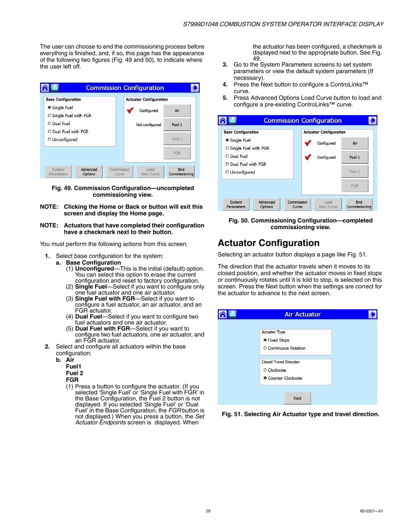
29 65-0321—01
The user can choose to end the commissioning process before everything is finished, and, if so, this page has the appearance of the following two figures (Fig. 49 and 50), to indicate where the user left off.
Fig. 49. Commission Configuration—uncompleted commissioning view.
NOTE: Clicking the Home or Back or button will exit this screen and display the Home page.
NOTE: Actuators that have completed their configuration have a checkmark next to their button.
You must perform the following actions from this screen:
1. Select base configuration for the system:a. Base Configuration
(1) Unconfigured—This is the initial (default) option. You can select this option to erase the current configuration and reset to factory configuration.
(2) Single Fuel—Select if you want to configure only one fuel actuator and one air actuator.
(3) Single Fuel with FGR—Select if you want to configure a fuel actuator, an air actuator, and an FGR actuator.
(4) Dual Fuel—Select if you want to configure two fuel actuators and one air actuator.
(5) Dual Fuel with FGR—Select if you want to configure two fuel actuators, one air actuator, and an FGR actuator.
2. Select and configure all actuators within the base configuration:b. Air
Fuel1Fuel 2FGR(1) Press a button to configure the actuator. (If you
selected ‘Single Fuel’ or ‘Single Fuel with FGR’ in the Base Configuration, the Fuel 2 button is not displayed. If you selected ‘Single Fuel’ or ‘Dual Fuel’ in the Base Configuration, the FGR button is not displayed.) When you press a button, the Set Actuator Endpoints screen is displayed. When
the actuator has been configured, a checkmark is displayed next to the appropriate button. See Fig. 49.
3. Go to the System Parameters screens to set system parameters or view the default system parameters (If necessary).
4. Press the Next button to configure a ControLinks™ curve.
5. Press Advanced Options Load Curve button to load and configure a pre-existing ControLinks™ curve.
Fig. 50. Commissioning Configuration—completed commissioning view.
Actuator ConfigurationSelecting an actuator button displays a page like Fig. 51.
The direction that the actuator travels when it moves to its closed position, and whether the actuator moves in fixed stops or continuously rotates until it is told to stop, is selected on this screen. Press the Next button when the settings are correct for the actuator to advance to the next screen.
Fig. 51. Selecting Air Actuator type and travel direction.

S7999D1048 COMBUSTION SYSTEM OPERATOR INTERFACE DISPLAY
65-0321—01 30
Actuator Serial NumberThis page (Fig. 52) allows the user to enter the serial number to unlock and configure the corresponding actuator.
Fig. 52. Entering Air Actuator serial number.
Fig. 53. Air Actuator endpoint reset.
The user must enter the 8-digit serial number into the Serial Number field and press the OK button to proceed.
The Backspace button allows the user to erase the last digit entered into the Serial Number field.
The Clear button erases the entire Serial Number field and forces the user to enter eight new digits.
If the serial number has been entered for the actuator earlier (revisiting the actuator configuration), the current serial number displays. If the OK button is selected at this point, a popup similar to Fig. 53 displays. Answering Yes causes the actuator endpoints to be cleared, requiring the open and closed endpoints to be reset.
NOTE: You must resend the KEY (serial number) any time you revise the closed direction setting or change the type of end-stop selection.
Actuator EndpointsSet the endpoints as shown (see Fig. 54 and 55).
How To Set the Actuator Maximum Open/Closed PositionsTo set the maximum open and closed positions for the actuator, proceed as follows:
1. From the Commission Configuration screen, select the actuator button that needs changing.
NOTE: Buttons are disabled when system is fully commissioned and LCO is on.
2. Closed Travel Direction and Actuator Type screen is dis-played. If no changes are needed, select the Next button.
3. Serial Number screen is displayed. If correct serial number is displayed, select the OK button. You will be asked if you want to reset the Open and Closed endpoints in a pop-up screen. Select Yes to reset both of them or No if you want to keep the current settings.
4. Set Maximum Open Position screen displays. If Open position has been previously set, you must select Unlock Position button to allow it to be changed. Press Auto Seek and the controller automatically opens (or closes) the actuator to its maximum open (or closed) value.
NOTE: This button is only enabled for actuator types that are fixed stop actuators.
5. When the actuator has been driven to is maximum position, visually verify its position and use the Open or Close buttons to manually adjust the maximum position if necessary. Press the Lock Position button for the endpoint once the appropriate position has been achieved and verified.
6. Repeat Steps 4 and 5 for the Closed position.7. Press the Next button. This will return you to the
Commission Configuration screen to configure another actuator. After all actuators are configured, press the Next button again to display the Commission Curve screen.
Fig. 54. Set Actuator Max Open Endpoint.

S7999D1048 COMBUSTION SYSTEM OPERATOR INTERFACE DISPLAY
31 65-0321—01
Fig. 55. Set Actuator Max Close Endpoint.
Curve CommissioningThe Commission Curve screen for Fuel 1 or Fuel 2 is used to:
• Enter points on the graph to indicate the Air Purge position, Lightoff position, Maximum and Minimum modulation positions, and intermediate positions for the actuators for the specified fuel (Fuel 1 or Fuel 2).
• Create a curve that provides safe and efficient operation of the burner from minimum to maximum modulation.
• Verify the profile that was created.• Save the profile you created to a default curve if desired.The following buttons are displayed on the screen:
1. Fuel/Air/FGR: • Open/Close—Press one of these buttons to manually
open or close the actuator the number of degrees indicated in the drop-down box (from 0.1 to 10). When you are positioning actuators, while any actuators are below 20%, you can only move the actuator 3 degrees at a time. This is a safety constraint.
2. Point Type Buttons:• After positioning the actuator(s), press the
appropriate button to save the point on the graph. a. Point—Press to save positions on the curve that are
between the max and min modulation points. A point is displayed on the graph each time you press this button. You need at least 5 intermediate points
between the max and min modulation points on a curve for a valid profile, except for builds 185 and higher.
b. Lightoff—Press to save the lightoff position on the graph. An ‘L’ is displayed on the graph to indicate the lightoff point. Only one lightoff point is allowed per curve.
c. Max—Press to save the maximum modulation position on the graph. An ‘M’ is displayed on the graph to indicate the maximum modulation point. Only one maximum modulation point is allowed per curve.
d. Min—Press to save the minimum modulation position on the graph. An ‘m’ is displayed in the graph to indicate the minimum modulation point. Only one minimum modulation point is allowed per curve.
e. Purge—Press to save the air purge position on the graph. A ‘P’ is displayed on the graph to indicate the air purge point. Only one air purge point is allowed per curve.
3. Delete:a. Delete Position—Press to delete a point on the
curve. To delete the point, you must position the cur-sor on the point.
b. Delete All Positions—Press to delete ALL positions on the curve, including the lightoff, air purge, max and min modulation points. Use this button ONLY when you want to start creating the curve from the beginning.
4. Start Lightoff/Stop Modulation:• This button serves a dual purpose. Pressing this
button activates the burner controller lightoff sequence. If the lightoff sequence is successful, this button then displays Stop Modulation. If the lightoff sequence fails, the Status window indicates the problem.
• If you want to stop the system at any time during the commissioning process, use the Stop Modulation button.
5. Previous Point/Next Point• Press these buttons to move the actuators along the
curve to a previously set position. Use these buttons to reposition the cursor or to ‘walk the curve’ and verify system operation. As the curve is verified, the color of the curve changes.
• Curve segments will be displayed in red when not validated. You must ‘walk the curve’ to verify system operation with the curve.
NOTE: The S7999D requires you to enter at least 3 points (inclusive of the min and max modulation points) to use the “Move Along the Curve” but-tons.

S7999D1048 COMBUSTION SYSTEM OPERATOR INTERFACE DISPLAY
65-0321—01 32
6. Quit• Press this button when done with the curve at this
point. The following buttons display:a. Back:
• Press to return to the Commission Configuration screen.
b. Home:• Go to Home page.
c. Finish:• Press to save the profile you have created. The
Finish button is grayed out until you complete the profile. After you press this button, the Monitor screen is displayed. You can exit the program from there.
d. Save:• Save Curve S7999D flash (Fig. 60 and 61). Control
returns to Curve Commission screen.
e. Cancel:• Cancel Quit and continue curve configuration.
The following screens depict the options possible to create or change the profile curve for the currently selected fuel. The operation of this screen is explained in the Commission Curve screen, defined earlier.
Curve commissioning can only occur after all actuators have been completely configured and locked. The Next button on the Commission Configuration screen is not enabled until this is true. Once the actuators are configured, the Next button brings the user to the Curve Commissioning screen.
NOTE: The Load Curve button also brings the user to this screen. It is also only enabled after the actuators have been configured.
Fig. 56. Start lightoff.
Fig. 57. Purge setting on Commission.
Fig. 58. Commissioning—set lightoff.
Fig. 59. Commissioning curve—Delete points.

S7999D1048 COMBUSTION SYSTEM OPERATOR INTERFACE DISPLAY
33 65-0321—01
Fig. 60. Completed Commissioning Curve.
Fig. 61. Commissioning—save curve to display.
Fig. 62. Save curve, enter name.
Fig. 63. Quit Commissioning Finish.
System ParametersNOTE: All System Parameter pages are disabled until all
actuators are configured.
1. Press the System Configuration button on the Commission Configuration screen to set system parameters. System parameters let you choose advanced features that use the auxiliary 4-20mA input such as: low fire hold and/or FGR holds, configure actuator positions during standby, configure the position of the non-selected fuel actuator, configure action of the FGR actuator during purge, adjust the postpurge timing parameter, and select a maximum firing rate limit via the manual potentiometer input.
2. Setting these parameters is optional. If you do not set system parameters, the default values will be used. See Default System Parameters for the default value/setting for each parameter.
NOTE: The selection of Xma (auxiliary mA) operation system parameters result in a common attribute between the operation of both fuel selections. For example, selecting low fire hold will apply to both fuels.
a. Home—Press to go to Home page.b. Back—Press to return to the previous screen.c. Next—Press to move to the next screen for
additional system parameters. d. Save Setting—Save the settings shown on the cur-
rent page.e. End System Configuration—Press when finished
setting system parameters. Returns to Commission Configuration screen.
If you make changes to the system parameters on the screen, they are not saved until you press the Save Setting button.
System parameters you can set include:
• Stack or boiler water temperature sensor operating parameters.
• Controller timing (postpurge time).• Auto/manual maximum firing rate option via the manual
potentiometer input.• Program standby positions and nonselected fuel position.• FGR behavior during purge.• XmA Operation (Auxiliary mA input).
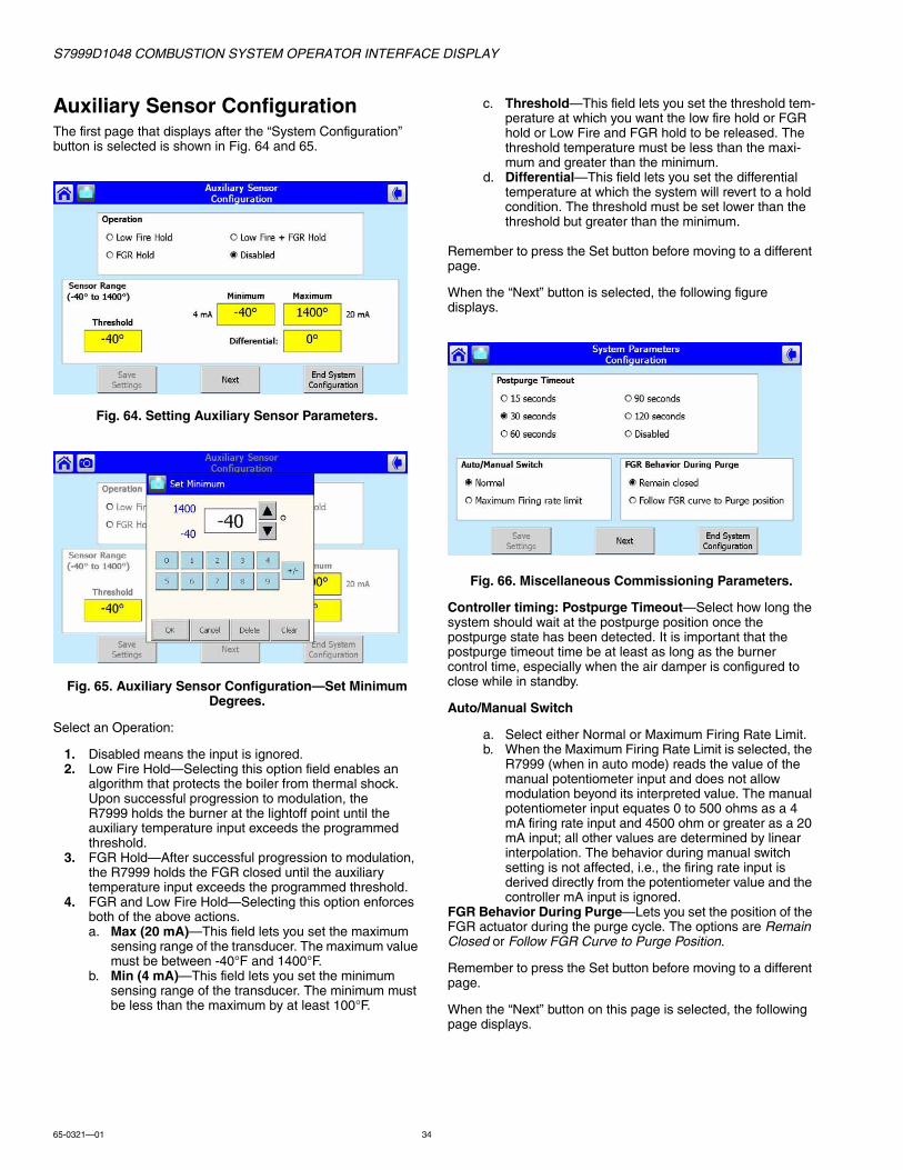
S7999D1048 COMBUSTION SYSTEM OPERATOR INTERFACE DISPLAY
65-0321—01 34
Auxiliary Sensor ConfigurationThe first page that displays after the “System Configuration” button is selected is shown in Fig. 64 and 65.
Fig. 64. Setting Auxiliary Sensor Parameters.
Fig. 65. Auxiliary Sensor Configuration—Set Minimum Degrees.
Select an Operation:
1. Disabled means the input is ignored.2. Low Fire Hold—Selecting this option field enables an
algorithm that protects the boiler from thermal shock. Upon successful progression to modulation, the R7999 holds the burner at the lightoff point until the auxiliary temperature input exceeds the programmed threshold.
3. FGR Hold—After successful progression to modulation, the R7999 holds the FGR closed until the auxiliary temperature input exceeds the programmed threshold.
4. FGR and Low Fire Hold—Selecting this option enforces both of the above actions.a. Max (20 mA)—This field lets you set the maximum
sensing range of the transducer. The maximum value must be between -40°F and 1400°F.
b. Min (4 mA)—This field lets you set the minimum sensing range of the transducer. The minimum must be less than the maximum by at least 100°F.
c. Threshold—This field lets you set the threshold tem-perature at which you want the low fire hold or FGR hold or Low Fire and FGR hold to be released. The threshold temperature must be less than the maxi-mum and greater than the minimum.
d. Differential—This field lets you set the differential temperature at which the system will revert to a hold condition. The threshold must be set lower than the threshold but greater than the minimum.
Remember to press the Set button before moving to a different page.
When the “Next” button is selected, the following figure displays.
Fig. 66. Miscellaneous Commissioning Parameters.
Controller timing: Postpurge Timeout—Select how long the system should wait at the postpurge position once the postpurge state has been detected. It is important that the postpurge timeout time be at least as long as the burner control time, especially when the air damper is configured to close while in standby.
Auto/Manual Switch
a. Select either Normal or Maximum Firing Rate Limit.b. When the Maximum Firing Rate Limit is selected, the
R7999 (when in auto mode) reads the value of the manual potentiometer input and does not allow modulation beyond its interpreted value. The manual potentiometer input equates 0 to 500 ohms as a 4 mA firing rate input and 4500 ohm or greater as a 20 mA input; all other values are determined by linear interpolation. The behavior during manual switch setting is not affected, i.e., the firing rate input is derived directly from the potentiometer value and the controller mA input is ignored.
FGR Behavior During Purge—Lets you set the position of the FGR actuator during the purge cycle. The options are Remain Closed or Follow FGR Curve to Purge Position.
Remember to press the Set button before moving to a different page.
When the “Next” button on this page is selected, the following page displays.

S7999D1048 COMBUSTION SYSTEM OPERATOR INTERFACE DISPLAY
35 65-0321—01
Actuator Standby Positions (Presets)
Fig. 67. Fuel Standby Positions Preset.
Program Standby Position—Lets you set the position of the actuators when the controller is in the standby position. For each actuator, select Closed, Lightoff or Open. If you select Open, you must enter a value in the appropriate field to indicate how wide the actuator should be opened (percentage of the actuator span value).
Program Non Selected Fuel Position—Lets you set the position of the fuel actuator of the fuel that is not currently being used. Select Closed, Lightoff or Open.
Remember to press the Set button before moving to a different page.
Fig. 68. Fuel Standby Positions—Set Standby Open Percentage.
Default System ParametersThe default values/settings for each system parameter are shown in Table 5.
Advanced Options Some advanced commissioning options are available by selecting the “Advanced Options” button on the Commissioning Configuration page (Fig. 69).
Fig. 69. Advanced Options.
Factory DefaultTo reset the Fuel/Air Ratio Control to factory default, select the “Factory Default” button. A confirmation pop-up box displays (Fig. 70) before the reset occurs. The user selects the “Yes” button to continue with the reset. This feature is only enabled for R7999 controllers that are build 180 and newer.
Table 5. Default Values/Settings for System Parameters
Parameter Default
Xma Operation
Operation Disabled
Max (20 mA) NA
Min (4 mA) NA
Threshold NA
Differential NA
Controller Timing
Postpurge time 30 seconds
Automanual Switch
Automanual Switch Normal Mode
Program Standby Position
Fuel Selection 1
Fuel Closed
Air Closed
FGR Closed
Fuel Selection 2
Fuel Closed
Air Closed
FGR Closed
Program Non-Selected Fuel Position
Fuel Selection 1
Fuel Selection 2 Closed
Fuel Selection 2
Fuel Selection 1 Closed
FGR Behavior During Purge
FGR Behavior During Purge Remains Closed.
Table 5. Default Values/Settings for System Parameters
Parameter Default

S7999D1048 COMBUSTION SYSTEM OPERATOR INTERFACE DISPLAY
65-0321—01 36
Fig. 70. Advanced Options—Reset Factory Defaults.
Fuel/Air Ratio Control EEPROM MaintenanceData in the Fuel/Air Ratio Control internal and external EEPROMs can be saved to non-volatile (flash) storage in the S7999D. This data includes the commissioning settings and other run-time information used by the R7999.The EEPROM image data can be stored in the S7999D (downloaded) and restored later (uploaded) back into the same R7999 or a replacement. EEPROM images for only one R7999 can be saved in the S7999D.
When no EEPROM images are stored in the S7999D, the following figure displays (Fig. 71).
Internal EEPROM contains hysteresis, control accuracy and other factory settings. External EEPROM contains actuator settings, curve data and other settings made by the user during commissioning of the R7999.
Fig. 71. EEPROM Maintenance—No image.
If EEPROM images exist, the name assigned to the images, the R7999 build associated with the images, the date and time that the backup images were created, and the sizes of the images are displayed on the screen (Fig. 72).
Fig. 72. EEPROM Maintenance—Images exist.

S7999D1048 COMBUSTION SYSTEM OPERATOR INTERFACE DISPLAY
37 65-0321—01
If the EEPROM images don’t match with the R7999 build, an error is displayed and no uploading is permitted.
To download the R7999 EEPROM data to the S7999D, the “Download EEPROM” image button is selected. The user is asked to confirm that this action should proceed.
When the user chooses to continue with the download, the user is asked to enter an image name to associate with the EEPROM data. After the name is entered, the “OK” button is selected. To abort the download, the “Cancel” button is selected.
The download takes less than a minute to execute. The user should wait until the download is complete before touching the screen.
The user can choose to upload the internal EEPROM only, the external EEPROM only, or both EEPROM images. In any case, the user is asked to confirm this action (Fig. 73) before proceeding.
Fig. 73. EEPROM Maintenance—EEPROM Write.

S7999D1048 COMBUSTION SYSTEM OPERATOR INTERFACE DISPLAY
65-0321—01 38
If the user chooses to remove the EEPROM image data from the S7999D flash, the user selects the “Delete EEPROMs” images button. The user is asked to confirm this action (Fig. 74) before proceeding.
Fig. 74. EEPROM Maintenance—Delete Images from S7999D.
Load Profile CurveA profile modulation curve stored in the S7999D can be loaded for use as the active curve for commissioning. When the user selects the “Load Profile Curve” button, the following screen (Fig. 75) displays.
Fig. 75. Load Profile Curve.
A list of all defined profile curves is given. The user selects which one to load and presses the “OK” button to load it. A view of the curve can be seen before loading by pressing the “View” button.
MONITORINGThe Honeywell devices attached to the burner system are represented by icon buttons on the Home page. To obtain status information about each device, the user selects the button that corresponds to the device. A new page displays with status information exclusively about that device.
If any device is currently in a fault condition, the device icon is displayed with a red color. Also, if audio alarm is enabled for fault conditions (see User Preferences), an audio alarm sounds while the fault continues to exist. To turn off the audio alarm, the user must go to the device status page to view the fault history or press the Alarm Silence icon on the Home page.
Burner Control (7800 SERIES)Monitoring the 7800 SERIES burner control is performed by clicking on the Burner Control icon on the Home Screen. Status information similar to that displayed in Fig. 76 appears.
NOTE: Pressing the Home or Back buttons in the upper corners of the screen will exit the status screen and return to the Home page.
Fig. 76. Burner Control Status.

S7999D1048 COMBUSTION SYSTEM OPERATOR INTERFACE DISPLAY
39 65-0321—01
If the burner control is currently in a lockout condition, the lockout cause is displayed on the screen (Fig. 77). The lockout fault is also visible in the fault history. If audio alarm is enabled for fault conditions (see “Setting up the S7999D display” on page 15), then an audio alarm sounds when the lockout occurs. To turn off the audio alarm, the user touches the "OK" button in the Fault pop-up dialog box or the "Alarm Bell" icon displayed in the lower left corner of the Home page.
Fig. 77. Burner Control Status—Lockout.
The “Diagnostic Info” button displays the terminal and jumper states of the burner control (Fig. 78).
Fig. 78. Burner Control—Diagnostic Information.
The “Remote Reset” button allows the user to remotely reset the burner control (Fig. 81). Extreme care should be exercised before proceeding with the reset (Disabled for S7810M1029).
The user must log in with a valid S7999D System password before performing a remote reset (Fig. 79 and 80).
Fig. 79. Burner Control—Enter Password.
Fig. 80. Burner Control—Password Login.
Finally, confirm that the Burner Control is to be remotely reset.
Fig. 81. Burner Control—Remote Reset.

S7999D1048 COMBUSTION SYSTEM OPERATOR INTERFACE DISPLAY
65-0321—01 40
The “Show Faults” button displays the burner control fault history (Fig. 82). This button has a red color when the burner control is currently in a fault (lockout) condition.
Fig. 82. Burner Control—Fault History, left view.
NOTE: Fault timestamps are cleared after the S7999D resets or when switching to a different burner system.
Fig. 83. Burner Control—Fault History, right view.
S7830 Expanded AnnunciatorMonitoring the S7830 Expanded Annunciator is performed by clicking on the Expanded Annunciator icon on the Home page.
The expanded annunciator has 19 different terminals indicating separate conditions (see Fig. 84). A colored LED located to the left of the terminal indicates whether the terminal state (and condition) is on (green) or off (gray). Current State is the status of the burner equipment control, limit and interlocks.
Fig. 84. Expanded Annunciator Status.
NOTE: Pressing the Home or Back button in the upper corners of the screen will exit the status screen and return to the Home page.
ControLinks™ Fuel/Air Ratio Control (R7999)Monitoring the ControLinks™ Fuel/Air Ratio Control system is performed by clicking on the Fuel/Air Control icon located on the Home page to display the current configuration status, actuator positions and terminal states:
1. Fuel:• Displays the current position of the fuel actuator.
2. Air:• Displays the current position of the air actuator.
3. FGR:• Displays the current position of the FGR actuator (if
present).4. Firing Rate:
• Displays the current firing rate position (in milliamps).5. Aux Temperature Input:
• Displays the actual interpreted temperature reading from the auxiliary input. If the function is disabled, the value indicates “disabled.”
6. Status:• Indicates system status, for example, manual
modulation, air purge, lightoff sequence, etc.7. Cycle:
• Indicates the current cycle of the system, with one being the first call-for-heat cycle since the system was commissioned.
8. Active Alarm:• Indicates if the system is in an Alarm state.
9. Alarm History (use Show Faults buttons):• Displays all alarms that have been generated. The
dropdown box displays the cycle the alarm occurred in and the alarm type.
10. Inputs/Outputs:• All Outputs and Inputs are displayed and their current
state is noted. See R7999 Outputs and Inputs on page 58 for a description.
11. Back/Home:• Go to Home page.

S7999D1048 COMBUSTION SYSTEM OPERATOR INTERFACE DISPLAY
41 65-0321—01
Fig. 85. Fuel/Air Ratio Control Status.
The Fuel/Air Ratio Control faults history can be viewed by selecting the “Show Faults” button (Fig. 86). This button has a red color when the Fuel/Air Ratio Control is currently in a fault condition. If audio alarm is enabled for fault conditions (see “Setting up the S7999D display” on page 15), then an audio alarm also sounds when the fault occurs. The audio alarm continues to sound until either the fault is cleared (e.g., R7999 is reset), the fault history is viewed, the "OK" button is touched in the Fault pop-up dialog box, or the "Alarm Bell" icon is touched on the Home page.
Fig. 86. Fuel/Air Ratio Control—Fault History, left view.
NOTE: Timestamping Values are cleared after the S7999D resets, or when switching to a different burner system or from/to the local Fuel/Air Con-trol.
Fig. 87. Fuel/Air Ratio Control—Fault History, right view.
Fuel/Air Ratio Control ConfigurationCommission configuration selections and diagnostic information about the Fuel/Air Ratio Control can be viewed by selecting the “View Configuration” button on the Fuel/Air Ratio Control page. A configuration page like the one in Fig. 88 displays to show this information.
Fig. 88. Fuel/Air Ratio Control Configuration.Running Modulation Time is an accumulative time of how long the Fuel/Air Ratio Control has been in a modulated state, i.e., when it has been controlling the actuators in an active run state following a successful lightoff. This running time accumulates over each cycle of the Fuel/Air Ratio Control and will stop when the Fuel/Air Ratio Control is not in a modulate state.
The “Auxiliary Sensor” button displays configuration settings made for the auxiliary sensor input to the Fuel/Air Ratio Control. It also displays the current reading of the auxiliary sensor. An Auxiliary Sensor must first be connected to the Fuel Air Ratio controller to use this function.
The “Presets” button displays the actuator preset settings for the currently selected fuel (Fig. 89). Presets are actuator positions used for the three indicated states on the left side of the screen.

S7999D1048 COMBUSTION SYSTEM OPERATOR INTERFACE DISPLAY
65-0321—01 42
Fig. 89. Fuel Preset Settings.The “Diagnostics” button displays diagnostic information about the Fuel/Air Ratio Control (Fig. 90). Current hysteresis value can be viewed or changed by selecting the “Hysteresis” button. See the Set Hysteresis section for more information regarding this button selection.
Fig. 90. Fuel/Air Ratio Control Diagnostics.The “Show Faults” button displays the Fuel/Air Ratio Control fault history (Fig. 91 and Fig. 92) in the same manner that it does on the Fuel/Air Ratio Control status page. This button provides another place to display these faults.
Fig. 91. Fuel/Air Ratio Control Fault History, left view.
Fig. 92. Fuel/Air Ratio Control Fault History, right view.
Set HysteresisThis feature is available for all ControLinks™ Fuel/Air Ratio Control software builds except 127, 140 and 176 (see Fuel/Air Control Configuration screen for build number). The Fuel/Air Ratio Control must be updated to use this feature. This feature is also only available for the Fuel/Air Ratio Control attached to a S7999D COM port that has been configured for "Fuel/Air Ratio Control only (Commission)”.
The hysteresis value controls the amount of hysteresis for the 4 to 20 mA firing rate (CmA) input signal. Adjusting the hysteresis value determines when the R7999 reacts to a firing rate change in the opposite direction. The R7999 only reacts to a firing rate change in the opposite direction when it has increased/decreased more than the user-selected hysteresis value. However, the R7999 always follows the firing rate signal as it changes in the same direction.
For example: When a hysteresis value of 0.5 mA has been selected and the firing rate drops from 12 mA to 10 mA, the R7999 will not begin to follow an increased firing rate until it increases to a value of 10.5 mA or higher. All firing rate values between 10 mA and 10.5 mA are interpreted as a value of 10 mA. The configured actuators remain at their corresponding 10 mA firing rate position until a new firing rate is accepted.
Increasing the hysteresis value may reduce the amount of actuator dither/hunting and premature wear-out due to a noisy environment or an intelligent firing rate controller continuously attempting to satisfy a very precise setpoint.
Use the left/right adjust bar on the Hysteresis screen for large changes to the hysteresis value (Fig. 93). Use the up/down buttons on the bottom of the screen to slowly fine-tune the desired hysteresis selection. Pressing the “Set Hysteresis” button will cause the R7999 to reset and the new value will be written into nonvolatile memory.
The user is asked to confirm setting the hysteresis to the new value (Fig. 94). The “Reset to Current” button causes the current value to be copied to the proposed new value field, similar to an undo operation. See Fig. 93 and 94.

S7999D1048 COMBUSTION SYSTEM OPERATOR INTERFACE DISPLAY
43 65-0321—01
Fig. 93. Set Hysteresis.
Fig. 94. Confirm setting—Hysteresis.
ActuatorThe status of each actuator can be viewed by clicking on the icon on the Home page corresponding to that actuator. A screen similar to that in Fig. 95 is displayed.
Fig. 95. Actuator Status.
For Modbus™ burner systems (when the Fuel/Air Control is connected to the S7810M Modbus Module), some of this information is not available: Key, Stop Type, Close Direction, and State. This information is blank on the screen in this case.
When the Fuel/Air Ratio Control system is connected to a S7999D Com port that has been configured for Fuel/Air Ratio only (Commission), the State status indicates whether the actuator has been configured (key, stop type, and close direction has been set) or not by displaying “CONFIGURED” for its state. If the actuator has been configured and also has its endpoints locked, the state displays a “LOCKED” status.
Actuator fault history can be viewed by selecting the “Show Faults” button (Fig. 96 and Fig. 97).
Fig. 96. Actuator Fault History, left view.
Fig. 97. Actuator Fault History, right view.
Diagnostic information about the actuator can be viewed by selecting the “Diagnostics” button. Diagnostic data for all actuators is displayed at the same time to give a quick snapshot of all actuator activity. The data can be displayed in degrees (Fig. 98) or in analog-to-digital counts (Fig. 99).

S7999D1048 COMBUSTION SYSTEM OPERATOR INTERFACE DISPLAY
65-0321—01 44
Fig. 98. Actuator Diagnostics—in degrees.
Fig. 99. Actuator Diagnostics—in A/D counts.
The button on the bottom of the screen toggles the user between the formats to display the data in.
Set Control AccuracyThe “Control Accuracy” button, if enabled, allows the user to view the current control accuracy setting and change it, if desired.
This feature is only available for Fuel/Air Control software builds higher than 178. The Fuel/Air Control must be updated to use this feature. The “Control Accuracy” button on the Actuator screen is grayed-out when the Fuel/Air Control software build is 178 or below (see Fuel/Air Ratio Control Configuration page for build number).
The control accuracy setting controls how closely the actuators follow the profile curve configured in a Fuel/Air Control and defines the allowable tolerance for achieving each commanded position. The R7999 system normally drives the actuators to within 0.1 degree (default value) of the programmed curve, but many applications may not require this type of accuracy. Increasing the control accuracy value may reduce the amount of actuator dither/hunting and premature wearout due to a noisy environment or a potentiometer.
When the “Control Accuracy” button is selected, a new page (Fig. 100) is displayed. Pressing the Set Accuracy button causes the Fuel/Air Control to reset and store the user-selected value in the Fuel/Air Control nonvolatile memory.
NOTE: Setting the control accuracy to a value other than 0.1 degree disables the 0.1 degree positioning command option when commissioning the curve. This setting applies to all actuators, not just the actuator that has its status displayed.
Fig. 100. Set Control Accuracy.
The user is asked to confirm setting the control accuracy to a new value (Fig. 101). The Fuel/Air Ratio Control is reset during this setting change.
Fig. 101. Confirm Setting—Control Accuracy.
UDC CONTROLLERSUDC controllers must be manually assigned to their appropriate burner/boiler system. This assignment is done on the UDC Controllers page (Fig. 102). This setup page is reached from the “UDC Controller” button on the Control Setup page (see “Setting up the S7999D display” on page 15).
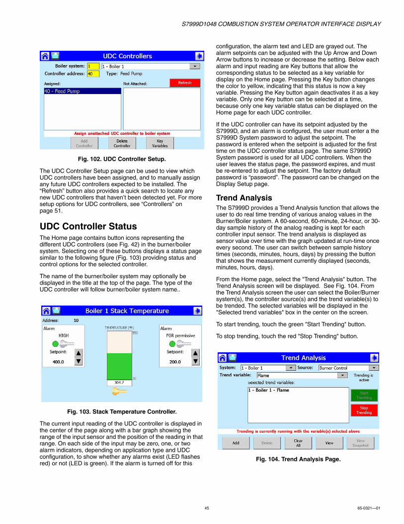
S7999D1048 COMBUSTION SYSTEM OPERATOR INTERFACE DISPLAY
45 65-0321—01
Fig. 102. UDC Controller Setup.
The UDC Controller Setup page can be used to view which UDC controllers have been assigned, and to manually assign any future UDC controllers expected to be installed. The “Refresh” button also provides a quick search to locate any new UDC controllers that haven’t been detected yet. For more setup options for UDC controllers, see “Controllers” on page 51.
UDC Controller StatusThe Home page contains button icons representing the different UDC controllers (see Fig. 42) in the burner/boiler system. Selecting one of these buttons displays a status page similar to the following figure (Fig. 103) providing status and control options for the selected controller.
The name of the burner/boiler system may optionally be displayed in the title at the top of the page. The type of the UDC controller will follow burner/boiler system name..
Fig. 103. Stack Temperature Controller.
The current input reading of the UDC controller is displayed in the center of the page along with a bar graph showing the range of the input sensor and the position of the reading in that range. On each side of the input may be zero, one, or two alarm indicators, depending on application type and UDC configuration, to show whether any alarms exist (LED flashes red) or not (LED is green). If the alarm is turned off for this
configuration, the alarm text and LED are grayed out. The alarm setpoints can be adjusted with the Up Arrow and Down Arrow buttons to increase or decrease the setting. Below each alarm and input reading are Key buttons that allow the corresponding status to be selected as a key variable for display on the Home page. Pressing the Key button changes the color to yellow, indicating that this status is now a key variable. Pressing the Key button again deactivates it as a key variable. Only one Key button can be selected at a time, because only one key variable status can be displayed on the Home page for each UDC controller.
If the UDC controller can have its setpoint adjusted by the S7999D, and an alarm is configured, the user must enter a the S7999D System password to adjust the setpoint. The password is entered when the setpoint is adjusted for the first time on the UDC controller status page. The same S7999D System password is used for all UDC controllers. When the user leaves the status page, the password expires, and must be re-entered to adjust the setpoint. The factory default password is “password”. The password can be changed on the Display Setup page.
Trend AnalysisThe S7999D provides a Trend Analysis function that allows the user to do real time trending of various analog values in the Burner/Boiler system. A 60-second, 60-minute, 24-hour, or 30-day sample history of the analog reading is kept for each controller input sensor. The trend analysis is displayed as sensor value over time with the graph updated at run-time once every second. The user can switch between sample history times (seconds, minutes, hours, days) by pressing the button that shows the measurement currently displayed (seconds, minutes, hours, days).
From the Home page, select the "Trend Analysis" button. The Trend Analysis screen will be displayed. See Fig. 104. From the Trend Analysis screen the user can select the Boiler/Burner system(s), the controller source(s) and the trend variable(s) to be trended. The selected variables will be displayed in the "Selected trend variables" box in the center on the screen.
To start trending, touch the green "Start Trending" button.
To stop trending, touch the red "Stop Trending" button.
Fig. 104. Trend Analysis Page.
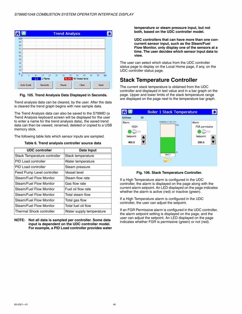
S7999D1048 COMBUSTION SYSTEM OPERATOR INTERFACE DISPLAY
65-0321—01 46
Fig. 105. Trend Analysis Data Displayed in Seconds.
Trend analysis data can be cleared, by the user. After the data is cleared the trend graph begins with new sample data.
The Trend Analysis data can also be saved to the S7999D (a Trend Analysis keyboard screen will be displayed for the user to enter a name for the trend analysis data), the saved trend data can then be viewed, renamed, deleted or copied to a USB memory stick.
The following table lists which sensor inputs are sampled.
NOTE: Not all data is sampled per controller. Some data input is dependent on the UDC controller model. For example, a PID Load controller provides water
temperature or steam pressure input, but not both, based on the UDC controller model.
UDC controllers that can have more than one con-current sensor input, such as the Steam/Fuel Flow Monitor, only display one of the sensors at a time. The user decides which sensor input data to view.
The user can select which status from the UDC controller status page to display on the Local Home page, if any, on the UDC controller status page.
Stack Temperature ControllerThe current stack temperature is obtained from the UDC controller and displayed in text value and in a bar graph on the page. Upper and lower limits of the stack temperature range are displayed on the page next to the temperature bar graph.
Fig. 106. Stack Temperature Controller.
If a High Temperature alarm is configured in the UDC controller, the alarm is displayed on the page along with the current alarm setpoint. An LED displayed on the page indicates whether the alarm is active (red) or inactive (green).
If a High Temperature alarm is configured in the UDC controller, the user can adjust the setpoint.
If an FGR Permissive alarm is configured in the UDC controller, the alarm setpoint setting is displayed on the page, and the user can adjust the setpoint. An LED displayed on the page indicates whether FGR is permissive (green) or not (red).
Table 6. Trend analysis controller source data
UDC controller Data Input
Stack Temperature controller Stack temperature
PID Load controller Water temperature
PID Load controller Steam pressure
Feed Pump Level controller Vessel level
Steam/Fuel Flow Monitor Steam flow rate
Steam/Fuel Flow Monitor Gas flow rate
Steam/Fuel Flow Monitor Fuel oil flow rate
Steam/Fuel Flow Monitor Total steam flow
Steam/Fuel Flow Monitor Total gas flow
Steam/Fuel Flow Monitor Total fuel oil flow
Thermal Shock controller Water supply temperature

S7999D1048 COMBUSTION SYSTEM OPERATOR INTERFACE DISPLAY
47 65-0321—01
PID Load ControllerCurrent load water temperature or steam pressure is obtained from the UDC controller and displayed in text value and in a bar graph on the page (see Fig. 107 and 108). Upper and lower limits of the water temperature/steam pressure range are displayed on the page next to the load bar graph.
Fig. 107. Steam PID Load Controller.
Fig. 108. Water Temperature Load Controller.
The control setpoint for PID modulation is obtained from UDC controller and displayed on the page. The control setpoint can also be adjusted on this page. The control setpoint is set by the user using the Up Arrow and Down Arrow buttons. The UDC controller modulates the burner control toward this target setpoint.
Status of the On-Off relay is obtained from the UDC controller. An LED displayed on the page indicates when demand is on (green) or off (red).
If a Low Fire Hold alarm is configured in the UDC controller, the setpoint of this alarm is obtained from the UDC controller and displayed on the page. The status of the alarm is displayed on the page with an LED that is red when Low Fire Hold has occurred and green when the system isn’t in Low Fire Hold.
The user can adjust the alarm setpoint of both alarms. Manual control of the UDC controller output is also permitted by selecting the yellow “Auto Output” button. Adjustment is raised or lowered in 1% (0.16 mA) increments. The S7999D System password (same as Setpoint Adjustment) is required before manual control is permitted. After successful login, the Up Arrow and Down Arrow buttons can be used to change the alarm setpoints.
PID modulation output is obtained from UDC controller and displayed on the page in text value (mA).
Feed Pump Level ControllerThe current water supply level (percent full) is obtained from the UDC controller and displayed both in text value and in a bar graph on the page. Upper (100%) and lower (0%) limits are displayed next to the bar graph.
Fig. 109. Feed Pump Level Controller.
Status of the Start-Stop relay in the UDC controller is displayed on the page as an LED that is green when the relay is in Start mode and red when the relay is in Stop mode. The Start Pump and Stop Pump setpoints (in percent) are obtained from the UDC controller and displayed on the page. The user can adjust these Start Pump and Stop Pump setpoints with the Up Arrow and Down Arrow buttons. Successful password login is required before the setpoints can be adjusted.
If a High Water alarm is configured in the UDC controller, the setpoint of this alarm is displayed on the page. The status of the alarm is indicated by an LED that is red when a status and high water condition exists, and green when safe water level exists. The user can adjust the alarm setpoint on the page.

S7999D1048 COMBUSTION SYSTEM OPERATOR INTERFACE DISPLAY
65-0321—01 48
Flow MonitorIf steam flow is configured in the UDC controller, current steam flow rate is displayed in text value and in a bar graph on the page. Upper and lower limits of the steam flow range are displayed on the page next to the bar graph.
Fig. 110. Steam/Fuel Oil Flow Monitor.
If gas or fuel oil flow is configured in the UDC controller, current gas/fuel oil flow rate is displayed text value and in a bar graph on the page. The upper and lower limits of the Gas/fuel oil flow range are displayed on the page next to the bar graph.
If totalization is configured in the UDC controller, the user can select which flow (steam or gas/fuel oil) to accumulate total units flowed. The user can start, stop, and reset the totalization count in the UDC controller. The total flow is displayed on the page. If the UDC controller has been totalizing prior to displaying this page, the current totalized value displays on the screen and continues to totalize automatically. Totalization doesn’t start nor stop automatically when leaving this page.
Thermal Shock ControllerCurrent water supply temperature is displayed in text value and in a temperature bar graph on the page. Upper and lower limits of the water supply temperature range are displayed next to the temperature bar graph.
Fig. 111. Thermal Shock Controller.
The control setpoint for optimal water temperature is displayed on the page. This setpoint is used for PID modulation of mixing valve/pump and for shock alarm.
The user can adjust the control setpoint on the page. The status of the shock alarm (when water supply temperature falls below alarm setpoint) is indicated by an LED that is green when temperature is below the setpoint and red when temperature is above the setpoint
Both setpoints can be adjusted by the Up Arrow and Down Arrow buttons after successfully logging in with the S7999D System password.
Control of the mixing valve/pump can be manually adjusted by selecting the yellow “Auto Output” button. The Up Arrow and Down Arrow buttons are used to adjust the modulation outputs (override) in 1% (0.16 mA) increments.
Offline Profile Curve BuilderThe Offline Profile Curve Builder is used to create a curve without having the burner firing (not in Commissioning mode). The S7999D is capable of storing multiple profile curves in its flash memory. The curves can be stored by saving them during commissioning time, building them from scratch, loaded from a USB stick memory, copied to a USB stick memory, or editing an existing one with this Offline Curve Builder. Each curve may contain up to 24 points, but can be as small as only one point of any type for some user-defined purpose (partial curve). Entire curves can be copied, renamed or deleted. The Curve Builder checks the curve for some validity when it is saved, but it reserves all safety validation to the R7999 at commissioning time. Basic validity checking will display which points have errors and the type of error involved. It does not apply all the same safety checks and rules that the R7999 does, so some points may not get loaded during commissioning. The R7999 may reject any invalid points or slopes that do not fit within actual actuator spans.
When the user selects the “PROFILE CURVES” button, a page similar to Fig. 112 displays.
Fig. 112. Offline Profile Curve Builder.
A list of all current profile curves stored in the S7999D flash display on the left side of the screen. Information about the currently selected curve displays on the right side of the screen. Selecting a different curve in the list on the left causes the right side to get updated with information about that curve.
A row of buttons is displayed on the bottom of the screen that provides the user with different curve functions:
• “Add”—to add or create a new profile curve.• “Edit”—to edit the settings in the currently selected curve.

S7999D1048 COMBUSTION SYSTEM OPERATOR INTERFACE DISPLAY
49 65-0321—01
• “View”—to view the currently selected curve in a fuel/air ratio graph.
• “Copy”—to copy the currently selected curve to another one with a new name.
• “Delete”—to delete the currently selected curve from the profile curve directory (S7999D flash).
• “Load From USB”—to load a curve from a USB memory stick
• “Copy To USB”—to copy a curve from a USB memory stick
Add CurveTo add a new profile curve, select the “Add” button and a Create Curve keyboard screen is displayed (Fig. 113). Enter a name; use only alpha-numeric characters for the new curve and then touch the "OK" button. If other characters are used, a pop-up box will appear informing user that an invalid character has been used in the curve name.
Fig. 113. Create Curve naming.
Fig. 114. Invalid character in curve name.
Select the "new curve" name from the Curves list on the "Offline Profile Curve Builder. Then select the "Edit Curve" button. (See Fig. 115.)
• Select the point type from type list (Point; Light Off; Purge; Minimum; Maximum).
• Select the Air% text box and adjust the open percentage for the air actuator (Fig. 118 and Fig. 119).
• Select the Fuel% text box and adjust the open percentage for the fuel actuator.
• Select the FGR% text box and adjust the open percentage for the FGR actuator (if applicable).
• Select the “Add Point” button.
Fig. 115. Edit New Profile Curve.
As each point is created, the point is added to the list box on the left side of the screen. Up to 24 points can be added to the curve. To edit or delete a point, select the point in the list box, and the right side of the screen updates with the settings of that point. Change any of these settings and select the “Save Point” button to accept the changes or select the “Delete Point” button to remove the point from the profile curve (the list box on the left side of the screen updates itself with the new settings).
NOTE: To create a profile curve with no FGR, enter zero for all FGR values when adding/changing points. Attempting to load a profile curve that has FGR actuator points into an R7999 that does not have an FGR actuator will result in loading just the Fuel/Air curve. Attempting to load a profile curve that has no FGR actuator points into an R7999 that has an FGR actuator will result in no points being loaded or a curve with the FGR line flat on the bottom of the graph.
To save the new curve to the S7999D flash, select the “Save” button. The profile curve can be viewed graphically while it is being built as well as later after the curve has been built and saved. Touch the "View Curve" button to graphically view the curve (Fig. 117). Use the "page back" arrow to exit the Curve View screen.
NOTE: Prior to saving the curve, the points are validated for some obvious errors before allowing the curve to be saved. If any errors exist, a dialog box dis-plays with the type of error. The user must correct the error before the curve will be saved.
To not save the curve, the "page back" arrow can be selected. A "Curve Changed" popup dialog box will appear; touching the "No" button will cause none of the user input to be saved.
Control returns back to the primary page for Offline Curve Building (Fig. 112) after the “Save Curve” and then the "page back" arrow or “No” buttons are selected.

S7999D1048 COMBUSTION SYSTEM OPERATOR INTERFACE DISPLAY
65-0321—01 50
Fig. 116. Edit Profile Curve.
Fig. 117. Curve View.
Edit CurveTo edit a profile curve, select the curve in the list on the left side of the screen (Fig. 112) and select the “Edit” button. An Edit Profile Curve page (Fig. 118) displays. To edit the curve settings, perform the following sequence for each point that needs to be changed:
• Select the point you wish to change in the point list on the left side of the screen.
• Change the point type, if needed.• If the point’s position need to be changed, select the Air%,
Fuel% or FGR% text box that needs to change. An edit value dialog box displays (Fig. 119).
• Adjust the open% value.• Select the “OK” button to accept the new value.• Select the “Save Point” button to accept the new settings for
this point.
As each point is saved, the point list on the left is updated with the changes. Failure to select the “Save Point” button will not commit any changes for that point, and the changes will be lost when exiting the page.
Fig. 118. Edit Profile Curve.
Fig. 119. Edit Air Percentage.
To insert a new point in the curve:
• Select a point in the point list above or below the new point values you wish to insert.
• Edit the point type and actuator open% values.• Select the “Add Point” button.
As each point is added to the curve, the new point displays in the point list on the left. The point list may be reordered to keep it in Air Open% order. A total of 24 points can exist in the curve.
To delete a point in the curve:
• Select the point in the point list on the left side of the screen that you wish to delete.
• Select the “Delete Point” button.
The deleted point is removed from the point list on the left.
When finished, or, if you want to complete the curve at a later date, select the “Save” button to store the edited curve to flash. Select the “Cancel” button to abort any changes made and return to the Offline Curve Builder page (Fig. 112).
Copy CurveTo copy a curve, select the curve to copy from the curve list on the left side of the screen (Fig. 112). Select the “Copy” button and a "Copy To" keyboard screen is displayed, enter the name of the curve that the copy function will copy to. Remember to use only alpha-numeric characters in the curve name.

S7999D1048 COMBUSTION SYSTEM OPERATOR INTERFACE DISPLAY
51 65-0321—01
Delete CurveTo delete a curve, select the curve to delete from the curve list on the left side of the screen (Fig. 112). Select the “Delete” button and a dialog box displays, asking the user to confirm the delete (Fig. 120).
Fig. 120. Delete Profile Curve.
ControllersThe UDC Controllers page (Fig. 122) is displayed by pressing the UDC Controller button on the Control Setup page (see Fig. 121). On the UDC Controllers page, the user can manually assign UDC controllers to specific burner/boiler systems and to search for available UDC controllers on the Modbus network. The Refresh button starts the search procedure.
NOTE: This search locates attached UDC controllers in a fast search rather than the slower background search.
Fig. 121. Control Setup.
Fig. 122. Controllers Setup.
To assign a UDC controller to a burner/boiler system:
1. Select a burner/boiler system button to enter Modbus™ address of the system you want to assign the UDC con-troller to.
2. Select the controller address button to enter Modbus™ address of the UDC controller or select one of the UDC controllers in the Not Attached list.
3. Press the “Add Controller” button to assign the UDC con-troller.
4. If the UDC controller is already assigned to another burner/boiler system, a warning dialog box asks you to confirm the change in assignment from the old system to the new one.
5. Multiple UDC controllers can be assigned to one burner/boiler system.
To delete a UDC controller assignment:
1. Select the burner/boiler system button to enter Mod-bus™ address of the system.
2. Select the UDC controller address button to enter Mod-bus™ address of the UDC controller, or select the UDC controller in the Assigned list.
3. Press the “Delete” button.The UDC controller becomes unassigned and moves from the Assigned list to the Not Attached list.
Fig. 123. UDC Controllers Key Variables.
This page allows static assignment of critical UDC controller data (key variables) to display on the Home page. UDC key variable values are displayed below the UDC buttons on the Home page. Each UDC controller can be assigned its own key

S7999D1048 COMBUSTION SYSTEM OPERATOR INTERFACE DISPLAY
65-0321—01 52
variable. These static assignments can be saved to permanent storage (flash) and are the default assignments when the S7999D is powered up.
The available key variables depend on the type of UDC controller. The drop-down menu only displays the variables permissible for the UDC controller selected in the “Controller Address” box.
Current key variable assignments are displayed in the Assigned Variables list. The user can change or delete a key variable by selecting it in the list and pressing the Change or Delete buttons. Pressing the Add button allows the user to add new key variable assignments to the list. Pressing the Save Variables button saves the current assignments to permanent storage.
Renaming the Expanded Annunciator TerminalsThe Expanded Annunciator terminals can be renamed to names other than their default values. Renaming a terminal name results in the new name displaying on the expanded annunciator status page and in any burner control status and faults that are specific to that expanded annunciator terminal.
Each terminal can be renamed with up to 20 alphanumeric characters. The terminal renaming applies to all expanded annunciators on ALL burner systems, i.e., this renaming cannot be applied to individual burner systems.
To rename a terminal, the “Expanded Annunciator” button is selected on the Control Setup page. A new page, similar to Fig. 124, displays.
Fig. 124. Expanded Annunciator Setup.
The current terminal name settings are listed on the left side of the screen with a scroll bar to move up and down this list. The user chooses the terminal to rename by selecting it in this list. When the terminal is selected, the current setting is displayed on the top of the screen in the Description text box.
The user touches the "Change Description" button to change the current setting. A keyboard window with the current setting displays (Fig. 125), allowing the user to edit the name. After editing the name, the user selects the OK button to accept it.
Fig. 125. Expanded Annunciator Terminal Name Edit.
Fig. 126. Expanded Annunciator Setup—T4 Edited.
Selecting the “OK” or “Cancel” button returns the control back to the previous page (Fig. 126). The "Cancel" button doesn't save any changes.
The new name appears in the Description Text box, but it does not get saved into the terminal list until the “Change Description” button is selected. After the “Change Description” button is selected, the new name is placed in the terminal list and the change is denoted by an asterisk character displayed in front of the terminal name.
If any terminal names are renamed with the “Change Description” button, the “Save Changes” button is enabled. This button allows the user to save the current settings permanently to nonvolatile flash in the S7999D. Otherwise, the edited settings are stored in RAM and will revert back to the previous setting when the S7999D is powered down or reset.
Before saving the terminal name settings, a pop-up dialog box asks the user to confirm the save (Fig. 127).

S7999D1048 COMBUSTION SYSTEM OPERATOR INTERFACE DISPLAY
53 65-0321—01
Fig. 127. Expanded Annunciator Setup—Save Terminal Settings.
Fig. 128. Expanded Annunciator Setup—New Terminal Setting.
The "Restore Default" button allows the user to restore the Expanded Annunciator Terminal Names to the factory default setting.
TROUBLESHOOTING
No Burner Control, Expanded Annunciator, R7999, UDC Controller Buttons
• Check wiring between S7999D and S7810M. Make sure that S7810M terminal 7 (A) is connected to S7999D terminal A (of the COM port that has been configured for "One or more boiler systems"), S7810M terminal 8 (B) is connected to S7999D terminal B (of the COM port that has been configured for "One or more boiler systems"), and S7810M terminal 6 (C) is connected to S7999D terminal C (of the COM port that has been configured for "One or more boiler systems"). Check that RS-485 shield is grounded to Earth ground.
• Insert 120, 1/4 watt resistor between terminals A and B on farthest S7810M or UDC controller.
• Check for duplicate Modbus™ addresses in S7810M and UDC controller devices.
• Verify that Modbus™ baud rates in all S7810M, UDC controller devices and the S7999D display match.
Local S7999Ds Don’t Display On System S7999D Home Page
• Check wiring between System S7999D and all Local S7999Ds. Make sure that the COM port in the Local S7999D displays (to be connected to the System S7999D display) is configured for "Local display to a System Monitor" and the COM port in the System R7999D (to be connected to the Local S7999D displays) is configured for "System Monitor to one or more Local displays". Also ensure that the wiring is correct; terminals A to A; B to B; C to C.
• Check for duplicate Modbus™ addresses in Local S7999Ds and that the baud rate setting in each display match.

S7999D1048 COMBUSTION SYSTEM OPERATOR INTERFACE DISPLAY
65-0321—01 54
Burner Control Locks Out Due to Loss of Air Flow Switch
• The R7999 ControLinks™ controller has a preset of 25% air position/0% fuel for the initial lightoff point. Depending on the air damper topology, this may not provide enough airflow to maintain the air flow switch and cause the burner control to lock out. The R7999 is still functional at this time even though the burner control is locked out. Therefore, before resetting the burner control and restarting the lightoff process, you should first set a new temporary lightoff point to a higher airflow value to prevent the air flow switch from dropping out. The next time through the sequence, the new higher lightoff point may allow the air flow switch to be maintained or you will have to repeat the process, i.e., move the lightoff point air value to a more open value such that the new point can maintain the air flow switch.
Purge Setting Beyond Maximum Modulation Point
• A finished profile requires the purge position to be lower than the maximum modulation. If you encounter a condition where you are required to place the maximum modulation point below the current purge setting, you must first move the purge point to a lower position. The purge position can be moved at any time by reselecting the Air Purge button in the Save Position command window.
R7999 Cannot Establish Communications
• Beyond the difficulties associated with communications polarity wiring errors, and lack of power to the R7999, there are several subtle system errors that preclude communications. All of the errors are indicated by the green LED and red Lockout LED being continuously “on.” Fuel select problems after power up are indicated with all LED’s being “on” continuously.
a. If no fuel select inputs are on, or both fuel selects are made, you cannot establish communications with the controller. The corrective action is to select one of the fuels or remove one of the fuel select inputs.
b. R7999 is in a locked out state. The corrective action is to first reset the control. If that does not work, you must remove the fault.
Unable to Land on a Predefined Point• Under unique actuator loading conditions, it may be
difficult to land on an existing programmed point. This can occur while using the “Move Along the Curve” command. it can also occur when you are completing the curve verification process on extremely flat or steep line segments as you reach the end of the curve. If you are experiencing problems, back up from the problem point at least 5 degrees, then move back to the point using a 3-degree, 1-degree or 0.1-degree movement. This should allow you to complete your curve verification or land on a problem point for deletion.
Password no Longer Valid• Bringing an R7999 to an unconfigured state utilizing
the S7999D wipes out the R7999 Commission password and returns it to the “password” setting. Enter a new password.
R7999 FAULT CODES AND CORRECTIVE ACTIONSThe R7999 incorporates two methods to retrieve fault information:
• Press and hold the reset button. The fault code is indicated by the blinks of the LED. All codes are two digits. The 10’s digit is indicated by a series of slow blinks while the 1’s digit is indicated by a series of short blinks following the slow ten’s digit. For example, 64 is made up of six slow blinks followed by four fast blinks. The cadence is repeated as long as you hold the reset button. The device will not reset by the action of the reset switch once it enters the flash mode. To reset the R7999, push and release the reset button within one second.
• Read the code directly from the Monitor screen of the S7999D via the Show Faults buttons.
Table 7. Fault Codes and Corrective Actions.
Fault/Blink Code Description Corrective Action
11 Device is operating properly.
13 MV input energized at an improper time. Reset control. Check Burner Control Interface wiring and correct error. This error causes the device to remain in initiate state at power up.
14 HF and LF are energized at the same time. Reset control. Check Burner Control Interface wiring and correct error. This error causes the device to remain in initiate state at power up.
15 Transition to the requested Burner Control input state is not allowed from the current state. E.g., Standby to Modulate is not allowed.
Check wiring to burner control and/or burner control operation.NOTE: Moving a RM78XX Run/Test switch to Test will
Induce this fault during commissioning mode.
21 Internal Error – Time base. Reset Controla.

S7999D1048 COMBUSTION SYSTEM OPERATOR INTERFACE DISPLAY
55 65-0321—01
22 Internal Error – KEY decode. Reset Controla.
23 Internal Error – Rdlow. Reset Controla.
24 Internal Error – Time storage. Reset Controla.
25 Internal Error – Limited move. Reset Controla,c.
26 Internal Error – Targeted move. Reset Controla,c.
27 Internal Error – LVD. Reset Controla.
28 Internal Error – ISR check. Reset Controla.
31 Internal Fault – A2D Range. Reset Controla.
32 Internal Fault – A2D Matching. Reset Controla.
33 Internal Fault – LCO Drive. Reset Controlb.
34 Internal Fault – LCO/I Feedback. 1.) Reset Controlb. Check actuator wiring. See Channel LED for actuator.2.) Terminal 14 has voltage present from an external source, correct wiring problem.3.) d.
35 Internal Fault – Commanded State. Reset Controla.
36 Fuel Selection Problem. Check wiring through fuel select switch, at least one fuel must be selected at any given time (not zero, not two).
37 Fault HFP or LFP output. Verify correct wiring to burner control. Specifically check wiring at LFP and HFP.
38 Internal Fault – memory curve. Reset controla.
39 Internal Fault – AC sampling . Reset controlb.
41 Feedback potentiometer Interface circuit fault—Air. Verify correct wiring of Potentiometera.
42 Feedback potentiometer Interface circuit fault—Fuel 1. Verify correct wiring of Potentiometera.
43 Feedback potentiometer Interface circuit fault—Fuel 2. Verify correct wiring of Potentiometera.
44 Feedback potentiometer Interface circuit fault – FGR. Verify correct wiring of Potentiometera.
45 Feedback potentiometer wiper resistance problem, Air. Check for loose potentiometer wiringa,c.
46 Feedback potentiometer wiper resistance problem, Fuel 1.
Check for loose potentiometer wiringa,c.
47 Feedback potentiometer wiper resistance problem, Fuel 2.
Check for loose potentiometer wiringa,c.
48 Feedback potentiometer wiper resistance problem, FGR.
Check for loose potentiometer wiringa,c.
49 Feedback potentiometer total resistance problem, Air. Check for loose potentiometer wiringa,c.
51 Feedback potentiometer total resistance problem, Fuel 1.
Check for loose potentiometer wiringa,c.
52 Feedback potentiometer total resistance problem, Fuel 2.
Check for loose potentiometer wiringa,c.
53 Feedback potentiometer total resistance problem, FGR.
Check for loose potentiometer wiringa,c.
54 Internal memory function problem, Air. Repeat actuator ID On-line process.
55 Internal memory function problem, Fuel 1. Repeat actuator ID on-line process.
56 Internal memory function problem, Fuel 2. Repeat actuator ID on-line process.
57 Internal memory function problem, FGR. Repeat actuator ID on-line process.
58 Stuck Reset button. Turn off remote reset switch. Check operation of controller button.
Table 7. Fault Codes and Corrective Actions. (Continued)
Fault/Blink Code Description Corrective Action

S7999D1048 COMBUSTION SYSTEM OPERATOR INTERFACE DISPLAY
65-0321—01 56
61 Actuators not reaching lightoff point. Check for actuator wiring problems or stuck valves/dampers. Place controller in standby and use actuator manual keys to verify actuator travel.
65 Internal Memory fault. Reset controla.
66 Internal Initialization Error. Reset controla. Check the wiring and range capability for both the CmA+- input and XmA+- input (if configured).
67 Fuel Actuator off curve (selected fuel type). Check for stuck fuel actuator and/or proper shielding on actuator interface.
68 FGR Actuator off curve. Check for stuck FGR actuator and/or proper shielding on actuator interface.
69 Air Actuator off curve. Check for stuck Air actuator and/or proper shielding on actuator interface.
71 Verifies that the Air actuator accepted the off-line, on-line, move counterclockwise and move clockwise commands. Furthermore, all potentiometer tests must successfully passed to bring an actuator online.
Check wiring of actuator, verify correct ID is being used. Use Actuator LED to verify that the actuator that is being brought “online”. A fast flash in the actuator equates to “off line” state while a 1 second flash equates to an “online” state.
72 Verifies that the Fuel 1 actuator accepted the off-line, on-line, move counterclockwise and move clockwise commands. Furthermore, all potentiometer tests must successfully passed to bring an actuator online.
Check wiring of actuator, verify correct ID is being used. Use Actuator LED to verify that the actuator that is being brought “online”. A fast flash in the actuator equates to “off line” state while a 1 second flash equates to an “online” state.
73 Verifies that the Fuel 2 actuator accepted the off-line, on-line, move counterclockwise and move clockwise commands. Furthermore, all potentiometer tests must successfully passed to bring an actuator online.
Check wiring of actuator, verify correct ID is being used. Use Actuator LED to verify that the actuator that is being brought “online”. A fast flash in the actuator equates to “off line” state while a 1 second flash equates to an “online” state.
74 Verifies that the FGR actuator accepted the off-line, online, move counterclockwise and move clockwise commands. Furthermore, all potentiometer tests must successfully passed to bring an actuator online.
Check wiring of actuator, verify correct ID is being used. Use Actuator LED to verify that the actuator that is being brought “online”. A fast flash in the actuator equates to “off line” state while a 1 second flash equates to an “online” state.
75 Internal memory fault. Reset Controla.
76 Internal check sum error. Reset Controla
82 Actuator secondary fault. Check Actuator wiring. See Channel LED for Actuator.
83 Air actuator non-responsive. Check actuator wiring and stuck damper/valvec.
84 Fuel 1 actuator non-responsive. Check actuator wiring and stuck damper/valvec.
85 Fuel 2 actuator non-responsive. Check actuator wiring and stuck damper/valvec.
86 FGR actuator non-responsive. Check actuator wiring and stuck damper/valvec.
87 Internal math error. Reset Controla.
Table 7. Fault Codes and Corrective Actions. (Continued)
Fault/Blink Code Description Corrective Action

S7999D1048 COMBUSTION SYSTEM OPERATOR INTERFACE DISPLAY
57 65-0321—01
a It is possible that a random external electrical noise event has caused a fault checking algorithm to be detected. Resetting the control will allow recalculation of the fault and, provided it is not a hard failure, the device will continue to operate. If the condition will not clear, the control must be replaced.
b Check AC waveform, severe noise on AC lines can corrupt the sampling of AC signals. c Verify actuator total resistance and wiper measurements, check the ability of the actuator to travel full stroke using the Manual
override buttons within the actuator. Verify input power to the actuator. If actuator is not functioning, replace the actuator.d Verify a short does not exist at terminal 14. The control will need replacement if a sustained fault code 34 exists after the noted
items 1 and 2 have been performed. Fuse line voltage power to control system with type SC15 fuse or fuse Limit input (terminal 13) with type SC5 fuse.
e Conditional Alarm. Causes the alarm output to be energized. The system may still be operating but requires attention in order to modulate or to proceed with the lightoff sequence. The actuators would be positioned at lightoff point, minimum modulation point or maximum modulation point, dependent on what the particular fault is and when the fault is introduced relative to the R7999 operating state.
91 The 4 to 20 mA firing rate input is below 3 mA, Out of Range—Low. (Actuators return to or remain at the minimum modulation point with the alarm on; the control remains operational only to the extent that Minimum Modulation firing operation is allowed.)Not supported on Version 1.2 controllers.
Check CmA+- input (Terminals 39 and 40) for proper operation polarity and range. The input must be within 3.0 mA to 21.0 mA. The voltage at this terminal must be within 0.7 to 5.0 Vdc, respectively.Conditional Alarm—Alarm output is energized; controller continues to run.e
92 The manual potentiometer rate input is higher than an allowable range, i.e., Out of Range—High. (The actuators move to the maximum modulation point with alarm on, control will remain operable, yet when MANUAL MODE is selected, maximum modulation and alarm output shall occur.) Auto mode operation is not affected.Not supported on Version 1.2 controllers.
The manual potentiometer is out of range high. Make sure a 5000 ohm (±10%) potentiometer is being used and wiring to it is correct. Shielded cable is recommended.
Conditional Alarm—Alarm output is energized; controller continues to run.e
93 The auxiliary 4 to 20 mA input must be below 3. mA when configured for use. (The actuators return or remain at the minimum modulation point with alarm on, the control will remain operable only to the extent that Minimum Modulation firing operation is allowed.Not supported on Version 1.2 controllers.
Check XmA+- input (Terminals 37 and 38) for proper operation polarity and range. The input must be within 3.0 mA to 21.0 mA. The voltage at this terminal must be within 0.7 to 5.0 Vdc, respectively.Conditional Alarm—Alarm output is energized; controller continues to run.e
94 After LCO is set by the R7999, the Burner Control must provide a Lightoff or Purge request within 20 seconds. (Controller remains in a processing demand condition indefinitely, waiting for valid inputs on the LF, MV and HF inputs; the alarm sounds after the 20-second period expires.)Not supported on Version 1.2 controllers.
Check burner control interface wiring and burner control operation (Terminals 10, 11, 12). The R7999 is waiting for a command via these terminals.
Conditional Alarm—Alarm output is energized; controller continues to run.e
Table 7. Fault Codes and Corrective Actions. (Continued)
Fault/Blink Code Description Corrective Action

S7999D1048 COMBUSTION SYSTEM OPERATOR INTERFACE DISPLAY
65-0321—01 58
R7999 OUTPUTS AND INPUTSThe current state of the R7999 outputs and inputs are displayed on the Monitor screen for convenience and diagnostics purposes. The inputs and outputs are defined as follows:
Table 8. Outputs.
Table 9. Inputs.
UDC CONTROLLER APPLICATION
UDC Controller InterfaceThe UDC controllers interface to the S7999D via the COM 2 port. The following interface requirements must be specified in the Communications group of the UDC controller.
The Modbus™ address setting in ComADR determines the UDC controller application type. Careful assignment of Modbus™ addresses to UDC controllers and S7810M devices is necessary so that duplicate addresses aren’t used.
The following application notes describe how the UDC controller is configured to perform different functions in a burner/boiler system. Using the UDC controller models and recommended sensor types for each application is critical to
the success of the application. These application notes only provide an introduction to the setup needed. More detailed information for UDC controller setup should be obtained from the appropriate UDC documentation (see Installing the Hardware).
UDC controller parameters applicable for each application are listed, and recommended settings for typical variants of the application are provided.
Abbreviation Description Meaning when ONLCO Limit Control Output Limits are satisfied and demand exits. The R7999 is operational and able to move all
actuators.HFP High Fire Proved The R7999 has moved the actuators to the Purge position.LFP Low Fire Proved The R7999 has moved the actuators to the Lightoff position.Fuel 1 Fuel Select Channel 1 Fuel 1 is selected.Fuel 2 Fuel Select Channel 2 Fuel 2 is selected.ALM Alarm The system is in an alarm state.
Abbreviation Description Meaning when ONLCI Limit Control Input Limits are satisfied and demand is present.HF High Fire Input R7999 is being commanded to drive actuators to the Purge position.LF Low Fire Input R7999 is being commanded to drive actuators to the Lightoff positionMV Main Valve Input The main valve input is active. Normally only active during “Run,” and transitional with LF
during lightoff.
Table 10. UDC Controller Communication Interface .
Parameter Setting CommentComADR 10-19=Stack Temperature
20-29=Water Temperature PID Load Control30-39=Steam Pressure PID Load Control40-49=Feed Pump/Level Control50-59=Steam/Gas Flow Monitor60-69=Steam/Fuel Oil Flow Monitor70-79=Thermal Shock
Modbus™ slave address
COMSTA MODB Modbus™ communicationIRENAB ENAB Enable infrared communication portBAUD 19.2K 19200 bpsTX_DLY 1 Response delay = 1 msWS_FLT FP B Floating point data orderSDENAB DIS Disable shed functionalityUNITS EGR Data specified in engineering unitsCSRATIO 1 Computer setpoint ratioCSP BI 0LOOPBK DIS Disable loopback test

S7999D1048 COMBUSTION SYSTEM OPERATOR INTERFACE DISPLAY
59 65-0321—01
Setpoints:Modulation (0-500°F or 0-750 psi)On-Off (0-500°F or 0-750 psi)Low Fire Hold (0-500°F or 0-750 psi)
APPLICATION NOTE
Application: Steam Pressure Load Control
Description: On-off and modulating outputs to start/stop and adjust firing rate to maintain a control setpoint.
M24242
FIRING RATEMOTORINTERFACE
MODBUS COMMUNICATIONHONEYWELL S7810M
L1
ON–OFFCONTROLBURNERCONTROL
L1D++
-
+
-
R
D-SHIELD26
27
25
21
19
17 1816
5
9
8
-
+
6
L2
L1
G
C A B
L1
L2
250 OHMRESISTOR
STEAMPRESSURE
SENSOR(STD 904 SERIES)
UDCCONTROLLER
Digital Inputs: None Digital Outputs: On-Off relay
Optional: Modulation Alarm1 (ON when at or below Modulation setpoint, OFF when above Modulation setpoint)
Optional: Low Fire Hold Alarm2 (ON when at or below Low Fire Hold setpoint, OFF when above Low Fire Hold setpoint)
Analog Inputs: Steam pressure sensor (0-750 psi) (4-20mA)
Analog Outputs: PID modulation (4-20mA) to control firing rate. Modulation based on modulation setpoint.
Application File: steam01.nge steam02.nge steam03.nge steam04.nge steam05.nge steam06.nge steam07.nge steam08.nge
Range 0–15 psi 0–15 psiLOW FIRE
0–150 psi 0–150 psiLOW FIRE
0–300 psi 0–300 psiLOW FIRE
0–750 psi 0–750 psiLOW FIRE

S7999D1048 COMBUSTION SYSTEM OPERATOR INTERFACE DISPLAY
65-0321—01 60
1 DC2500-CE-200R-200-00000-00-02 DC3200-CE-200R-210-10000-00-03 Low Fire Hold alarm uses setpoint 1 of alarm 2. If this alarm setpoint is disabled (A2S1TY is NONE), then this alarm is disabled.
Controller Model (see footnote)
1 2 1 2 1 2 1 2
Algorithm:CTRALG PIDA PIDA PIDA PIDA PIDA PIDA PIDA PIDA
TIMER DIS DIS DIS DIS DIS DIS DIS DIS
Output:OUTALG CURRENT CURRENT CURRENT CURRENT CURRENT CURRENT CURRENT CURRENT
Input 1:IN1TYP 4–20 mA 4–20 mA 4–20 mA 4–20 mA 4–20 mA 4–20 mA 4–20 mA 4–20 mA
IN1 HI 15 15 150 150 300 300 750 750
IN1 LO 0 0 0 0 0 0 0 0
Input 2:IN2TYP DIS (Disable) DIS DIS DIS DIS DIS DIS DIS
Control:LSP’S 1 ONLY 1 ONLY 1 ONLY 1 ONLY 1 ONLY 1 ONLY 1 ONLY 1 ONLY
SP TRK NONE NONE NONE NONE NONE NONE NONE NONE
PWR UP ALSP ALSP ALSP ALSP ALSP ALSP ALSP ALSP
SP Hi 15 15 150 150 300 300 750 750
SP Lo 0 0 0 0 0 0 0 0
ACTION REVERSE REVERSE REVERSE REVERSE REVERSE REVERSE REVERSE REVERSE
HYST 0.0 0.0 0.0 0.0 0.0 0.0 0.0 0.0
Options:AUXOUT NONE NONE NONE NONE NONE NONE NONE NONE
DIGIN1 NONE ToAout NONE ToAout NONE ToAout NONE ToAout
DIGIN2 NONE NONE NONE NONE NONE NONE NONE NONE
Communications:ComADR 30 30 30 30 30 30 30 30
ComSTA MODB MODB MODB MODB MODB MODB MODB MODB
BAUD 19.2K 19.2K 19.2K 19.2K 19.2K 19.2K 19.2K 19.2K
TX_DLY 1 1 1 1 1 1 1 1
WS FLT FP B FP B FP B FP B FP B FP B FP B FP B
SDENAB DIS DIS DIS DIS DIS DIS DIS DIS
UNITS ENG ENG ENG ENG ENG ENG ENG ENG
LOOPBK DIS DIS DIS DIS DIS DIS DIS DIS
Alarms:A1S1TY PV PV PV PV PV PV PV PV
A1S1VA 15 15 150 150 300 300 750 750
A1S1HL HIGH HIGH HIGH HIGH HIGH HIGH HIGH HIGH
A1S2TY NONE NONE NONE NONE NONE NONE NONE NONE
A2S1TY NONE PV3 NONE PV3 NONE PV3 NONE PV3
A2S1VA NONE 0 NONE 0 NONE 0 NONE 0
A2S1HL NONE LOW NONE LOW NONE LOW NONE LOW
A2S2TY NONE NONE NONE NONE NONE NONE NONE NONE
ALHYST 0 0 0 0 0 0 0 0
ALARM1 NoLATCH NoLATCH NoLATCH NoLATCH NoLATCH NoLATCH NoLATCH NoLATCH
BLOCK DIS DIS DIS DIS DIS DIS DIS DIS
DIA AL DIS DIS DIS DIS DIS DIS DIS DIS
Display:DECMAL ONE ONE ONE ONE ONE ONE ONE ONE
TUNITS F F F F F F F F

S7999D1048 COMBUSTION SYSTEM OPERATOR INTERFACE DISPLAY
61 65-0321—01
Setpoints:Modulation (0-500°F or 0-750 psi)On-Off (0-500°F or 0-750 psi)Low Fire Hold (0-500°F or 0-750 psi)
APPLICATION NOTE
Application: Water Temperature Load Control
Description: On-off and modulating outputs to start/stop and adjust firing rate to maintain a control setpoint.
M24241
LOW FIREHOLD CONTROLCIRCUIT
FIRING RATEMOTORINTERFACE
MODBUS COMMUNICATIONHONEYWELL S7810M
L1
ON–OFF CONTROLBURNER CONTROL
L1D++
-
+
-
R
D-SHIELD26
27
25
21
19
17 1816
5
9
8
6
L2
L1
G
C A B
L1
L2
RTD SENSOR100 OHM
UDCCONTROLLER
Digital Inputs: None Digital Outputs: On-Off relay
Optional: Modulation Alarm1 (ON when at or below Modulation setpoint, OFF when above Modulation setpoint)
Optional: Low Fire Hold Alarm2 (ON when at or below Low Fire Hold setpoint, OFF when above Low Fire Hold setpoint)
Analog Inputs: Vessel water sensor temperature (0-500°F) (100 RTD)
Analog Outputs: PID modulation (4-20mA) to control firing rate. Modulation based on modulation setpoint.
Application File: temp01.nge temp02.nge temp03.nge temp04.nge
Range 0–300°F 0–300°FLOW FIRE HOLD
0–500°F 0–500°FLOW FIRE HOLD
Controller Model (see footnote)
1 2 1 2

S7999D1048 COMBUSTION SYSTEM OPERATOR INTERFACE DISPLAY
65-0321—01 62
1 DC2500-CE-200R-200-00000-00-02 DC3200-CE-200R-210-10000-00-03 Low Fire Hold alarm uses setpoint 1 of alarm 2. If this alarm setpoint is disabled (A2S1TY is NONE), then this alarm is disabled.
Algorithm:CTRALG PIDA PIDA PIDA PIDA
TIMER DIS DIS DIS DIS
Output:OUTALG CURRENT CURRENT CURRENT CURRENT
Input 1:IN1TYP 100H 100H 100H 100H
IN1 HI 1200 1200 1200 1200
IN1 LO -300 -300 -300 -300
Input 2:IN2TYP DIS DIS DIS DIS
Control:LSP’S 1 ONLY 1 ONLY 1 ONLY 1 ONLY
SP TRK NONE NONE NONE NONE
PWR UP ALSP ALSP ALSP ALSP
SP Hi 300 300 500 500
SP Lo 0 0 0 0
ACTION REV REV REV REV
Options:AUXOUT DIS DIS DIS DIS
DIGIN1 NONE NONE NONE NONE
DIGIN2 NONE NONE NONE NONE
Communications:ComADR 20 20 20 20
ComSTA MODB MODB MODB MODB
BAUD 19.2K 19.2K 19.2K 19.2K
TX_DLY 1 1 1 1
WS FLT FP B FP B FP B FP B
SDENAB DIS DIS DIS DIS
UNITS ENG ENG ENG ENG
Alarms:A1S1TY PROC PROC PROC PROC
A1S1VA 300 300 500 500
A1S1HL HIGH HIGH HIGH HIGH
A1S2TY NONE NONE NONE NONE
A2S1TY NONE PROC3 NONE PROC3
A2S1VA NONE 50 NONE 50
A2S1HL NONE LOW NONE LOW
A2S2TY NONE NONE NONE NONE
ALHYST 0 0 0 0
ALARM1 NoLATCH NoLATCH NoLATCH NoLATCH
BLOCK DIS DIS DIS DIS
DIA AL DIS DIS DIS DIS
Display:DECMAL ONE ONE ONE ONE
TUNITS F F F F

S7999D1048 COMBUSTION SYSTEM OPERATOR INTERFACE DISPLAY
63 65-0321—01
Setpoints:High or Low temperature alarm (0-500°F)FGR Permissive (0-500°F)
APPLICATION NOTE
Application: Stack Temperature
Description: Monitor stack temperature and alarm when temperature is too high. Optionally output an FGR permissive signal when stack temperature reaches permitted level.
M24239
FLUE GASPERMISSIVECIRCUITRY
MODBUS COMMUNICATIONHONEYWELL S7810M
L1
ALARM (HIGHSTACK TEMP)
L1D++
-
R
D-SHIELDJ THERMOCOUPLE26
27
25
17 1816
6
4
5
9
8
7
L2
L1
G
C A B
L1
L2
UDCCONTROLLER
Digital Inputs: None Digital Outputs: High Temperature Alarm (ON when at or above alarm setpoint, OFF when below alarm setpoint).
Analog Inputs: Stack temperature sensor (0-500°F)
Analog Outputs: None
Application File: stack01.nge stack02.nge
Description 0-500°F High Stack Temperature 0-500°F High Stack Temperature FGR Permissive
Controller Model UDC2500DC2500-EB-200R-100-00000-00-0
UDC2500DC2500-EB-200R-100-00000-00-0
Algorithm:CTRALG ONOF (ON/OFF) ONOF (ON/OFF)
TIMER DIS DIS
Output:OUTALG RLY (Time Simplex) RLY (Time Simplex)
Input 1:IN1TYP J L J L

S7999D1048 COMBUSTION SYSTEM OPERATOR INTERFACE DISPLAY
65-0321—01 64
IN1 HI 550 550
IN1 LO 20 20
Input 2:IN2TYP DIS (Disable) DIS (Disable)
Control:LSP’S ONE ONE
SP TRK NONE NONE
PWR UP ALSP ALSP
SP Hi 500 500
SP Lo 20 20
ACTION REV REV
HYST 0.0 0.0
Options:AUXOUT DIS DIS
DIGIN1 NONE NONE
DIGIN2 NONE NONE
Communications:ComADR 10 10
ComSTA MODB MODB
BAUD 19.2K 19.2K
TX_DLY 1 1
WS FLT FP B FP B
SDENAB DIS DIS
UNITS ENG ENG
Alarms:A1S1TY PROC PROC
A1S1VA 400 400
A1S1HL HIGH HIGH
A1S2TY NONE NONE
A2S1TY NONE NONE
A2S1VA -- 50
A2S1HL -- HIGH
A2S2TY NONE NONE
ALHYST 0.1 0.1
ALARM1 NO L NO L
BLOCK DIS DIS
DIA AL DIS DIS
Display:DECMAL ONE ONE
TUNITS F F

S7999D1048 COMBUSTION SYSTEM OPERATOR INTERFACE DISPLAY
65 65-0321—01
Setpoints:Optimal supply water temperature (0-300°F)
APPLICATION NOTE
Application: Thermal Shock
Description: Modulate a hydronic mixing valve (or pump) to maintain an optimal boiler supply water temperature.
M24240
FIRING RATEMOTORINTERFACE
UDCCONTROLLER
MODBUS COMMUNICATIONHONEYWELL S7810M
RTD SENSOR100 OHM
ALARM (LOWINLET TEMP)
L1D++
-
+
-
R
D-SHIELD26
27
25
21
19
17 1816 9
8
7
L2
L1
G
C A B
L1
L2
Digital Inputs: None Digital Outputs: Optimal Temperature Alarm (ON when below alarm setpoint, OFF when at or above alarm setpoint)
Analog Inputs: Water supply sensor temperature (0-300°F)(4-20mA)
Analog Outputs: Proportional modulation (4-20mA) to control actuator for mixing valve. Modulation based on optimal temperature setpoint.
Application File: shock01.nge
Range 0–300°F
Controller Model DC2500-CE-200R-200-00000-00-0
Algorithm:CTRALG PIDA
TIMER DIS
Output:OUTALG CURRENT
Input 1:IN1TYP 100L
IN1 HI 300

S7999D1048 COMBUSTION SYSTEM OPERATOR INTERFACE DISPLAY
65-0321—01 66
NOTES:If water supply sensor senses temperature in °C instead of °F, then temperature range (IN1 LO, IN1 HI) and temperature units (UNITS) are manually changed by installer.
IN1 LO -300
Input 2:IN2TYP DIS
Control:LSP’S 1 ONLY
SP TRK NONE
PWR UP ALSP
SP Hi 300
SP Lo 0
ACTION REV
HYST --
Options:AUXOUT DIS
DIGIN1 NONE
DIGIN2 NONE
Communications:ComADR 70
ComSTA MODB
BAUD 19.2K
TX_DLY 1
WS FLT FP B
SDENAB DIS
UNITS ENG
Alarms:A1S1TY PROC
A1S1VA 150
A1S1HL LOW
A1S2TY NONE
A2S1TY NONE
A2S1VA NONE
A2S1HL NONE
A2S2TY NONE
ALHYST 0.0
ALARM1 NONE
BLOCK DIS
DIA AL DIS
Display:DECMAL ONE
TUNITS F

S7999D1048 COMBUSTION SYSTEM OPERATOR INTERFACE DISPLAY
67 65-0321—01
Setpoints:None
APPLICATION NOTE
Application: Flow Monitor
Description: Monitoring and display of steam flow (pounds of steam per hour) or fuel flow (cubic feet or gallons per hour) with totalization calculation options.
M24244MODBUS COMMUNICATION
HONEYWELL S7810M
D++
-
R
D-SHIELD26
27
25
26 2725
-
+
L2
L1
G
C A B
L1
L2
250 OHMRESISTOR
FLOWSENSOR(STD 904 SERIES)
UDC 3500CONTROLLER
Digital Inputs: None Digital Outputs: None
Analog Inputs: Steam flow sensor (10k-35k lbs/hour)and / or
Gas flow sensor (10k-35k ft3/hour)or
Fuel oil flow sensor (60-260 gal/hour)(4-20mA)
Analog Outputs: None
Application File: flow01.nge flow02.nge flow03.nge flow04.nge flow05.nge flow06.nge flow07.nge flow08.nge flow09.nge flow10.nge
Description Steam Only Steam/Gas Steam/Fuel Oil
Gas Only Fuel Oil Only
TOTALIZATION
Steam
TOTALIZATION
Steam/Gas
TOTALIZATION
Steam/Fuel Oil
TOTALIZATIONGas
TOTALIZATION
Fuel Oil
Range 10-35k lbs/hr
10-35k lbs/hr
10-35k ft3/hr
10-35k lbs/hr
60-260 gal/hr
10-35k ft3/hr 60-260 gal/hr
10-35k lbs/hr
10-35k lbs/hr
10-35k ft3/hr
10-35k lbs/hr
60-260 gal/hr
10-35k ft3/hr 60-260 gal/hr
Controller Model (see footnote)
1 1 1 1 1 2 2 2 2 2
Algorithm:CTRALG DIS DIS DIS DIS DIS DIS DIS DIS DIS DIS

S7999D1048 COMBUSTION SYSTEM OPERATOR INTERFACE DISPLAY
65-0321—01 68
1 DC2500-00-200R-210-00000-00-02 DC3500-00-2A00-220-10000-00-0
TIMER DIS DIS DIS DIS DIS DIS DIS DIS DIS DIS
Output:OUTALG CURRENT CURRENT CURRENT CURRENT CURRENT CURRENT CURRENT CURRENT CURRENT CURRENT
Input 1:IN1TYP 4-20 4-20 4-20 4-20 4-20 4-20 4-20 4-20 4-20 4-20
IN1 HI 35 35 35 35 260 35 35 35 35 260
IN1 LO 10 10 10 10 60 10 10 10 10 60
Input 2:IN2TYP DIS 4-20 4-20 DIS DIS DIS 4-20 4-20 DIS DIS
IN2 HI -- 35 260 -- -- -- 35 260 -- --
IN2 LO -- 10 60 -- -- -- 10 60 -- --
Control:LSP’S 1 ONLY 1 ONLY 1 ONLY 1 ONLY 1 ONLY 1 ONLY 1 ONLY 1 ONLY 1 ONLY 1 ONLY
SP TRK NONE NONE NONE NONE NONE NONE NONE NONE NONE NONE
PWR UP ALSP ALSP ALSP ALSP ALSP ALSP ALSP ALSP ALSP ALSP
SP Hi 35 35 35 35 260 35 35 35 35 260
SP Lo 10 10 10 10 60 10 10 10 10 60
ACTION REV REV REV REV REV REV REV REV REV REV
HYST -- -- -- -- -- -- -- -- -- --
Options:AUXOUT DIS DIS DIS DIS DIS DIS DIS DIS DIS DIS
DIGIN1 NONE NONE NONE NONE NONE NONE NONE NONE NONE NONE
DIGIN2 NONE NONE NONE NONE NONE NONE NONE NONE NONE NONE
Communications:ComADR 50 50 60 50 60 50 50 60 50 60
ComSTA MODB MODB MODB MODB MODB MODB MODB MODB MODB MODB
BAUD 19.2K 19.2K 19.2K 19.2K 19.2K 19.2K 19.2K 19.2K 19.2K 19.2K
TX_DLY 1 1 1 1 1 1 1 1 1 1
WS FLT FP B FP B FP B FP B FP B FP B FP B FP B FP B FP B
SDENAB DIS DIS DIS DIS DIS DIS DIS DIS DIS DIS
UNITS ENG ENG ENG ENG ENG ENG ENG ENG ENG ENG
Alarms:A1S1TY NONE NONE NONE NONE NONE NONE NONE NONE NONE NONE
A1S1VA NONE NONE NONE NONE NONE NONE NONE NONE NONE NONE
A1S1HL NONE NONE NONE NONE NONE NONE NONE NONE NONE NONE
A1S2TY NONE NONE NONE NONE NONE NONE NONE NONE NONE NONE
A2S1TY NONE NONE NONE NONE NONE NONE NONE NONE NONE NONE
A2S1VA NONE NONE NONE NONE NONE NONE NONE NONE NONE NONE
A2S1HL NONE NONE NONE NONE NONE NONE NONE NONE NONE NONE
A2S2TY NONE NONE NONE NONE NONE NONE NONE NONE NONE NONE
ALHYST 0.0 0.0 0.0 0.0 0.0 0.0 0.0 0.0 0.0 0.0
BLOCK DIS DIS DIS DIS DIS DIS DIS DIS DIS DIS
DIA AL DIS DIS DIS DIS DIS DIS DIS DIS DIS DIS
Display:DECMAL ONE ONE ONE ONE ONE ONE ONE ONE ONE ONE
TUNITS NONE NONE NONE NONE NONE NONE NONE NONE NONE NONE

S7999D1048 COMBUSTION SYSTEM OPERATOR INTERFACE DISPLAY
69 65-0321—01
Setpoints:None
APPLICATION NOTE
Application: Feed Pump
Description: Monitor digital inputs to start and stop boiler feedwater and to alarm an open circuit on high water condition.
Digital Inputs: None Digital Outputs: Start-Stop relay (ON when Start boiler in ON, OFF otherwise)
High Water Alarm (ON when high water alarm input is ON, OFF when high water alarm input is OFF)
Analog Inputs: Level Transmitter(4-20 mA)
Analog Outputs: None
Application File: pump01.nge
Range 0–100%
Controller Model
DC2500-EB-200R-200-00000-00-0
Algorithm:CTRALG ONOFF
TIMER DIS
Output:OUTALG RLY
Input 1:IN1TYP 4–20
IN1 HI 100
IN1 LO 0
Input 2:IN2TYP DIS
Control:LSP’S 1 ONLY
SP TRK NONE
PWR UP ALSP
SP Hi 100
SP Lo 0
ACTION REV
HYST 0
Options:AUXOUT DIS
DIGIN1 NONE
DIGIN2 NONE
Communications:ComADR 40
ComSTA MODB
BAUD 19.2K
TX_DLY 1
WS FLT FP B
SDENAB DIS
UNITS ENG
Alarms:A1S1TY PROC
A1S1VA 75
A1S1HL HIGH
A1S2TY NONE
A2S1TY NONE
A2S1VA NONE
A2S1HL NONE
A2S2TY NONE
ALHYST 50
ALARM1 NoLATCH
BLOCK DIS
DIA AL DIS
Display:DECMAL ONE
TUNITS NONE

S7999D1048 COMBUSTION SYSTEM OPERATOR INTERFACE DISPLAY
65-0321—01 70
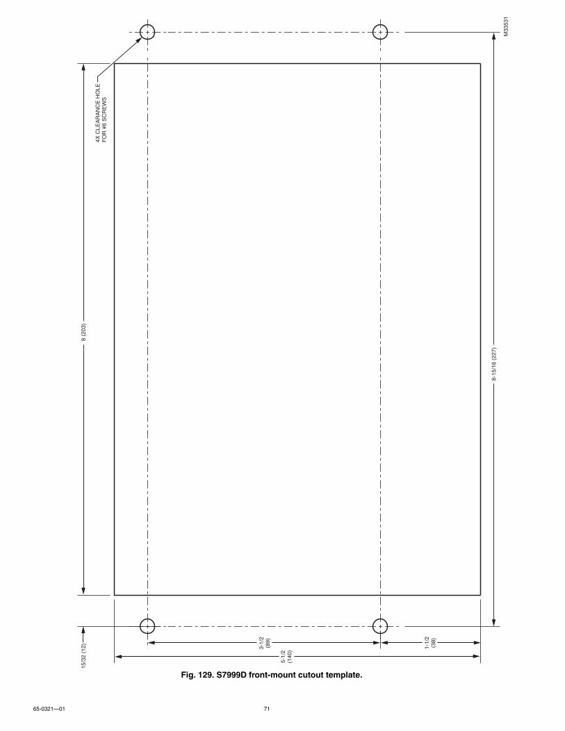
65-0321—01 71
Fig. 129. S7999D front-mount cutout template.
M33
531
4X C
LEA
RA
NC
E H
OLE
FO
R #
6 S
CR
EW
S
8 (2
03)
8-15
/16
(227
)
15/3
2 (1
2)
5-1/
2(1
40)3-
1/2
(89)
1-1/
2(3
8)

S7999D1048 COMBUSTION SYSTEM OPERATOR INTERFACE DISPLAY
65-0321—01 72

65-0321—01 73
Fig. 130. S7999D rear-mount cutout template.
7-1/
8 (1
81)
8-15
/16
(227
)
4X C
LEA
RA
NC
E H
OLE
FO
R #
6 S
CR
EW
S29
/32
(23)
4-41
/64
(118
)
2X 3
-1/2
(89)
2X 1
-5/6
4(2
7)
M33
532

S7999D1048 COMBUSTION SYSTEM OPERATOR INTERFACE DISPLAY
65-0321—01 74

S7999D1048 COMBUSTION SYSTEM OPERATOR INTERFACE DISPLAY
75 65-0321—01

S7999D1048 COMBUSTION SYSTEM OPERATOR INTERFACE DISPLAY
Automation and Control SolutionsHoneywell International Inc.
1985 Douglas Drive North
Golden Valley, MN 55422
customer.honeywell.com
® U.S. Registered Trademark© 2012 Honeywell International Inc.65-0321—01 M.S. 08-12Printed in United States