64 embedded antennas for uav …atmsindia.org/tech_papers/2016/064-embedded antennas for...
TRANSCRIPT
EMBEDDED ANTENNAS FOR UAV COMMUNICATIONS Selvanayaki K1, Rahul2, Samudra Das Gupta1, Dilip Y1
1 Scientist, Aeronautical Development Establishment (ADE), DRDO, Bangalore-75 2 Junior Research Fellow, Aeronautical Development Establishment (ADE), DRDO, Bangalore-75
E-mail: [email protected]; Phone: 080-25057890 Abstract
The concept of multiple antennas embedded as
part of UAV structure for meeting Omni
directional azimuth coverage of UAV
communication system is studied bringing out the
advantages of using such a concept. This study
brings out number of antennae elements required
for a typical Long-Ez UAV structure. A suitable
antenna element to meet the required coverage is
designed, simulated , fabricated & tested and the
results are presented. A typical wing leading edge
was fabricated and used to test the perturbation
caused by embedding the antenna as part of the
fabricated structure. The results are promising
and implementing such a concept is essential for
the current demanding needs of high data rate
communication systems and enhanced stealth
capability.
Index terms
Unmanned Air Vehicle (UAV), UAV structure,
wing leading edge
I Introduction
Conventionally, UAV antennae are externally
mounted in order to have better Line Of Sight
(LOS) with the ground systems and also to reduce
radiation pattern perturbation due to its proximity
with the UAV structure with different material
characteristics. Main requirement is achieving the
Omni directional coverage. The externally
mounted UAV antennae need to be
aerodynamically shaped in order not to disturb
the airflow and provide extra drag to the aircraft.
Such externally mounted UAV antennae design
need special care as they come under the category
of environmentally exposed and such care comes
with additional weight penalty. Present work
brings out the major advantages of going for
UAV structurally embedded antennae. It studies
the locations of antennae on a UAV structure,
brings out the number of antenna elements and
their required radiation characteristics to meet
Omni directional coverage as embedded inside
for a Long-Ez aircraft. A suitable antenna
element to meet the radiation requirement and the
bandwidth requirement is designed and radiation
characteristics are shown by simulation and by
experiment. The embedding of the antenna is
studied by positioning the antennae as per the
requirement in different sections of the UAV and,
by using the computational electromagnetic tool
the radiation pattern perturbation analysis is
carried out showing that it is possible to achieve
required antenna radiation performance. As the
implementation requires the concept to be taken
up during the aircraft fabrication itself, a sample
case of embedding an antenna in a typical wing
and the measurement results are shown. Proving
this paves the way for drastic reduction in Size,
Weight and Power (SWaP) requirement of UAV
communication system.
Antenna Test & Measurement Society (ATMS India-16)
01-03 Feb, 2016 1 Goa, India
II Multiple Embedded Antennae for UAV
Communication System and its advantages
RF link analysis of UAV communication system
should consider realistic onboard antenna gain as
mounted on to the UAV structure. Conventional,
single Omni antenna on elevated structure
mounted on a Long-Ez aircraft typically gives a
gain of -6dBi. Accordingly, for the given range,
for the given receiver sensitivity, and for the
given ground antenna gain the required
transmitting power is worked out to have enough
fade margin. Recent communication systems
demand for high data rate which in turn demands
for more transmitting power if conventional
single Omni antenna is used. Hence, if multiple
high gain antennas can be used, then the
requirement of increasing the transmitting power
can be eliminated. The number of antennas can be
anything depending on the gain requirement. In
this case, a long-Ez aircraft is considered and
depending on the masking effect, the available
transmitting power and the required fade margin
the number of antennae is decided. The following
gives the formula for finding the required
transmitting power
(1)
where Pt = Transmitting Power
Pr = Received Power
Gt = Airborne antenna gain
Gr = Ground antenna gain
FSL= Free Space Loss
FM=Fade Margin
20 10 20 10 92.5
(2)
where d is in Km, f is in GHz
For a typical data link for 200Km range at 5GHz,
the given receiver sensitivity is -85dBm @
16Mbps data rate, the given ground antenna gain
is 32dBi. To achieve minimum fade margin of
7dB with the conventional Omni antenna gain of
-6dBi in presence of the UAV, the required
transmitting power is 70W. This is a huge power
requirement and hence mechanically steerable
directional antenna system is used in many
unmanned aircrafts. But this comes with
additional weight penalty due to the mechanical
steering arrangement, radome to accommodate
the antenna etc., In addition to the weight penalty,
it gives additional drag to the aircraft. However,
if multiple directional antennae could be used
with switching capability meeting a gain
requirement of 2.5dBi in 360�, the required
transmitting power is only 10W. Hence, the
concept of having multiple antennae embedded as
part of the UAV structure is ideal for any UAV in
this era of high data rate communication systems
where new thinking is required at every design
input. In addition to Size Weight, and
Power(SWaP) saving it will also help in radiating
only in a narrow angle and hence will enhance the
stealth capability. Micro strip patch antenna is
chosen as the candidate antenna to be embedded
as it can meet the minimum gain required over
±45� angle. Intuitively, it might appear that 4
patch antennae mounted at 0 �, 90 � , 180 � , 270 �
will be enough to cater for Omni coverage
requirement as shown in figure 1. But the issues
are analysed in part IV.
Antenna Test & Measurement Society (ATMS India-16)
01-03 Feb, 2016 2 Goa, India

Figure 1: 4 patch antennae to give 360� coverage
III Antenna element for embedding inside the aircraft and the performance
The requirement of the antenna element for embedding as part of the UAV structure is that the gain shall be
greater than 2.5dBi after embedding inside the UAV structure over the beam width of ±45�. The most suitable
candidate antenna is patch antenna whose peak gain is approximately 7dBi with 3dB beam width of ±45�. A
wing leading edge is considered and the details are as shown in figure 2 where a=20cm, b=20cm,c=9cm with
the length of 1m.
Figure 2 Figure 3 Figure 4
Wing leading edge is modelled in FEKO as 2mm thick GFRP material with loss tangent of 0.019 and dielectric constant of 4.4. Figure 3 shows radiation pattern of wide band patch antenna & figure 5 shows the perturbed radiation pattern of wide band patch antenna at 5GHz when embedded inside the wing. It is evident that the shape of the wing leading edge perturbs the radiation pattern and the details are seen in the elevation and azimuth pattern as embedded in figure 5 & 6 and the minimum gain seen is 4dBi for ±45� coverage.
Antenna Test & Measurement Society (ATMS India-16)
01-03 Feb, 2016 3 Goa, India
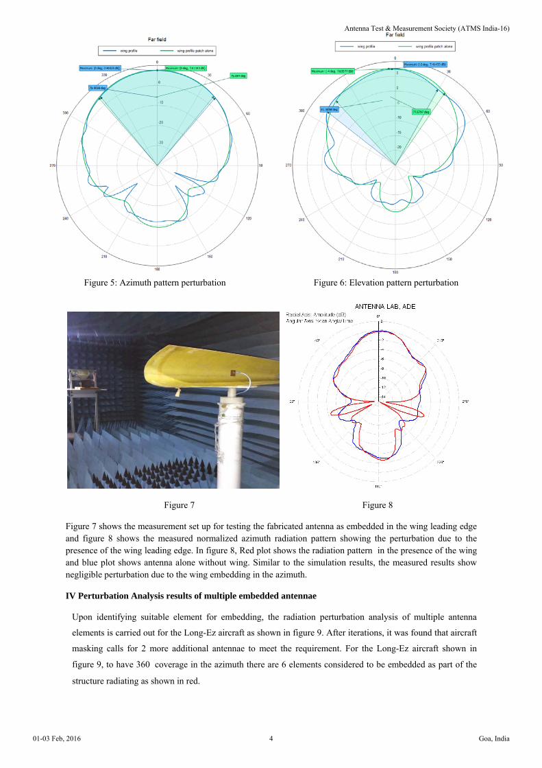
Figure 5: Azimuth pattern perturbation Figure 6: Elevation pattern perturbation
Figure 7 Figure 8
Figure 7 shows the measurement set up for testing the fabricated antenna as embedded in the wing leading edge and figure 8 shows the measured normalized azimuth radiation pattern showing the perturbation due to the presence of the wing leading edge. In figure 8, Red plot shows the radiation pattern in the presence of the wing and blue plot shows antenna alone without wing. Similar to the simulation results, the measured results show negligible perturbation due to the wing embedding in the azimuth.
IV Perturbation Analysis results of multiple embedded antennae
Upon identifying suitable element for embedding, the radiation perturbation analysis of multiple antenna
elements is carried out for the Long-Ez aircraft as shown in figure 9. After iterations, it was found that aircraft
masking calls for 2 more additional antennae to meet the requirement. For the Long-Ez aircraft shown in
figure 9, to have 360� coverage in the azimuth there are 6 elements considered to be embedded as part of the
structure radiating as shown in red.
Antenna Test & Measurement Society (ATMS India-16)
01-03 Feb, 2016 4 Goa, India
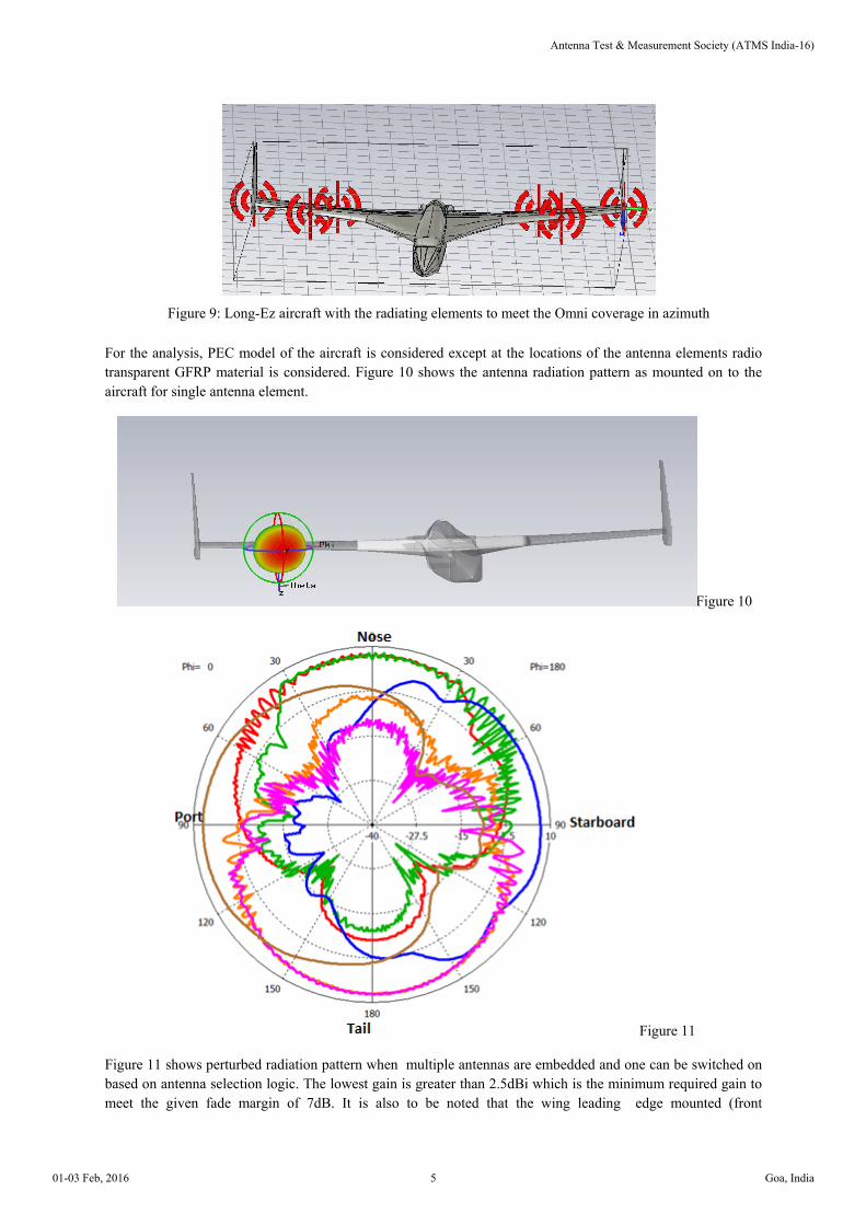
Figure 9: Long-Ez aircraft with the radiating elements to meet the Omni coverage in azimuth
For the analysis, PEC model of the aircraft is considered except at the locations of the antenna elements radio transparent GFRP material is considered. Figure 10 shows the antenna radiation pattern as mounted on to the aircraft for single antenna element.
Figure 10
Figure 11
Figure 11 shows perturbed radiation pattern when multiple antennas are embedded and one can be switched on based on antenna selection logic. The lowest gain is greater than 2.5dBi which is the minimum required gain to meet the given fade margin of 7dB. It is also to be noted that the wing leading edge mounted (front
Antenna Test & Measurement Society (ATMS India-16)
01-03 Feb, 2016 5 Goa, India

looking)antennae suffered (green and blue) suffered aircraft masking and so the idea of positioning two antennae are mandatory. However tail looking two antennae didn't suffer masking effect and so one is sufficient. In effect 5 antennae is good enough to have 360� coverage.
V Conclusion
The concept of having multiple antennas embedded as part of UAV structure for UAV communication system is studied and the advantages are brought out. A sample directional antenna performance as embedded inside the UAV wing leading edge is simulated and experimentally verified to be a promising candidate for structurally integrated antenna. The simulation results of antenna radiation perturbation for multiple embedded antenna for a PEC long-Ez aircraft are presented and minimum gain is shown to meet the requirements. This study also brought out the advantages of going for multiple high gain embedded antennae than single Omni directional antenna.
VI Reference
1. "Light weight agile beam antennas for UAVs", Wyman Williams, Chris Burton, EMS Technologies Inc.
Antenna Test & Measurement Society (ATMS India-16)
01-03 Feb, 2016 6 Goa, India