6360.17 - project implementation plan (pip) solid state ... · four slash unique local controlled...
TRANSCRIPT

ORDER 6360.17
PROJECT IMPLEMENTATION PLAN (PIP)
SOLID STATE RADAR BEACON DECODER (SSRBD)
A p r i l 9 , 1991
DEPARTMENT OF TRANSPORTATION FEDERAL AVIATION ADMINISTRATION
Distribution: )WW(NR/AP/SE/SI«3*»)-3; £2(GN)*3; A-Y(DE/AY)-3; A-X(AF)-3; Initiated By: ANR-HO ArfAT-OiLWy-^fAfAF-OiLTD)

04/09/91 6360.17
FOREWORD
This order provides management direction for the implementation and acceptance of the Solid State Radar Beacon Decoder (SSRBD) system into the National Airspace System (NAS). It defines the major functional responsibility levels, management direction, and overall program guidance to all responsible levels within the Federal Aviation Administration (FAA) for the procurement and implementation of the SSRBD.
This order has been prepared in accordance with (IAW) Order 1320.1, FAA Directives System, and FAA-STD-036, Preparation of Project Implementation Plans. It provides the appropriate level of technical guidance and direction to all levels of the FAA that are responsible for the SSRBD Program being implemented and integrated into the NAS.
Program Manager\fcpr Enj Route Radar
Page i (and ii)

04/09/91 6360.17
CHAPTER 1.
1. 2. 3. 4. 5.-19.
CHAPTER 2.
20. 21. 22. 23. 24. 25.-29,
CHAPTER 3.
30. 31. 32.
33. 34.-39.
CHAPTER 4.
40. 41. 42. 43.-49,
CHAPTER 5.
50. 51. 52. 53.
TABLE OF CONTENTS
Page No.
GENERAL 1
Purpose 1 Distribution 1 Definitions 1 Authority to Change This Order 1 Reserved 1
PROJECT OVERVIEW 3
Synopsis 3 Purpose 3 History 3 Authorization 4 Benefits 4 Reserved 4
PROJECT DESCRIPTION 5
Functional Description 5 Physical Description 5 System Requirements 5 Figure 3-1. Video Display Presentations 6 Figure 3-2. Functional Diagram and
Interfaces 7 Figure 3-3. SSRBD Cabinet 8 Figure 3-4. Decoder Control Assembly 9 Interfaces 10 Reserved 10
PROJECT SCHEDULE AND STATUS 13
Project Schedules and General Status 13 Milestone Schedule Summary 15 Interdependencies and Sequence 15 Reserved 15
PROJECT MANAGEMENT 17
Project Management, General 17 Project Contacts 25 Project Coordination 25 Project Responsibility Matrix 28 Table 5-1. SSRBD Project
Responsibility Matrix 28
Page iii

6360.17
54. 55. 56. 57. 58.-59.
CHAPTER 6.
60. 61.-69.
CHAPTER 7.
70. 71. 72. 73. 74.-79.
CHAPTER 8.
80. 81. 82. 83. 84. 85. 86. 87.-89,
CHAPTER 9.
90. 91. 92. 93. 94. 95. 96. 97. 98.-99,
CHAPTER 10.
Project Managerial Communications Implementation Staffing Planning and Reports Applicable Documents Reserved
PROJECT FUNDING
Project Funding Status, General Reserved
DEPLOYMENT
General Deployment Aspects Site Preparation Delivery Installation Plan Reserved
VERIFICATION
Factory Verification Checkout Contractor Integration Testing Contractor Acceptance Inspection (CAI) NAS Integration Testing Shakedown and Changeover Joint Acceptance Inspection (JAI) Reserved
INTEGRATED LOGISTICS SUPPORT
Maintenance Concept Training Support Tools and Test Equipment Supply Support Vendor Data and Technical Manuals Equipment Removal Facilities Automatic Test Equipment and Software Reserved
ADDITIONAL PROJECT IMPLEMENTATION ASPECTS
04/09/91
Page No.
30 30 31 33 34
35
35 35
37
37 37 38 38 38
39
39 40 40 41 41 41 42 42
43
43 43 43 43 44 44 44 44 44
45
100.-109. Reserved 45
APPENDIX 1. ACRONYMS/ABBREVIATIONS (2 Pages) 1
Page iv

04/09/91 6360.17
CHAPTER 1. GENERAL
1. PURPOSE. This order provides the overall guidance and direction for the orderly implementation of the Solid State Radar Beacon Decoder (SSRBD) Project. This Project Implementation Plan (PIP) establishes program management and project implementation procedures, and defines responsibilities governing the activities of specified organizations. It also identifies and defines the specific events and activities to be accomplished in order to successfully implement the SSRBD project. Each region will use the data contained within the PIP to develop a regional SSRBD Implementation Plan, which specifically, and at a much lower level of detail, addresses the actions required for that region.
2. DISTRIBUTION. This order is being distributed at branch level to the offices of the Program Director for Surveillance and the Program Manager for Advanced Automation; NAS System Engineering, Systems Maintenance, and Air Traffic Plans and Requirements Services; branch level to the regional Airway Facilities Divisions; the Engineering, Test, and Evaluation Service at the FAA Technical Center; and the FAA Academy and the FAA Logistics Center at the Mike Monroney Aeronautical Center; and limited distribution to the Airway Facilities and Air Traffic field offices.
3. DEFINITIONS. The terms, abbreviations, and acronyms used throughout this order are defined in appendix 1 unless otherwise specified or defined in reference documentation.
4. AUTHORITY TO CHANGE THIS ORDER. This order may be changed only by the Program Manager for En Route Radar, ANR-400. Requests for changes to this PIP should be directed to ANR-400, FAA Headquarters, 800 Independence Ave., SW, Washington, DC, 20591.
5.-19. RESERVED.
Chap 1 Par 1 Page 1 (and 2)

04/09/91 6360.17
CHAPTER 2. PROJECT OVERVIEW
20. SYNOPSIS.
a. Acquisition Concept. The acquisition of the SSRBD system is under a nationally managed FAA contract whereby the contractor will provide all services, materials, and data necessary to design, develop, fabricate, test, deliver, and install 103 systems in preparation for integration and optimization into the National Airspace System (NAS). The contractor will also deliver 10 systems to the FAA for installation by the FAA. The contract award includes a contractor furnished interim repair service for 2 years.
b. Contract Award. The SSRBD systems are being procured under a competitive fixed price contract. The contract was awarded to Wilcox Electric Co., on September 28, 1989. The contractor is to provide a total of 113 SSRBD systems.
21. PURPOSE. The prime purpose of the SSRBD is to provide a solid state radar beacon decoder at terminal facilities for use in the air traffic control. The SSRBD will functionally replace existing beacon vacuum-tube decoders and standardize decoder configuration requirements. The SSRBD will have reduced maintenance requirements with increased reliability and maintainability. The SSRBD will enhance maintenance efforts by increasing maintainability and reliability requirements. It will also fulfill the needs of the new generation workforce which is trained in state-of-the-art technology.
22. HISTORY. Air Traffic Control Beacon Interrogator (ATCBI) radar systems have served the NAS terminal facilities for over 25 years providing broadband beacon display information for use in air traffic control. Enhancements to these ATCBI systems have been on receivers, transmitters, and display equipment. A key element which has not been enhanced has been the vacuum-tube radar beacon decoder which provides unique video symbols for air traffic control. Most of these decoders are of the 1212 type which were established under FAA specification FAA-R-1212b. A few unique types also remain within the FAA inventory.
Chap 2 Par 20 Page 3

6360.17 04/09/91
23. AUTHORIZATION. The development and acquisition of the SSRBD equipment follows the guidelines of FAA solicitation, offer, and contract award DTFA01-89-C-00053 dated September 28, 1989, and FAA specification FAA-E-2825a, dated June 28, 1988. The SSRBD equipment is not a major system acquisition as defined by Order 1810.1, Major Acquisitions, nor is it covered by a systems requirements statement. The authorization rationale for the SSRBD equipment is supported by the Capital Investment Plan Air Traffic Control Radar Beacon System (ATCRBS) support program.
24. BENEFITS. The SSRBD will either replace ATCBI vacuum-tube decoders or provide new equipment at 82 terminal facilities providing improved operational performance and reduced maintenance requirements. Major goals to be achieved by the SSRBD acquisition are as follows:
a. Elimination of vacuum-tube decoders at terminal radar facilities.
b. Simplify and enhance maintenance techniques through the use of state-of-the-art technology.
c. Mean Time Between Failure will be 9,000 hours.
d. Mean Time To Repair will be 0.5 hour.
e. Automatic detection of emergency codes 7500, 7600, 7700.
f. Automatic switchover of power supplies in case of failure.
g. Raw video availability independent of common and non-common decoding circuits which may be used as a backup or to evaluate beacon targets.
h. Two full SSRBD systems can be contained in one standard cabinet decreasing the need for equipment space.
i. Provide Air Traffic with a new Four Slash/Slash Bloomer Slash video pattern for use in local air traffic control.
j. Low power consumption of less than 300 watts.
25.-29. RESERVED.
Chap 2 Page 4 Par 23

04/09/91 6360.17
CHAPTER 3. PROJECT DESCRIPTION
30. FUNCTIONAL DESCRIPTION. The SSRBD system shall provide a real-time (or in the case of an ASR-9, it will be max 2.2 seconds), Plan Position Indicator (PPI)-oriented output by decoding beacon replies of up to 40 (of 64) selectable, non-discrete Mode 3/a codes. It does this by accepting the codes from a ATCBI system, decodes them and then transforms these beacon pulses into various video presentations (see figures 3-1 and 3-2) as selected on a control box at a controller's position. One SSRBD system per beacon radar input. Each SSRBD system circuitry will feed up to four non-common decoders. Each non-common decoder with associated selector box will be able to feed beacon information to six displays in a parallel configuration (daisy chain). It shall also recognize and provide unique indicators for aircraft replying with the identification bit (SPI) and for the special emergency codes of 7700, 7600, and 7500.
31. PHYSICAL DESCRIPTION.
a. Equipment Cabinet. The cabinet which can house two complete systems is 76" tall, 24" wide and 30" deep (see figure 3-3). The cabinet when fully loaded will not exceed a concentrated floor loading of 700 pounds per square foot. The cabinet is desiqned for front access only. No open spaces are required at the sides or rear of the cabinet. A 4" square hole is located at the top rear of the cabinet to provide cable egress.
b. Control Box. The control box is 12" tall, 8" wide and 5" deep (see figure 3-4). The connecting cable will enter the rear of the assembly.
32. SYSTEM REQUIREMENTS. The SSRBD shall accept the specified input signals in accordance with Order 1010.51A, U.S. National Aviation Standard for Mark ATCRBS Characteristics, and shall meet the specified requirements of FAA-E-2825a, Specification for SSRBD. The SSRBD will receive signals from and provide signals to the equipment with which it is to be interconnected. Technical training shall be in accordance with FAA-STD-028, Contract Training Programs.
Chap 3 Par 30 Page 5

6360.17 04/09/91
FIGURE 3-1. VIDEO DISPLAY PRESENTATIONS
1. 2. 3* *• •
3«
O 9
/ • G «
«F *
10.
6
Sinale Slash , uncontrolled aircraft. Double Slash controlled aircraft. Triole Slash unique controlled aircraft. Four Slash unique local controlled aircraft Bloomer controlled aircraft IDEHT. Double Bleeraar 7700 ffltersency. Wide Blooiaer „ . 7600 tsmerfency. Double Slash Bloomer 75450 emergency. Bloomer Slash taicrae controlled aircraft IDEHT. Slash Bloomer Slash caique local controlled aircraft IDEHT
Chap 3 Par 3 0

0 4 / 0 9 / 9 1 6360 .17
DECODER DECODER |DECODER DECOOER CONTROL CONTROL iCONTROL CONTROL
T | £ 1 SCIP
ASR 9 REMOTE MICROWAVE LINK m
LINE iRBD
DRIVER SECONDARY
PAOAP m20 0 20000 FT BEATON v^g 1
COAX CABLE 0R COMPOSITE BEACON SYNC
MODE TRIGGERS
PPI PPI P?I PPI DISPLAY DISPLAY DISPLAY DISPLAY DISPLAY
I I t f FIGURE 2 FUNCTIONAL DIAGRAM AND INTERFACES
H T I f T 3 1
-MCDE ?/ft TPIG3ER
-MODE C TRIGGER
•BEACON SYNC "IGGER
• COMPENSATED
BEACON TRIGGER
-DISPLAY TRIGGER
DISPLAY VIDEO
DISPLAY /IQEO
Chap 3 Page 7 Par 30

6360.17 04/09/91
FIGURE 3-3. SSRBD Cabinet
GROUND , 4 INCH SOUARE -OR LUG CABL£ EGRESS CA8INE" . M I N & T ' C N
SWlTC- iNC STATUS
i^-zENT'LATiON
BLANK PANEL
ELECTRONICS DRAWER
(Located in Lower panel in single system locations)
REMOVABLE BLANK PANEL (FOR SECOND ELECTRONICS ORAWER)
CONVENIENCE LETS
Page 8 Chap 3 P a r 3 0

0 4 / 0 9 / 9 1 6360 .17
FIGURE 3 - 4 . DECODER CONTROL ASSEMBLY
r\
s : _ ; : STATE SAOAR SEACSN : H C : C H =
/ / / / ( I ,/ ' :D
SEL SYSTEM FAULT
it 1 t^J ID / / / / en
EMERSSNCri
SSL CSS CSS
IC SSL
CHAN
Hi in ID
SSL ID
/I ) )/ 'I ID
12.30 SSL SEL v*»
ID AUDZBL£ MJMM SEL ON
a
C i a 'i
'^MID
cr: = " S£" y
OF?
l ^ i / T T | ID
! / i / /'/ ( ID 3SL INDICATOR
TEST
RAH VIDEO
e/s
0 I D / S E L /
OFF CHAN
s ^ OFF
MODE
3/A-ys-c
Chap 3 P a g e 9 P a r TO
6360.17 04/09/91
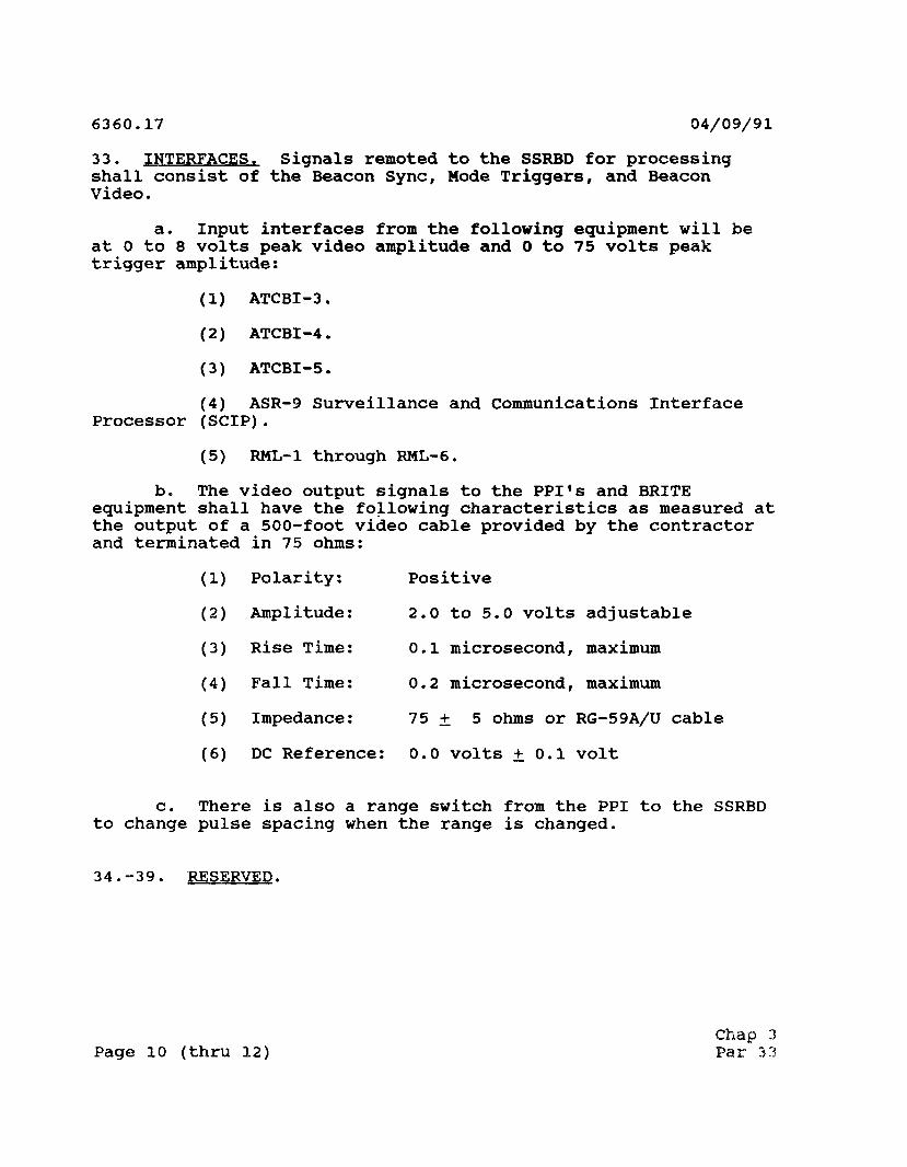
33. INTERFACES. Signals remoted to the SSRBD for processing shall consist of the Beacon Sync, Mode Triggers, and Beacon Video.
a. Input interfaces from the following equipment will be at 0 to 8 volts peak video amplitude and 0 to 75 volts peak trigger amplitude:
(1) ATCBI-3.
(2) ATCBI-4.
(3) ATCBI-5.
(4) ASR-9 Surveillance and Communications Interface Processor (SCIP).
(5) RML-1 through RML-6.
b. The video output signals to the PPI's and BRITE equipment shall have the following characteristics as measured at the output of a 500-foot video cable provided by the contractor and terminated in 75 ohms:
(1) Polarity: Positive
(2) Amplitude: 2.0 to 5.0 volts adjustable
(3) Rise Time: 0.1 microsecond, maximum
(4) Fall Time: 0.2 microsecond, maximum
(5) Impedance: 75 + 5 ohms or RG-59A/U cable
(6) DC Reference: 0.0 volts +0.1 volt
c. There is also a range switch from the PPI to the SSRBD to change pulse spacing when the range is changed.
34.-39. RESERVED.
Chap 3 Page 10 (thru 12) Par 3 3

04/09/91 6360.17
CHAPTER 4. PROJECT SCHEDULE AND STATUS
40. PROJECT SCHEDULES AND GENERAL STATUS. DELIVERY LOCATION & 8EQUENCE
a. SSRBD SITE DELIVERY DATAi (Installed by Contractor)
LOCATION SSRBD NCD SPARE SEQUENCE DEL. SYSTEMS BOXSS SETS Q&TE.
Kansas City, MO 1 2 1 1 04-91 FAA Academy, OK 1 2 1 2 06-91 Chicago, IL 2 8 1 3 06-91 FAA Logistics Center, OK 1 2 1 4 06-91
Milwaukee, WS 1 2 1 5 06-91 Oklahoma City, OK 1 4 1 6 06-91 Indianapolis, IN 1 2 1 7 06-91 Tulsa, OK 1 4 1 8 06-91 Louisville, KY 1 4 1 9 07-91 Memphis, TN 1 2 1 10 07-91 Covington, KY 1 2 1 11 07-91 New Orleans, LA 1 4 1 12 07-91 Dayton, OH 1 2 1 13 07-91 Shreveport, LA 1 4 1 14 07-91 Columbus, OH 1 2 1 15 07-91 DFW Airport, TX 3 10 1 16 08-91 Romulus, MI 1 4 1 17 08-91 Houston, TX 2 6 1 18 08-91 Cleveland, OH 1 2 1 19 08-91 Rio Grande Valley, T?XX 1 4 1 20 08-91 Pittsburgh, PA 1 4 1 21 09-91 San Antonio, TX 1 4 1 22 09-91 Buffalo, NY 1 4 1 23 09-91 El Paso, TX 1 4 1 24 09-91 Rochester, NY 1 3 1 25 09-91 Albuquerque, NM 1 4 1 26 09-91 Syracuse, NY 1 3 1 27 09-91 Tucson, AZ 1 4 1 28 09-91 Albany, NY 1 4 1 29 10-91 Phoenix, AZ 1 4 1 30 10-91 Boston, MA 2 8 1 31 10-91 Las Vegas, NV 1 4 1 32 10-91 Quonset Point, RI 1 3 1 33 10-91 San Diego, CA 2 8 1 34 10-91 Windsor Locks, CT 1 4 1 35 11-91 Los Angeles, CA 2 8 1 36 11-91 Islip, NY 1 2 1 37 11-91 El Toro, CA 2 8 1 38 11-91
Chap 4 Par 40 Page 13

H CTl hH* H H H H H H H H H N N N N N O I N N M f v l N O I C I N N N N N N N O J N f v l N N N N N N f N N N N N -* o
o I I I I I I I I I I I I I I I I I I I I I I I I I I I I I I I I I I I I I I I I I I I
r l H ( N N N N N N N r l H H r l H H r l H N O I N N N ( , ) n ( i n n n ' f ' i l , ^ T l l ' ) i ' f ' i t i n i n i f l i n m « H 0 I O H H H H H H H H H O O O O O O O O O O O O O O O O O O O O O O O O O O O O O O O O O O o a.
o w o 55 w t> m O r i N n t u n o O W co
rtr4Hr4r4Hrtr-<r4r4Hr-l H H H H H H H H H H H H H H H H r4HHrtHr-tr4r-irl
CO Q| o55
wX §
r j ^ ^ T f ( N V O C N C N r ~ ( N ^ ( N ' t ^ V O T f r O C N C O C O < N C O « N V O ^ f \ i r g ^ C S ^ ^ ^ f N J < N ( N r O V O V O - * ' ^ ( N < N ! ^ (J\ H
CO Q m «CO
swH CO
H H H H H M H H C N H H H H H C \ 0 ) H H M f > j H C > ] H N ( N H H H H H r v l H H H H H C N C > l f > J i - l i - f H C N J CI O H
CO 5H CO
co
E> fa EH U
EH
o
fa > i0 )+J H
H > H
EH fa
O
2 O H E-t <O
3
5* < 55 U is
^ *. •> «J 0 *M O - H X C
-H J-i M Id (0 (8 «J 43 S.4J J* U (0 C 0) 3 b O Z B
n CQ •< •< fa fa > o
CO * -0
k O id id «M H » ^ -O O id W 55 O
u 55
id
Cn-H -H J 0) H O
55 OS o
U ft
* fa
• H id
0) CD
5I id -P co fa
o o ^
fa
w 55 »
to - id
<l> S 3 O > 4 3 CO E-i •H
s id •H CD +> X « co
« - f t
(0 0) C G
••H RJ O 3 S b co c <u id Q co
(0 ft -H rH
o c a, to id 3 a) n c c c
• H id
id c a id id P EH KJ!
cu
id o
id o co
CTH 3 C - H 5
K - H > a S43
• W 10 . +J -H «J -P fa CO 55 CO
(0 H id 4J o EH
H
©
id ft

04/09/91 6360.17
b. Sites where installation by Wilcox are not planned:
Lihue, HI (ATCT) 11 2 2 1 TLABS, CA 55 2200 2 DFW Airport, TX 11 2 2 0 Denver, CO 11 4 4 0 Romulus, MI 11 4 4 0 Phoenix, AZ 11 4 4 0
Totals 10 38
Grand Total: 113 355
Summary:
Number of locations for the contractor installations: 81 CONUS : 72 Overseas : 9
Number of locations for the regional installations: CONUS : 5 Overseas : 1
41. MILESTONE SCHEDULE SUMMARY. Proposed installation locations are shown by delivery sequence in paragraph 40.
42. INTERDEPENDENCIES AND SEQUENCE. If warranted, scheduled deliveries and changes may be allowed 90 days prior to the actual delivery dates.
43.-49. RESERVED.
Chap 4 Par 40 Page 15 (and 16)

04/09/91 6360.17
CHAPTER 5. PROJECT MANAGEMENT
50. PROJECT MANAGEMENT. GENERAL. The SSRBD project is under the auspices of the office of the Associate Program Manager for En Route Special Projects, ANR-110. The project manager (PM) and designated staff members are responsible for procurement and implementation of the SSRBD from contract award through installation, checkout, and integration into the NAS. Matrix management will be used by the ANR-110 PM, who is the single focal point for all project activities, to monitor specific areas such as contractor performance and project implementation. The PM will utilize personnel from various FAA organizations to support program requirements within the guidelines provided by FAA policies, procedures, and directives. While there will be distinct lines of authority with regard to achieving project goals, informal communication and support among project responsible personnel will play a vital part in achieving the successful implementation of the SSRBD.
a. Key Individuals. Key individuals associated with the SSRBD project are as follows:
ANR-110 Don Johnson Project Manager ANR-110 James Duffer Technical Officer AAC-445B Kirk Miller FAA Logistics Center
- Engineering AAC-944B John Cole Training Coordinator ACE-425 Lee Riffel Regional Coordinator AGL-400 Charles Pere Regional Coordinator AEA-432 Alfred Arbeiter Regional Coordinator ANE-400 Bill Tretter Regional Associate
Program Manager ANM-400 Lee Slaughter Regional Coordinator ASO-400 Jim Garrett Regional Coordinator ASW-420 Bill Kolp Regional Coordinator AWP-420 Del Rupp Regional Coordinator AAC-485A Sheryl Johnson FAA Logistics Center
- Provisioning ASM-630 William Pryon Engineering Support/
Shakedown Testing ACN-220 Len Baker Test Director
(1) Project Manager. The division manager (ANR-lOO) has designated ANR-110 to serve as the PM for the SSRBD contract.
Chap 5 Par 50 Page 17

6360.17 04/09/91
(2) Technical Officer (TO). The PM has designated a member of the ANR-110 Radar Section as TO for the SSRBD contract. The TO will be responsible for all aspects of design, production, testing, delivery and management of the SSRBD installations. The TO is also responsible for all aspects of field implementation and will maintain close liaison with regional Technical Onsite Representatives (TOR) and contractor's installation teams in the regions, by providing technical guidance and direction within the scope of the contract.
(3) Quality Reliability Officer (PRO). A QRO is appointed by the Logistics Service (ALG-300) to administer the contract at the contractor's factory and ensure the adequacy of the quality control programs and inspection system.
(4) Technical Onsite Representative (TOR). The TOR, is designated by the regional Airway Facilities (AF) division as being accountable for ensuring that activities required in support of the installation of the SSRBD are accomplished in an orderly manner. The TOR is responsible for communication, coordination, and reaction to the responsibilities of the TO. The TOR will submit periodic technical reports to the TO describing progress at each site within the region.
(5) Airway Facilities Site Representative (AFSR). The AFSR is assigned by the regional AF division manager with primary responsibilities to work closely with the TOR, the contractor and AF sector personnel during the installation, testing, and acceptance phases at each SSRBD site.
b. SSRBD Project Responsibilities.
(1) Headquarters Responsibilities.
(a) ANR-110.
i. Provide project guidance to all offices, services, the Aeronautical Center, the FAA Technical Center, and the regions.
2. Ensure the timely implementation of the SSRBD into the operational environment in a way that minimizes costs and optimizes system performance.
3_. Identify requirements and staff offices or services necessary to support the installation and test efforts of the SSRBD.
Chap 5 Page 18 Par 50

04/09/91 6360.17
4_. Prepare, analyze, and distribute scheduling information to the regions, FAA Technical Center, Aeronautical Center, and the FAA Logistics Center.
5_. Ensure the baseline configuration for the SSRBD and provide suitable documentation to appropriate offices upon transition to operational status.
6_. Provide planning and guidance information to all activities which interface with the SSRBD for the timely implementation of support activity.
2. Provide site preparation requirements to the regions and the Aeronautical Center for monitoring the accomplishment of site activities leading toward the completion and acceptance of the site installations.
8. Be responsible for factory and field acceptance testing.
9_. Provide technical surveillance of the contractor in the design, development, production, testing, installation, integration, and documentation of hardware, firmware, and software for the SSRBD.
10. Develop the maintenance concept which entails providing for maintenance of the SSRBD by the appropriate in-house services and coordination with ANR-100.
11. Coordinate with the regions(s) for scheduling and monitoring the installation, and dismantling or disposal of equipment in accordance with Order 4800.2A, Utilization and Disposal of Excess and Surplus Property.
12. Ensure the availability of all software, firmware, and hardware interfaces required for SSRBD implementation.
13. Ensure the availability of funds and keep the contract within budget limitations.
14. Determine distribution of SSRBD documentation.
15. Ensure logistic support requirements in coordination with the Aeronautical Center, are planned, funded, and delivered in time to permit effective operational use of the SSRBD.
Chap 5 Par 50 Page 19

6360.17 04/09/91
16. Ensure logistic support requirements in coordination with the NAILS Program Division, ANS-400, and the Aeronautical Center, AAC-400, regional office Logistic divisions, are planned, funded, and delivered in time to permit effective operational use of the SSRBD.
17. Ensure the development of performance, maintenance, and calibration standards and procedures for the SSRBD.
18. Assist in and ensure the development of system operational changeover plans with AAT and the regions.
19. Provide configuration management support via the Configuration Control Board (CCB) and SSRBD Program Planning Groups.
20. Resolve all issues emanating from installation, checkout, and integration into the NAS of the SSRBD.
21. The TO will schedule meetings for all TOR's to provide briefings on the TOR's responsibilities and authority.
(b) Office of the Associate Administrator for Air Traffic (AAT).
1. Identify and document any additional operational requirements for the SSRBD and update Order 7110.65, Air Traffic Control, to include air traffic procedures for integration of the SSRBD into the NAS.
2. Ensure that all operational aspects of system implementation are satisfactorily resolved by the regions prior to operational changeover.
2. Coordinate with ASM-630 on the development of the SSRBD shakedown and changeover plans and procedures.
4. Provide technical coordination and support to ANR-110 on items associated with air traffic control functions, hardware configurations and operational requirements for interfacing with external air traffic systems.
5. Support ANR-110 in the area of air traffic control operational computer programs and generation of site documentation.
Chap 5 Page 20 Par 50

04/09/91 6360.17
6_. Provide membership to the SSRBD CCB and Planning Group.
7. Provide any special training requirements for facility personnel and specialist assigned to the regions or sites to the offices of training, air traffic requirements, and air traffic resource.
(c) Logistics Service tALG) fALG-200/300/400).
1. Provide procurement actions necessary to award and administer contract(s) for the acquisition of the SSRBD and related items to include, but not limited to, spares and calibration equipment.
2.. Provide FAA headquarters and in-plant contract administration. The headquarters contract officer has been designated as ALG-320.
3. Provide in-plant QRO's to ensure the adequacy of the quality programs and inspection systems and to administer the contract at the contractor's factories.
4. Provide surveillance of program management and contract administration.
5_. Provide policy and procedural guidance to regional AF divisions, Logistic divisions, and the Mike Monroney Aeronautical Center, for appropriate SSRBD property controls and record maintenance prior to operational use.
6_. Provide procedural guidance for the disposal or utilization of surplus material.
7. Provide support to the SSRBD CCB and planning group.
(d) Office of Training and Higher Education (AHT). Act as an alternate Contracting Officer's Technical Representative for training items only (AHT-330, FAA headquarters).
(e) Configuration Management and Engineering Support Division (ASE-600). Set the policies for how to control the changes in the configuration of the SSRBD and monitor the SSRBD configuration. Changes will be evaluated and controlled by the CCB.
Chap 5 Par 50 Page 21

6360.17 04/09/91
(f) National Airspace System Integrated Logistics Support (NAILS) Program Division (ANS-400). Responsible for assuring the timely integration of NAILS requirements into all aspects of project development and acquisition.
(2) System Engineering and Integration (SEP Contractor Responsibilities.
(a) Provide direct support to the ANR-110 to include, but not limited to the following areas:
1. SSRBD Deployment Readiness Review (DRR) checklist development and coordination.
2. SSRBD contractor developed documentation review, as assigned.
(3) Region Responsibilities. The regions will assist the TO with SSRBD project coordination, monitoring, and approving contractor installation and checkout efforts for the SSRBD field implementation. Some regions will also be responsible for installation of 10 systems (See chapter 4, paragraph 40b). Regional AF division managers are the responsible individuals for the SSRBD field implementation. To assist in this effort, each AF division manager will designate a TOR, and be responsible for the assignment of an AFSR.
(4) SSRBD Contractor Responsibilities. The SSRBD contractor is responsible for providing turnkey SSRBD installation for 103 systems. This includes design, development, testing, production, and installation of the system and providing spares, unique test equipment, training and all required documentation. The contractor also has the responsibility for 2 years of interim repair service.
(5) Mike Monroney Aeronautical Center. The Aeronautical Center will provide maintenance material, maintenance training support, and inputs to the maintenance requirements in coordination with the FAA Academy, FAA Logistics Center, the NAILS Program Division, and ANR-110. The Aeronautical Center will be provided with two SSRBD systems. They will be used by the FAA Academy for training, and the FAA Logistics Center for repair. Responsible organizations for each task listed in the following subparagraphs is in parentheses following the task description.
(a) Provide maintenance support for the SSRBD to include tools and test equipment, support equipment, facilities, technical data, transportation and handling. (AAC-400).
Chap 5 Page 2 2 Par 50

04/09/91 6360.17
(b) Act as the Contracting Officer's Technical Representative for training items only. This task is assigned to Terminal Radar Unit, AAC-944B, FAA Academy.
(c) Analyze training requirements, recommend approval or rejection of training program/materials, assign training responsibility, review and recommend approval of associated SSRBD training schedules, assignments, and programs. (AAC-940).
(d) Establish contractor conducted training programs for maintenance personnel. (AAC-940).
(e) Instruct and advise regions and training programs, schedules, and personnel assignments using Order 1380.40, Airway Facilities Sector Level Staffing Standard System, for guidance with manning standards established by Maintenance Operations Division, ASM-200. (AAC-940).
(f) Provide for technical supervision of onsite activities performed under the contract(s) at the FAA Academy. (AAC-940).
(g) Accept items delivered to the FAA Academy under the SSRBD contract. (AAC-52).
(h) Conduct provisioning effort for the SSRBD project. (AAC-400).
(i) Develop in conjunction with ANS, SEI contractor and ANR-110, logistics policies and plans for support of the SSRBD. (AAC-400).
(j) Participate, as requested by ANR, in the review of instruction books developed by the contractors. (AAC-940).
(k) Assure timely selections of necessary maintenance instructors to meet Mike Monroney Aeronautical Center training and staffing requirements. (AAC-940).
(1) Participate in planning activities for the transition of the SSRBD into the logistics inventory. (AAC-400).
(m) Training to be conducted initially at the Wilcox facility. Provide facilities for contractor training of FAA personnel. (AAC-940).
Chap 5 Par 50 Page 23

6360.17 04/09/91
(n) Establish facilities and item management control and accountability for all agency property received at AAC. (AAC-80).
(6) FAA Technical Center. The Secondary Surveillance Systems Branch (ACN-220) will provide the SSRBD Project Manager with the following support:
group. (a) Provide support to the SSRBD CCB and planning
monitoring. (b) Provide technical support in SSRBD contract
(c) Monitor the installation and checkout of the first SSRBD system.
(d) Conduct NAS OT&E/integration testing on the first SSRBD system and provide support to the program manager for all phases of test & evaluation (T&E).
(e) Support the development of test plans, test policy, standards, and test requirements.
(f) Support the accomplishment of a valid test program by reviewing conformity of test programs with Order 1810.4, FAA NAS Test and Evaluation Program, and standards, by reviewing test plans, test procedures, monitoring tests, and reviewing test analysis and reports.
(g) Provide the PM with OT&E/integration test plans, procedures, and reports.
(h) Support all testing activities up to first-site commissioning and additional sites as required.
(i) Provide a recommendation based on test results in support of the EXCOM DRR process to determine whether the SSRBD system should or should not be deployed.
(j) Jointly prepare SSRBD master test plan.
Chap 5 Page 24 Par 50

04/09/91 6360.17
(7) National Engineering Field Support Division (ASM-600). The Radar Engineering Branch (ASM-630), will provide the following support:
(a) Provide support to the SSRBD CCB and planning group.
(b) Act as Contracting Officer's Technical Representative for the technical instruction books and participate in all process reviews of the technical instruction book developed by the contractor.
(c) Monitor the installation and checkout of the first SSRBD system.
(d) Develop the shakedown test plan and procedures.
(e) Conduct shakedown testing on the first SSRBD system.
(f) Develop the maintenance handbook prior to first system commissioning.
(g) Provide a recommendation based on shakedown test results in support of the EXCOM DRR process to determine whether the SSRBD system should or should not be deployed.
(h) Provide engineering support for modifications (hardware/software) and documentation (technical instruction books) to commissioned facilities.
51. PROJECT CONTACTS. The primary points of contact for the SSRBD project are shown in paragraph 50a, SSRBD key individual list.
52. PROJECT COORDINATION. The following subparagraphs provide a brief overview of project support groups and their responsibilities to assist the TO in fulfilling assigned activities.
a. Technical Onsite Representative (TOR). The TOR's serve as focal points in the respective regions for the SSRBD implementation activities. As the PM's regional representative, they work closely with the PM and the headquarters TO. They are designated by the regional AF division manager and are
Chap 5 Par 50 Page 25

6360.17 04/09/91
accountable for ensuring that the SSRBD is implemented in an orderly manner. TOR's tasks include, but are not limited to, the following:
(1) Coordinate/manage regional deployment activities.
(2)personnel.
Provide guidance and direction to the FAA site
(3) Provide inputs and periodic technical reports describing the deployment progress at each site to the TO.
(4) Coordinate with Air Traffic as required, for test activities associated with the operational air traffic control systems.
(5) Ensure that the Joint Acceptance Inspection (JAI) and integration of the SSRBD into the NAS are accomplished, and ensure the AF sector manager or appropriate representative are present.
(6) Review and recommend approval contractor's Site Preparation Report (SPR).
(7) Confirm the beacon Pulse Repetition Frequency (PRF) of each installation site to the TO. PRF assignments will be forwarded to the contractor.
(8) Arrange for contractor site access.
(9) Complete FAA Form 256 SSRBD acceptance and submit the completed form to the TO.
(10) Submit installation logs and installation status reports, based on log entries, to the TO.
b. Site Representative. The AFSR's will be assigned by the AF division manager. This position will be the interface between the contractor, TOR, and sector personnel. Tasks include, but are not limited to, the following:
(1) Assist the contractor during the site surveys.
(2) Provide inputs to the TOR and logistics planning activities as they relate to site requirements.
(3) Record site performance data prior to beginning the installation.
Chap 5 Page 26 Par 52

04/09/91 6360.17
(4) Provide assistance to the TOR in direction and guidance to the contractor to efficiently and timely accomplish site preparation, installation, testing, and evaluation for the SSRBD.
(5) Witness the site preparation and installation.
(6) Participate in testing and integration into NAS.
(7) Witness the completion of FAA Form 256 for SSRBD acceptance.
(8) Assist in system field testing in accordance with the requirements of the test plans for the SSRBD and witness the JAI.
(9) Participate in the JAI.
c. Configuration Control Board. In accordance with Order 1800.8E, NAS Configuration Management, the CCB is the official agency-authorized forum to approve or disapprove baselines and changes to the baselines. There is a central NAS CCB to establish and control baselines and to administer configuration control. From this CCB, authority is delegated to lower-level CCB's to effectively administer proposed changes at the most appropriate level. All lower-level CCB's will be accountable to the NAS CCB which has been established through a charter defining its authority, responsibilities (including the specific documents over which the CCB has control), and membership. Decisions and directions are documented in Configuration Control Decisions (CCD), which either approves, disapproves, defers, or refers the change request to another CCB. When contractual action is required, the CCD serves as a basis for the preparation of a procurement request which is submitted to the contracting officer. The CCD may also be distributed to other Government agencies and serves as an official notification of CCB action. Representatives on the CCB are to include the various agency services/offices that have responsibilities to acquire, support, and operate the system. Other representatives may be invited to attend as required.
Chap 5 Par 52 Page 27
6360.17 04/09/91
(1) SSRBD CCB Membership (see table 5-1):
(a) Air Traffic Plans and Requirements Service (ATR).
(b) Air Traffic System Management (ATM).
(c) Program Director for Surveillance (ANR).
(d) FAA Technical Center (ACT).
(e) Configuration Management and Engineering Support Division (ASE-600).
(f) Logistics Service (ALG).
(g) Engineering Field Support Division (ASM-600)
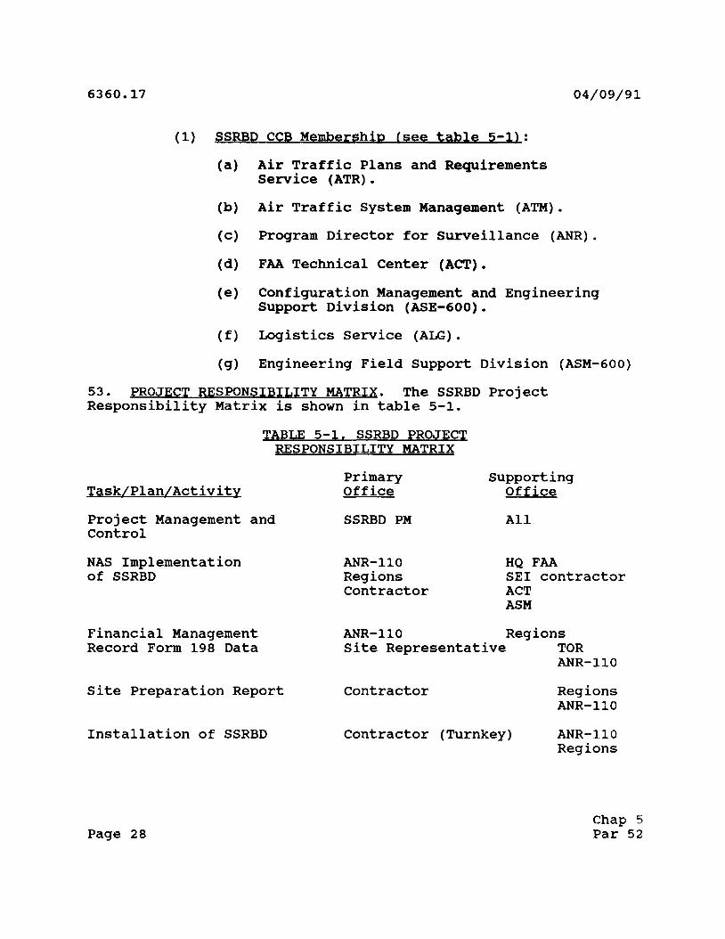
53. PROJECT RESPONSIBILITY MATRIX. The SSRBD Project Responsibility Matrix is shown in table 5-1.
TABLE 5-1. SSRBD PROJECT RESPONSIBILITY MATRIX
Task/Plan/Activity Primary Office
Supporting Office
Project Management and Control
SSRBD PM All
NAS Implementation of SSRBD
ANR-110 Regions Contractor
HQ FAA SEI contractor ACT ASM
Financial Management Record Form 198 Data
ANR-110Site Represent
Regions ative TOR
ANR-110
Site Preparation Report Contractor Regions ANR-110
Installation of SSRBD Contractor (Turnkey) ANR-110 Regions
Chap 5 Page 28 Par 52

04/09/91 6360.17
Task/Plan/Activitv
Acceptance Tests/Joint
Acceptance Inspection (JAI)
System OT&E Integration/ Testing
System Shakedown Testing
Site Specific Documentation
Maintenance Staffing
Maintenance Training
Configuration Management
Operational Integration
Contract Administration
Technical (Overall)
Primary Office
Contractor
TOR Site Representative
ACN-220 TOR Site Representative Air Traffic Control Tower Personnel
Contractor
ASM-630 ANR-110
Regions ASM-600 Contractor
ASM-200
AAC-944B
ASE-600 ANR-110
AAT ASM-630
ALG-300
ANR-110 ASM-600
Supporting Office
ANR-110
AAT ACN-220
ANR-110 AAT
AAT ACT Regions
ANR-110 AAT
ANR-110
AHT ANR-110 Regions
AAT ACN SEI contractor ALG
Regions ANR-110 ACN-220
ANR-110 Regions AAT
All
Chap 5 Par 53 Page 29

6360.17 04/09/91
Primary Supporting Task/Plan/Activity Office Office
Technical (Field) Regions ANR-110 ACN-220 AAC ASM-600
Logistic Support ANS-400 AAC-400 SEI Contractor ALG-300 ANR-110 ALG-200 Contractor
Quality Assurance ALG-425 ALL
54. PROJECT MANAGERIAL COMMUNICATIONS. To maintain effective and responsible control of overall SSRBD progress, reviews, conferences and working sessions will be held among the TO, TOR's and the contractor. Participation in these conferences and working groups by various other FAA offices will be requested at the discretion of the TO. In addition, routine status reports will be required.
55. IMPLEMENTATION STAFFING. The following personnel are responsible for the implementation of the SSRBD project.
a. Project Manager. The division manager (ANR-100) has designated ANR-110 to serve as PM for the SSRBD contract.
b. Technical Officer. The PM has designated a member of ANR-110 to be TO for the SSRBD contract. The TO will be responsible for all aspects of design, production, testing, delivery, installation, NAS integration and management of the SSRBD contract. The TO is also responsible for all aspects of field implementation and will maintain close liaison with regional TOR's and contractor installation teams in the regions.
c. Quality Reliability Officer (PRO). A QRO is appointed by ALG-300 to monitor production progress at the contractor's factory and ensure the adequacy of the quality control programs and inspection system.
Chap 5 Page 30 Par 53

04/09/91 6360.17
d. Technical Onsite Representative (TOR). The TOR is designated by the regional AF division as being accountable for ensuring that activities required in support of the SSRBD installation are accomplished in an orderly manner. The TOR is responsible for communication and coordination, in support of the TO. The TOR will submit to the TO weekly technical reports describing progress in each site within the region.
e. Test Directors (TD). The TD is appointed by ACN-220. Duties are described in Order 1810.4A, FAA NAS Test and Evaluation Program, Paragraph 9b.
56. PLANNING AND REPORTS. The successful implementation of the SSRBD project will be monitored by the use of the following:
a. Program Director Status Review Boards. The PM will brief higher level management on the status of project schedules, cost data, and technical topics. These reviews provide for top-level management control of the project. The PM may request the support of functional or contractor organizations in providing status and information on specific project topics.
b. Project Progress Reports. Monthly - the contractor will apprise the FAA of their assessment of contractual effort as of the date of the report, work scheduled for the next period and special problem areas including proposed solution.
c. Configuration Control and Status Accounting Report. Will provide data needed to identify configuration identification and determine the status of change proposals, deviations, and waivers, including implementation status.
d. Implementation Working Group. This group will meet periodically at FAA headquarters in Washington, D.C., or other agreed to locations to address both project issues and specific functional activities. Membership consists of the PM and headquarters TO. Other offices will be asked to participate as required. Action items generated at this meetings will be resolved by the project office or representatives from functional areas. Minutes of each meeting will be distributed to attendees and in regions and will include a summary of the topics discussed and description of all action items/resolutions.
e. Technical Onsite Representative Conferences. These conferences will be scheduled as necessary. These meetings are attended by TOR's from each region, the TO, and representative from headquarter organizations. The conference provides a forum to discuss and resolve project issues of special interest to the
Chap 5 Par 55 Page 31

6360.17 04/09/91
regions. Action items generated at these conferences focus on regional concerns end are resolved by the TO and designated TOR's or representativer from functional areas.
f. Design Reviews. Design reviews between ANR-110 and the SSRBD contractor will be held at scheduled times. These reviews will include the Preliminary Design Review (PDR) and a Critical Design Review (CDR). Other project design reviews addressing specific SSRBD activities shall be convened on a monthly basis. Participating organizations will be notified in advance on the date, time, and location by the PM. ANR-110 may be represented by the TO.
g. Regional Status Reporting. Status reports regarding technical progress will be submitted to the TO by each TPR. Routine reporting, as well as, responses to specific issues/requests will be addressed in these reports.
h. Puality and Reliability. The contractor's facility QRP will develop reports to the ANR-110 TP. Format, content, and schedule of these inputs are as directed by the ANR-110 TP.
i. Installation Phase Documentation. The basic documentation required are, the Installation Log and Installation Status Reports. These are described as follows:
(1) Installation Log. The FAA site representative (AFSR) will maintain a project installation log and make entries documenting the installation status, activities, and events for each site. Entries will be made for every visit to the site and/or communication/coordination with the contractor's onsite representative that have an impact on the contract. Items of consequence not adequately covered by written documents shall be included in the log, (e.g., unusual physical conditions encountered, oral protests, design deficiencies noted and actions taken, cause and extent of delays, etc.). The complete and factual entries will be made at the time of occurrence. Upon completion of the contracted work, the site representative will forward a copy of the log to the TPR. The TPR will forward a copy of the installation log to the TP. A copy of the same will remain at site.
(2) Installation Status Reports. These reports are designed to ensure that the CP, regional divisions, and the PM are abreast of the progress and/or problems at each location. The status report will be prepared and distributed by the TPR. Status reports will be supplied to the site representative and the regional AF division and AF sector managers, Contracting Officer, and PM as a minimum.
Chap 5 Page 32 Par 56

04/09/91 6360.17 ">
57. APPLICABLE DOCUMENTS,
POD Documents
DOD-D-1000 DOD-STD-100
FAA Documents DTFA01-89-C-00053 FAA-C-2454 FAA-D-2494b
FAA-E-2825a FAA-G-1375C FAA-STD-019 FAA-STD-036
FAA-STD-028 MIL-STD-1388-1A MIL-STD-1388-2A
MIL-STD-1561 NAS-MD-790 NAS-DD-1000A NAS-SS-1000
Order 7110.65 ABC-85-0084
Drawings, Engineering & Associated Lists Engineering Drawing Practices
Award/Contract for SSRBD Facility Site Preparation Technical Instruction Book Manuscript: Electronic, Electrical & Mechanical Equipment, Requirements for Preparation of Manuscript and Production of Books Specification for SSRBD Spare Parts Peculiar Lightning Protection for Facilities Preparation of Project Implementation Plans Contract Training Program Logistics Support Analysis DOD Requirements for Logistics Support Analysis Provisioning Procedures RMMS Interface Control Document NAS Level I Design Document NAS System Specification, Volumes I and III Air Traffic Control Handbook NAS Transition Plan, Volumes I and II
NAS Program Master Baseline Schedule Capital Investment Plan System Training Plan for SSRBD NAILS Integrated Logistics Support Plan for SSRBD
Chap 5 Par 57 Page 33

6360.17
FAA Prders
1050.1
1050.10
1320.1 1380.4
1800.8E 1800.58
1800.63 1810.4A 4250.9
4402.55 4560.IB
4620.3
4650.7 4800.2
6030.45 7032.5
58.-59. RESERVED.
04/09/91
Policies and Procedures for Considering Environmental Impacts Prevention, Control and Abatement of Environmental Pollution of FAA Facilities.
FAA Directives System Airway Facilities Sector Level Staffing Standard System
NAS Configuration Management National Airspace Integrated Logistics
Support Policy Nas Deployment Readiness Review Program FAA NAS Test and Evaluation Program Field Inventory Management and Replenishment Handbook FAA Procurement Manual - Real Property Policies and Procedures Covering the Provisioning Process During the Acquisition of FAA Materiel Initial Support for New or Modified Equipment Installation
Management of Project Material Utilization and Disposal of Excess and Surplus Property Facility Reference Data File SSRBD Air Traffic Service Pperational Requirements
chap 5 Page 34 Far 5 7

04/09/91 6360.17
CHAPTER 6. PROJECT FUNDING
60. PROJECT FUNDING STATUS. GENERAL. FAA offices, services, and regions must use the budgeting process to obtain funding for staffing, training, equipment, and associated development. Program Manager for En Route Radar, ANR-400, is the sole source of funding to the regions for the SSRBD project. The SSRBD project is within budget for the items specified in the SSRBD Award/Contract, DTFA01-89-C-00053. The Capital Investment Plan number is 26.16 (General Support). The SSRBD financial funding profile is covered within this broad category.
61.-69. RESERVED.
Chap 6 Par 60 Page 35 (and 36)

04/09/91 6360.17
CHAPTER 7. DEPLOYMENT
70. GENERAL DEPLOYMENT ASPECTS. The SSRBD contractor is responsible for the design, manufacturing, testing, and delivery of the SSRBD system to all field sites. The contractor is also responsible for conducting necessary site surveys, equipment installation, and testing of the integrated SSRBD which includes the conduct of installation, checkout, and interfacing with the NAS. The SSRBD Site Survey and Installation Schedule provides insight to the contractor's planned site surveys and installation activities. Prior to the physical deployment of SSRBD equipment to the first three sites, as a minimum, the FAA program office will be required to conduct a DRR. DRR's will be conducted in accordance with Order 1800.63, Nas Deployment Readiness Review Program. The DRR process should begin approximately 180 days prior to the tentative deployment dates shown in the SSRBD Equipment Delivery Report.
71. SITE PREPARATION. The requirements for SSRBD site preparation are as specified and shall be in accordance with section 3.5 of the Statement of Work (SOW). The site preparation for the SSRBD installation falls into two categories; contractor site preparation responsibilities and FAA site preparation responsibilities.
a. Contractor Responsibilities. For each location identified by the FAA, the contractor shall obtain specific site information required for installation of the SSRBD. The site specific data will be documented in a SPR and is subject to FAA approval.
b. FAA Responsibilities. FAA site preparation responsibilities are specified in Special Contract Requirements, of DTFA01-89-C-00053. Some of the major FAA's responsibilities are as follows: Paragraph numbers will reference FAA-E-2825a and the SOW.
(1) Configuration. The FAA will identify the SSRBD configuration to be installed by the contractor at each location.
(2) Airway Facilities Site Representative (AFSR). The FAA will designate an individual to represent the FAA during the installation process. The AFSR shall be the point-of-contact for all onsite activities.
(3) Equipment Locations. The FAA shall identify specific locations for the installation of all deliverable equipment. This includes the Air Traffic Control Tower operations area, equipment room, and the remote towers.
Chap 7 Par 70 Page 37

6360.17 04/09/91
(4) Obsolete Equipment Disposal. Disposal of all equipment removed during the replacement process shall be the responsibility of the FAA.
(5) Repairs. Any repairs to the ATCT that are necessary and become evident after removal of the old equipment shall be made by the FAA.
(6) Commissioning Inspection (JAI). A commissioning inspection (JAI) of each system shall be conducted by the FAA.
72. DELIVERY. As stated in paragraph 70, General Deployment Aspects, the contractor is responsible to provide all equipment, material, and personnel required for delivery. The proposed delivery schedule for the SSRBD is depicted in paragraph 40. All site preparation activities shall be completed prior to the SSRBD delivery dates. Reference section 3.5 of the SOW.
73. INSTALLATION PLAN. The contractor shall ensure the installation of each applicable SSRBD item described in accordance with section 3.5 of the SSRBD SOW. All equipment shall be installed in accordance with the contractor developed, FAA approved, installation procedure as contained in the Hardware Instruction Book. This handbook shall include all information, schematics, and drawings necessary to install, tuneup, checkout, and maintain the SSRBD system. An FAA approved draft manuscript of the Hardware Instruction Book, shall define the installation, integration, and checkout material as contained in the hardware instruction book, and will be used and verified during the installation of the first system. The approved final document shall be the installation standard for all SSRBD installations.
74.-79. RESERVED.
Chap 7 Page 38 Par 71

04/09/91 6360.17
CHAPTER 8. VERIFICATION
80. FACTORY VERIFICATION. The contractor portion of the SSRBD verification and testing will be conducted in phases; each phase is designed to provide increased assurance that required system objectives are being met. Verification will begin with Development Test and Evaluation (DT&E) and shall be complete upon the satisfactory verification of required system performance during in-plant acceptance testing and the operational test site. The SSRBD verification and testing phases are planned as follows:
a. Phase IA, Developmental Test and Evaluation, In-plant.
b. Phase IB, DT&E, Onsite Design Qualification Test.
c. Phase IIA, In-Plant Testing; Production Acceptance Test and Evaluation (PAT&E) on an SSRBD production unit for requirements verification prior to delivery, installation, and onsite testing.
d. Phase IIB, PAT&E, Operational-Site Acceptance Test.
(1) The contractor developed, and the FAA approved SSRBD Test Plan as required by the SSRBD contract, number DTFA0189-C-00053 defines the above verification phases and how individual procedures will also be developed and approved to verify the requirements of the SSRBD specification, FAA-E-2825a.
(2) In addition, the test program requires Reliability Growth testing to rapidly mature the system design, the Federal Communication Commission (FCC) type acceptance of the design to ensure electromagnetic compatibility with the operating environment. The software testing requirements of FAA-E-2825a and the SOW will be described in the contractor developed and FAA approved Software Test Plan and Test Procedures.
(3) The SSRBD Test Plan also contains the Verification Requirements Traceability Matrix (VRTM) as required by FAA-E2825a, paragraph 4.2.9. This matrix provides a functional decomposition of the SSRBD specification requirements, which associates each specification paragraph with the method of verification. In the case of verification by test, the particular contractor test procedure that will demonstrate compliance in accordance with FAA-E-2825a, section 4, is also indicated. In the case of verification by analyses or data, the matrix delineates the contract or specification reference that requires or permits the verification to be performed by analysis
Chap 8 Par 80 Page 39

6360.17 04/09/91
or data submittal. Verifications by inspection will be performed by in-process inspection. All other references are to specification paragraphs. These are either not quantitative, do not require verification, or are not qualitatively verifiable.
(4) The contractor will be responsible for the development and obtaining FAA approval on the following SSRBD Test and Verification documentation.
(a) Software test plans and procedures.
(b) SSRBD test plan.
(c) Test procedures for:
1. Design qualification.
2. Type tests.
2- Production tests.
4. Preliminary tests.
5. Contractor integration tests.
6_. Onsite tests.
(5) For specific information related to Par. 80d(4), refer to section 4, Quality Assurance Provisions, of the SSRBD specification, FAA-E-2825a.
81. CHECKOUT. This is the first stage of onsite testing and is performed by the contractor on an SSRBD subsystem level basis only. Checkout testing verifies the hardware system integrity of the contractor delivered equipment prior to interfacing with any site equipment. These test will usually consist of alignment, correct display presentation, voltage, and signal checks at all external output points, and checks for grounds or short conditions at all external input points to ensure that interfaces to external equipment are appropriate.
82. CONTRACTOR INTEGRATION TESTING. The contractor shall perform the SSRBD integration testing utilizing FAA approved procedures and checklists for accomplishing all site adaptation and integration activities. Contractor integration testing will subject the SSRBD to the test site and live air traffic control
Chap 8 Page 40 Par 80

04/09/91 6360.17
environments. This testing will verify the integrated functional areas within the complete system, and verification of the SSRBD in a site specific environment. Testing will be conducted using live inputs and recorded or simulated inputs as necessary for the verification of the SSRBD in an operational environment.
83. CONTRACTOR ACCEPTANCE INSPECTION (CAI). Upon completion of contractor integration testing (ref. paragraph 82) the CAI will be conducted by the TOR or his/her representative. The contractor demonstrates that the system complies with all technical and functional requirements of the contract specification and amendments, and that all deliverables are onsite and operable. The completion of the CAI designates acceptance of the equipment by the FAA.
84. NAS INTEGRATION TESTING. NAS integration testing will be conducted to verify the NAS system-level and operational requirements using live and/or simulated data and/or interfaces. ACN-220 is the office of primary responsibility for NAS integration testing. SSRBD NAS integration testing will include, as a minimum, running diagnostics, interface tests with appropriate equipment, loading of site operational software, and running of test procedures to verify the system-level and operational requirements. The PM is responsible either directly or by tasking ACN-220, for the preparation and availability of the SSRBD Integration Test Plan and supporting test procedures.
85. SHAKEDOWN AND CHANGEOVER, shakedown testing will be conducted to confirm that when the system is operated and maintained by operational personnel in the operational environment all requirements are met. ASM-630 will develop the Shakedown Test Plan and Procedures and is the office of primary responsibility for shakedown testing. Prior to the JAI, the TOR will verify the following:
a. All required SSRBD technical documentation is available at the site.
b. Spares are available at the site, in the required range and depth, to support the site's operational schedule.
c. Adequate sector maintenance personnel have completed the SSRBD Training Course and demonstrated proficiency in the equipment.
Chap 8 Par 82 Page 41

6360.17 04/09/91
86. JOINT ACCEPTANCE INSPECTION (JAI). A JAI shall be conducted in accordance with Order 6030.45, Facility Reference Data File. The purpose of a JAI is to ensure that each SSRBD meets specified requirements for operation and maintenance, and has demonstrated that the facility is ready to be commissioned. The Joint Acceptance Board may include representatives from; ANR-110, regional offices, Air Traffic headquarters, sites and other representatives as appropriate. A copy of the results of the JAI must be forwarded to the TO for submission to the PM. The JAI documentation is comprised of FAA Forms 6030.18 through 6030.25. The SSRBD will be designated as operationally certified upon the satisfactory completion of the JAI. The satisfactory completion of the JAI designates acceptance of the equipment by the FAA AF Sector.
87.-89. RESERVED.
Chap 8 Page 42 Par 86

04/09/91 6360.17
CHAPTER 9. INTEGRATED LOGISTICS SUPPORT
90. MAINTENANCE CONCEPT. The SSRBD will be supported by two levels of maintenance, site and the FAA Logistics Center. The maintenance status of the SSRBD will be monitored by operational personnel. When a system fault is observed, a maintenance technician will diagnose the problem to a failed Line Replaceable Unit (LRU). The faulty LRU will be removed from the SSRBD system and a serviceable LRU will be installed. The technician will forward the failed LRU through channels to Wilcox Electrical Co., 2001 N.E. 46th St., Kansas City, MO 64116, during the 2 years of interim repair service. The extent of contractor/depot maintenance will be defined by the contractor's utilization of the Logistic Support Analysis (LSA) program in accordance with MIL-STD-1388, to define LRU's, and proposed repairable LRU's will then be supported in the supply system based on the development of the LSA master files. After this 2 years of interim maintenance, all LRU's requiring repair will be routed through the FAA Logistics Center, in Oklahoma City, OK. The Integrated Logistics Support Plan (ILSP) describes in more detail the Integrated Logistics Support (ILS) for the SSRBD.
91. TRAINING. Training will be developed and administered in accordance with the SSRBD specification, FAA-E-28725a, FAA-STD-028 and as presented in the System Training Plan for the SSRBD. The System Training Plan is developed in accordance with the NAS Training Plan and presents training planning information, including training requirements and schedules, for the SSRBD project. It is a document for communicating and coordinating planned training data requiring FAA review, modification, and approval. It contributes to and serves as the foundation for the transition and site-specific design training plans developed by the SEI contractor. Revisions to the SSRBD training plan will be made as required by changes in project projections and actual project events. The training data base shall be updated as required and will be maintained in Washington, D.C., by the SEI contractor, (Logicon).
92. SUPPORT TOOLS AND TEST EQUIPMENT. There have been no special tools or test equipment identified as requirements for the SSRBD system.
93. SUPPLY SUPPORT. The SSRBD system will have two methods of supply support, they are: Site stock and Depot stock. Site stock consists of one spare card of each type card used in the SSRBD system. Depot stock consists of back up stock for the site spared items and selected items not expected to fail frequently enough to warrant site sparing.
Chap 9 Par 90 Page 43

6360.17 04/09/91
94. VENDOR DATA AND TECHNICAL MANUALS. Technical manuals will be obtained in accordance with FAA-D-2494b. Engineering drawings will be prepared in accordance with DOD-D-1000 and DOD-STD-100. Course materials will be developed in accordance with FAA-STD-028. Parts lists in hard copy used for provisioning will be formatted in accordance with FAA-G-1375c for spare parts peculiar and MIL-STD-1561 for all oth??r lists.
95. EQUIPMENT REMOVAL. The FAA has full responsibility for the removal and disposal of obsolete equipment. Disposition of equipment removed prior to/during installation shall be in accordance with Order 4800.2A, Property Utilization and Disposal of Excess and Surplus Personal Property. Regions will identify the necessary requirements for removal of obsolete ATCBI decoders when SSRBD becomes operational. The SSRBD program office will initiate action, consistent with ALG policy and with their concurrence, to allow immediate disposal of displaced equipment.
96. FACILITIES. Facility modification/transition will be addressed in more specific detail in the appropriate regional Facility Transition Plans.
97. AUTOMATIC TEST EQUIPMENT AND SOFTWARE. The automatic test equipment used by the contractor, and approved by the FAA is the Hewlett Packard 3065. The configuration of the contractors' HP 3065 has been checked against the FAA supplied documents and both HP 3065 are configured with all boards in like slots.
98.-99. RESERVED.
Chap 9 Page 44 Par 94

04/09/91 6360.17
CHAPTER 10. ADDITIONAL PROJECT IMPLEMENTATION ASPECTS
100.-109. RESERVED.
Chap 10 Par 100 Page 45

04/09/91 6360.17
APPENDIX 1. ACRONYMS/ABBREVIATIONS
1. PURPOSE. The purpose of this glossary is to provide the definition of terms, acronyms and abbreviations used in this order.
ACT AF AFSR ALG ANR ASR ATCBI ATCRBS ATCT CAI CCB CCD CDR DOT DRR DT&E FAA FCC IAW ILS ILSP ISP JAI LRU LTC MaxTTR MDT MTBF MTTR NAILS
NAS OT&E PDR PIP PM PPI PVD QRO RML
FAA Technical Center Airway Facilities Airway Facilities Site Representative Logistics Service Program Director for Surveillance Airport Surveillance Radar Air Traffic Control Beacon Interregator Air Traffic Control Radar Beacon System Air Traffic Control Tower Contractor Acceptance Inspection Configuration Control Board Configuration Control Decision Critical Design Review Department of Transportation Deployment Readiness Review Development Test & Evaluation Federal Aviation Administration Federal Communications Commission In-Accordance-With Instrument Landing System Integrated Logistics Support Plan Integrated Support Plan Joint Acceptance Inspection Line Replaceable Unit Local Tower Cab Maximum-Time-To-Repair Maintenance Data Terminal Mean-Time-Between Failures Mean-Time-To-Repair National Airspace Integrated Logistics Support
National Airspace System Operational Test and Evaluation Preliminary Design Review Project Implementation Plan Project Manager Plan Position Indicators Plan View Display Quality Reliability Officer Remote Microwave Link
Page 1

6360.17
SCIP
SEI-TCO
SOW SPR SSRBD STD STE T&E TDB TBS TD TO TOR VRTM
04/09/91
Surveillance and Communications Interface Processor
System Engineering and Integration-Technical Center Operations
Statement of Work Site Preparation Report Solid State Radar Beacon Decoder Standard Support and Test Equipment Test & Evaluation To-Be-Determined To-Be-Supplied Test Director Technical Officer Technical Onsite Representative Verification Requirements Traceability Matrix
*U S Government Printing Office 1991 — 522-101/40079 Page 2