6298-01 - deep discharge recovery procedure for aircraft
TRANSCRIPT

Deep Discharge Recovery Procedure for Aircraft Batteries
Aerospace & Defence
Document No.
9602 – 6298 Rev 01

Document No. 9602-6298 rev 01 - 2 - 03/01/13
1.0 INTRODUCTION
This document covers the deep discharge recover procedure for EnerSys valve regulated aircraft
batteries.
2.0 SAFETY ADVICE
Warning!
Short circuit currents will exceed 2000 amps; all tools must be insulated. Care must be taken
with all items of metal in clothing and jewellery, e.g. Buckles, zips, rings, watches, chains etc.
Caution!
Always ensure that the battery lid is securely fitted prior to charging.
Monobloc terminal nuts are NOT to be re-tightened.
Note!
1) A dedicated lead acid battery room is not required for servicing. A normal electrical
workshop may be used and under certain conditions the battery can be serviced in a nickel
cadmium battery room.
2) Use a Fluke Digital Voltmeter Series 70 or equivalent, to carry out Open Circuit Voltage
(OCV) checks.
3.0 DEEP DISCHARGE RECOVERY PROCEDURE
(Refer to Deep Discharge Recovery Flowchart)
If a battery is heavily discharged, recognised by an OCV of less than 20 volts and usually due to low
current drain, it is said to be in a deeply discharged state. The EnerSys battery should recover from
deeply discharged state using the recovery procedure detailed below.
(a.) Discharge the battery at the rate detailed in table 1 at 20 ± 2°C to an end voltage of 12 volts.

Document No. 9602-6298 rev 01 - 3 - 03/01/13
Battery Rating Discharge current
18 Ampere-hour 2.6 Amps
25 Ampere-hour 3.8 Amps
37 Ampere-hour 4.9 Amps
40 Ampere-hour 5.0 Amps
Table 1
(b.) Charge the battery using a constant current charger set at the current detailed in table 2 for 15
hours.
Note!
The 15 hours constant current charge may be split into 2 or 3 smaller periods such as 2 by 7.5 hour
charge periods or 3 by 5 hour charge periods.
Battery Rating Charge current
18 Ampere-hour 2.0 Amps
25 Ampere-hour 3.0 Amps
37 Ampere-hour 3.9 Amps
40 Ampere-hour 4.0 Amps
Table 2
Note!
Before the voltage stabilises at around 31V it may rise as high as 35V as the gas recombination
process starts. This occurrence is normal and will not degrade the battery.
(c.) Allow the battery to stand battery open circuit at 20 ± 2°C for 16 to 24 hours after constant current
charge.
(d.) Discharge the battery at the appropriate rates detailed in table 3 at 20 ± 2°C to an end voltage of 20
volts or 48 minutes whichever is achieved first. Record the terminal voltage at the end of the
discharge.
Battery Rating Discharge current
18 Ampere-hour 18 Amps
25 Ampere-hour 25 Amps
37 Ampere-hour 37 Amps
40 Ampere-hour 40 Amps
Table 3
Note!
Discharge duration should not be allowed to exceed 48 minutes.
(e.) If the discharge duration is in excess of 48 minutes, recharge the battery as detailed in paragraph
4.0. Record the test result on the battery label and return to service.

Document No. 9602-6298 rev 01 - 4 - 03/01/13
(f.) If the discharge duration is less than 48 minutes, recharge the battery in accordance with paragraph
4.0.
(g.) Allow the battery to stand open circuit for a minimum of 4 hours before repeating steps (a) to (e).
(h.) If this second discharge duration is still below 48 minutes the battery should be rejected and
disposed of in accordance with local regulations.
IT IS STRONGLY RECOMMENDED THAT DEEP DISCHARGES ARE PREVENTED OR KEPT TO A MINIMUM.
4.0 CONSTANT POTENTIAL CHARGING
Note!
CONSTANT POTENTIAL CHARGERS MUST BE CAPABLE OF SUPPLYING A MINIMUM OF 10
AMPS.
Charge the battery using a constant potential charger capable of supplying 28.0 volts with a current limit
set at 10 amps.
The higher the available current the faster the battery will recharge, typical duration values are shown table
4 below: -
Battery Capacity Charge Duration
@ 10 A @ 20 A @ 30A
18 Ampere-hour 4 3 2
25 Ampere-hour 6 5 4
37 Ampere-hour 8 7 6
40 Ampere-hour 8 7 6
Table 4
Document No. 9602-6298 rev 01 - 5 - 03/01/13
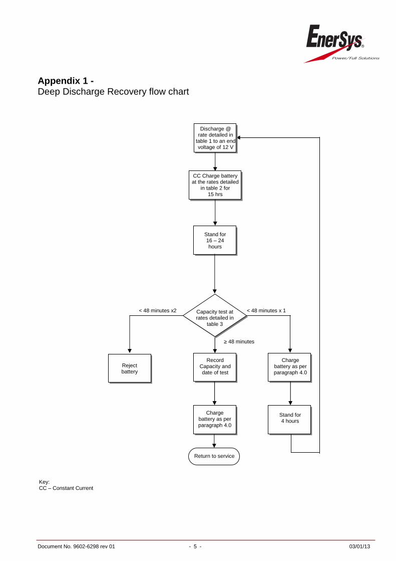
Appendix 1 - Deep Discharge Recovery flow chart
Charge battery as per paragraph 4.0
Return to service
Record Capacity and date of test
Charge battery as per paragraph 4.0
< 48 minutes x2 < 48 minutes x 1
≥ 48 minutes
Capacity test at rates detailed in
table 3
Stand for 16 – 24 hours
Reject battery
Stand for 4 hours
Key: CC – Constant Current
Discharge @ rate detailed in
table 1 to an end voltage of 12 V
Volts
CC Charge battery at the rates detailed
in table 2 for 15 hrs

Document No. 9602-6298 rev 01 - 6 - 03/01/13
EnerSys Newport, Stephenson Street, Newport, South Wales. NP19 4XJ Tel: + 44 (0) 1633 277 673 Fax: + 44 (0) 1633 281 787 www.enersys.com