6.2 trusses: method of joints and zero-force members · 6.2 trusses: method of joints and...
TRANSCRIPT

6.2 Trusses: Method of Joints and Zero-Force Members
6.2 Trusses: Method of Joints and Zero-Force Members Example 1, page 1 of 3
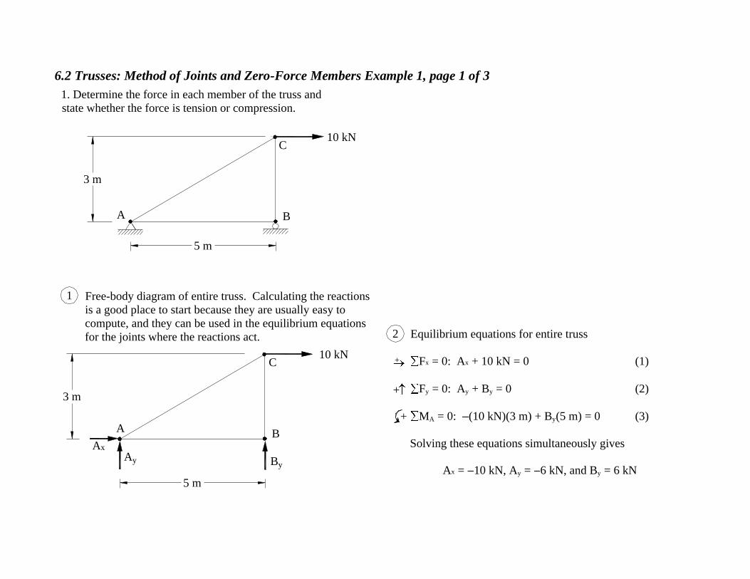
Free-body diagram of entire truss. Calculating the reactions
is a good place to start because they are usually easy to
compute, and they can be used in the equilibrium equations
for the joints where the reactions act.
3 m
5 m
C
BA
10 kN
1
Equilibrium equations for entire truss
F x = 0: A
x + 10 kN = 0 (1)
F y = 0: A
y + B y = 0 (2)
M A = 0: (10 kN)(3 m) + B
y(5 m) = 0 (3)
Solving these equations simultaneously gives
A x = 10 kN, A
y = 6 kN, and B y = 6 kN
2
+
+
+
Ax
Ay By
3 m
5 m
C
BA
10 kN
1. Determine the force in each member of the truss and
state whether the force is tension or compression.

6.2 Trusses: Method of Joints and Zero-Force Members Example 1, page 2 of 3
Equilibrium equations for joint C. It is a good idea
to assume all members in tension (forces point away
from the joint, not towards it). Then, after solving
the equilibrium equations, you will know
immediately that any member force found to be
negative must be compression.
F x = 0: 10 kN F
AC sin = 0 (4)
F y = 0: F
AC cos F BC = 0 (5)
4
+
+
10 kNC
FBC
FAC
5 m
3 m
A B
CGeometry5Free-body diagram of joint C3
= tan-1 ( ) = 59.04°53
Using = 59.04° in Eqs. 4 and 5 and solving
simultaneously gives
F AC = 11.66 kN (T) Ans.
and
F BC = 6.0 kN = 6.0 kN (C) Ans.
Writing "(T)" after the numerical value shows that
the member is in tension. We had arbitrarily
assumed member BC to be in tension. We then
found that the member force was negative, so we
know that our assumption was wrong. Member BC
is in compression, and we show this by writing a
positive "6.0" followed by "(C)".
6

6.2 Trusses: Method of Joints and Zero-Force Members Example 1, page 3 of 3
By = 6 kN
B
FBC = 6 kN
FAB
A
C
B
10 kN
6.0 (C)
0
11.66 (T)
Free-body diagram of joint B7
An "Answer diagram" summarizes the analysis
of the entire truss (All forces are in kN).
9 10Equilibrium equation for joint B
F x = 0: FAB = 0
Solving gives
FAB = 0 Ans.
The force FBCis directed toward
the joint because member BC is
known to be in compression.
8
66
10
+

6.2 Trusses: Method of Joints and Zero-Force Members Example 2, page 1 of 7
2. Determine the force in each member of the truss and state
whether the force is tension or compression.
2 kip 2 kip4 kip
14 ft
10 ft 10 ft 10 ft 10 ft
A
B C D
E
F G H

6.2 Trusses: Method of Joints and Zero-Force Members Example 2, page 2 of 7
HGF
E
DCB
A
10 ft10 ft10 ft10 ft
14 ft
4 kip 2 kip2 kip
Ax
AyEy
Free-body diagram of entire truss.
Calculating the reactions is usually a
good way to start the analysis.
1
Equilibrium equations for entire truss
F x = 0: A
x = 0 (1)
F y = 0: A
y + E y kip kip kip = 0 (2)
M A = 0: 2 kip)(10 ft) (4 kip)(20 ft) (2 kip)(30 ft) + E
y(40 ft) = 0 (3)
Solving simultaneously gives
A x = 0, A
y = 4.0 kip, and E y = 4.0 kip.
2
+
+
+

6.2 Trusses: Method of Joints and Zero-Force Members Example 2, page 3 of 7
Free-body diagram of joint E. This joint is
chosen because only two unknown forces are
present. Thus we know that we can solve for
these forces because two equations of
equilibrium are available for the joint. Note
also that we assume that both unknown forces
are in tension (directed away from the joint).
Using = 54.46° in Eqs. 4 and 5 and solving
simultaneously gives
F DE = 2.857 kip (T) Ans.
F EH = 4.916 kip = 4.916 kip (C) Ans.
We arbitrarily assumed member EH to be in tension. We
then found that the member force was negative, so we
know that our assumption was wrong. Member EH is in
compression, and we show this by writing a positive
"4.916" followed by "(C)".
Equilibrium equations for joint E
F x = 0: F
DE F EH cos = 0 (4)
F y = 0: F
EH sin 4 kip = 0 (5)
= tan-1 ( ) = 54.46°
Geometry
Ey = 4 kip
E
+
+
FEH
FDE
H
ED
14 ft
10 ft
3
6
7
4
51410

6.2 Trusses: Method of Joints and Zero-Force Members Example 2, page 4 of 7
Use a free-body diagram of joint H next because only
two member forces are unknown.
F EH = 4.916 kip (C)
F DE = 2.857 kip (T)
Equilibrium equations for joint H
F x = 0: F
GH (4.916 kip) cos 54.46° = 0 (6)
F y = 0: F
DH + (4.916 kip) sin 54.46° = 0 (7)
Solving simultaneously gives
F GH = 2.858 kip = 2.858 kip (C) Ans.
and
F DH = 4.0 kip (T) Ans.
As before, we assume
that the unknown
member forces (GH and
DH in this instance) are
tension, so are directed
away from the joint.
The force in member
EH has already been
found to be 4.916 kip
compression, so it is
directed towards the
joint, not away from it.
Free-body diagram of joint H
F
A
G H
B C D
E
2 kip 2 kip4 kip
H
= 54.46°
F EH = 4.916 kip (C)
FGH
FDH
8 9
10
11
+
+

6.2 Trusses: Method of Joints and Zero-Force Members Example 2, page 5 of 7
4 kip 2 kip2 kip
EDCB
HG
A
F
F EH = 4.916 kip (C)
F DE = 2.857 kip (T)
Use a free-body
diagram of joint
D because only
two member
forces are
unknown.
Free-body diagram of joint D
As before, we assume that the unknown
member forces are tension, so are directed away
from the joint. The forces in members DH and
DE have already been found to be tension and
so are directed away from the joint.
FGH = 2.858 kip(C)
FDE = 2.857 kip
FDGFDH = 4.0 kip
FCD
2 kip
= 54.46°
12
13
14
++
15 Equilibrium equations for joint D
F x = 0: F
CD F DG cos(54.46°) + 2.857 kip = 0 (8)
F y = 0: F
DG sin(54.46°) + 4.0 kip 2 kip = 0 (9)
Solving simultaneously gives
F CD = 4.286 kip (T) Ans.
and
F DG = 2.458 kip = 2.458 kip (C) Ans.
6.2 Trusses: Method of Joints and Zero-Force Members Example 2, page 6 of 7
F DE = 2.857 kip (T)
F EH = 4.916 kip (C)
F
A
G H
B C D
E
2 kip 2 kip4 kip
FGH = 2.857 kip(C)
FDG = 2.458 kip (C)
FDH = 4.0 kip (T)
FCD = 4.286 kip (T)
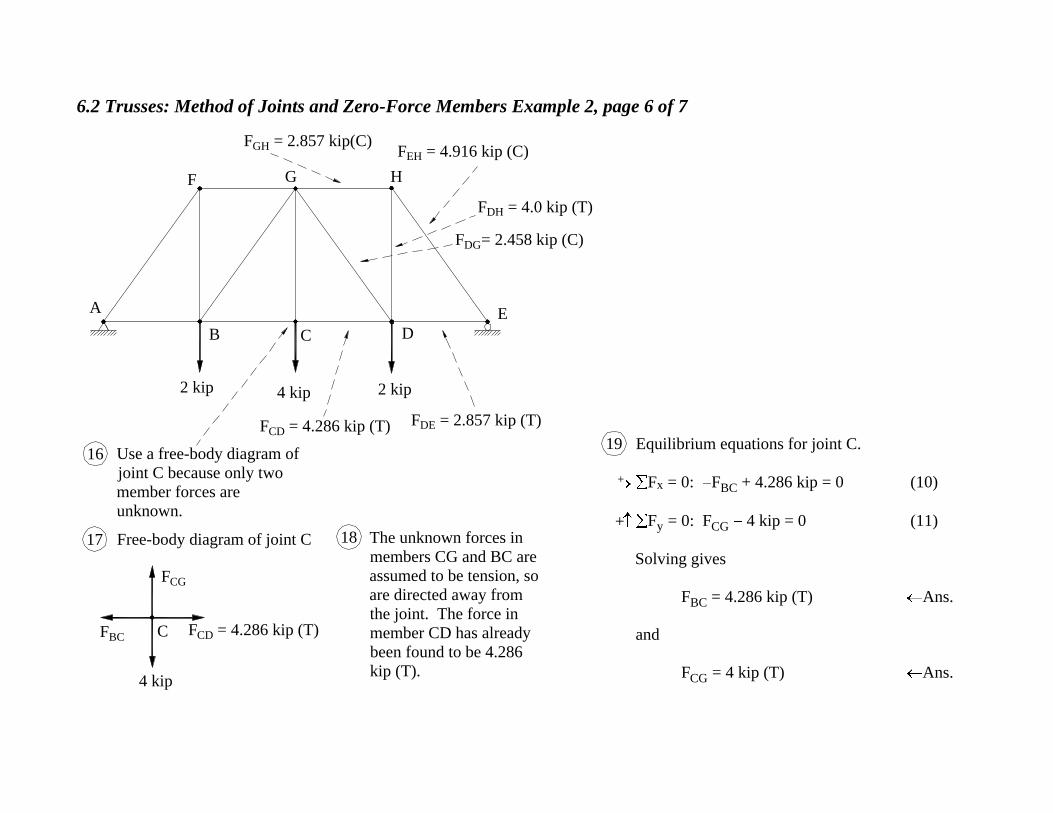
Use a free-body diagram of
joint C because only two
member forces are
unknown.
Free-body diagram of joint C The unknown forces in
members CG and BC are
assumed to be tension, so
are directed away from
the joint. The force in
member CD has already
been found to be 4.286
kip (T).
Equilibrium equations for joint C.
F x = 0: F
BC + 4.286 kip = 0 (10)
F y = 0: F
CG 4 kip = 0 (11)
Solving gives
F BC = 4.286 kip (T) Ans.
and
F CG = 4 kip (T) Ans.
4 kip
C
FCG
FCD = 4.286 kip (T)FBC
16
17 18
19
+
+

6.2 Trusses: Method of Joints and Zero-Force Members Example 2, page 7 of 7
HGF
E
DCB
A
4 22
All remaining bar forces follow from symmetry.
Answer diagram
4.92 (C)
2.86 (C)2.86 (C)
4.0
0 (
T)
4.0
(T
)
4.0
(T
)
4.92
(C
)
2.46
(C
)
4.29 (T)4.29 (T)
2.46 (C)
2.86 (T) 2.86 (T)
All forces in kips.
20
4 4

6.2 Trusses: Method of Joints and Zero-Force Members Example 3, page 1 of 4
3. Determine the force in each member of
the truss and state whether the force is
tension or compression.
10 ft
12 ft
60°
30°
400 lb
900 lb
A
B C
DE

6.2 Trusses: Method of Joints and Zero-Force Members Example 3, page 2 of 4
900 lb
400 lb
10 ft
12 ft
60°
30°B C
DE
Ex
Ey
Because AB is a two-force member, the line of
action of FAB must pass through A and B.
Free body-diagram of entire truss
Equilibrium equations for entire truss
F x = 0: F
AB sin 60° + E x + (900 lb) cos 30° = 0 (1)
F y = 0: F
AB cos 60° + E y + (900 lb) sin 30° 400 lb = 0 (2)
MC = 0: (400 lb)(10 ft + F AB cos 60°(10 ft) + E
x(12 ft) = 0 (3)
Solving simultaneously gives
F AB = 347.8 lb
E x = 478.2 lb,
E y = 123.9 lb
21
3
+
+
+
FAB

6.2 Trusses: Method of Joints and Zero-Force Members Example 3, page 3 of 4
Free-body diagram of joint D. Joint D is chosen
because only two member forces are unknown there.
Equilibrium equations for joint D
F x = 0: F
DE = 0 (4)
F y = 0: F
BD 400 lb = 0 (5)
Solving gives
F BD = 400 lb (T) Ans.
F DE = 0 Ans.
Free-body diagram of joint C. Joint C is chosen because
only two member forces are unknown there.
Equilibrium equations for joint C
F x = 0: F
BC +779.4 lb = 0 (6)
F y = 0: F
CE + 450 lb = 0 (7)
Solving gives
F BC = 779.4 lb (T) Ans.
F CE = 450.0 lb (T) Ans.
D
400 lb
FDE
FBD
FCE
CFBC
(900 lb) sin 30° = 450.0 lb
(900 lb) cos 30°= 779.4 lb
4
5
6
7
8
9
The unknown forces
have been assumed to
be tension. The unknown
forces have
been assumed
to be tension.
+
+
+
+

6.2 Trusses: Method of Joints and Zero-Force Members Example 3, page 4 of 4
Free-body diagram of joint B. Only one
member force is unknown at this joint.
Equilibrium equations for joint B
F x =0: F
BE cos (347.8 lb) sin 60°
+ 779.4 lb = 0 (8)
= tan-1 ( )
= 50.19°
Geometry
Using = 50.19° in Eq. 8 and then solving gives
F BE = 746.9 lb = 747 lb (C) Ans.
Answer diagram (all forces in lb)
B
FAB = 347.8 lb
FBD = 400 lb
FBE
FBC = 779.4 lb
60°
124
478
ED
CB
60°
400
30°900 lb
CB
E
10 ft
12 ft400 (T)
779 (T)
450 (T)
747 (C)
10
11
12
13
14
+
1012
0
347.8 lb

6.2 Trusses: Method of Joints and Zero-Force Members Example 4, page 1 of 9
30°
4. Determine the force in each member of the truss and state whether
the force is tension or compression. The truss is symmetric.
2 kip
2 kip
2 kip
2 kip
2 kip
6 ft 6 ft 6 ft 6 ft 6 ft 6 ft
A
B CD
EF G H
I J
K
60°
60°

6.2 Trusses: Method of Joints and Zero-Force Members Example 4, page 2 of 9
60°
K
JI
HGFE
DCB
A
6 ft6 ft6 ft6 ft6 ft6 ft
2 kip
2 kip
2 kip
2 kip
2 kip
AxAy Dy
Free-body diagram of entire truss
Equilibrium equations for entire truss
F x = 0: A
x = 0
F y = 0: A
y + D y 2 kip
2 kip 2 kip 2 kip 2 kip = 0
M A = 0: 2(kip)(6 ft) 2 kip(12 ft)
2(kip)(18 ft) 2 kip(24 ft)
2(kip)(30 ft) + D y(36 ft) = 0
Solving simultaneously gives
A x = 0
A y = 5 kip
D y = 5 kip
+
+
+
2
1
30° 60°
6.2 Trusses: Method of Joints and Zero-Force Members Example 4, page 3 of 9
Dy = 5 kipAy = 5 kip
Ax = 0
2 kip
2 kip
2 kip
2 kip
2 kip
A
B CD
EF G H
I J
K
60°
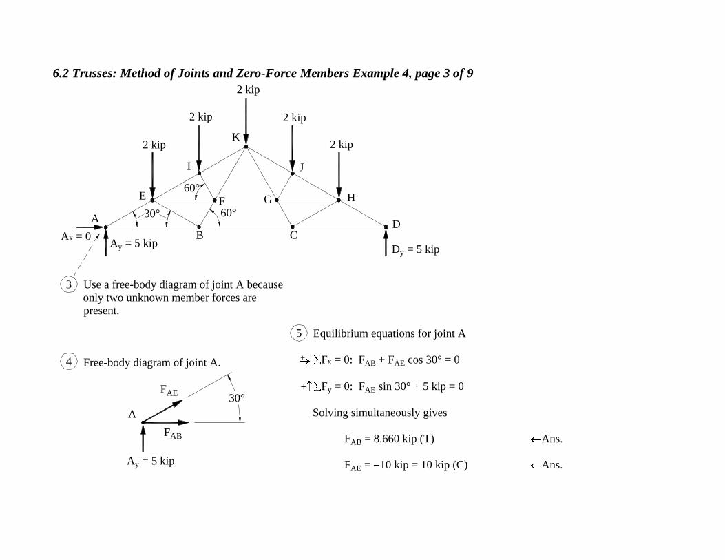
Use a free-body diagram of joint A because
only two unknown member forces are present.
Free-body diagram of joint A.
Equilibrium equations for joint A
F x = 0: F
AB + F AE cos 30° = 0
F y = 0: F
AE sin 30° + 5 kip = 0
Solving simultaneously gives
F AB = 8.660 kip (T) Ans.
F AE = 10 kip = 10 kip (C) Ans.Ay = 5 kip
A
30°FAE
FAB
3
4
5
+
+
30° 60°

6.2 Trusses: Method of Joints and Zero-Force Members Example 4, page 4 of 9
Three unknown member forces are present at joint I, but
two of them, F EI and F
IK, are collinear, so summing
forces perpendicular to F EI and F
IK would give an
equation with F FI as the only unknown.
Free-body diagram of joint I
Geometry of members at joint I
Equilibrium equations for joint I
F y = 0: F
FI sin 90° (2 kip) sin 60° = 0
Solving gives
F FI = 1.732 = 1.732 kip (C) Ans.
= 30° + 60°
= 90°
So member FI is
perpendicular to the x axis.
Thus the member force F FI
lies on the y axis.
60°
K
JI
HGFE
DCB
A
2 kip
2 kip
2 kip
2 kip
2 kip
Ax = 0Ay = 5 kip
Dy = 5 kip
2 kip
I
y
x
FIK
FEI
FFI
30°
60°E
I
A
F
30°
= 60°
60°
6
7
8
9
+
30° 60°
60°
x
y

6.2 Trusses: Method of Joints and Zero-Force Members Example 4, page 5 of 9
Use the same technique at
joint F as was used at joint I:
sum forces perpendicular to
collinear members BF and FK.
Geometry of members at joint F
Free-body diagram of joint F
Equilibrium equations for joint F
F y = 0: F
EF sin 60° (1.732 kip) sin 60° = 0
Solving simultaneously gives
F EF = 1.732 kip (T) Ans.
60°
K
JI
HGFE
DCB
A
2 kip
2 kip
2 kip
2 kip
2 kip
Ax = 0Ay = 5 kip
Dy = 5 kip
FE
60°
60°
I
B
60°
= 180° (60° + 60°) = 60°
10
11
12
13
F FI = 1.732 kip (C)
(already known)
F
60°y
xF
FI = 1.732 kip (C)
FBF
FEF
FFK
60°
+
30° 60°

6.2 Trusses: Method of Joints and Zero-Force Members Example 4, page 6 of 9
F AE = 10.0 kip (C)
(already known)
At joint E, now only two member
forces, F EI and F
EB, are unknown.
Free-body diagram of joint E Equilibrium equations for joint E
F x = 0: (10 kip) cos 30° + F
EI cos 30° + F BE cos 30° + 1.732 kip = 0
F y = 0: (10 kip) sin 30° + F
EI sin 30° F BE sin 30° 2 kip = 0
Solving simultaneously gives
F EI = 9.0 kip = 9.0 kip (C) Ans.
F BE = 3.0 kip = 3.0 kip (C) Ans.
60°
K
JI
HGFE
DCB
A
2 kip
2 kip
2 kip
2 kip
2 kip
Ax = 0Ay = 5 kip
Dy = 5 kipF
EF = 1.732 kip (T)
(already known)
2 kip
E
60°
30°
30°30°F
EF = 1.732 kip (T)
FBE
FEI
FAE = 10 kip(C)
14
15 16
+
+
30° 60°
6.2 Trusses: Method of Joints and Zero-Force Members Example 4, page 7 of 9
60°
K
JI
HGFE
DCB
A
2 kip
2 kip
2 kip
2 kip
2 kip
Ax = 0
Ay = 5 kip
Dy = 5 kip
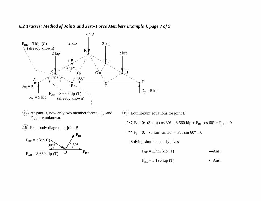
F BE = 3 kip (C)
(already known)
F AB = 8.660 kip (T)
(already known)
Free-body diagram of joint B
At joint B, now only two member forces, F BF and
F BC, are unknown.
Equilibrium equations for joint B
F x = 0: 3 kip) cos 30° 8.660 kip + F
BF cos 60° + F BC = 0
F y = 0: 3 kip) sin 30° + F
BF sin 60° = 0
Solving simultaneously gives
F BF = 1.732 kip (T) Ans.
F BC = 5.196 kip (T) Ans.
B
60°30°
FBC
FBF
FBE = 3 kip(C)
F AB = 8.660 kip (T)
17
18
19
30° 60°
+
+
6.2 Trusses: Method of Joints and Zero-Force Members Example 4, page 8 of 9
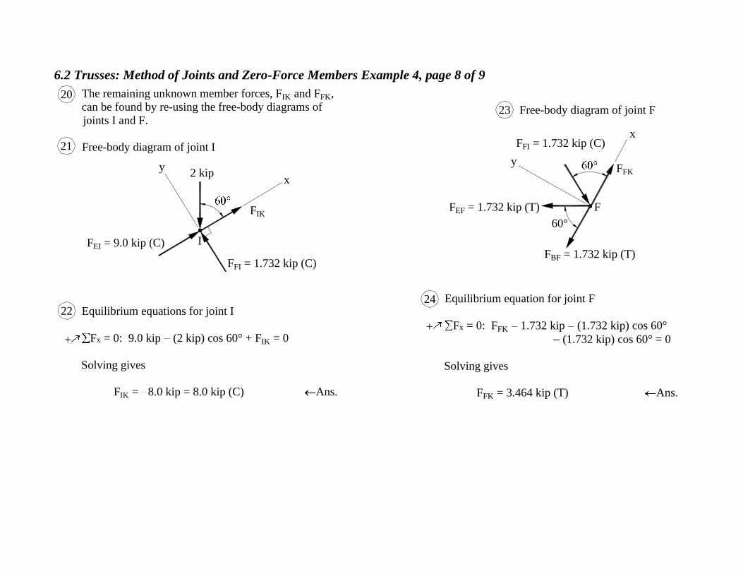
The remaining unknown member forces, F IK and F
FK,
can be found by re-using the free-body diagrams of
joints I and F.
Free-body diagram of joint I
Equilibrium equations for joint I
F x = 0: 9.0 kip (2 kip) cos 60° + F
IK = 0
Solving gives
F IK = 8.0 kip = 8.0 kip (C) Ans.
Free-body diagram of joint F
Equilibrium equation for joint F
F x = 0: F
FK 1.732 kip (1.732 kip) cos 60°
(1.732 kip) cos 60° = 0
Solving gives
F FK = 3.464 kip (T) Ans.
F FI = 1.732 kip (C)
F EF = 1.732 kip (T)
F BF = 1.732 kip (T)
F EI = 9.0 kip (C)
FFI = 1.732 kip (C)
FIK
xy
I
2 kip
60°
FFK
y
F
x
20
22
23
24
21
+
+

6.2 Trusses: Method of Joints and Zero-Force Members Example 4, page 9 of 9
K
JI
HGFE
DCB
A
By symmetry, all forces on the right half of
the truss are also known.
Answer diagram
All forces in kips
2
2
2
2
2
8.66 (T) 8.66 (T)5.20 (T)
10.00 (C)
9.00 (C)
8.00 (C)
8.00 (C)
9.00 (C)
10.00 (C)
3.00 (C)
1.732 (T) 1.732 (T)
1.732 (T) 1.
732
(T)
3.00 (C)
1.73
2 (T
)
1.732 (T)
3.46
(T
)
3.46 (T)
25
5 5

6.2 Trusses: Method of Joints and Zero-Force Members Example 5, page 1 of 8
5. Determine the force in each member of the truss and
state whether the force is tension or compression.
4 ft 2 ft 4 ft
2.5 ft
1 ft
100 lb
A
B
C
D
E
F
6.2 Trusses: Method of Joints and Zero-Force Members Example 5, page 2 of 8
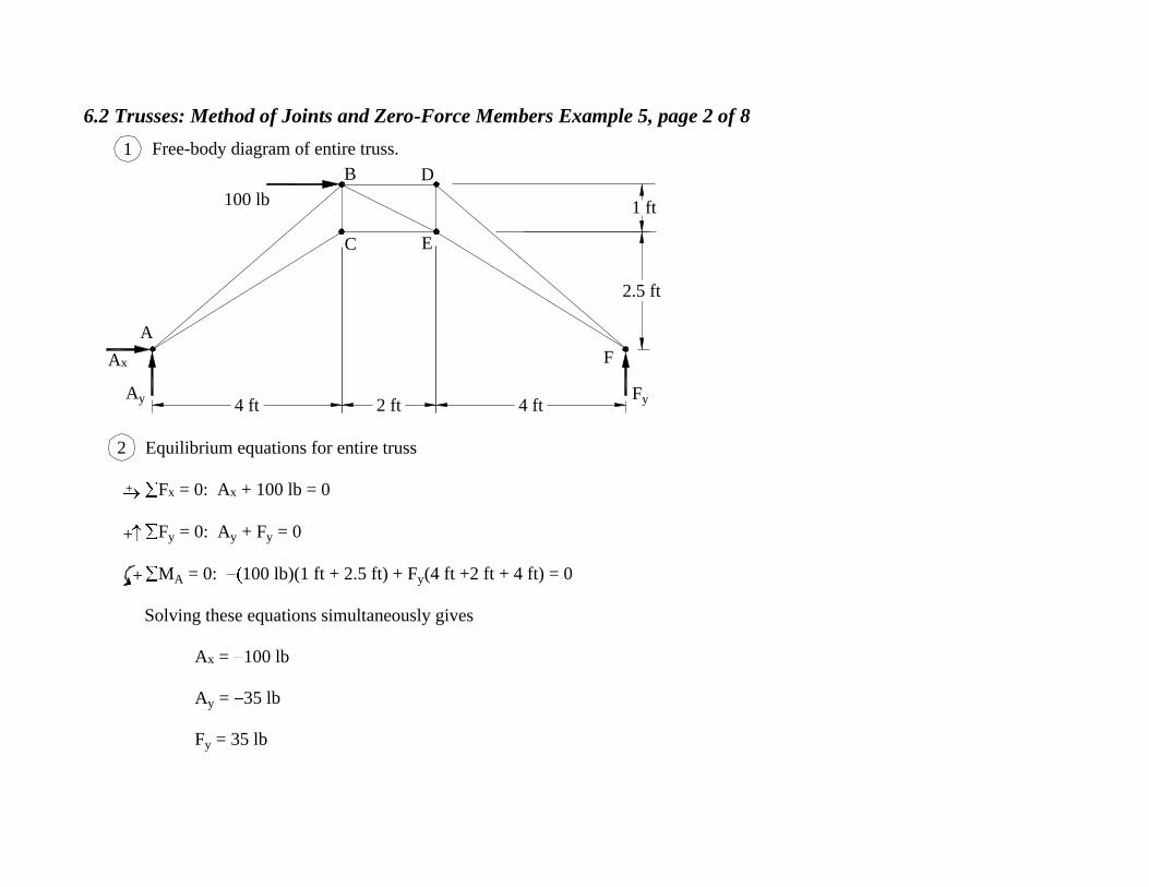
Free-body diagram of entire truss.
Equilibrium equations for entire truss
F x = 0: A
x + 100 lb = 0
F y = 0: A
y + F y = 0
M A = 0: 100 lb)(1 ft + 2.5 ft) + F
y(4 ft +2 ft + 4 ft) = 0
Solving these equations simultaneously gives
A x = 100 lb
A y = 35 lb
F y = 35 lb
F
E
D
C
B
A
100 lb 1 ft
2.5 ft
4 ft2 ft4 ft
Ax
Ay Fy
1
2
+
++

6.2 Trusses: Method of Joints and Zero-Force Members Example 5, page 3 of 8
Free-body diagram
of entire truss.
Only two unknown member
forces act at joint F.A x = 100 lb
F y = 35 lb
Free-body diagram of joint F.
Equilibrium equations for joint F
F x = 0: F
EF cos F DF sin = 0
F y = 0: F
EF sin + F DF cos + 35 lb = 0
Geometry
Solving the equilibrium equations with
= 32.01° and = 48.81° gives
F EF = 165.10 lb (T) Ans.
F DF = 186.03 lb = 186.03 lb (C) Ans.
= tan-1 ( ) = 32.01°
= tan-1 ( ) = 48.81°
Ay = 35 lb
2.5 ft
1 ft100 lb
A
B
C
D
E
F
2 ft4 ft 4 ft
F
F y = 35 lb
FEF
FDF
E
F
4 ft
3.5 ft
2.5 ft
4 ftD
+
+
3
5
6
7
8
4
2.5 ft4 ft
3.5 ft4 ft
6.2 Trusses: Method of Joints and Zero-Force Members Example 5, page 4 of 8
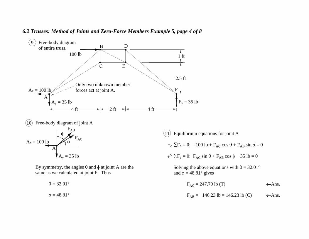
Free-body diagram of joint A
By symmetry, the angles and at joint A are the
same as we calculated at joint F. Thus
= 32.01°
= 48.81°
Equilibrium equations for joint A
F x = 0: 100 lb + F
AC cos + F AB sin = 0
F y = 0: F
AC sin + F AB cos 35 lb = 0
Solving the above equations with = 32.01°
and = 48.81° gives
F AC = 247.70 lb (T) Ans.
F AB = 146.23 lb = 146.23 lb (C) Ans.
A
Ay = 35 lb
A x = 100 lb
+
+
10
11F
AC
F AB
9
4 ft4 ft 2 ft
F
E
D
C
B
A
100 lb 1 ft
2.5 ft
Ay = 35 lb F y = 35 lb
A x = 100 lb
Only two unknown member
forces act at joint A.
Free-body diagram
of entire truss.

6.2 Trusses: Method of Joints and Zero-Force Members Example 5, page 5 of 8
Free-body diagram of entire trussOnly two unknown member
forces act at joint D.
F DF = 186.03 lb (C)
(already known)
Free-body diagram of joint DEquilibrium equations for joint D.
F x = 0: F
BD (186.03 lb) sin 48.81° = 0
F y = 0: F
DE + (186.03 lb) cos 48.81° = 0
Solving these equations gives
F BD = 139.99 lb = 139.99 lb (C) Ans.
F DE = 122.51 lb (T) Ans.
F
EC
A
100 lb
Ay = 35 lb F y = 35 lb
A x = 100 lb
B D
D
48.81°
48.81°
FDE
FBD
F DF = 186.03 lb (C)
13
1415
+
+
12

6.2 Trusses: Method of Joints and Zero-Force Members Example 5, page 6 of 8
Equilibrium equations for joint C.
F x = 0: (247.70 lb) cos 32.01° + F
CE = 0
F y = 0: (247.70 lb) sin 32.01° + F
BC = 0
Solving these equations gives
F CE = 210.04 lb (T) Ans.
F BC = 131.23 lb (T) Ans.
Free-body diagram of joint C.
F AC = 247.70 lb (T)
Only two unknown member
forces act at joint C
F AC = 247.70 lb (T)
(already known)
Free-body diagram of entire truss
A x = 100 lb
F y = 35 lb
Ay = 35 lb
100 lb
A
C E
F17
18 19
C
32.01°
++
FBC
FCE
16
DB

6.2 Trusses: Method of Joints and Zero-Force Members Example 5, page 7 of 8
Free-body diagram of entire truss F DE = 122.51 lb (T)
(already known)
F EF = 165.10 lb (T)
(already known)
F CE = 210.04 lb (T)
(already known)
At joint E, member BE
is the only unknown
member force.
Free-body diagram of joint E.
Equilibrium equation for joint E.
F x = 0: F
BE cos 210.04 lb + (165.10 lb) cos 32.01° = 0
Geometry
Substituting = 26.57° in the equation for joint E
and solving gives
F BE = 78.31 lb = 78.31 lb (C) Ans.
= tan-1 ( ) = 26.57°
A x = 100 lb
F y = 35 lb
Ay = 35 lb
100 lb
A
C E
F
B D
E
32.01°
32.01°
F DE = 122.51 lb (T)
F EF = 165.10 lb (T)
F CE = 210.04 lb (T)
FBE
C E
B
2 ft
1 ft
21
22
23
24
25
+
20
2 ft1 ft

6.2 Trusses: Method of Joints and Zero-Force Members Example 5, page 8 of 8
3535
100
100
A
B
C
D
E
F
140 (C)
210 (T)
123 (T)
186 (C)
165 (T)
131 (T)
146
(C)
248 (T)
78 (C)
Answer diagram
All forces in lb
26

6.2 Trusses: Method of Joints and Zero-Force Members Example 6, page 1 of 9
6. Determine the force in each member of the truss and state
whether the force is tension or compression.
2 kip
A
B C D E F
G
H
I
J
K
L
16 ft 16 ft
14 ft

6.2 Trusses: Method of Joints and Zero-Force Members Example 6, page 2 of 9
Free-body diagram of entire trussEquilibrium equations for entire truss
F x = 0: A
x = 0
F y = 0: A
y + G y 2 kip = 0
M A = 0: 2 kip(16 ft) + G
y(16 ft + 16 ft) = 0
Solving simultaneously gives
A x = 0
A y = 1 kip
G y = 1 kip.
L
K
J
I
H
G
FEDCB
A
2 kip
12
+
+
+
14 ft
16 ft 16 ft
Ax
Ay
Gy

6.2 Trusses: Method of Joints and Zero-Force Members Example 6, page 3 of 9
Free-body
diagram of joint G
Only two unknown member
forces act at joint G.
Equilibrium equations for joint G
F x = 0: F
FG FGL cos = 0
F y = 0: FGL sin + 1 kip = 0
Solving simultaneously gives
F FG = 1.143 kip (T) Ans.
FGL = 1.518 kip = 1.518 kip (C) Ans.
= tan-1 ( ) = 41.19°
Geometry
G y = 1 kip
FGL
F FG
A y = 1 kip
2 kip
A G
H
I
J
K
L
16 ft16 ft
D
J
G
G y = 1 kip
G
14 ft
16 ft
4 3
5
6
7
+
+
B C D E F
14 ft
14 ft16 ft

6.2 Trusses: Method of Joints and Zero-Force Members Example 6, page 4 of 9
16 ft 16 ft
LH
GA
A y = 1 kip G
y = 1 kip
K
J
I
2 kip
14 ft
At joint F, no external forces
act, three members meet, and
two of these members are
collinear. So FL is a
zero-force member, as will
now be shown.
Free-body diagram of joint F
F FG = 1.143 kip
(already known)
Equilibrium equation for joint F
F y = 0: FFL sin = 0
Since sin 0, it follows that
FFL = 0 Ans.F
FFL
FEF
8
109
+
B C D E F

6.2 Trusses: Method of Joints and Zero-Force Members Example 6, page 5 of 9
14 ft
2 kip
I
J
K
A y = 1 kip
A G
HL
16 ft16 ft
At joint L, no external forces act, three
members meet, and two of these
members are collinear. So EL is a
zero-force member:
FEL = 0 Ans.
Member LF has been omitted
because it is a zero-force member.
12
11
B C D E F
G y = 1 kip

6.2 Trusses: Method of Joints and Zero-Force Members Example 6, page 6 of 9
16 ft 16 ft
LH
GA
A y = 1 kip
K
J
I
2 kip
14 ft
Consideration of joint E shows that EK is a zero-force member:
FEK = 0 Ans.
But then consideration of joint K shows that DK is also a
zero-force member:
FDK = 0 Ans.
Members EL and FL have been omitted
because they are zero-force members.14 13
B C D E F
G y = 1 kip

6.2 Trusses: Method of Joints and Zero-Force Members Example 6, page 7 of 9
Because of symmetry, the members in
the left half of the truss must also be
zero-force and so can be omitted, too.
Consideration of joint D shows that DJ
must be a zero-force member:
F DJ = 0 Ans.
All zero-force members in the right
half of the truss have been omitted.
You cannot conclude that member
DJ is a zero-force member by
looking at end J. (Instead, look at
end D.)
LH
GA
A y = 1 kip
K
J
I
2 kip
16 18
15
17
B C D E F
G y = 1 kip

6.2 Trusses: Method of Joints and Zero-Force Members Example 6, page 8 of 9
Free-body diagram of joint L
We have previously shown that
FGL = 1.518 kip (C) Ans.
Consideration of free-body diagrams of K and L
show that
FKL = FKJ = 1.518 kip (C) Ans.
We have previously shown that
F FG = 1.143 kip (T) Ans.
Consideration of free-body diagrams of all joints in the lower
chord, B, C, D, E, and F, shows that all member forces there
must equal 1.143 kip (T).
Zero-force member DJ
has been omitted.
Free-body diagram joint F
By symmetry,
F AH = 1.518 kip = F
HI = F IJ
Ans
21
202 kip
I
J
K
A y = 1 kip
AG
H L
LFKL
FKL = FGLFGL
23
F
FEF = FFG
22
24
19
B C D E FG
y = 1 kip

6.2 Trusses: Method of Joints and Zero-Force Members Example 6, page 9 of 9
L
K
J
I
H
GA
2
0
00
00
0
0
00
1 1
1.143 (T)
1.518 (C)1.518 (C)
Answer diagram
All forces in kips
25
B FC D E

6.2 Trusses: Method of Joints and Zero-Force Members Example 7, page 1 of 7
7. Determine the force in each member and
state whether the force is tension or
compression.
Equilibrium equations for entire truss
F x = 0: A
x = 0
F y = 0: A
y + C y 4 kN = 0
M A = 0: ( 4 kN)(2 m) + C
y(2 m + 2 m) = 0
Solving simultaneously gives
A x = 0, A
y = 2 kN, and C y = 2 kN.
4 kN
AB
C
D E F G
H I J
2 m 2 m
60°
60°
JIH
GFED
CBA
4 kNFree-body diagram
of entire truss
1
2
Ax
AyCy
+
++
2 m2 m

6.2 Trusses: Method of Joints and Zero-Force Members Example 7, page 2 of 7
Cy = 2 kNAy = 2 kN
Ax
4 kN
A BC
D E F G
H I J
60°
Free-body diagram of entire truss. Two members meet at joint J, they are not collinear,
and no external force acts at the joint, so members IJ
and FJ must be zero-force members.
Free-body diagram of joint J
Equilibrium equations for joint J
F x = 0: F
IJ F FJ cos 60° = 0
F y = 0: F
FJ sin 60° = 0
Solving simultaneously gives
F IJ = 0 Ans.
F FJ = 0 Ans.
J
60°
3 4
5
FFJ
FIJ
+
+

6.2 Trusses: Method of Joints and Zero-Force Members Example 7, page 3 of 7
Two members meet at the joint, they are not
collinear, and no external forces act, so the
members carry zero force.
Members IJ and FJ have been omitted
because they are zero-force members.
The same argument at G shows FG and
CG are zero-force members.
Cy = 2 kNAy = 2 kN
Ax
4 kN
A BC
DE F
G
H I J
7 6
8

6.2 Trusses: Method of Joints and Zero-Force Members Example 7, page 4 of 7
All members identified
as zero-force have been
omitted.
Free-body diagram of joint C
Equilibrium equations for joint C
F x = 0: F
BC F CF cos 60° = 0
F y = 0: F
CF sin 60° + 2 kN = 0
Solving simultaneously gives
F CF = 2.309 kN = 2.309 kN (C) Ans.
F BC = 1.155 kN (T) Ans.
By symmetry,
F AE = 2.309 kN (C)
F AB = 1.155 kN (T)
11
I
FE
CB
A
4 kN
Ay = 2 kN
Cy = 2 kN
Cy = 2 kN
C60°
12
10
9
+
+
F BC
F CF

6.2 Trusses: Method of Joints and Zero-Force Members Example 7, page 5 of 7
B
Free-body diagram of joint B
F AB = 1.155 kN (T) F
BC = 1.155 kN (T)
Equilibrium equations for joint B
F x = 0: F
BE cos 60° + F BF cos 60° 1.155 kN + 1.155 kN = 0
F y = 0: F
BE sin 60° + F BF sin 60° = 0
Solving simultaneously gives
FBE = 0 Ans
F BF = 0 Ans.
60° 60°
FBE FBF
14
13+
+
Cy = 2 kN
Ay = 2 kN
4 kN
AB
C
E F
I
F AB = 1.155 kN (T)
(already known)
F BC = 1.155 kN (T)
(already known)

6.2 Trusses: Method of Joints and Zero-Force Members Example 7, page 6 of 7
17
Cy = 2 kNAy = 2 kN
4 kN
AB
C
E F
I
F
y
x
Zero-force members
BE and BF have
been omitted.
At joint F, no external force
acts, three members meet, and
two of these members are
collinear, so member EF is a
zero-force member.
Free-body diagram of joint F
F EF = 0
(zero-force member)
F CF = 2.309 kN (C)
Equilibrium equations for joint F
F y = 0: F
FI + 2.309 kN (C) = 0
Solving gives
F FI = 2.309 kN = 2.309 kN (C) Ans.
Then by symmetry
FEI = FFI = 2.309 kN (C) Ans.
FFI
18
1615
+

6.2 Trusses: Method of Joints and Zero-Force Members Example 7, page 7 of 7
22
4
A BC
D E F G
H I J
Answer diagram
All forces in kN
0 0
0
0 0
0 0
0 0
2.31 (C)
2.31
(C
)
2.31
(C
) 2.31 (C)
1.155 (T) 1.155 (T)
19
