60a0773-a vima user manual - ndssi.com · iv | safety information power cord use the supplied...
TRANSCRIPT
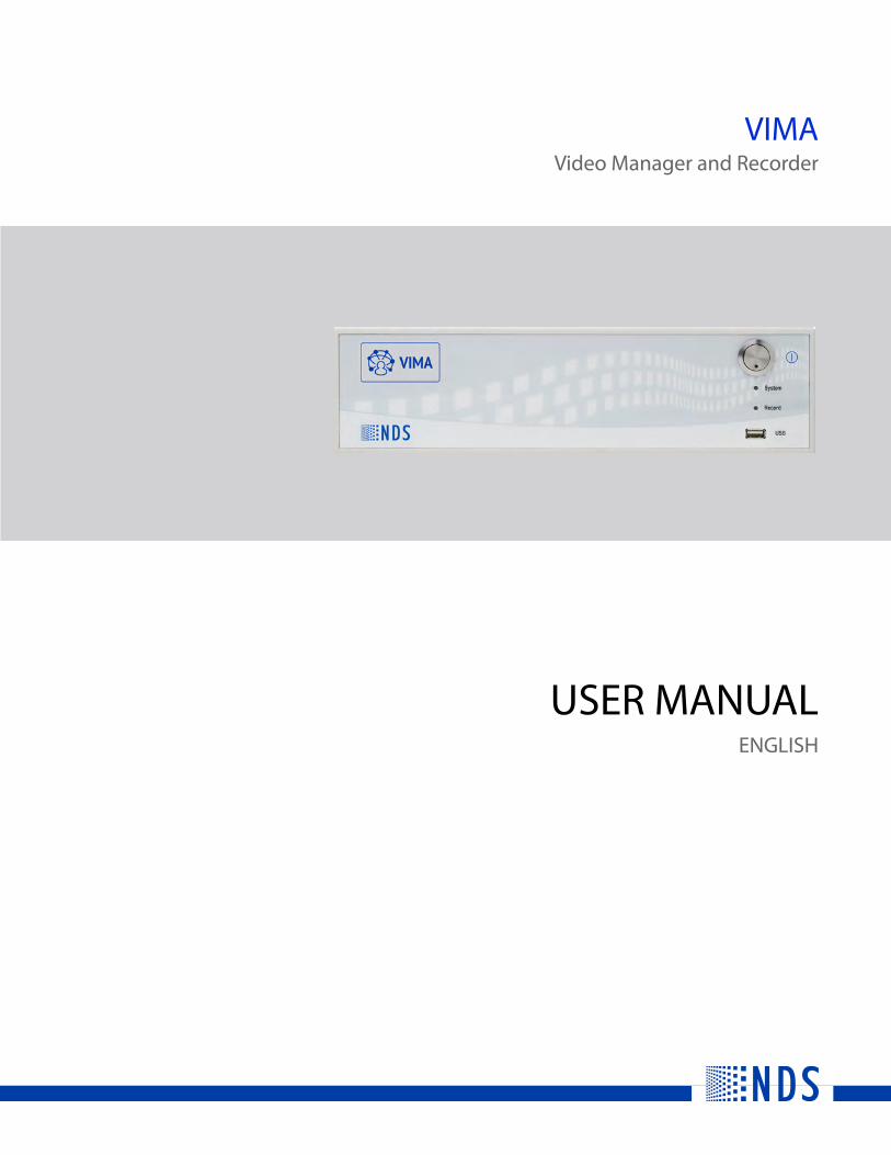
VIMAVideo Manager and Recorder
USER MANUALENGLISH


© 2018 NDS Surgical Imaging, LLC. All rights reserved.
Information in this document has been carefully checked for accuracy; however, no guarantee is given to the correctness of the contents. This document is subject to change without notice. NDS provides this information as reference only. Reference to products from other vendors does not imply any recommendation or endorsement.
This document contains proprietary information protected by copyright. No part of this manual may be reproduced by any mechanical, electronic, or other means, in any form, without prior written permission of NDS.
All trademarks are the property of their respective owners.

Table of Contents
Safety Information . . . . . . . . . . . . . . . . . . . . . . . . . . . . . . . . . . . . . . . . . . . . . . . . . . . . . . . . . . . . . . . . . . . . . . . . . . . . . . . . . .iiiWarnings and Cautions . . . . . . . . . . . . . . . . . . . . . . . . . . . . . . . . . . . . . . . . . . . . . . . . . . . . . . . . . . . . . . . . . . . . . . . . . . .iiiSystem Safety Requirements . . . . . . . . . . . . . . . . . . . . . . . . . . . . . . . . . . . . . . . . . . . . . . . . . . . . . . . . . . . . . . . . . . . . . .iiiPower Requirements. . . . . . . . . . . . . . . . . . . . . . . . . . . . . . . . . . . . . . . . . . . . . . . . . . . . . . . . . . . . . . . . . . . . . . . . . . . . . .iiiRecycling . . . . . . . . . . . . . . . . . . . . . . . . . . . . . . . . . . . . . . . . . . . . . . . . . . . . . . . . . . . . . . . . . . . . . . . . . . . . . . . . . . . . . . . . .iv
Introduction . . . . . . . . . . . . . . . . . . . . . . . . . . . . . . . . . . . . . . . . . . . . . . . . . . . . . . . . . . . . . . . . . . . . . . . . . . . . . . . . . . . . . . . . 1About This Manual. . . . . . . . . . . . . . . . . . . . . . . . . . . . . . . . . . . . . . . . . . . . . . . . . . . . . . . . . . . . . . . . . . . . . . . . . . . . . . . . 1General Information . . . . . . . . . . . . . . . . . . . . . . . . . . . . . . . . . . . . . . . . . . . . . . . . . . . . . . . . . . . . . . . . . . . . . . . . . . . . . . 1Intended Use and Contraindications. . . . . . . . . . . . . . . . . . . . . . . . . . . . . . . . . . . . . . . . . . . . . . . . . . . . . . . . . . . . . . . 1
VIMA Overview and Installation . . . . . . . . . . . . . . . . . . . . . . . . . . . . . . . . . . . . . . . . . . . . . . . . . . . . . . . . . . . . . . . . . . . . . 3Overview . . . . . . . . . . . . . . . . . . . . . . . . . . . . . . . . . . . . . . . . . . . . . . . . . . . . . . . . . . . . . . . . . . . . . . . . . . . . . . . . . . . . . . . . . 3VIMA Models: . . . . . . . . . . . . . . . . . . . . . . . . . . . . . . . . . . . . . . . . . . . . . . . . . . . . . . . . . . . . . . . . . . . . . . . . . . . . . . . . . . . . . 3VIMA Installation . . . . . . . . . . . . . . . . . . . . . . . . . . . . . . . . . . . . . . . . . . . . . . . . . . . . . . . . . . . . . . . . . . . . . . . . . . . . . . . . . 3VIMA Overview . . . . . . . . . . . . . . . . . . . . . . . . . . . . . . . . . . . . . . . . . . . . . . . . . . . . . . . . . . . . . . . . . . . . . . . . . . . . . . . . . . . 4VIMA Control Options. . . . . . . . . . . . . . . . . . . . . . . . . . . . . . . . . . . . . . . . . . . . . . . . . . . . . . . . . . . . . . . . . . . . . . . . . . . . . 9Powering on VIMA . . . . . . . . . . . . . . . . . . . . . . . . . . . . . . . . . . . . . . . . . . . . . . . . . . . . . . . . . . . . . . . . . . . . . . . . . . . . . . . . 9Fuse Replacement . . . . . . . . . . . . . . . . . . . . . . . . . . . . . . . . . . . . . . . . . . . . . . . . . . . . . . . . . . . . . . . . . . . . . . . . . . . . . . . . 9
VIMA Operation . . . . . . . . . . . . . . . . . . . . . . . . . . . . . . . . . . . . . . . . . . . . . . . . . . . . . . . . . . . . . . . . . . . . . . . . . . . . . . . . . . . . 11VIMA Models . . . . . . . . . . . . . . . . . . . . . . . . . . . . . . . . . . . . . . . . . . . . . . . . . . . . . . . . . . . . . . . . . . . . . . . . . . . . . . . . . . . . 12Navigation . . . . . . . . . . . . . . . . . . . . . . . . . . . . . . . . . . . . . . . . . . . . . . . . . . . . . . . . . . . . . . . . . . . . . . . . . . . . . . . . . . . . . . 13Video Tab . . . . . . . . . . . . . . . . . . . . . . . . . . . . . . . . . . . . . . . . . . . . . . . . . . . . . . . . . . . . . . . . . . . . . . . . . . . . . . . . . . . . . . . 14Worklist Tab . . . . . . . . . . . . . . . . . . . . . . . . . . . . . . . . . . . . . . . . . . . . . . . . . . . . . . . . . . . . . . . . . . . . . . . . . . . . . . . . . . . . . 20Procedure Tab . . . . . . . . . . . . . . . . . . . . . . . . . . . . . . . . . . . . . . . . . . . . . . . . . . . . . . . . . . . . . . . . . . . . . . . . . . . . . . . . . . . 27Archive Tab. . . . . . . . . . . . . . . . . . . . . . . . . . . . . . . . . . . . . . . . . . . . . . . . . . . . . . . . . . . . . . . . . . . . . . . . . . . . . . . . . . . . . . 35Exporting Data . . . . . . . . . . . . . . . . . . . . . . . . . . . . . . . . . . . . . . . . . . . . . . . . . . . . . . . . . . . . . . . . . . . . . . . . . . . . . . . . . . 38VIMA Settings . . . . . . . . . . . . . . . . . . . . . . . . . . . . . . . . . . . . . . . . . . . . . . . . . . . . . . . . . . . . . . . . . . . . . . . . . . . . . . . . . . . 40Virtual Keyboard. . . . . . . . . . . . . . . . . . . . . . . . . . . . . . . . . . . . . . . . . . . . . . . . . . . . . . . . . . . . . . . . . . . . . . . . . . . . . . . . . 48About Screen . . . . . . . . . . . . . . . . . . . . . . . . . . . . . . . . . . . . . . . . . . . . . . . . . . . . . . . . . . . . . . . . . . . . . . . . . . . . . . . . . . . . 49Storage Space Utilization Warnings . . . . . . . . . . . . . . . . . . . . . . . . . . . . . . . . . . . . . . . . . . . . . . . . . . . . . . . . . . . . . . 50
Maintenance and Cleaning . . . . . . . . . . . . . . . . . . . . . . . . . . . . . . . . . . . . . . . . . . . . . . . . . . . . . . . . . . . . . . . . . . . . . . . . . 51General Instructions . . . . . . . . . . . . . . . . . . . . . . . . . . . . . . . . . . . . . . . . . . . . . . . . . . . . . . . . . . . . . . . . . . . . . . . . . . . . . 51Manual Cleaning and Disinfection . . . . . . . . . . . . . . . . . . . . . . . . . . . . . . . . . . . . . . . . . . . . . . . . . . . . . . . . . . . . . . . . 51Maintenance Requirements . . . . . . . . . . . . . . . . . . . . . . . . . . . . . . . . . . . . . . . . . . . . . . . . . . . . . . . . . . . . . . . . . . . . . . 51Cleaning Instructions . . . . . . . . . . . . . . . . . . . . . . . . . . . . . . . . . . . . . . . . . . . . . . . . . . . . . . . . . . . . . . . . . . . . . . . . . . . . 51Disposal . . . . . . . . . . . . . . . . . . . . . . . . . . . . . . . . . . . . . . . . . . . . . . . . . . . . . . . . . . . . . . . . . . . . . . . . . . . . . . . . . . . . . . . . . 52
Specifications . . . . . . . . . . . . . . . . . . . . . . . . . . . . . . . . . . . . . . . . . . . . . . . . . . . . . . . . . . . . . . . . . . . . . . . . . . . . . . . . . . . . . . 53VIMA Video Manager and Recorder Specifications . . . . . . . . . . . . . . . . . . . . . . . . . . . . . . . . . . . . . . . . . . . . . . . . 53VIMA Video Recorder Specifications . . . . . . . . . . . . . . . . . . . . . . . . . . . . . . . . . . . . . . . . . . . . . . . . . . . . . . . . . . . . . . 54VIMA Video Manager Specifications . . . . . . . . . . . . . . . . . . . . . . . . . . . . . . . . . . . . . . . . . . . . . . . . . . . . . . . . . . . . . . 55Power Consumption . . . . . . . . . . . . . . . . . . . . . . . . . . . . . . . . . . . . . . . . . . . . . . . . . . . . . . . . . . . . . . . . . . . . . . . . . . . . . 56Data Storage Capacity . . . . . . . . . . . . . . . . . . . . . . . . . . . . . . . . . . . . . . . . . . . . . . . . . . . . . . . . . . . . . . . . . . . . . . . . . . . 56Supported Video Recording Resolutions. . . . . . . . . . . . . . . . . . . . . . . . . . . . . . . . . . . . . . . . . . . . . . . . . . . . . . . . . . 57Supported Video Resolutions . . . . . . . . . . . . . . . . . . . . . . . . . . . . . . . . . . . . . . . . . . . . . . . . . . . . . . . . . . . . . . . . . . . . 57Front Panel LED Indicators . . . . . . . . . . . . . . . . . . . . . . . . . . . . . . . . . . . . . . . . . . . . . . . . . . . . . . . . . . . . . . . . . . . . . . . 64Connector Types and Specifications . . . . . . . . . . . . . . . . . . . . . . . . . . . . . . . . . . . . . . . . . . . . . . . . . . . . . . . . . . . . . . 65Control Connectors and Pinouts. . . . . . . . . . . . . . . . . . . . . . . . . . . . . . . . . . . . . . . . . . . . . . . . . . . . . . . . . . . . . . . . . . 67
Electromagnetic Compatibility Tables . . . . . . . . . . . . . . . . . . . . . . . . . . . . . . . . . . . . . . . . . . . . . . . . . . . . . . . . . . . . . . 69Electromagnetic Emissions . . . . . . . . . . . . . . . . . . . . . . . . . . . . . . . . . . . . . . . . . . . . . . . . . . . . . . . . . . . . . . . . . . . . . . 69Recommended Separation Distances . . . . . . . . . . . . . . . . . . . . . . . . . . . . . . . . . . . . . . . . . . . . . . . . . . . . . . . . . . . . 70
Symbol Glossary . . . . . . . . . . . . . . . . . . . . . . . . . . . . . . . . . . . . . . . . . . . . . . . . . . . . . . . . . . . . . . . . . . . . . . . . . . . . . . . . . . . 71Terms and Conditions . . . . . . . . . . . . . . . . . . . . . . . . . . . . . . . . . . . . . . . . . . . . . . . . . . . . . . . . . . . . . . . . . . . . . . . . . . . . . . 75
Declarations of Conformity. . . . . . . . . . . . . . . . . . . . . . . . . . . . . . . . . . . . . . . . . . . . . . . . . . . . . . . . . . . . . . . . . . . . . . . 75Legal Statement . . . . . . . . . . . . . . . . . . . . . . . . . . . . . . . . . . . . . . . . . . . . . . . . . . . . . . . . . . . . . . . . . . . . . . . . . . . . . . . . . 75
| i

ii |
Safety Information
Warnings and CautionsThis symbol alerts the user that important information regarding the installation and/or operation ofthis equipment follows. Information preceded by this symbol should be read carefully in order to avoiddamage to the equipment.This symbol warns the user that un-insulated voltage within the unit may have sufficient magnitude tocause electrical shock. It is dangerous to make contact with any part inside the unit. To reduce the risk ofelectric shock, DO NOT remove cover (or back).Note: There are no user serviceable parts inside. Refer servicing to qualified service personnel.
This symbol cautions the user that important information regarding the operation and/or maintenanceof this equipment has been included. Information preceded by this symbol should be read carefully toavoid damage to the equipment.
This symbol appears next to the Potential Equalization Conductor on the VIMA.
This symbol denotes the manufacturer.
This symbol denotes the manufacturer’s European Community representative.
Safety ComplianceThis product is T.U.V. approved with respect to electric shock, fire and mechanical hazards only inaccordance with CAN/CSA C22.2 No. 60601-1 and ANSI/AAMI ES60601-1.
Safety ComplianceThis product meets the requirements of EN60601-1 so as to conform to the Medical Device Directive93/42/EEC and 2007/47/EC (general safety information).
This product is intended only for use by healthcare professionals in secured and compliant environments. Thehealthcare professionals using this product assume full responsibility for compliance with all applicable laws andregulations, including but not limited to HIPAA and GDPR.
This product is designed to meet medical safety requirements for a patient vicinity device.
This product is a Class I medical device according to M.D.D. in Europe. No modifications are allowed.
This product is intended for continuous operation.
System Safety RequirementsExternal equipment connected to the signal input/output or other connectors of this product for use in a patientenvironment must comply with the requirements of ANSI/AAMI ES/EN/IEC 60601-1 safety standards. A personwho connects such equipment to this product has by definition formed a system, and is responsible forcompliance of that system to the same ANSI/AAMI ES/EN/IEC 60601-1 safety standards.
NDS recommends that VIMA installation be conducted by qualified personnel.
Power Requirements
Model Electrical RatingVIMA Video Manager and Recorder 2 to 4AVIMA Video Manager 2 to 4AVIMA Video Recorder 1.25 to 2.5AAC Input 100 - 240 Volts, 50 to 60 Hz
Safety Information | iii
Power CordUse the supplied hospital grade power cord with the correct plug for your power source.
• The power cord is the only recognized disconnect device for this product. To power off the product,disconnect the power cord from the AC mains.
• The product and other medical equipment should be positioned so that the power cord and connection to ACmains is readily accessible.
• If an extension cord or power strip is needed for connection of this product to AC mains, confirm that thepower cord plug can be securely connected to the cord or power strip.
• This product should be powered from a center tapped circuit when used in the US at voltages over 120 VAC.
GroundingIt is the responsibility of the installer to ensure that the equipment is installed in accordance with applicablehospital, local and national electrical codes.
An equipotentiality post, located on the back of the equipment, may be used for the purpose of bonding theVIMA chassis to other equipment to ensure that all devices are at the same potential. Any such bond must beinstalled in accordance with applicable electrical codes. The equipotentiality (ground) post is shown on page 4.
Data StorageThis product is designed to provide temporary data storage. Completed procedures and all corresponding datashould be exported, or other otherwise transferred, at intervals to prevent VIMA from reaching 75% capacity.
A notification is provided when the storage utilization reaches 75%. When storage utilization reaches 95%, analert is provided and recording and image capture features are blocked.
It is recommended to backup all stored data.
RecyclingFollow local governing ordinances and recycling plans regarding the recycling or disposal of thisproduct.
iv | Safety Information
Introduction
About This ManualThis manual is designed to assist the user with installation, setup and operation of VIMA.
General Information
VIMA Models:• VIMA Video Manager with Recorder• VIMA Video Recorder• VIMA Video Manager
Intended Use and ContraindicationsIntended UseVIMA is a family of three product configurations with the intended use to enable a clinical user to manage imagerouting, the recording of videos, and capturing of images. VIMA will typically support the Operating Room andEndo/GI procedure room environment, and it shall integrate with the hospital electronic medical records (EMR)systems utilizing the DICOM interface standard.
VIMA, as a stand-alone device, shall support multiple digital video input and output standards and allows usersto interconnect them regardless of their individual technologies. From an external touch screen display, VIMAwill interface with the User utilizing a Graphical User Interface (GUI) that shall be appealing and intuitive to useby the User.
Contraindications1. Do not use this product in the presence of flammable anesthetics mixture with air, oxygen or nitrous oxide.
2. To prevent fire or shock hazards, do not expose this product to rain or moisture.
3. No part of this product may come in contact with a patient. Never touch the product and a patient at thesame time.
4. For mission critical applications, we strongly recommend that a replacement unit be immediately available.
Introduction | 1

2 | Introduction
VIMA Overview and Installation
OverviewVIMA is a family of three product configurations that enable a clinical user to manage video and image routing,the recording of videos, and capturing of images. VIMA is used in the Operating Room and Endo/GI procedureroom environment, and it integrates with the hospital electronic medical records (EMR) systems utilizing theDICOM interface standard.VIMA, as a stand-alone device, supports multiple digital input and output standards. When used in combinationwith ScaleOR, various legacy analog input signals can also be supported. VIMA is controlled from an externaltouch screen display via an intuitive graphical user interface.
VIMA Models:• VIMA Video Manager with Recorder• VIMA Video Recorder• VIMA Video Manager
VIMA Installation• Place the unit on a flat surface. • Stacking of the VIMA device on another device is allowed.• Leave a space of at least 5 cm from other devices on the left-side, right-side, and rear of VIMA.
Leave a space of at least 5 cm from other devices on the left-side, right-side, and rear of VIMA,especially high-frequency surgical equipment. WARNING: Use of this equipment adjacent to or stacked with other equipment should be avoidedbecause it could result in improper operation. If such use is necessary, this equipment and the otherequipment should be observed to verify that they are operating normally.
Connection Procedure1. Connect the video source to video input (HDMI, 3G-SDI, or HDBaseT).2. Connect the target device to output video signals (HDMI or HDBaseT).3. Connect the control display to one of the display ports (DP++ or HDMI 1 Touch).4. Connect the required accessories (touchscreen, keyboard, mouse, etc.) to the USB ports.5. Connect the power source as indicated below.
Power SupplyThe power supply voltage must match the voltage indicated on the label.• Connect the power cable into the facility power outlet.• Connect the power cable into VIMA receptacle. • Connect the potential equalization plug into connection for potential equalization on VIMA.• Connect the cable for the potential equalization to the facility.
Connecting AccessoriesWARNING: Combinations of accessories that are not listed in the instruction manual may only be used if they areintended exclusively for a given use and do not affect the performance, safety, and EMC characteristics of VIMA.WARNING: Portable RF communications equipment (including peripherals such as antenna cables and externalantennas) should be used no closer than 30 cm (12 inches) to any part of the (ME EQUIPMENT or ME SYSTEM),including cables specified by the manufacturer. Otherwise, degradation of the performance of this equipmentcould result.All devices that are connected to the interface must clearly meet the relevant IEC standard (eg. IEC 60950 devicesfor data processing and IEC / EN 60601-1 for medical electrical equipment).All configurations must comply with the system standard IEC / EN 60601-1.When connecting devices to each other, ensure that the configuration and system complies with standard IEC /EN 60601-1 or equivalent national standards. For assistance, please contact your local distributor or manufacturer.
VIMA Overview and Installation | 3
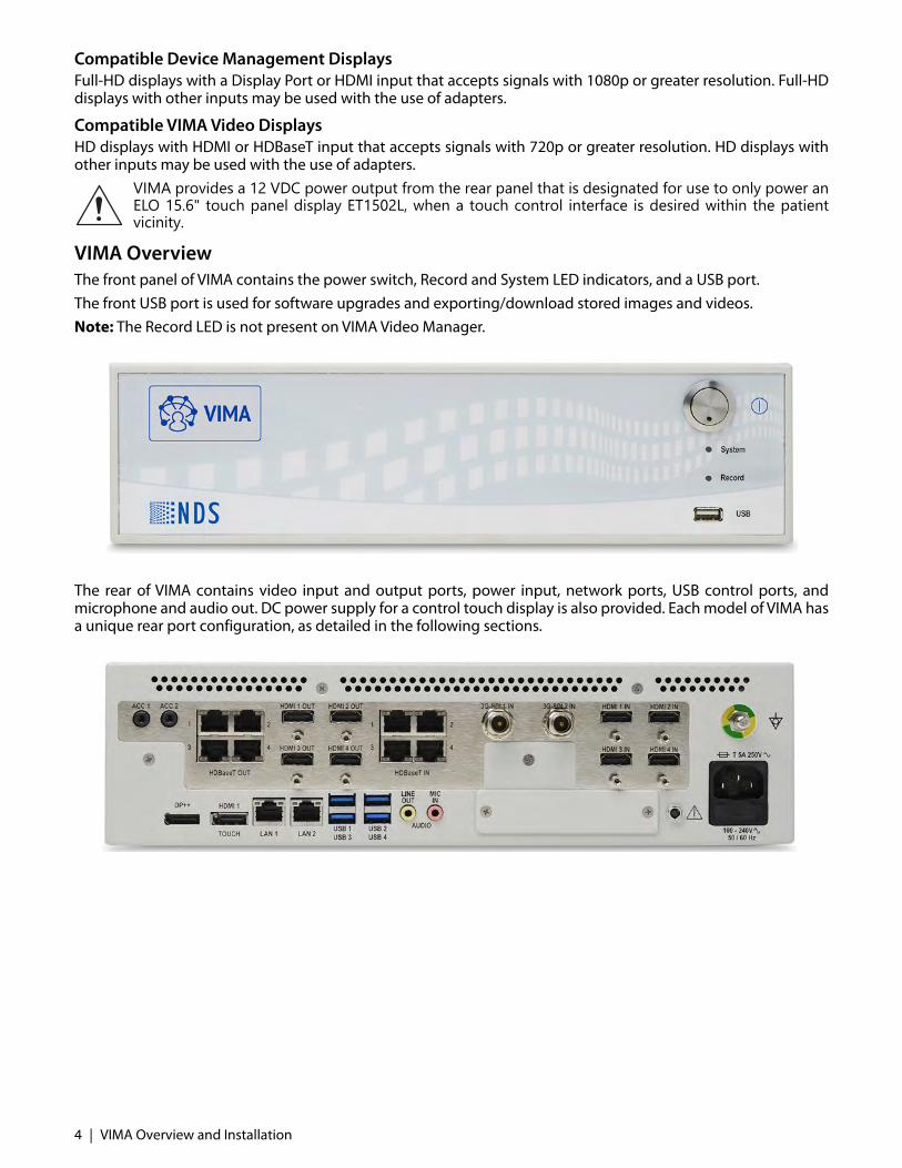
Compatible Device Management DisplaysFull-HD displays with a Display Port or HDMI input that accepts signals with 1080p or greater resolution. Full-HDdisplays with other inputs may be used with the use of adapters.
Compatible VIMA Video DisplaysHD displays with HDMI or HDBaseT input that accepts signals with 720p or greater resolution. HD displays withother inputs may be used with the use of adapters.
VIMA provides a 12 VDC power output from the rear panel that is designated for use to only power anELO 15.6" touch panel display ET1502L, when a touch control interface is desired within the patientvicinity.
VIMA OverviewThe front panel of VIMA contains the power switch, Record and System LED indicators, and a USB port. The front USB port is used for software upgrades and exporting/download stored images and videos. Note: The Record LED is not present on VIMA Video Manager.
The rear of VIMA contains video input and output ports, power input, network ports, USB control ports, andmicrophone and audio out. DC power supply for a control touch display is also provided. Each model of VIMA hasa unique rear port configuration, as detailed in the following sections.
4 | VIMA Overview and Installation

VIMA Video Manager with Recorder
VIMA Video Manager with Recorder has ten video input ports and eight video output ports as detailed in thePorts table below. Two Accessory ports are provided. Audio ports are provided for audio services. VIMA Video Manager with Recorder has eight control ports. A display port (DP++) and an HDMI port (HDMI 1Touch) are provided to connect one or two 1080p touch displays for VIMA GUI. Touch displays require a USBconnection. One LAN port provides network connectivity and four USB ports for monitor touch, externalkeyboard and mouse, or USB devices to export captured images and videos.
Port Type Number of Ports Notes
Accessory Ports
ACC 2 For use with video and still image control devices.ACC 1 is used for image capture trigger. ACC 2 is used for start/stop recording trigger.
USB (Front panel) 1 Connect a USB device to export captured images and videos, or external keyboard. This is USB 2.0.This USB port can be used in combination with the HDMI 1 or DP++ ports for a Touch screen connection, but is not recommended.
Video Output Ports
HDBaseT Out 4 PoE feature is available only on HDBaseT Out 1 and HDBaseT Out 2. PoE is not available on ports 3 and 4. PoE (15 Watts) will be provided. (802.3at Type 2 Class 3)
HDMI Out 4
Video Input Ports
HDBaseT In 4 PoE (30 Watts) will be provided. (802.3at Type 2 Class 4)
3G-SDI In 2
HDMI In 4
Audio
Line Out 1
Mic In 1
Management and Control Ports
DP++ 1 Only accepts a Display Port connector. Will automatically detect DP or HDMI signal.
HDMI 1 Touch 1 Accepts both DP and HDMI connector. Will only support an HDMI signal.
LAN 2 Only LAN 1 is active. LAN 2 is an inactive port and the control indicators do not work.
USB 4 Connect a USB device to export captured images and videos, or external keyboard to any of the USB ports. Any of the four USB ports can be used in combination with the HDMI 1 or DP++ ports for a Touch screen connection.These are USB 3.0.
Other Ports
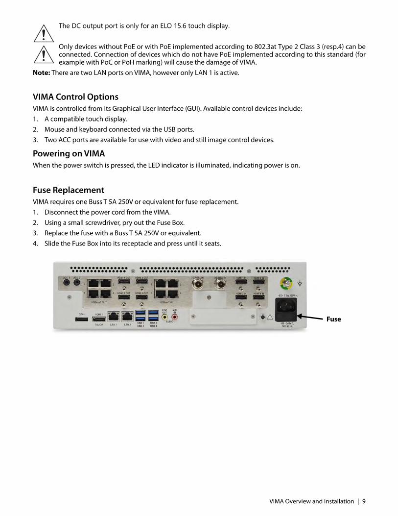
DC output 1 The DC output port is only for an ELO 15.6 touch display.
VIMA Overview and Installation | 5

The DC output port is only for an ELO 15.6 touch display.
Only devices without PoE or with PoE implemented according to 802.3at Type 2 Class 3 (resp.4) can beconnected. Connection of devices which do not have PoE implemented according to this standard (forexample with PoC or PoH marking) will cause the damage of VIMA.
Note: There are two LAN ports on VIMA, however only LAN 1 is active.
6 | VIMA Overview and Installation

VIMA Video Recorder
VIMA Video Recorder has three video input ports and no video output ports as detailed in the Ports table below.Two Accessory ports are provided for camera remote controls. Audio ports are provided for audio services. VIMA Video Recorder has seven control ports. A display port (DP++) and an HDMI port (HDMI 1 Touch) areprovided to connect one or two 1080p touch displays for VIMA GUI. One LAN port provides network connectivityand four USB ports for control devices (keyboard and mouse) and accessories.
The DC output port is only for an ELO 15.6 touch display.
Only devices without PoE or with PoE implemented according to 802.3at Type 2 Class 3 (resp.4) can beconnected. Connection of devices which do not have PoE implemented according to this standard (forexample with PoC or PoH marking) will cause the damage of VIMA.
Note: There are two LAN ports on VIMA, however only LAN 1 is active.
Port Type Number of Ports Notes
Accessory Ports
ACC 2 For use with video and still image control devices. ACC 1 is used for image capture trigger. ACC 2 is used for start/stop recording trigger.
USB (Front panel) 1 Connect a USB device to export captured images and videos, or external keyboard. This is USB 2.0.This USB port can be used in combination with the HDMI 1 or DP++ ports for a Touch screen connection, but is not recommended.
Video Input Ports
HDBaseT In 1 PoE (30 Watts) will be provided. (802.3at Type 2 Class 4)
3G-SDI In 1
DVI-D 1
Audio
Line Out 1
Mic In 1
Management and Control Ports
DP++ 1 Only accepts a Display Port connector. Will automatically detect DP or HDMI signal.
HDMI 1 Touch 1 Accepts both DP and HDMI connector. Will only accept an HDMI signal.
LAN 2 Only LAN 1 is active. LAN 2 is an inactive port and the control indicators do not work.
USB 4 Connect a USB device to export captured images and videos, or external keyboard to any of the USB ports. Any of the four USB ports can be used in combination with the HDMI 1 or DP++ ports for a Touch screen connection.These are USB 3.0.
Other Ports
DC output 1 The DC output port is only for an ELO 15.6 touch display.
VIMA Overview and Installation | 7
VIMA Video Manager
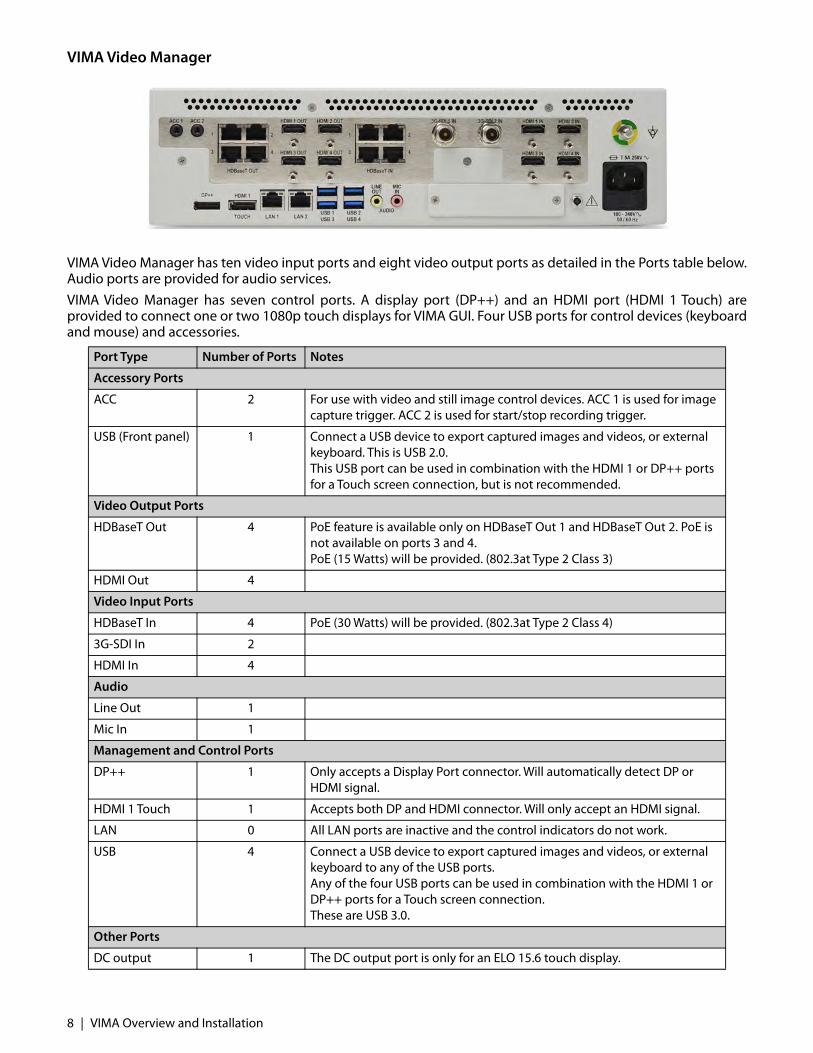
VIMA Video Manager has ten video input ports and eight video output ports as detailed in the Ports table below.Audio ports are provided for audio services. VIMA Video Manager has seven control ports. A display port (DP++) and an HDMI port (HDMI 1 Touch) areprovided to connect one or two 1080p touch displays for VIMA GUI. Four USB ports for control devices (keyboardand mouse) and accessories.
Port Type Number of Ports Notes
Accessory Ports
ACC 2 For use with video and still image control devices. ACC 1 is used for image capture trigger. ACC 2 is used for start/stop recording trigger.
USB (Front panel) 1 Connect a USB device to export captured images and videos, or external keyboard. This is USB 2.0.This USB port can be used in combination with the HDMI 1 or DP++ ports for a Touch screen connection, but is not recommended.
Video Output Ports
HDBaseT Out 4 PoE feature is available only on HDBaseT Out 1 and HDBaseT Out 2. PoE is not available on ports 3 and 4. PoE (15 Watts) will be provided. (802.3at Type 2 Class 3)
HDMI Out 4
Video Input Ports
HDBaseT In 4 PoE (30 Watts) will be provided. (802.3at Type 2 Class 4)
3G-SDI In 2
HDMI In 4
Audio
Line Out 1
Mic In 1
Management and Control Ports
DP++ 1 Only accepts a Display Port connector. Will automatically detect DP or HDMI signal.
HDMI 1 Touch 1 Accepts both DP and HDMI connector. Will only accept an HDMI signal.
LAN 0 All LAN ports are inactive and the control indicators do not work.
USB 4 Connect a USB device to export captured images and videos, or external keyboard to any of the USB ports. Any of the four USB ports can be used in combination with the HDMI 1 or DP++ ports for a Touch screen connection.These are USB 3.0.
Other Ports
DC output 1 The DC output port is only for an ELO 15.6 touch display.
8 | VIMA Overview and Installation
The DC output port is only for an ELO 15.6 touch display.
Only devices without PoE or with PoE implemented according to 802.3at Type 2 Class 3 (resp.4) can beconnected. Connection of devices which do not have PoE implemented according to this standard (forexample with PoC or PoH marking) will cause the damage of VIMA.
Note: There are two LAN ports on VIMA, however only LAN 1 is active.
VIMA Control OptionsVIMA is controlled from its Graphical User Interface (GUI). Available control devices include: 1. A compatible touch display.2. Mouse and keyboard connected via the USB ports. 3. Two ACC ports are available for use with video and still image control devices.
Powering on VIMA When the power switch is pressed, the LED indicator is illuminated, indicating power is on.
Fuse ReplacementVIMA requires one Buss T 5A 250V or equivalent for fuse replacement. 1. Disconnect the power cord from the VIMA.2. Using a small screwdriver, pry out the Fuse Box.3. Replace the fuse with a Buss T 5A 250V or equivalent.4. Slide the Fuse Box into its receptacle and press until it seats.
Fuse
VIMA Overview and Installation | 9

10 | VIMA Overview and Installation
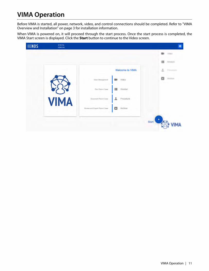
VIMA OperationBefore VIMA is started, all power, network, video, and control connections should be completed. Refer to "VIMAOverview and Installation" on page 3 for installation information.
When VIMA is powered on, it will proceed through the start process. Once the start process is completed, theVIMA Start screen is displayed. Click the Start button to continue to the Video screen.
VIMA Operation | 11
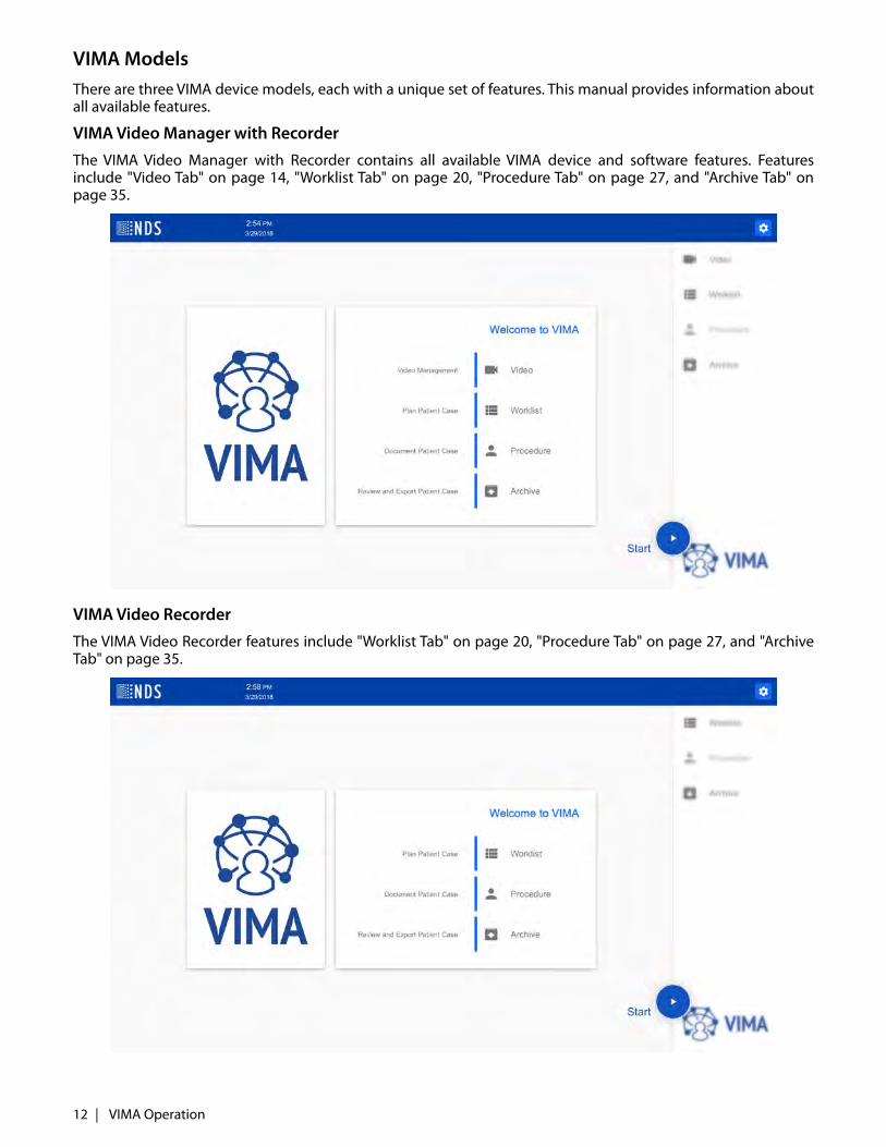
VIMA ModelsThere are three VIMA device models, each with a unique set of features. This manual provides information aboutall available features.
VIMA Video Manager with RecorderThe VIMA Video Manager with Recorder contains all available VIMA device and software features. Featuresinclude "Video Tab" on page 14, "Worklist Tab" on page 20, "Procedure Tab" on page 27, and "Archive Tab" onpage 35.
VIMA Video RecorderThe VIMA Video Recorder features include "Worklist Tab" on page 20, "Procedure Tab" on page 27, and "ArchiveTab" on page 35.
12 | VIMA Operation
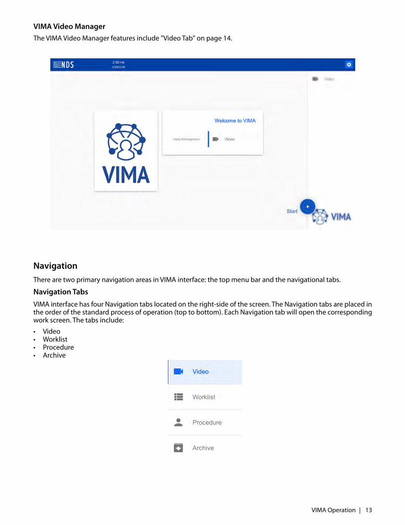
VIMA Video ManagerThe VIMA Video Manager features include "Video Tab" on page 14.
NavigationThere are two primary navigation areas in VIMA interface: the top menu bar and the navigational tabs.
Navigation Tabs
VIMA interface has four Navigation tabs located on the right-side of the screen. The Navigation tabs are placed inthe order of the standard process of operation (top to bottom). Each Navigation tab will open the correspondingwork screen. The tabs include:
• Video • Worklist• Procedure• Archive
VIMA Operation | 13

Video TabThe Video tab opens the Video Management screen, as shown below.
• Input interface - All video inputs (active and inactive) are listed. A blue camera icon indicates active inputs. A gray camera icon indicates an inactive video input.
• Output interface - An overview of all video outputs. A blue monitor icon indicates active outputs. A gray monitor icon indicates an inactive video output.
Using the Video Management screen, select an input (video source) to be displayed on an output (video display).Using the Video Management screen, any input can be directed to display on any output by either drag anddrop, or click on an input followed by a click on an output. Any input can be directed to any or all output displays.
About the Video Management ScreenThe Inputs section can be filtered using any of three options: All Inputs, Active Inputs, or Inactive Inputs.
Configuring Displayed Names for Inputs and Outputs
The default configuration contains generic names for inputs and outputs. Refer to "Video Management Settings"on page 41 for instruction to configure the names of inputs and outputs.
14 | VIMA Operation

Filtering Inputs and Outputs
The inputs (video source) and outputs (displays) can be filtered.
1. Select the Inputs menu to view All Inputs, Active Inputs, or Inactive Inputs. An active input is indicated with ablue video icon. An inactive input is indicated with a gray video icon.
2. Select the Outputs menu to view All Outputs, Active Outputs, or Inactive Outputs. An active output isindicated with a blue video icon. An inactive output is indicated with a gray video icon.
VIMA Operation | 15
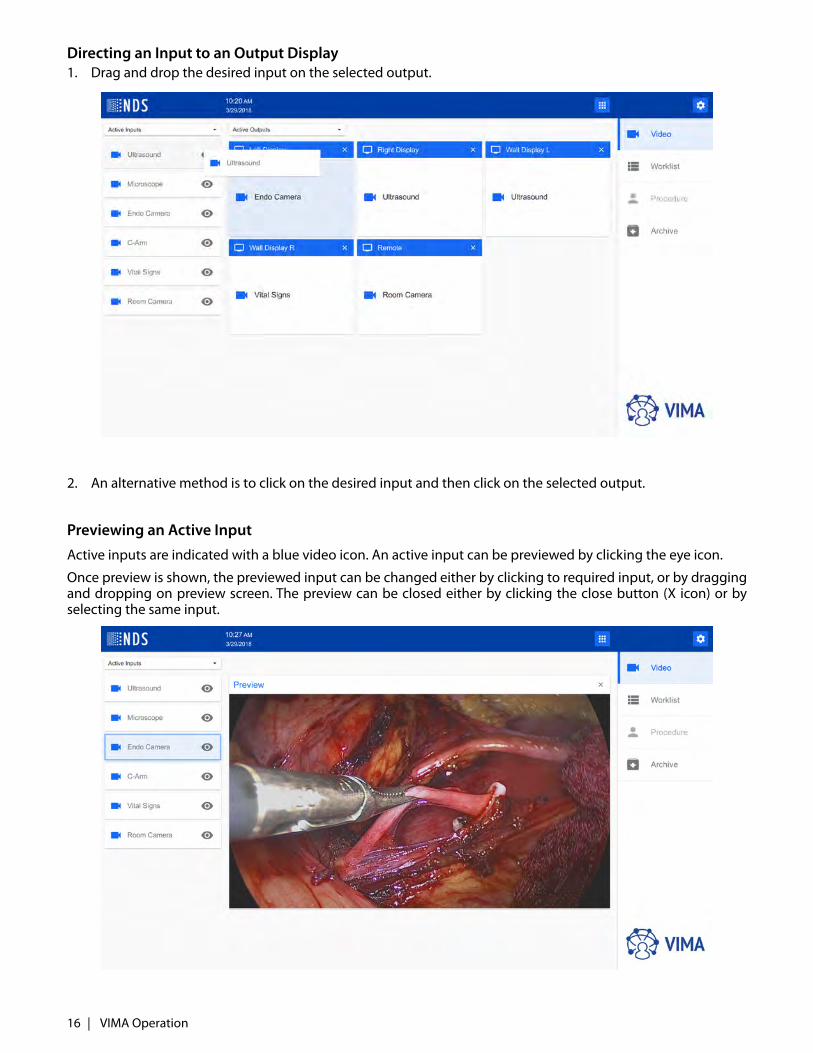
Directing an Input to an Output Display1. Drag and drop the desired input on the selected output.
2. An alternative method is to click on the desired input and then click on the selected output.
Previewing an Active Input
Active inputs are indicated with a blue video icon. An active input can be previewed by clicking the eye icon.
Once preview is shown, the previewed input can be changed either by clicking to required input, or by draggingand dropping on preview screen. The preview can be closed either by clicking the close button (X icon) or byselecting the same input.
16 | VIMA Operation
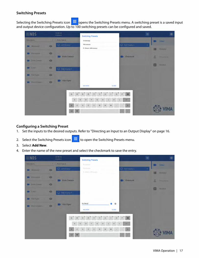
Switching Presets
Selecting the Switching Presets icon opens the Switching Presets menu. A switching preset is a saved inputand output device configuration. Up to 100 switching presets can be configured and saved.
Configuring a Switching Preset1. Set the inputs to the desired outputs. Refer to "Directing an Input to an Output Display" on page 16.
2. Select the Switching Presets icon to open the Switching Presets menu.
3. Select Add New. 4. Enter the name of the new preset and select the checkmark to save the entry.
VIMA Operation | 17
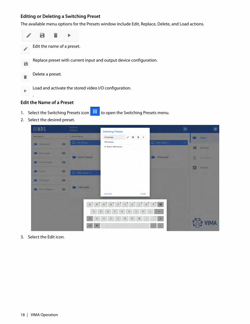
Editing or Deleting a Switching Preset
The available menu options for the Presets window include Edit, Replace, Delete, and Load actions.
Edit the name of a preset.
Replace preset with current input and output device configuration.
Delete a preset.
Load and activate the stored video I/O configuration.
.
Edit the Name of a Preset
1. Select the Switching Presets icon to open the Switching Presets menu.
2. Select the desired preset.
3. Select the Edit icon.
18 | VIMA Operation

4. Edit the name of the preset, as desired.
5. Select the checkmark to save the new name of the preset.6. Select Close to close the Switching Presets window.
VIMA Operation | 19
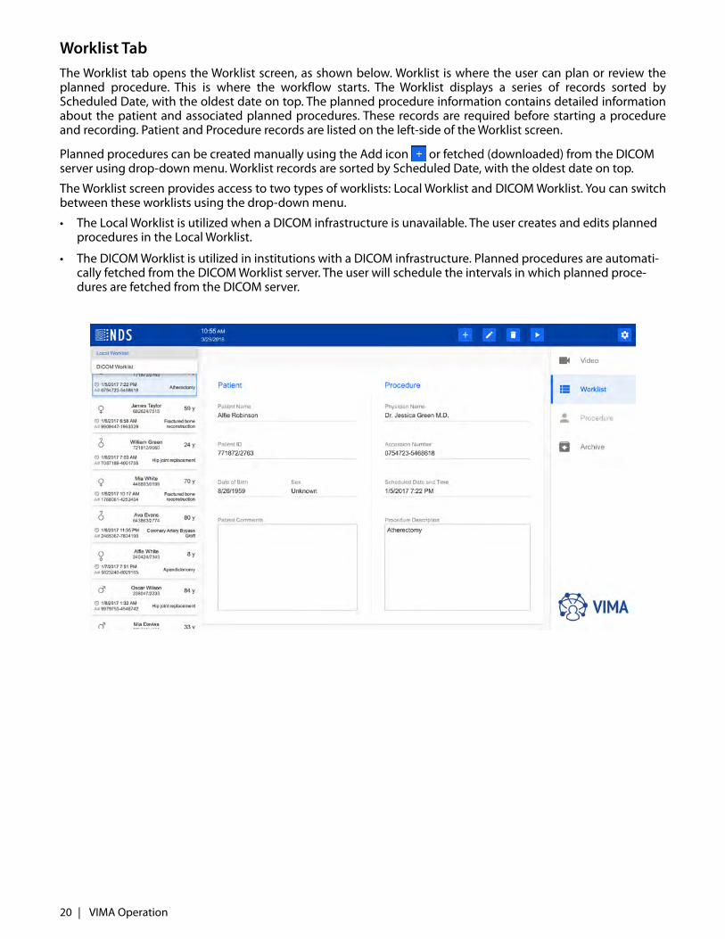
Worklist TabThe Worklist tab opens the Worklist screen, as shown below. Worklist is where the user can plan or review theplanned procedure. This is where the workflow starts. The Worklist displays a series of records sorted byScheduled Date, with the oldest date on top. The planned procedure information contains detailed informationabout the patient and associated planned procedures. These records are required before starting a procedureand recording. Patient and Procedure records are listed on the left-side of the Worklist screen.
Planned procedures can be created manually using the Add icon or fetched (downloaded) from the DICOM server using drop-down menu. Worklist records are sorted by Scheduled Date, with the oldest date on top.
The Worklist screen provides access to two types of worklists: Local Worklist and DICOM Worklist. You can switchbetween these worklists using the drop-down menu.
• The Local Worklist is utilized when a DICOM infrastructure is unavailable. The user creates and edits planned procedures in the Local Worklist.
• The DICOM Worklist is utilized in institutions with a DICOM infrastructure. Planned procedures are automati-cally fetched from the DICOM Worklist server. The user will schedule the intervals in which planned proce-dures are fetched from the DICOM server.
20 | VIMA Operation
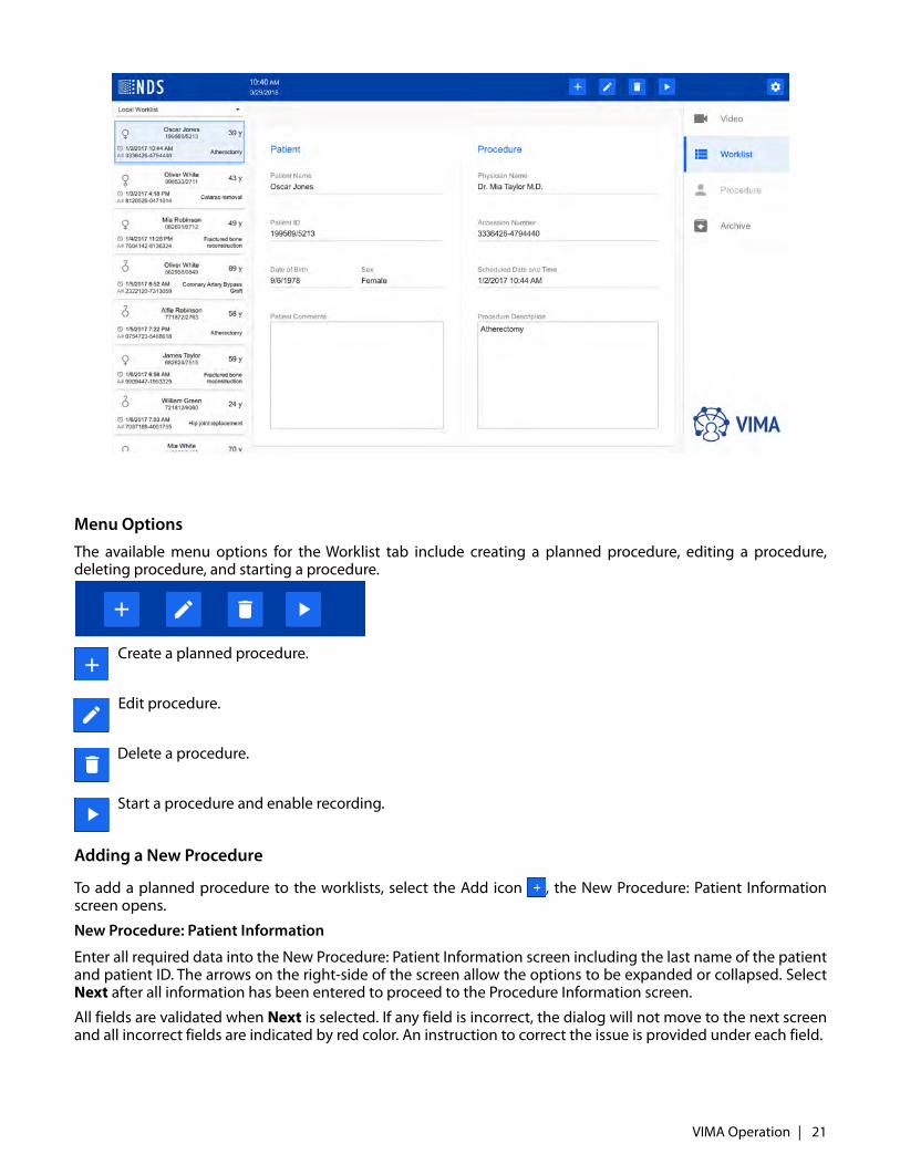
Menu Options
The available menu options for the Worklist tab include creating a planned procedure, editing a procedure,deleting procedure, and starting a procedure.
Create a planned procedure.
Edit procedure.
Delete a procedure.
Start a procedure and enable recording.
Adding a New Procedure
To add a planned procedure to the worklists, select the Add icon , the New Procedure: Patient Informationscreen opens.
New Procedure: Patient Information
Enter all required data into the New Procedure: Patient Information screen including the last name of the patientand patient ID. The arrows on the right-side of the screen allow the options to be expanded or collapsed. SelectNext after all information has been entered to proceed to the Procedure Information screen.
All fields are validated when Next is selected. If any field is incorrect, the dialog will not move to the next screenand all incorrect fields are indicated by red color. An instruction to correct the issue is provided under each field.
VIMA Operation | 21
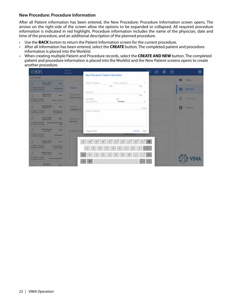
New Procedure: Procedure Information
After all Patient information has been entered, the New Procedure: Procedure Information screen opens. Thearrows on the right-side of the screen allow the options to be expanded or collapsed. All required procedureinformation is indicated in red highlight. Procedure information includes the name of the physician, date andtime of the procedure, and an additional description of the planned procedure.
• Use the BACK button to return the Patient Information screen for the current procedure. • After all information has been entered, select the CREATE button. The completed patient and procedure
information is placed into the Worklist. • When creating multiple Patient and Procedure records, select the CREATE AND NEW button. The completed
patient and procedure information is placed into the Worklist and the New Patient screens opens to create another procedure.
22 | VIMA Operation
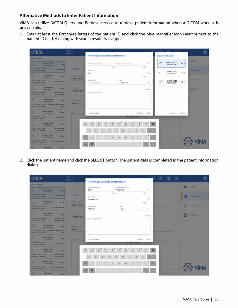
Alternative Methods to Enter Patient Information
VIMA can utilize DICOM Query and Retrieve service to retrieve patient information when a DICOM worklist isunavailable.
1. Enter at least the first three letters of the patient ID and click the blue magnifier icon (search) next to thepatient ID field. A dialog with search results will appear.
2. Click the patient name and click the SELECT button. The patient data is completed in the patient informationdialog.
VIMA Operation | 23
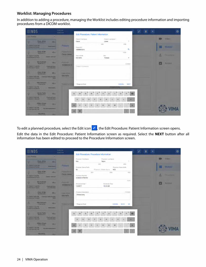
Worklist: Managing Procedures
In addition to adding a procedure, managing the Worklist includes editing procedure information and importingprocedures from a DICOM worklist.
To edit a planned procedure, select the Edit icon , the Edit Procedure: Patient Information screen opens.
Edit the data in the Edit Procedure: Patient Information screen as required. Select the NEXT button after allinformation has been edited to proceed to the Procedure Information screen.
24 | VIMA Operation
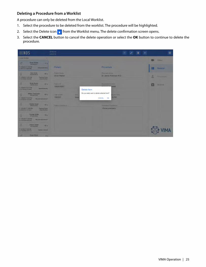
Deleting a Procedure from a Worklist
A procedure can only be deleted from the Local Worklist.
1. Select the procedure to be deleted from the worklist. The procedure will be highlighted.
2. Select the Delete icon from the Worklist menu. The delete confirmation screen opens.
3. Select the CANCEL button to cancel the delete operation or select the OK button to continue to delete theprocedure.
VIMA Operation | 25
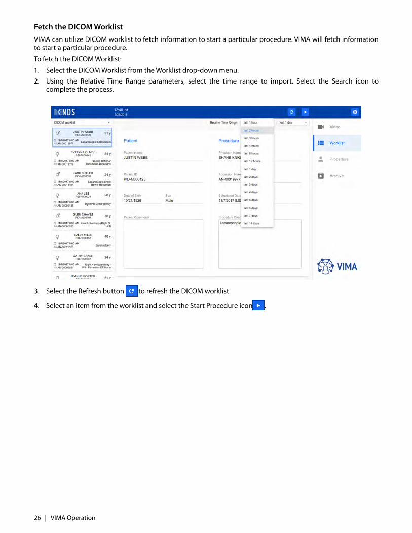
Fetch the DICOM Worklist
VIMA can utilize DICOM worklist to fetch information to start a particular procedure. VIMA will fetch informationto start a particular procedure.
To fetch the DICOM Worklist:
1. Select the DICOM Worklist from the Worklist drop-down menu. 2. Using the Relative Time Range parameters, select the time range to import. Select the Search icon to
complete the process.
3. Select the Refresh button to refresh the DICOM worklist.
4. Select an item from the worklist and select the Start Procedure icon .
26 | VIMA Operation
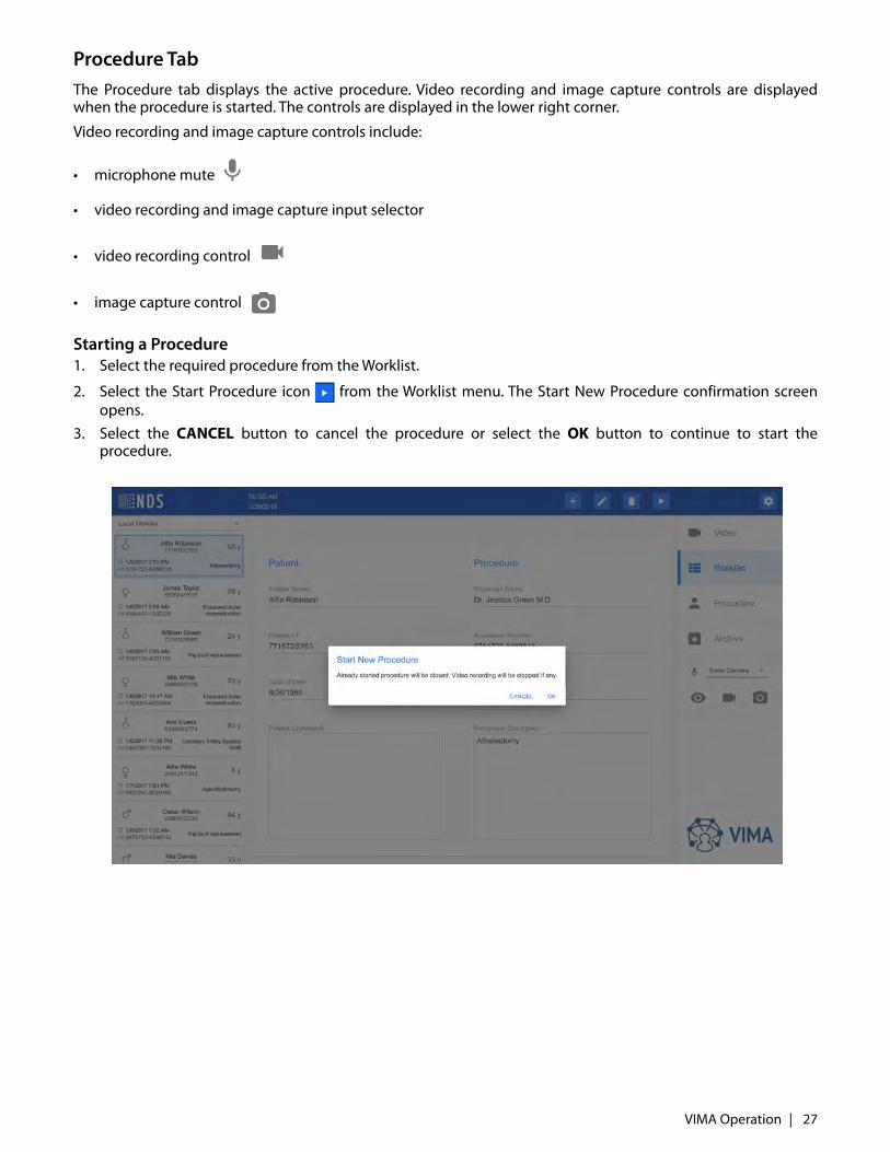
Procedure TabThe Procedure tab displays the active procedure. Video recording and image capture controls are displayedwhen the procedure is started. The controls are displayed in the lower right corner.
Video recording and image capture controls include:
• microphone mute
• video recording and image capture input selector
• video recording control
• image capture control
Starting a Procedure1. Select the required procedure from the Worklist.
2. Select the Start Procedure icon from the Worklist menu. The Start New Procedure confirmation screenopens.
3. Select the CANCEL button to cancel the procedure or select the OK button to continue to start theprocedure.
VIMA Operation | 27
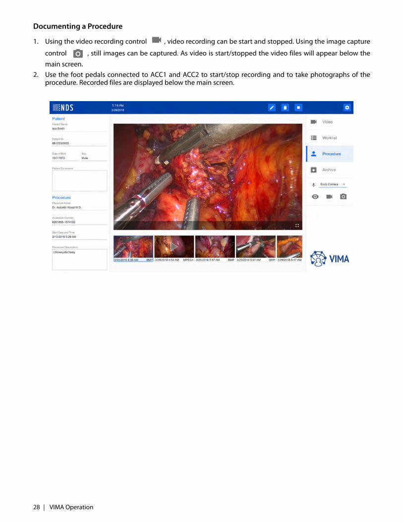
Documenting a Procedure
1. Using the video recording control , video recording can be start and stopped. Using the image capture
control , still images can be captured. As video is start/stopped the video files will appear below the
main screen.2. Use the foot pedals connected to ACC1 and ACC2 to start/stop recording and to take photographs of the
procedure. Recorded files are displayed below the main screen.
28 | VIMA Operation
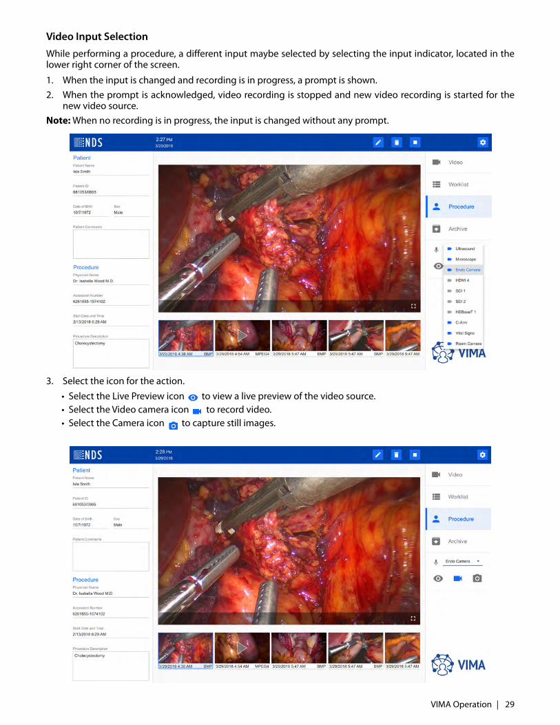
Video Input Selection
While performing a procedure, a different input maybe selected by selecting the input indicator, located in thelower right corner of the screen.
1. When the input is changed and recording is in progress, a prompt is shown.2. When the prompt is acknowledged, video recording is stopped and new video recording is started for the
new video source.Note: When no recording is in progress, the input is changed without any prompt.
3. Select the icon for the action.
• Select the Live Preview icon to view a live preview of the video source. • Select the Video camera icon to record video. • Select the Camera icon to capture still images.
VIMA Operation | 29
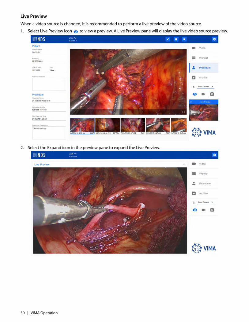
Live Preview
When a video source is changed, it is recommended to perform a live preview of the video source.
1. Select Live Preview icon to view a preview. A Live Preview pane will display the live video source preview.
2. Select the Expand icon in the preview pane to expand the Live Preview.
30 | VIMA Operation
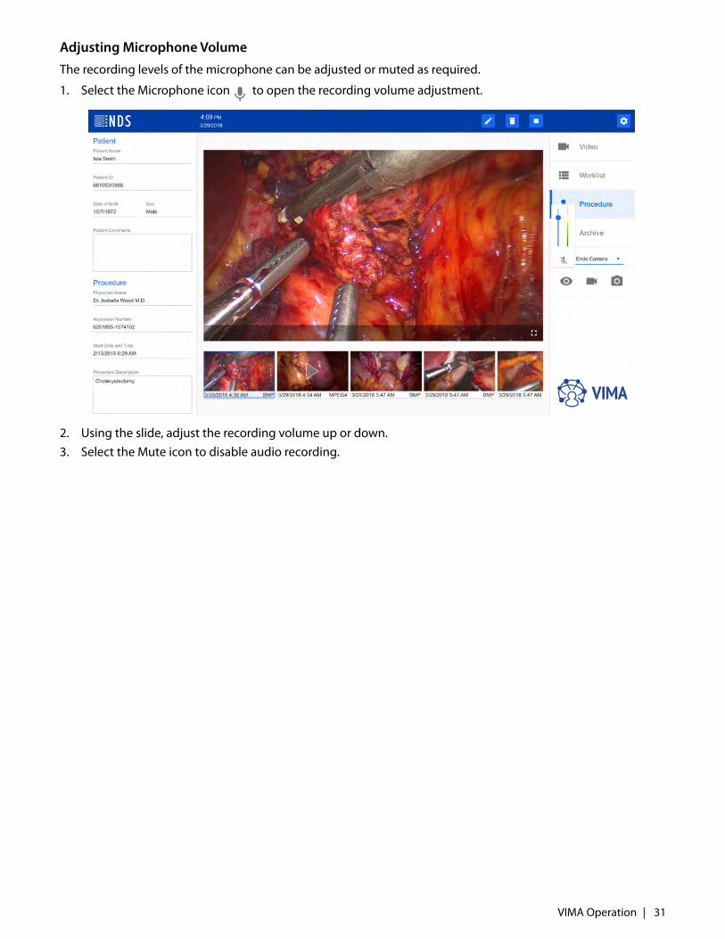
Adjusting Microphone Volume
The recording levels of the microphone can be adjusted or muted as required.
1. Select the Microphone icon to open the recording volume adjustment.
2. Using the slide, adjust the recording volume up or down. 3. Select the Mute icon to disable audio recording.
VIMA Operation | 31
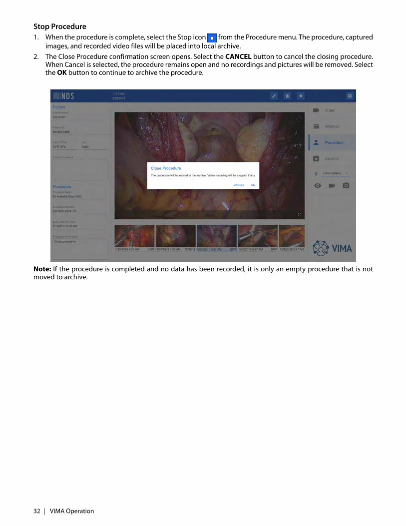
Stop Procedure1. When the procedure is complete, select the Stop icon from the Procedure menu. The procedure, captured
images, and recorded video files will be placed into local archive. 2. The Close Procedure confirmation screen opens. Select the CANCEL button to cancel the closing procedure.
When Cancel is selected, the procedure remains open and no recordings and pictures will be removed. Selectthe OK button to continue to archive the procedure.
Note: If the procedure is completed and no data has been recorded, it is only an empty procedure that is notmoved to archive.
32 | VIMA Operation
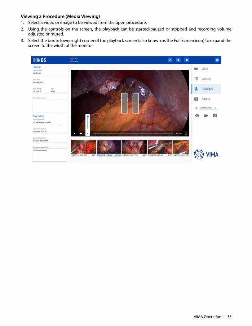
Viewing a Procedure (Media Viewing)1. Select a video or image to be viewed from the open procedure.2. Using the controls on the screen, the playback can be started/paused or stopped and recording volume
adjusted or muted.3. Select the box in lower-right corner of the playback screen (also known as the Full Screen icon) to expand the
screen to the width of the monitor.
VIMA Operation | 33
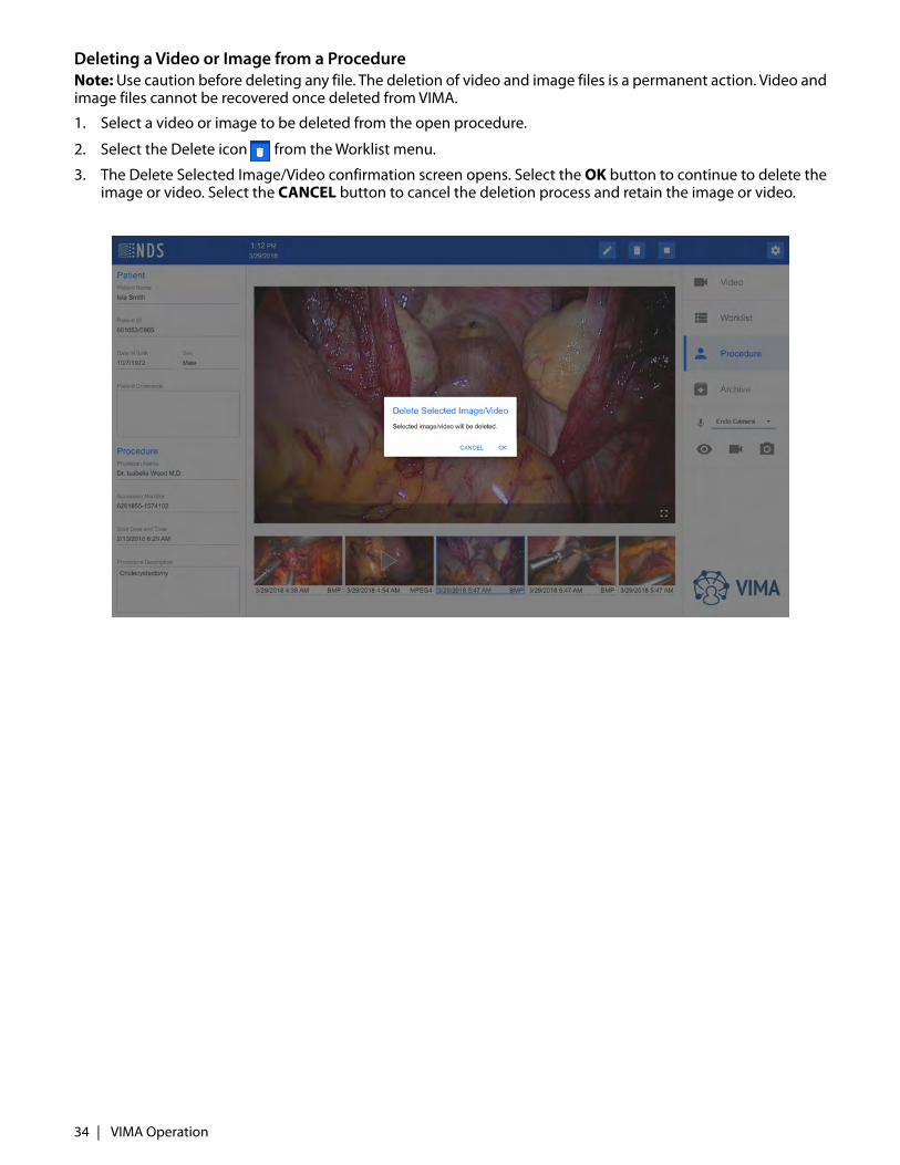
Deleting a Video or Image from a ProcedureNote: Use caution before deleting any file. The deletion of video and image files is a permanent action. Video andimage files cannot be recovered once deleted from VIMA.
1. Select a video or image to be deleted from the open procedure.
2. Select the Delete icon from the Worklist menu.
3. The Delete Selected Image/Video confirmation screen opens. Select the OK button to continue to delete theimage or video. Select the CANCEL button to cancel the deletion process and retain the image or video.
34 | VIMA Operation

Archive TabThe Archive screen contains all completed and saved procedures that have images or videos and were notdeleted. All recorded images and videos are saved with each procedure. The Archive is a local, temporary storagebefore exporting the data to PACS or other distribution. Data in the Archive is organized chronologically by dateof procedure completion, from the newest procedure to the oldest procedure. The Archive only containsarchived procedures that contain visual information (images or videos). If the record does not contain videoinformation, or is deleted during editing the record, then the whole record is deleted.
VIMA Operation | 35
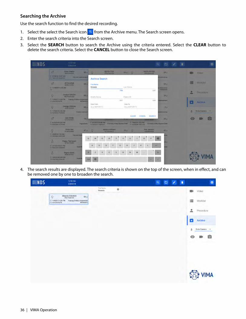
Searching the Archive
Use the search function to find the desired recording.
1. Select the select the Search icon from the Archive menu. The Search screen opens. 2. Enter the search criteria into the Search screen.3. Select the SEARCH button to search the Archive using the criteria entered. Select the CLEAR button to
delete the search criteria. Select the CANCEL button to close the Search screen.
4. The search results are displayed. The search criteria is shown on the top of the screen, when in effect, and canbe removed one by one to broaden the search.
36 | VIMA Operation
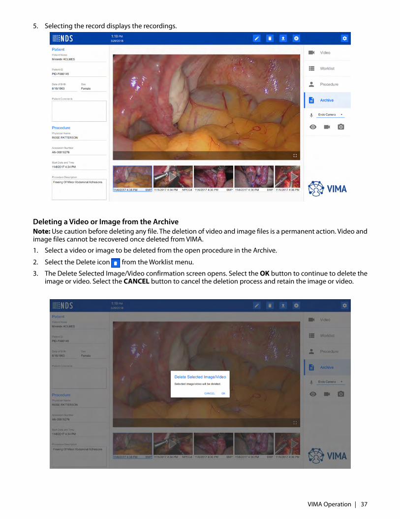
5. Selecting the record displays the recordings.
Deleting a Video or Image from the ArchiveNote: Use caution before deleting any file. The deletion of video and image files is a permanent action. Video andimage files cannot be recovered once deleted from VIMA.
1. Select a video or image to be deleted from the open procedure in the Archive.
2. Select the Delete icon from the Worklist menu.
3. The Delete Selected Image/Video confirmation screen opens. Select the OK button to continue to delete theimage or video. Select the CANCEL button to cancel the deletion process and retain the image or video.
VIMA Operation | 37
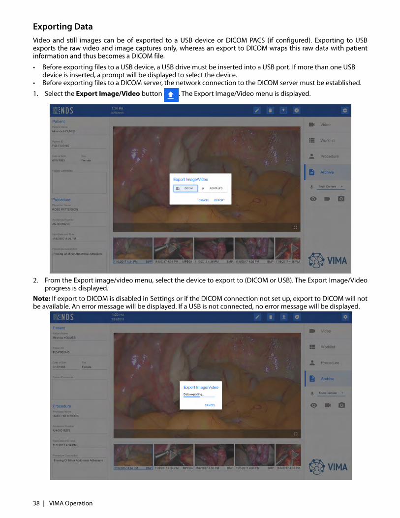
Exporting DataVideo and still images can be of exported to a USB device or DICOM PACS (if configured). Exporting to USBexports the raw video and image captures only, whereas an export to DICOM wraps this raw data with patientinformation and thus becomes a DICOM file.
• Before exporting files to a USB device, a USB drive must be inserted into a USB port. If more than one USB device is inserted, a prompt will be displayed to select the device.
• Before exporting files to a DICOM server, the network connection to the DICOM server must be established.
1. Select the Export Image/Video button . The Export Image/Video menu is displayed.
2. From the Export image/video menu, select the device to export to (DICOM or USB). The Export Image/Videoprogress is displayed.
Note: If export to DICOM is disabled in Settings or if the DICOM connection not set up, export to DICOM will notbe available. An error message will be displayed. If a USB is not connected, no error message will be displayed.
38 | VIMA Operation
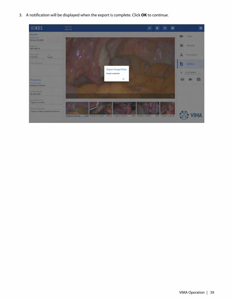
3. A notification will be displayed when the export is complete. Click OK to continue.
VIMA Operation | 39

VIMA Settings
General Settings
The General Settings includes two sections Language & Keyboard and Date & Time.
Configuring Language & Keyboard
Use the menu selections to select the language and keyboard layout. Select the SAVE button to save thechanges.
Note: Changing the Language requires an application restart to take effect. After you click Save, the confirmationdialog is shown. When the confirmation dialog is approved, the application is automatically restarted.
Configuring Date & Time
The configured date and time will be displayed in VIMA menu bar. Enter the current date, time, and time zone.Select the SAVE button to save the changes.
40 | VIMA Operation
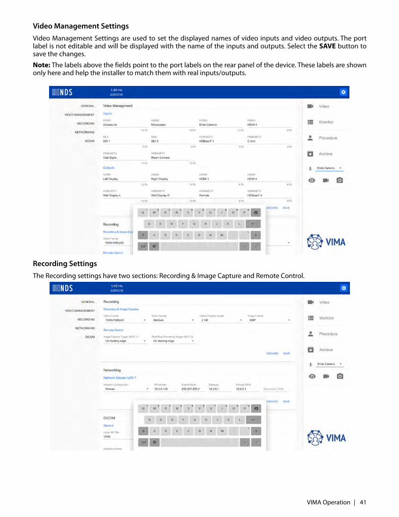
Video Management Settings
Video Management Settings are used to set the displayed names of video inputs and video outputs. The portlabel is not editable and will be displayed with the name of the inputs and outputs. Select the SAVE button tosave the changes.
Note: The labels above the fields point to the port labels on the rear panel of the device. These labels are shownonly here and help the installer to match them with real inputs/outputs.
Recording SettingsThe Recording settings have two sections: Recording & Image Capture and Remote Control.
VIMA Operation | 41
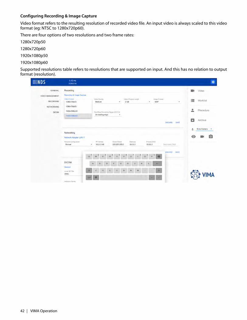
Configuring Recording & Image Capture
Video format refers to the resulting resolution of recorded video file. An input video is always scaled to this videoformat (eg: NTSC to 1280x720p60).
There are four options of two resolutions and two frame rates:
1280x720p50
1280x720p60
1920x1080p50
1920x1080p60
Supported resolutions table refers to resolutions that are supported on input. And this has no relation to outputformat (resolution).
42 | VIMA Operation
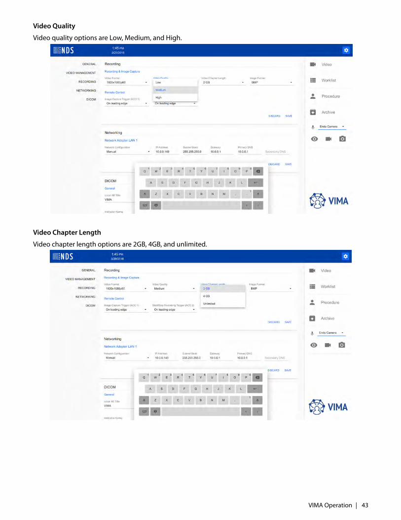
Video Quality
Video quality options are Low, Medium, and High.
Video Chapter Length
Video chapter length options are 2GB, 4GB, and unlimited.
VIMA Operation | 43
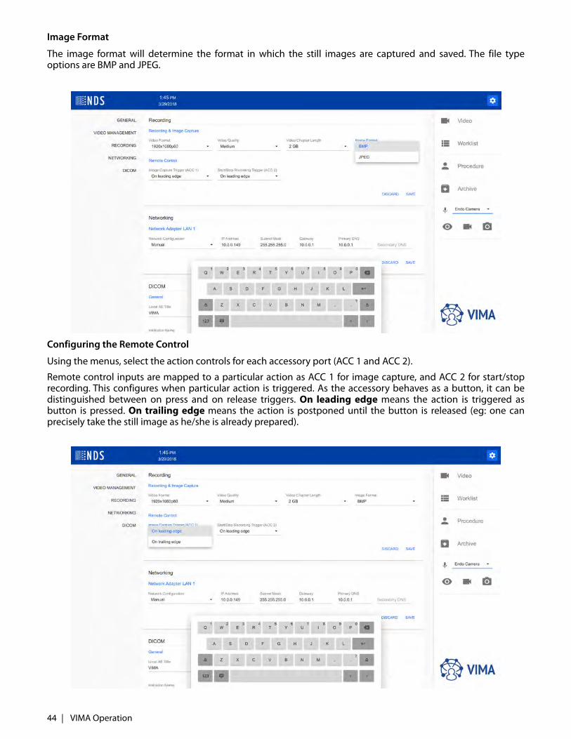
Image Format
The image format will determine the format in which the still images are captured and saved. The file typeoptions are BMP and JPEG.
Configuring the Remote Control
Using the menus, select the action controls for each accessory port (ACC 1 and ACC 2).
Remote control inputs are mapped to a particular action as ACC 1 for image capture, and ACC 2 for start/stoprecording. This configures when particular action is triggered. As the accessory behaves as a button, it can bedistinguished between on press and on release triggers. On leading edge means the action is triggered asbutton is pressed. On trailing edge means the action is postponed until the button is released (eg: one canprecisely take the still image as he/she is already prepared).
44 | VIMA Operation

Network Settings
Networking settings are used to configure the Network Adapter settings. The options include Manual and DHCP.
Note: This settings should be configured by an IT administrator.
VIMA Operation | 45

DICOM Settings
The DICOM settings include General, Worklist, Query, and Storage.
The General settings include the Local AE title, and character set selection. The name of the institution shouldalso be entered.
The Storage settings include Storage Commitment and Export Videos. Select to Enable or Disable thesefunctions as required.
46 | VIMA Operation

The Test buttons are used to test the connections after configuring the IP addresses, server ports, and server AEtitles for the worklist, query, storage. A message will indicate if the connection was successful or if it failed.
Note: The Administrator can enable use of storage commitment when needed.
Note: The Administrator can disable exporting videos to DICOM.
VIMA Operation | 47
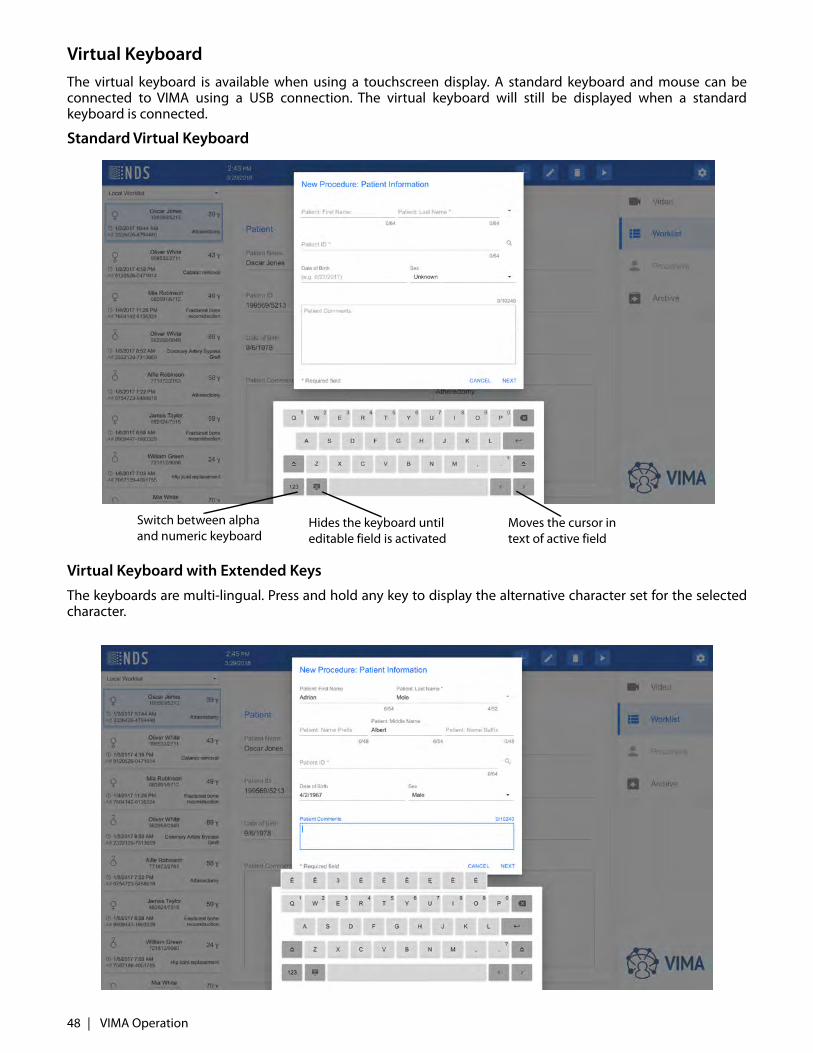
Virtual KeyboardThe virtual keyboard is available when using a touchscreen display. A standard keyboard and mouse can beconnected to VIMA using a USB connection. The virtual keyboard will still be displayed when a standardkeyboard is connected.
Standard Virtual Keyboard
Virtual Keyboard with Extended Keys
The keyboards are multi-lingual. Press and hold any key to display the alternative character set for the selectedcharacter.
Switch between alpha and numeric keyboard
Hides the keyboard until editable field is activated
Moves the cursor in text of active field
48 | VIMA Operation
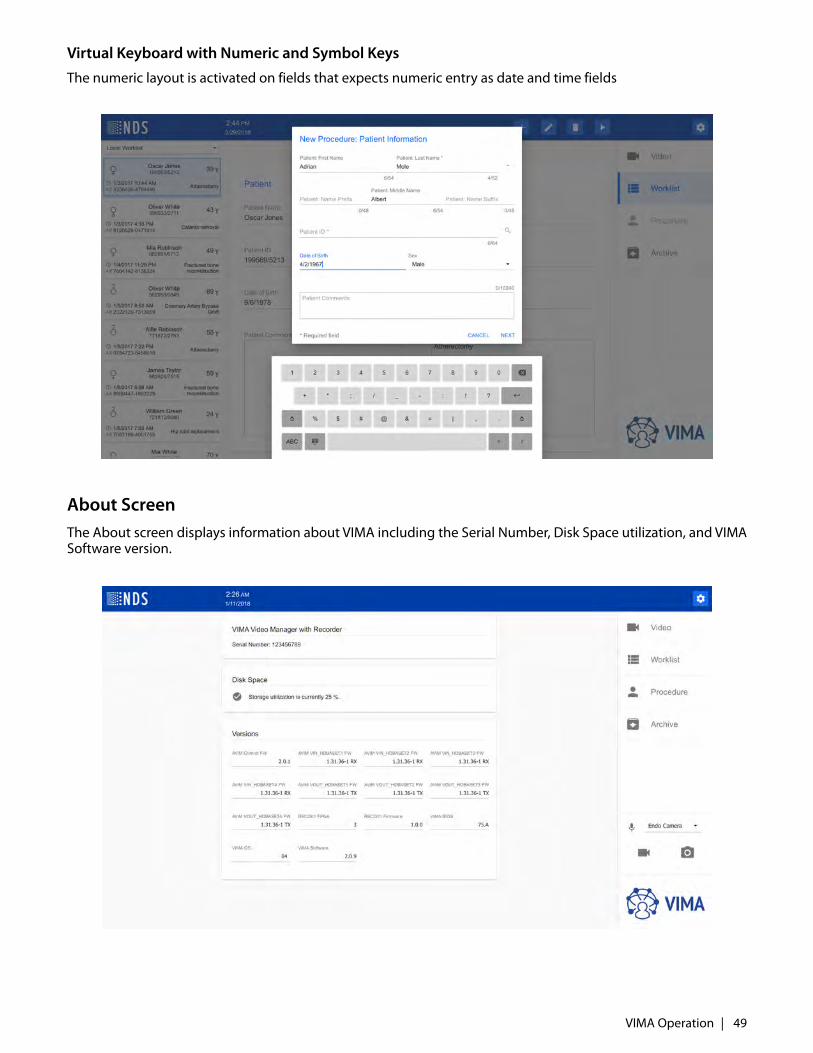
Virtual Keyboard with Numeric and Symbol Keys
The numeric layout is activated on fields that expects numeric entry as date and time fields
About Screen The About screen displays information about VIMA including the Serial Number, Disk Space utilization, and VIMASoftware version.
VIMA Operation | 49
Storage Space Utilization Warnings
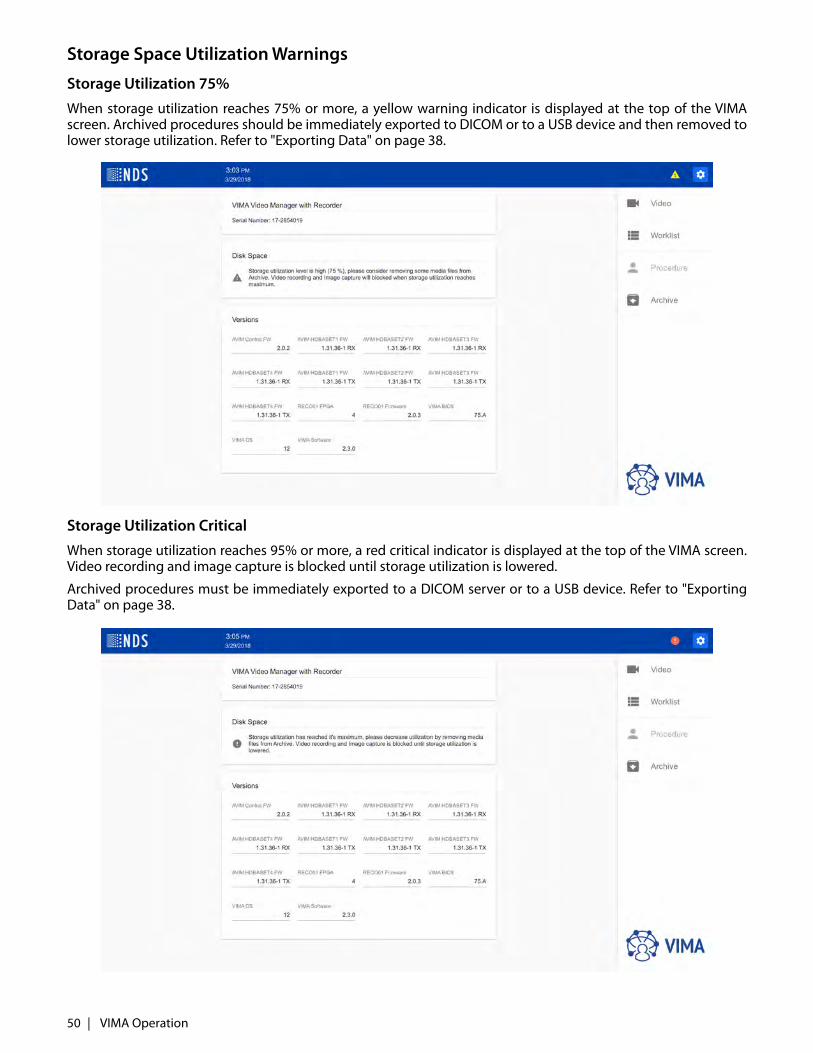
Storage Utilization 75%
When storage utilization reaches 75% or more, a yellow warning indicator is displayed at the top of the VIMAscreen. Archived procedures should be immediately exported to DICOM or to a USB device and then removed tolower storage utilization. Refer to "Exporting Data" on page 38.
Storage Utilization Critical
When storage utilization reaches 95% or more, a red critical indicator is displayed at the top of the VIMA screen.Video recording and image capture is blocked until storage utilization is lowered.
Archived procedures must be immediately exported to a DICOM server or to a USB device. Refer to "ExportingData" on page 38.
50 | VIMA Operation

Maintenance and Cleaning
Note: This product remains in the operating room and is not subject of normal maintenance cycle.
General InstructionsOnly use chemicals that are tested and approved. It is necessary to strictly follow the manufacturer instructionsfor use in matters of temperature, concentration and exposure time. Otherwise, you may encounter thefollowing problems:
• Damage like rust, cracks, breaks, premature aging or swelling.• Do not use any chemicals that elicit a plastic crevice corrosion or embrittlement.
Manual Cleaning and DisinfectionNote: Risk of electric shock and fire!
• Prior to cleaning and surface disinfection, the unit should be turned OFF and disconnected from its power source.
• Do not allow liquids to enter the interior of the unit.
Note: Risk of damage or destruction of the product during mechanical cleaning / disinfection!
• Clean / disinfect only by wiping the surface by hand.• Do not spray into open outlets (e. g. USB socket, input and output video signals, electrical outlet).• Never put into liquids nor rinse.• Never sterilize the product.
Note: Risk of damage to the product when inappropriate cleaning/disinfecting agents are used!
• For cleaning use only approved detergents and disinfectants, follow manufacturer's instructions.• Observe the information concerning concentration, temperature and exposure time.• Remove any visible remnants by disinfectant wipe.• Observe the contact time (1 min minimum).• Allow airing of the product after disinfection (at least 1 min).
Maintenance RequirementsThis unit does not require any maintenance other than periodic cleaning of the enclosure.
Cleaning InstructionsPrior to cleaning and surface disinfection, the unit should be turned OFF and disconnected from its powersource.
CleaningThoroughly wipe all exterior surfaces with a lint-free cloth that has been dampened with an acceptable cleaningagent. Acceptable cleaning materials are listed below. Remove residual detergent by wiping all exterior surfaceswith a lint-free cloth dampened with distilled water.
DisinfectingDisinfect the unit by wiping all exterior surfaces with a lint-free cloth dampened with 80% Ethyl Alcohol. Allowthe unit to air dry.
Warning: Do not allow liquids to enter the interior of the unit, as severe damage to the unit can result.Do not use solvents, abrasive detergents, or chemical cleaning cloths.
Acceptable Cleaning MaterialsVinegar (distilled white vinegar, 5% acidity)Ammonia-based glass cleaner
Acceptable Disinfecting MaterialEthanol 80% by volume
Maintenance and Cleaning | 51

Note: The acceptable cleaning and disinfecting materials listed above have been tested on NDS products and,when used as directed, do not harm the product’s finish and or its plastic components.
DisposalFollow local governing ordinances and recycling plans regarding the recycling or disposal of this equipment.
Recycling Passport is available at the supplier / manufacturer. (This passport contains recycling instructions fordisassembly the unit with information on proper disposal of harmful components for the environment).
52 | Maintenance and Cleaning
Specifications
Specifications are subject to change without notice. Contact your regional NDS headquarters for currentspecifications using contact information on the back cover.
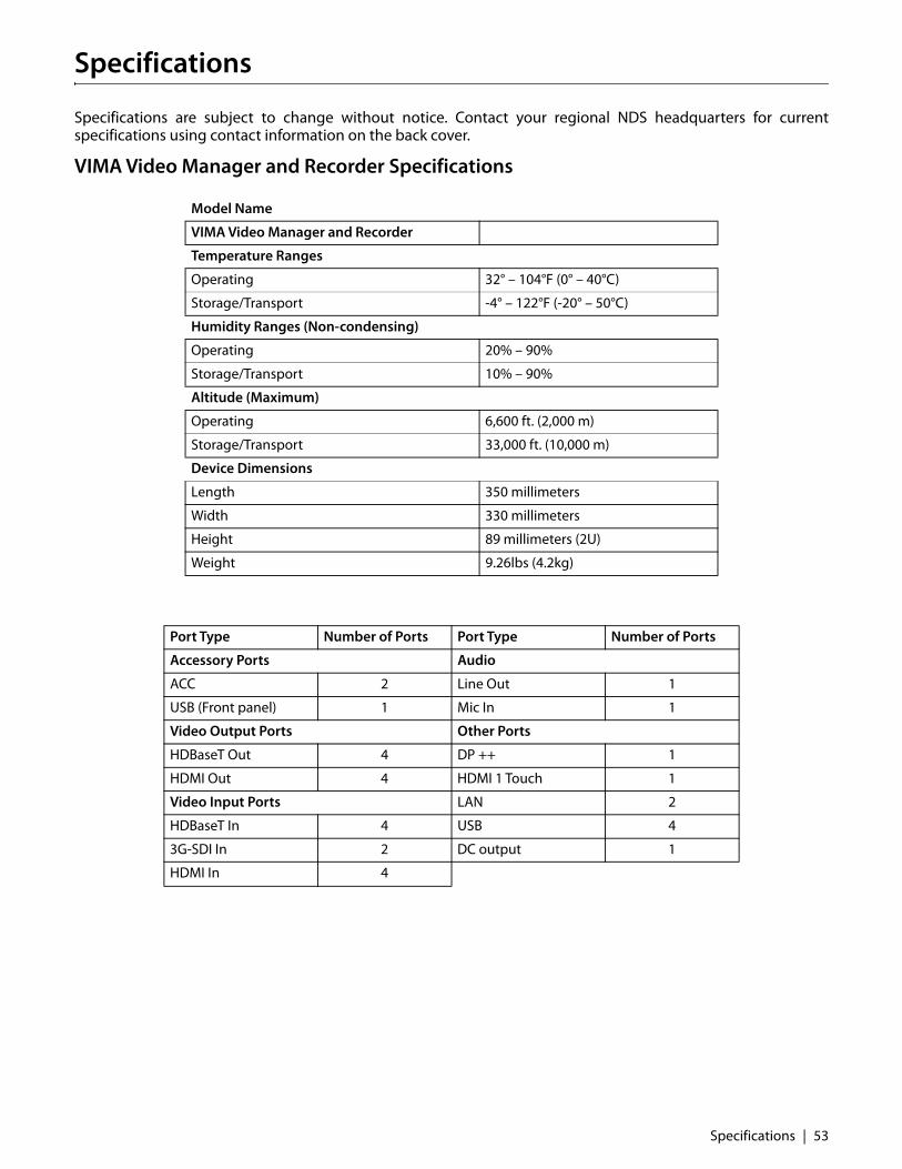
VIMA Video Manager and Recorder Specifications
Model Name
VIMA Video Manager and Recorder
Temperature Ranges
Operating 32° – 104°F (0° – 40°C)
Storage/Transport -4° – 122°F (-20° – 50°C)
Humidity Ranges (Non-condensing)
Operating 20% – 90%
Storage/Transport 10% – 90%
Altitude (Maximum)
Operating 6,600 ft. (2,000 m)
Storage/Transport 33,000 ft. (10,000 m)
Device Dimensions
Length 350 millimeters
Width 330 millimeters
Height 89 millimeters (2U)
Weight 9.26lbs (4.2kg)
Port Type Number of Ports Port Type Number of Ports
Accessory Ports Audio
ACC 2 Line Out 1
USB (Front panel) 1 Mic In 1
Video Output Ports Other Ports
HDBaseT Out 4 DP ++ 1
HDMI Out 4 HDMI 1 Touch 1
Video Input Ports LAN 2
HDBaseT In 4 USB 4
3G-SDI In 2 DC output 1
HDMI In 4
Specifications | 53
VIMA Video Recorder Specifications
Model Name
VIMA Video Recorder
Temperature Ranges
Operating 32° – 104°F (0° – 40°C)
Storage/Transport -4° – 122°F (-20° – 50°C)
Humidity Ranges (Non-condensing)
Operating 20% – 90%
Storage/Transport 10% – 90%
Altitude (Maximum)
Operating 6,600 ft. (2,000 m)
Storage/Transport 33,000 ft. (10,000 m)
Device Dimensions
Length 350 millimeters
Width 330 millimeters
Height 89 millimeters (2U)
Weight 7.5lbs (3.4kg)
Port Type Number of Ports
Accessory Ports
ACC 2
USB (Front panel) 1
Video Input Ports
HDBaseT In 1
3G-SDI In 1
DVI-D 1
Audio
Line Out 1
Mic In 1
Management and Control Ports
Display Port ++ 1
HDMI 1 Touch 1
LAN 2
USB 4
Other Ports
DC output 1
54 | Specifications
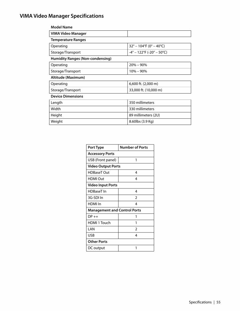
VIMA Video Manager Specifications
Model Name
VIMA Video Manager
Temperature Ranges
Operating 32° – 104°F (0° – 40°C)
Storage/Transport -4° – 122°F (-20° – 50°C)
Humidity Ranges (Non-condensing)
Operating 20% – 90%
Storage/Transport 10% – 90%
Altitude (Maximum)
Operating 6,600 ft. (2,000 m)
Storage/Transport 33,000 ft. (10,000 m)
Device Dimensions
Length 350 millimeters
Width 330 millimeters
Height 89 millimeters (2U)
Weight 8.60lbs (3.9 Kg)
Port Type Number of Ports
Accessory Ports
USB (Front panel) 1
Video Output Ports
HDBaseT Out 4
HDMI Out 4
Video Input Ports
HDBaseT In 4
3G-SDI In 2
HDMI In 4
Management and Control Ports
DP ++ 1
HDMI 1 Touch 1
LAN 2
USB 4
Other Ports
DC output 1
Specifications | 55

Power Consumption
Note: Interfaces ACC1 and ACC2 are not functional for the VIMA Video Manager only product variant.
Note: Specifications are subject to change without notice. Contact factory for recent specifications.
Data Storage CapacityThe following data storage is provided for the VIMA Video Manager and Recorder and the VIMA Video Recorder.
Note: The VIMA Video Manager does not provide data storage.
Maximal Power Consumption
VIMA Video Manager and Recorder 265W
VIMA Video Manager 260W
VIMA Video Recorder 90W
Power over Ethernet (PoE) Power Consumption VIMA Video Manager and Recorder
PoE Ports PoE Standard Max Power per Port
HDBaseT IN 1-4 802.3at Type 2 Class 4 30W
HDBaseT OUT 1-2 802.3at Type 2 Class 3 15W
Power over Ethernet (PoE) Power Consumption VIMA Video Recorder
PoE Ports PoE Standard Max Power per Port
HDBaseT IN 802.3at Type 2 Class 4 30W
Data Storage Capacity
VIMA Video Manager and Recorder Resolution 1920x1080 1280x720
Hours of low quality recording 160 230
Hours of medium quality recording 80 120
Hours of high quality recording 55 80
Number of JPEG images 500,000 900,000
Number of BMP images 75,000 170,000
VIMA Video Recorder Resolution 1920x1080 1280x720
Hours of low quality recording 160 230
Hours of medium quality recording 80 120
Hours of high quality recording 55 80
Number of JPEG images 500,000 900,000
Number of BMP images 75,000 170,000
VIMA Video Manager No data storage.
56 | Specifications
Supported Video Recording ResolutionsThe following list of supported resolutions apply to recorded video files. For more information about selecting avideo recording resolution, refer to “Configuring Recording & Image Capture” on page 42.There are four options of two resolutions and two frame rates:• 1280x720p50• 1280x720p60• 1920x1080p50• 1920x1080p60
Supported Video ResolutionsHDBaseT Product Variants: Video Manager; Video Manager with Recorder HDBaseT interfaces supports RGB in 8bit color depth.
Mode Name Mode Details Switching Recording/RecordingPreview
Input Preview
HD Video Modes
720p50 [email protected] Y Y Y
720p59 [email protected] Y Y Y
720p60 [email protected] Y Y Y
1080i25 [email protected] Y Y Y
1080i29 [email protected] Y Y Y
1080i30 [email protected] Y Y Y
1080p25 [email protected] Y Y Y
1080p29 [email protected] Y Y Y
1080p30 [email protected] Y Y Y
1080p50 [email protected] Y Y Y
1080p59 [email protected] Y Y Y
1080p60 [email protected] Y Y Y
Storz Image 1 50 Hz
[email protected] Y Y N
Storz Image 1 60 Hz
[email protected] Y Y N
SD Video Modes
480i29 [email protected] Y Y Y
480i30 [email protected] Y Y Y
480p59 [email protected] Y Y Y
480p60 [email protected] Y Y Y
576i25 [email protected] Y Y Y
576p50 [email protected] Y Y Y
Graphic Modes
DMT0660 [email protected] Y Y Y
DMT0672 [email protected] Y Y Y
DMT0675 [email protected] Y Y Y
DMT0685 [email protected] Y Y Y
DMT0785H [email protected] Y Y N
DMT0856 [email protected] Y Y Y
Specifications | 57

HDBaseT Product Variants: Video Recorder HDBaseT interface supports RGB in 8bit color depth.
DMT0860 [email protected] Y Y Y
DMT0872 [email protected] Y Y Y
DMT0875 [email protected] Y Y Y
DMT0885 [email protected] Y Y Y
DMT1060 [email protected] Y Y Y
DMT1070 [email protected] Y Y Y
DMT1075 [email protected] Y Y Y
DMT1260A [email protected] Y Y N
DMT1260G [email protected] Y Y Y
DMT1275G [email protected] Y Y Y
DMT1660 [email protected] Y Y N
CVR1960H [email protected] Y Y Y
CVR1960D [email protected] Y Y N
INT1440 [email protected] Y Y Y
1280x800 [email protected] Y Y Y
1360x768 [email protected] Y Y Y
1440X900 [email protected] Y Y Y
1680X1050 [email protected] Y Y Y
UHD Video Modes
2160p25 [email protected] Y N N
2160p29 [email protected] Y N N
2160p30 [email protected] Y N N
Mode Name Mode Details Recording/RecordingPreview
HD Video Modes
720p50 [email protected] Y
720p59 [email protected] Y
720p60 [email protected] Y
1080i25 [email protected] Y
1080i29 [email protected] Y
1080i30 [email protected] Y
1080p25 [email protected] Y
1080p29 [email protected] Y
1080p30 [email protected] Y
1080p50 [email protected] Y
1080p59 [email protected] Y
1080p60 [email protected] Y
Mode Name Mode Details Switching Recording/RecordingPreview
Input Preview
58 | Specifications

Storz Image 1 50 Hz
Storz Image 1 60 Hz
SD Video Modes
480i29 [email protected] Y
480i30 [email protected] Y
480p59 [email protected] Y
480p60 [email protected] Y
576i25 [email protected] Y
576p50 [email protected] Y
Graphic Modes
DMT0660 [email protected] Y
DMT0672 [email protected] Y
DMT0675 [email protected] Y
DMT0685 [email protected] Y
DMT0785H [email protected] Y
DMT0856 [email protected] Y
DMT0860 [email protected] Y
DMT0872 [email protected] Y
DMT0875 [email protected] Y
DMT0885 [email protected] Y
DMT1060 [email protected] Y
DMT1070 [email protected] Y
DMT1075 [email protected] Y
DMT1260A [email protected] Y
DMT1260G [email protected] Y
DMT1275G [email protected] Y
DMT1660 [email protected] Y
CVR1960H [email protected] Y
CVR1960D [email protected] Y
INT1440 [email protected] Y
1280x800 [email protected] Y
1360x768 [email protected] Y
1440X900 [email protected] Y
1680X1050 [email protected] Y
Mode Name Mode Details Recording/RecordingPreview
Specifications | 59
HDMI Product Variants: Video Manager; Video Manager with Recorder HDMI interfaces supports RGB in 8bit color depth.
Mode Name Mode Details Switching Recording/RecordingPreview
Input Preview
HD Video Modes
720p50 [email protected] Y Y Y
720p59 [email protected] Y Y Y
720p60 [email protected] Y Y Y
1080i25 [email protected] Y Y Y
1080i29 [email protected] Y Y Y
1080i30 [email protected] Y Y Y
1080p25 [email protected] Y Y Y
1080p29 [email protected] Y Y Y
1080p30 [email protected] Y Y Y
1080p50 [email protected] Y Y Y
1080p59 [email protected] Y Y Y
1080p60 [email protected] Y Y Y
Storz Image 1 50 Hz
[email protected] Y Y N
Storz Image 1 60 Hz
[email protected] Y Y N
SD Video Modes
480i29 [email protected] Y Y Y
480i30 [email protected] Y Y Y
480p59 [email protected] Y Y Y
480p60 [email protected] Y Y Y
576i25 [email protected] Y Y Y
576p50 [email protected] Y Y Y
Graphic Modes
DMT0660 [email protected] Y Y Y
DMT0672 [email protected] Y Y Y
DMT0675 [email protected] Y Y Y
DMT0685 [email protected] Y Y Y
DMT0785H [email protected] Y Y N
DMT0856 [email protected] Y Y Y
DMT0860 [email protected] Y Y Y
DMT0872 [email protected] Y Y Y
DMT0875 [email protected] Y Y Y
DMT0885 [email protected] Y Y Y
DMT1060 [email protected] Y Y Y
DMT1070 [email protected] Y Y Y
DMT1075 [email protected] Y Y Y
DMT1260A [email protected] Y Y N
DMT1260G [email protected] Y Y Y
60 | Specifications

DVI InterfaceProduct Variants: Video Recorder DVI interface supports RGB in 8bit color depth.
DMT1275G [email protected] Y Y Y
DMT1660 [email protected] Y Y N
CVR1960H [email protected] Y Y Y
CVR1960D [email protected] Y Y N
INT1440 [email protected] Y Y Y
1280x800 [email protected] Y Y Y
1360x768 [email protected] Y Y Y
1440X900 [email protected] Y Y Y
1680X1050 [email protected] Y Y Y
UHD Video Modes
2160p25 [email protected] Y N N
2160p29 [email protected] Y N N
2160p30 [email protected] Y N N
Mode Name Mode Details Recording/RecordingPreview
UHD Video Modes
720p50 [email protected] Y
720p59 [email protected] Y
720p60 [email protected] Y
1080i25 [email protected] Y
1080i29 [email protected] Y
1080i30 [email protected] Y
1080p25 [email protected] Y
1080p29 [email protected] Y
1080p30 [email protected] Y
1080p50 [email protected] Y
1080p59 [email protected] Y
1080p60 [email protected] Y
Storz Image 1 50 Hz
Storz Image 1 60 Hz
SD Video Modes
480i29 [email protected] Y
480i30 [email protected] Y
480p59 [email protected] Y
480p60 [email protected] Y
576i25 [email protected] Y
576p50 [email protected] Y
Mode Name Mode Details Switching Recording/RecordingPreview
Input Preview
Specifications | 61
Graphic Modes
DMT0660 [email protected] Y
DMT0672 [email protected] Y
DMT0675 [email protected] Y
DMT0685 [email protected] Y
DMT0785H [email protected] Y
DMT0856 [email protected] Y
DMT0860 [email protected] Y
DMT0872 [email protected] Y
DMT0875 [email protected] Y
DMT0885 [email protected] Y
DMT1060 [email protected] Y
DMT1070 [email protected] Y
DMT1075 [email protected] Y
DMT1260A [email protected] Y
DMT1260G [email protected] Y
DMT1275G [email protected] Y
DMT1660 [email protected] Y
CVR1960H [email protected] Y
CVR1960D [email protected] Y
INT1440 [email protected] Y
1280x800 [email protected] Y
1360x768 [email protected] Y
1440X900 [email protected] Y
1680X1050 [email protected] Y
Mode Name Mode Details Recording/RecordingPreview
62 | Specifications
3G-SDI InputProduct Variants: Video Manager; Video Manager with Recorder SDI interfaces supports YCbCr 4:2:2.
3G-SDI InputProduct Variants: Video Recorder SDI interfaces supports YCbCr 4:2:2.
Mode Name Mode Details Switching Recording/RecordingPreview
Input Preview
HD Video Modes
720p50 [email protected] Y Y Y
720p59 [email protected] Y Y Y
720p60 [email protected] Y Y Y
1080i25 [email protected] Y Y Y
1080i29 [email protected] Y Y Y
1080i30 [email protected] Y Y Y
1080p25 [email protected] Y Y Y
1080p29 [email protected] Y Y Y
1080p30 [email protected] Y Y Y
1080p50 [email protected] Y Y Y
1080p59 [email protected] Y Y Y
1080p60 [email protected] Y Y Y
SD Video Modes
480i29 [email protected] Y Y N
576i25 [email protected] Y Y N
Mode Name Mode Details Recording/RecordingPreview
HD Video Modes
720p50 [email protected] Y
720p59 [email protected] Y
720p60 [email protected] Y
1080i25 [email protected] Y
1080i29 [email protected] Y
1080i30 [email protected] Y
1080p25 [email protected] Y
1080p29 [email protected] Y
1080p30 [email protected] Y
1080p50 [email protected] Y
1080p59 [email protected] Y
1080p60 [email protected] Y
SD Video Modes
480i29 [email protected] Y
576i25 [email protected] Y
Specifications | 63
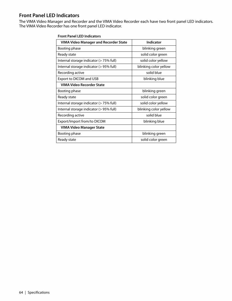
Front Panel LED IndicatorsThe VIMA Video Manager and Recorder and the VIMA Video Recorder each have two front panel LED indicators.The VIMA Video Recorder has one front panel LED indicator.
Front Panel LED Indicators
VIMA Video Manager and Recorder State Indicator
Booting phase blinking green
Ready state solid color green
Internal storage indicator (> 75% full) solid color yellow
Internal storage indicator (> 95% full) blinking color yellow
Recording active solid blue
Export to DICOM and USB blinking blue
VIMA Video Recorder State
Booting phase blinking green
Ready state solid color green
Internal storage indicator (> 75% full) solid color yellow
Internal storage indicator (> 95% full) blinking color yellow
Recording active solid blue
Export/Import from/to DICOM blinking blue
VIMA Video Manager State
Booting phase blinking green
Ready state solid color green
64 | Specifications
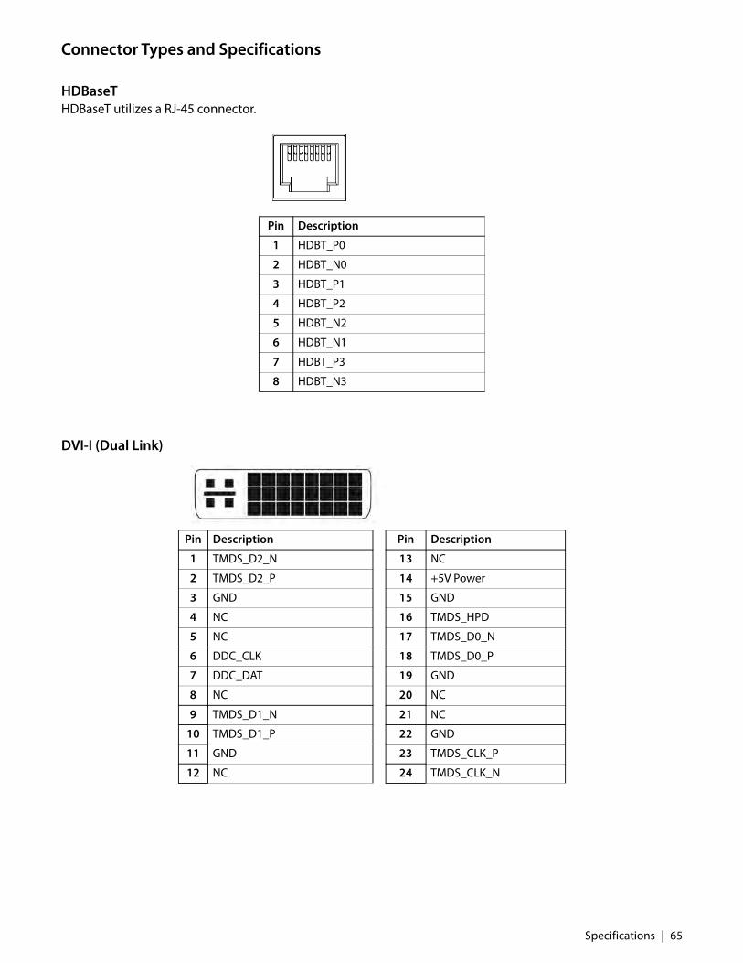
Connector Types and Specifications
HDBaseTHDBaseT utilizes a RJ-45 connector.
DVI-I (Dual Link)
Pin Description
1 HDBT_P0
2 HDBT_N0
3 HDBT_P1
4 HDBT_P2
5 HDBT_N2
6 HDBT_N1
7 HDBT_P3
8 HDBT_N3
Pin Description Pin Description
1 TMDS_D2_N 13 NC
2 TMDS_D2_P 14 +5V Power
3 GND 15 GND
4 NC 16 TMDS_HPD
5 NC 17 TMDS_D0_N
6 DDC_CLK 18 TMDS_D0_P
7 DDC_DAT 19 GND
8 NC 20 NC
9 TMDS_D1_N 21 NC
10 TMDS_D1_P 22 GND
11 GND 23 TMDS_CLK_P
12 NC 24 TMDS_CLK_N
Specifications | 65
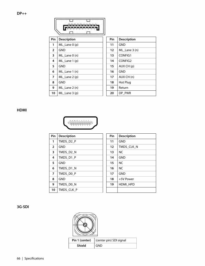
DP++
HDMI
3G-SDI
Pin Description Pin Description
1 ML_Lane 0 (p) 11 GND
2 GND 12 ML_Lane 3 (n)
3 ML_Lane 0 (n) 13 CONFIG1
4 ML_Lane 1 (p) 14 CONFIG2
5 GND 15 AUX CH (p)
6 ML_Lane 1 (n) 16 GND
7 ML_Lane 2 (p) 17 AUX CH (n)
8 GND 18 Hot Plug
9 ML_Lane 2 (n) 19 Return
10 ML_Lane 3 (p) 20 DP_PWR
Pin Description Pin Description
1 TMDS_D2_P 11 GND
2 GND 12 TMDS_CLK_N
3 TMDS_D2_N 13 NC
4 TMDS_D1_P 14 GND
5 GND 15 NC
6 TMDS_D1_N 16 NC
7 TMDS_D0_P 17 GND
8 GND 18 +5V Power
9 TMDS_D0_N 19 HDMI_HPD
10 TMDS_CLK_P
Pin 1 (center) (center pin) SDI signal
Shield GND
66 | Specifications

Line Out
Mic In
Control Connectors and Pinouts
RJ-45 Ethernet Connector
Pin Name
1 GND
2 LOUT-L
3 LOUT-R
Pin Name
1 GND
2 MIC-L
3 MIC-R
Pin Name Description
1 TX+ Transmit
2 TX- Transmit
3 RX+ Receive
4 No Connection
5 No Connection
6 RX- Receive
7 No Connection
8 No Connection
Specifications | 67

DC Connector
ACC1 and ACC2 Connectors
USB Connector
AC Power IN Connector
Pin Name
1 GND
2 12 V
3 GND
Pin Name
1 GND
2 Remote control contact
3 GND
Pin Name
1 +5 VDC
2 DATA -
3 DATA +
4 GND
Pin Name
1 Neutral
2 Ground/Earth
3 Live
1 4
68 | Specifications

Electromagnetic Compatibility Tables
WARNING: All medical electronic devices must conform to the requirements of IEC 60601-1-2. Precautions,adherences to the Electromagnetic Compatibility (EMC) guideline information provided in this manual andverification of all medical devices in simultaneous operation are required to ensure the electromagneticcompatibility and co-existence of all other medical devices prior to a surgical procedure.
The following EMC tables are provided for reference: Electromagnetic Emissions, Electromagnetic Immunity, andRecommended Separation Distances.Note: The emissions characteristics of this equipment make it suitable for use in industrial areas and hospitals (CISPR 11class A). If it is used in a residential environment (for which CISPR 11 class B is normally required) this equipment might notoffer adequate protection to radio-frequency communication services. The user might need to take mitigation measures,such as relocating or re-orienting the equipment.
Electromagnetic Emissions Immunity Test Test Level Professional Healthcare
Electrostatic discharge (ESD) IEC 61000-4-2 ±8 kV contact discharge±2, 4, 6, 8, 15 kV air discharge
Radiated RF field IEC 61000-4-3 3 V/m80 MHz - 2.7 GHz80% AM 1 kHz
Proximity fields from wireless transmitters IEC 61000-4-3
80MHz to 2700Hz. 3V/mSpot Tests: 385 MHz. at 27V/m;(710, 745, 780, 5240, 5500, 5785) MHz. at 9V/m;(450, 810, 870,930, 1720, 1845, 1970, 2450) MHz. at 28V/m
Electrical fast transient / burst IEC 61000-4-4 ±2 kV, AC mains±1 kV, I/O ports100 kHz PRR
Surge IEC 61000-4-5AC mains, Line to GroundAC mains, Line to Line
±0.5, 1, 2 kV±0.5, 1 kV
Conducted RF IEC 61000-4-6 3 V (0.15 - 80 MHz)6 V ISM Bands80% AM 1 kHz
Power frequency (50/60 Hz) magnetic field IEC 61000-4-8
30 A/m - 50 or 60 Hz
Voltage dips, short interruptions and voltage variations on power supply input lines IEC 61000-4-11
100% dip, 0.5 periods, 0°, 45°, 90°, 135°, 180°, 225°, 270°, 315° 100% dip, 1 period 30% dip, 25/30 periods (50/60 Hz) Interrupt 100% drop, 5 sec
Electromagnetic Compatibility Tables | 69

Recommended Separation Distances
Separation Distance NotesNote 1: At 80 MHz and 800 MHz, the separation distance for the higher frequency range applies.Note 2: These guidelines may not apply in all situations. Electromagnetic propagation is affected by absorption
and reflection from structures, objects and people.
Recommended Separation Distances Between Portable/Mobile RF Communications Equipment and the Product
This product is intended for use in an electromagnetic environment in which radiated RF disturbances are controlled.The customer or the user of this product can help prevent electromagnetic interference by maintaining a minimum distancebetween portable and mobile RF communications equipment (transmitters) and the product as recommended below,according to the maximum output power of the communications equipment.
Rated Maximum Output Power of Transmitter (W)
Separation Distance According to Frequency of Transmitter (m)
150 kHz to 80 MHz 80 MHz to 800 MHz 800 MHz to 2.5 GHz
0.01 0.12 0.12 0.23
0.10 0.38 0.38 0.73
1.00 1.20 1.20 2.30
10.00 3.80 3.80 7.30
100.00 12.00 12.00 23.00
For transmitters rated at a maximum output power not listed above, the recommended separation distance d in meters (m)can be estimated using the equation applicable to the frequency of the transmitter, where P is the maximum output powerrating of the transmitter in watts (W) according to the transmitter manufacturer.
70 | Electromagnetic Compatibility Tables

Symbol Glossary
Symbol alerts the user that important information regarding the installation and/or operation of this equipment follows. Information preceded by this symbol should be read carefully in order to avoid damage to the equipment.
Symbol for “Consult instructions for use” (User Manual), indicates the need for the user to consult the instructions for use.
Symbol cautions the user that important information regarding the operation and/or maintenance of this equipment has been included. Information preceded by this symbol should be read carefully to avoid damage to the equipment.
Symbol warns the user that non-insulated voltage within the unit may have sufficient magnitude to cause electrical shock, and signifies that it is dangerous to make contact with any part inside the unit. To reduce the risk of electric shock, DO NOT remove cover (or back).
Symbol for “Manufacturer”, indicates the medical device manufacturer.
Symbol for “Date of Manufacture”, indicates the date when the medical device was manufactured.
Symbol for “Authorized Representative in the European Community”, indicates the authorized representative in the European Community.
Symbol for “Catalogue Number”, indicates the manufacturer’s catalogue number so that the medical device can be identified.
Symbol for “Serial Number”, indicates the manufacturer’s serial number so that a specific medical device can be identified.
Symbol for “Batch Code”, indicates the manufacturer’s batch code so that the batch or lot can be identified.
Symbol for “Humidity Range”, indicates the range of humidity to which the medical device can be safely exposed.
Symbol for “Humidity Limitation”, indicates the acceptable upper and lower limits of relative humidity for transport and storage.
Symbol for “Atmospheric Pressure Limitation”, indicates the range of atmospheric pressure to which the medical device can be safely exposed.
Symbol for “Elevation Range”, indicates the need for the user to limit device usage within the elevation limits.
Symbol for “Temperature Limit”, indicates the temperature limits to which the medical device can be safely exposed.
Symbol for “This side up”, indicates products requiring an orientation on the packaging for handling and storage.
Symbol for “Keep dry”, indicates a medical device that needs to be protected from moisture.
Symbol for “Fragile, handle with care”, indicates a medical device that can be broken or damaged if not handled carefully.
REF
SN
LOT
<70%
Symbol Glossary | 71

United States Federal Communications Commission (FCC) symbol indicates EMC compliance per FCC standards.
The UL recognized component mark represents safety approval by Underwriter’s Laboratories for Canada and the United States.
The Canadian Standards Association (CSA) certification mark represents safety approval by Canadian Standards Association for Canada and the United States.
Technischer Überwachungsverein (TUV) symbol represents safety approval by TÜV Rheinland AG for Canada and the United States.
Conformité Européene (CE) mark of conformity certifies that the product is in compliance with EU health, safety, and environmental requirements.
EurAsian Conformity (EAC) mark represents safety approval by Custom Union countries: Belarus, Russia, Kazakhstan, Armenia, Kyrgyzstan.
China Compulsory Certificate (CCC) mark for Information Technology Equipment (ITE) products.
China Quality Certification (CQC) mark for uncategorized products.
China Restriction of Hazardous Substances (RoHS) green ”e” symbol indicates that the electrical and electronic product (EEP) does not contain restricted substances in amounts over maximum concentration values (MCV), and is an environmentally safe product that can be recycled.
China RoHS orange “number” symbol indicates that the EEP contains restricted substances. The symbol number refers in years to the Environmental Protection Use Period (EPUP), during which the product can be safely used, and following which should be immediately recycled.
Japan Telecom Engineering Center (TELEC) mark for wireless conformity certification.
The product packaging has been tested to be in compliance with International Safe Transit Association (ISTA) standards.
The Waste Electrical and Electronic Equipment (WEEE) symbol indicates a product that should be recycled or disposed of in compliance with local governing ordinances and recycling plans.
Electrical symbol for “Closed (On) Switch”, is located on the closed side of the device rocker switch.
Electrical symbol for “Open (Off ) Switch”, it appears on the open side of the device rocker switch.
Electrical symbol for “Equipotentiality” (Potential Equalization Terminal) identifies the Potential Equalization Conductor (ground post) of an electronic device.
Electrical symbol for “Protective Earth” (ground).
Electrical symbol for “Alternating Current” (AC).
Electrical symbol for “Direct Current” (DC).
72 | Symbol Glossary
This symbol indicates “Tipping Hazard.” To avoid potential injury, do not lean against the mobile device or attempt to move it before confirming that all casters are unlocked. Reference the user manual for more information.
Do not use equipment in magnetic resonance (MR) environments.
This symbol indicates electromagnetic interference may occur in the vicinity of equipment.
Symbol Glossary | 73

74 | Symbol Glossary

Terms and Conditions
This device is only to be operated within secured and cybersecurity compliant environments. It is theresponsibility of the product integration entity/user to ensure local governing laws and regulations are followedwithout limitations, such as HIPAA, GDPR, or other applicable cybersecurity rules, regulations, or laws.
Declarations of ConformityFCC and Council Directives of European StandardsThis device complies with Part 15 of FCC rules and 93/42/EEC and 2007/47/EC of the Council Directives ofEuropean Standards. Operation is subject to the following two conditions: (1) This device may not cause harmfulinterference, and (2) this device must accept any interference received, including interference that may causeundesirable results.
1. Use the attached specified cables with the color monitor so as not to interfere with radio and televisionreception. Use of other cable and adapters may cause interference with other electronic equipment.
2. This equipment has been tested and found to comply with the limits pursuant to FCC part 15 and CISPR 11.This equipment generates, uses and can radiate radio frequency energy and, if not installed and used inaccordance with the instructions, may cause harmful interference to radio communications.
IECThis equipment has been tested and found to comply with the limits for medical devices to the IEC 60601-1-2.These limits are designed to provide reasonable protection against harmful interference in a typical medicalinstallation. This equipment generates, uses and can radiate radio frequency energy and, if not installed andused in accordance with the instructions, may cause harmful interference to other devices in the vicinity.
FCC, Council Directives of European Standards, and IEC:There is no guarantee that interference will not occur in a particular installation. If this equipment does causeharmful interference to radio or television reception, which can be determined by turning the equipment off andon, the user is encouraged to try to correct the interference by one or more of the following measures:
• Reorient or relocate the receiving antenna.
• Increase the separation between the equipment and receiver.
• Connect the equipment into an outlet on a circuit different from that to which the receiver is connected.
• Consult your dealer or an experienced radio/TV technician for help.
Accessory equipment connected to this product must be certified according to the respective IEC Standards (i.e.,IEC 60950-1) for data processing equipment and IEC 60601-1 for medical equipment. Furthermore, allconfigurations shall comply with the system standard, IEC 60601-1-1. Anyone who connects additionalequipment to the signal input part or signal output part configures a medical system, and is thereforeresponsible that the system complies with the requirements of system standard IEC 60601-1-1. Whoever isresponsible for securing the unit to a system needs to insure that the mounting equipment used with thisproduct complies to IEC standard 60601-1. If in doubt, consult the technical services department or your localrepresentative.
Legal StatementNDS may sell its products through other medical device manufacturers, distributors and resellers and therefore,purchasers of this NDS product should consult with the entity through which this product was originallypurchased regarding the terms of any applicable product warranties provided by such entity, if any.
NDS neither assumes nor authorizes any person to assume for it any other liabilities in conjunction with and/orrelated to the sale and/or use of its products. To ensure proper use, handling and care of NDS products,customers should consult the product specific literature, instruction manual, and/or labeling included with theproduct or otherwise available.
Customers are cautioned that system configuration, software, the application, customer data and operatorcontrol of the system, among other factors, affect the product’s performance. While NDS products areconsidered to be compatible with many systems, specific functional implementation by customers may vary.Therefore, suitability of a product for a specific purpose or application must be determined by the consumer and
Terms and Conditions | 75
is not warranted by NDS.
NDS SPECIFICALLY DISCLAIMS ALL WARRANTIES OF ANY KIND, WHETHER EXPRESS, IMPLIED AND/ORSTATUTORY, INCLUDING, BUT NOT LIMITED TO WARRANTIES OF MERCHANTABILITY, FITNESS AND/OR OFSUITABILITY FOR A PARTICULAR PURPOSE, AND NON-INFRINGEMENT WITH RESPECT TO ALL NDS PRODUCTS ORSERVICES. ANY AND ALL OTHER WARRANTIES, REPRESENTATIONS AND/OR GUARANTEES, OF ANY TYPE, NATUREOR EXTENT, BE IT IMPLIED, EXPRESS AND/OR WHETHER ARISING UNDER OR AS A RESULT OF ANY STATUTE, LAW,COMMERCIAL USAGE, CUSTOM, TRADE OR OTHERWISE, ARE HEREBY EXPRESSLY EXCLUDED AND DISCLAIMED.
NDS, its suppliers and/or distributors are not liable, directly or by way of indemnity for any special, incidental,consequential, punitive, exemplary or indirect damages, including but not limited to alleged damages fordelayed shipment, non-delivery, product failure, product design or production, inability to use such products orservices, loss of future business (lost profits), or from any other cause, whatsoever, in connection with or arisingfrom the purchase, sale, lease, rental, installation or use of such NDS products, these terms and conditions, orwith respect to any the terms of any agreement which incorporates these terms and conditions.
SOME JURISDICTIONS DO NOT ALLOW EXCLUSIONS AND DISCLAIMERS OF CERTAIN WARRANTIES ORLIMITATIONS OF LIABILITY, SO THE LIMITATIONS AND/OR EXCLUSIONS, SET FORTH HEREIN, MAY NOT APPLY. INTHAT EVENT LIABILITY WILL BE LIMITED TO THE GREATEST EXTENT PERMITTED BY LAW IN THE SUBJECTJURISDICTION.
The information provided in this document, including all designs and related materials, is the valuable propertyof NDS and/or its licensors and, as appropriate, they reserve all patent, copyright, and other proprietary rights tothis document, including all design, manufacturing reproduction, use, and sales rights thereto, except to theextent said rights are expressly granted to others.
This user manual is subject to change without notice. If there is any concern about the latest instructions for use,please consult with NDS.
76 | Terms and Conditions

m
60A0773 Rev A
Global Headquarters
www.ndssi.com
5750 Hellyer Ave
San Jose, CA 95138
USA
+1 408 776 0085
Europe
Novanta Europe GmbH
Parkring 57-59
85748 Garching
Germany
+49 89 31 707 100
Asia Pacific
Novanta Japan
East Square Omori
6-20-14 Minamioi, Shinagawa-ku
Tokyo 140-0013
Japan
+81 3 5753 2466
Oriental Media Center
Suite 2302, Tower C
No.4, Guang Hua Road
Chao Yang District
Beijing, 100026
China
+86 10 8559 7859
NDS Quality System
ISO 9001 and ISO 13485
FDA Registration #2954921