6010-4 4 channel charger / adapter / led driver test
TRANSCRIPT

Basic version Standard version Value version Complete version
8F., No.88, Baojhong Rd., Sindian District 23144, New Taipei City, Taiwan (R.O.C.)TEL:886-2-2918-2620 FAX :886-2-2912-9870http://www.prodigi t .com.tw E-mail:sales@prodigi t .com.tw Prodigit Electronics Co., Ltd.
Feature
● 4 sets of U.U.T can be tested at the same time to improve test efficiency and save test time and cost● Select the required device configuration version ( Basic / Standard / Value / Complete version ) according to product testing requirements● Multi - function test capability for charger, adapter, LED driver power● Highly cost-effective, fully functional modular design test system● Operating environment of Windows 7 or higher (included)● Accept customized● Open architecture software platform
1. Support related hardware expansion
2. Edit test item function
3. Edit test program function
4. Edit statistical analysis report function
5. Online instrument control function
6. User authorization settings
7. Support Bar Code Reader
6010-4(33401G)
4 Channel Charger / Adapter / LED Driver Test System

AC Source
3340F / G Series
LED DC Load
4031 / 4032Timing &
Noise4013 (20A)
Power Meter4015APowerMeter
5061OVP
Source5303AVR
60104Mainframe
6010 Charger/Adapter/LED Driver Test i tem and equipment l ist
Test ItemEquipments
Brown-In Test
Brown-Out Test
Output adjust
Efficiency
Ripple Voltage
Output Voltage
Output Current
Output Performances
Input RMS Current
Input Frequency
Input Power
No Load Power Consumption
Input Power Factor
Input Inrush Current
Total Harmonic Distotion
IEC-61000-4-11 PQT Test
In p u t Ch arac te r is tics
Line Regulation
Load Regulation
Combine Regulation
Turn ON (Set-Up) Time
Turn OFF (Hold-Up) Time
Rise Time
Fall Time
Short Circuit
OV Protection
OC Protection
OP Protection
Timin g & Tran sien t
Pro tec tio n Tests
TTL Control
Relay Control
Others
Reg u la tio n Tests

6010-04 Charger/Adapter/LED Driver 4組 測試系統設備快選表
Test ItemEquipments
Brown-In Test
Brown-Out Test
Output adjust
Efficiency
Ripple Voltage
Output Voltage
Output Current
Output Performances
Input RMS Current
Input Frequency
Input Power
No Load Power Consumption
Input Power Factor
Input Inrush Current
Total Harmonic Distotion
IEC-61000-4-11 PQT Test
In p u t Ch arac te r is tics
Line Regulation
Load Regulation
Combine Regulation
Turn ON (Set-Up) Time
Turn OFF (Hold-Up) Time
Rise Time
Fall Time
Short Circuit
OV Protection
OC Protection
OP Protection
Timin g & Tran sien t
Pro tec tio n Tests
TTL Control
Relay Control
Others
Reg u la tio n Tests
6010-04-BStandard Version
6010-04-CValue Version
6010-04-DComplete Version
6010-04-ABasic Version

6010 4 Channel LED Driver test system Basic version configure need to 5302A/5310 or 2000VA AC Source) , 4 Channel Power Meter and Dual Channel DC Load (33401G Series), The Configure Diagram as below.
Input RMS Current
Input Frequency
Input Power
No Load Power Consumption
Input Power Factor
IEC-61000-4-11 PQT Test
Brown-In Test
Brown-In Test
Ou tp u t Perfo man ces
Short Circuit
OC Protection
OP Protection
Output Voltage
Output Current
Output adjust
Efficiency
Reg u la tio n TestsLine Regulation
Load Regulation
Combine Regulation
In p u t Ch arac te r is tics
Pro tec tio n Tests
6010-04-A 4 Channel Test System Basic Version System Diagram
6010-04-A 4 Channel Test System Basic Version test item list

1
2
1
1
1
1
O
CPU
SRAM
DRAM
Hard Driver
CD-ROM
Monitor
KeyBoard
I/O
System Interface
System I/O
○ Choose this interface When the System device use Note Book
500GB or higher
40X or faster
22"
101 Keys
Mouse/Print Port
i5-3470(3.2GHz) or faster
256KB
4GB or higher
Equipment Model N o.
5310 1KVAVA AC Power Source
33401G Series 150W x 2 LED DC Load Module
3305G 2 CH Mainframe
4013A 4 Chennel Power Meter
6010-04 System Software
1System Controller (PC)
Uport 1410 USB to RS-232 4 Port For Note Book
CP-104EL-A 1:4 High Speed RS-232 Interface Card
System Specifications ( PC or Note Book )
RS-232
1:4 or 1:8 High Speed RS-232 Card
OS : Windows 7.0 or later
Qt'y
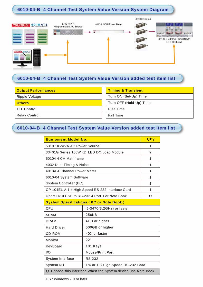
6010-04-B 4 Channel Standard Version (Basic Version + 4032 Noise & Timing
Analyzer) , The Conf igure Diagram as below
6010-04-A 4 Channel Test System Basic version equipment list
Turn ON (Set-Up) Time
Turn OFF (Hold-Up) Time
Rise Time
Fall Time
Output Performances
Ripple Voltage
OthersTTL Control
Relay Control
Timing & Transient
1
2
1
1
1
1
1
CPU
SRAM
DRAM
Hard Driver
CD-ROM
Monitor
KeyBoard
I/O
System Interface
System I/O
○ Choose this interface When the System device use Note Book
500GB or higher
40X or faster
22"
101 Keys
Mouse/Print Port
i5-3470(3.2GHz) or faster
256KB
4GB or higher
Equipment Model N o.
5310 1KVAVA AC Power Source
33401G Series 150W x2 LED DC Load Module
60104 4 CH Mainframe
4032 Dual Timing & Noise
14013A 4 Channel Power Meter
6010-04 System Software
CP-104EL-A 1:4 High Speed RS-232 Interface Card
OUport 1410 USB to RS-232 4 Port For Note Book
System Controller (PC)
System Specifications ( PC or Note Book )
RS-232
1:4 or 1:8 High Speed RS-232 Card
OS : Windows 7.0 or later
Qt'y
6010-04-B 4 Channel Test System Value Version added test item list
6010-04-B 4 Channel Test System Value Version added test item list
6010-04-B 4 Channel Test System Value Version System Diagram

6010-04-C 4 Channel Value Version (Standard Version + 4013A Change to 4015A
4CH Power Meter with Harmonic), The Configure Diagram as below
Input Characteristics
Total Harmonic Distotion
6010-04-C 4 Channel Test System Complete Version System Diagram
6010-04-C 4 Channel Test System Value Version added test item list

1
2
1
1
1
1
1
CPU
SRAM
DRAM
Hard Driver
CD-ROM
Monitor
KeyBoard
I/O
System Interface
System I/O
○ Choose this interface When the System device use Note Book
500GB or higher
40X or faster
22"
101 Keys
Mouse/Print Port
i5-3470(3.2GHz) or faster
256KB
4GB or higher
Equipment Model N o.
5310 1KVAVA AC Power Source
33401G Series 150W x2 LED DC Load Module
60104 4 CH Mainframe
4032 Dual Timing & Noise
14015A 4 CH Power Meter with Harmonic
6010-04 System Software
CP-104EL-A 1:4 High Speed RS-232 Interface Card
OUport 1410 USB to RS-232 4 Port For Note Book
System Controller (PC)
System Specifications ( PC or Note Book )
RS-232
1:4 or 1:8 High Speed RS-232 Card
OS : Windows 7.0 or later
Qt'y
6010-04-D 4 Channel Complete Version (Value Version + 5061 OVP Source & 5030 Inrush Source) The Configure Diagram as below
6010-04-C 4 Channel Test System Value version equipment list

OV Protection
Input Characteristics
Input Inrush Current
Pro tec tio n Tests
1
2
1
2
1
1
1
CPU
SRAM
DRAM
Hard Driver
CD-ROM
Monitor
KeyBoard
I/O
System Interface
System I/O
○ Choose this interface When the System device use Note Book
500GB or higher
40X or faster
22"
101 Keys
Mouse/Print Port
i5-3470(3.2GHz) or faster
256KB
4GB or higher
Equipment Model N o.
5310 1KVAVA AC Power Source
33401G Series 150W x2 LED DC Load Module
60104 4 CH Mainframe
4032 Dual Timing & Noise
14015A 4 CH Power Meter with Harmonic
1
1
6010-04 System Software
CP-104EL-A 1:4 High Speed RS-232 Interface Card
OUport 1410 USB to RS-232 4 Port For Note Book
System Controller (PC)
System Specifications ( PC or Note Book )
RS-232
1:4 or 1:8 High Speed RS-232 Card
OS : Windows 7.0 or later
Qt'y
5061 4 CH 120V OVP Source
5030 Inrush Sorce
6010-04-D 4 Channel Test System Complete Version System Diagram
6010-04-D 4 Channel Test System Complete Version added test item list
6010-04-D 4 Channel Test System Complete version equipment list
Power Rating
Voltage Rating
Frequency
Specifications
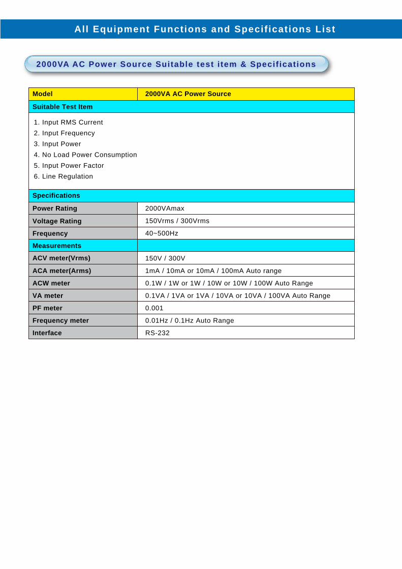
Model 2000VA AC Power Source
Suitable Test Item
1. Input RMS Current2. Input Frequency3. Input Power4. No Load Power Consumption5. Input Power Factor6. Line Regulation
2000VAmax
150Vrms / 300Vrms
40~500Hz
Measurements
ACV meter(Vrms)
ACA meter(Arms)
ACW meter
VA meter
PF meter
Frequency meter
Interface
150V / 300V
1mA / 10mA or 10mA / 100mA Auto range
0.1W / 1W or 1W / 10W or 10W / 100W Auto Range
0.1VA / 1VA or 1VA / 10VA or 10VA / 100VA Auto Range
0.001
0.01Hz / 0.1Hz Auto Range
RS-232
All Equipment Functions and Specif ications List
2000VA AC Power Source Suitable test i tem & Specif ications

For IEC-61000-4-11
Classaa Test level and durations for voltage dips(ts) (50 Hz/60 Hz)
Table 1 - Preferred test level and durations for voltage dips
Case-by-case according to the equipment requirementsClass 1
Class 2
Class 3
Class Xb
0 % during1/2 cycle
0 % during1/2 cycle
0 % during1 cycle
0 % during1 cycle
70 % during 25/30c cycles
40 % during10/12c cycles
70 % during25/30c cycles
80 % during250/300c cycles
X X X
X
X X
a Classes as per IEC 61000-2-4; see Annex B.
b To be defined by product committee. For equipment connected directly or indirectly to the public network, the levels must not be less severe than Class 2.
c “25/30 cycles” means “25 cycles for 50 Hz test” and “30 cycles for 60 Hz test”
Classaa Classa Test level and durations for short interruptions (ts) (50 Hz/60 Hz)
Table 2 - Preferred test level and durations for short interruptions
Case-by-case according to the equipment requirements
0 % dur ing 250/300c cycles
0 % dur ing 250/300c cycles
Class 1
Class 2
Class 3
Class Xb
a Classes as per IEC 61000-2-4 ; see Annex B.
b To be defined by product committee. For equipment connected directly or indirectly to the public network, the levels must not be less severe than Class 2.
c “250/300 cycles” means “250 cycles for 50 Hz test” and “300 cycles for 60 Hz test”
Voltage test level Time for decreasing voltage (td)
Time at reduced voltage (ts)
Time for increasing voltage (ti) (50 Hz/60 Hz)
Table 3 - Timing of short-term supply voltage variations
a To be defined by product committee.
b “25/30 cycles” means “25 cycles for 50 Hz test” and “30 cycles for 60 Hz test”.
70% Abrupt 1 cycle 25/30b cycles
Xa Xa Xa Xa

Power Rating
Voltage Rating
Current Rating
Frequency
Angle(ON/OFF)
PQT <IEC 61000-4-11 >
Measurements
ACV meter(Vrms)
ACA meter(Arms)
Specifications
Model 5310 1KVA AC Power Source
Suitable Test Item
1. Input RMS Current2. Input Frequency3. Input Power4. No Load Power Consumption5. Input Power Factor6. Input Voltage Sag7. Line Regulation8. A voltage ON/OFF angle ( 0 ~ 360°) Can be programmed
40~70Hz
Triac Mode Leading / Trailing Edge
0~360°
DIP, Interrupt, Variation
1000 VAmax
150Vpeak/250Vpeak/300Vpeak/350Vpeak/450Vpeak/500Vpeak
7Apeak/5Apeak/3.5Apeak/3Apeak/2.3Apeak/2Apeak
500V / 0.1V resolution
7 A / 0.001A resolution
ACW meter 1000W / 0.001W resolution
For USB PD Sag
0.5 Cycle
Duration TimeDip Voltage (Vin=110Vac/60Hz) Dip Voltage (Vin=230Vac/50Hz)
PF meter
Frequency meter
Interface
±0.01~1.00
40~70 Hz / 0.1Hz resolution
RS-232
25% 50% 100% 25% 50% 100%
S S S S S S1 Cycle S S S S S S5 Cycle S R R S R R
10 Cycle S R R S R R
* S means that the output must meet specifications
* R means the output can be automatically restored to 5V output
5310 1KVA AC Power Source Suitable test i tem & Specif ications

Specifications
Model 4031 Noise & Timing Analyzer Module
Suitable Test Item
No. of input channel 1Timing Measurement
Voltage rangeMeasurement rangeResolut ionCurrent rangeMeasurement rangeResolut ionAccuracySampling RateUpdate RateResolut ion
0 ~ 100 KHz0 ~ 80 / 600 Vdc0 ~ 3.2 / 20 Vp-p
0.001/0.01V*(1/4F.S.) / (F.S.) Adc
*(1/8F.S.) / (1/2F.S.) Ap-p0.001 / 0.01A
±5% of (Reading + Range)100KHz
50~1000 mS1mS
Band WidthCurrent rangeResolut ionAccuracySampling RateUpdate RateResolut ionFrequency rangeResolut ionAccuracyDuty(Ton) RangeResolut ionAccuracy
100KHz*(1/8F.S.) / (1/2F.S.) Adc
0.001 / 0.01A±5% of (Reading + Range)
100KHz50~1000 mS
1mS10Hz~35KHz
1Hz±1% of (Reading + Range)
3uS~90mS1uS
±1% of (Reading + Range)
2. Turn ON(Set-Up) Time3. Turn OFF(Hold-Up) Time4. Rise Time5. Fall Time
Ripple MeasurementBand Width
1. Ripple Voltage
Set-up / Hold-up / Rise / Fall TimeVoltage rangeCurrent rangeTiming rangeResolut ionVth1 / Vth2Voltage rangeResolut ionAccuracy
Low Pass FilterVoltage rangeResolut ionAccuracy
Band WidthVoltage rangeMeasurement rangeResolut ionCurrent rangeMeasurement rangeResolut ionAccuracySampling RateUpdate RateResolut ion
Noise Measurement
Over Shoot Measurement
0 ~ 80 / 600 Vdc*(1/4F.S.) / (F.S.) Adc
1 Sec / 2 Sec / 4 Sec / 8 Sec / 16 Sec1 uS / 2uS / 4uS / 8uS / 16uS
5% ~ 95% of reading0.01 V / 0.01V, 0.001A / 0.01A
±2% of (Reading + Range)
up to 20 MHz0.6 / 3Vp-p
1mV±2% OF reading + 5mV
0 ~ 100 KHz0~80 / 600Vdc
0 ~ 80 / 600 Vdc0.01 / 0.1Vdc
*(1/4F.S.) / (F.S.) Adc*(1/4F.S.) / (F.S.) Adc
0.001 / 0.01A±5% of (Reading + Range)
100KHz50~1000 mS
1mS
Dimming Measurement
4031 Noise & Ripple Meter suitable test item & Specification

Specifications
Model 4032-PD Noise & Timing Analyzer Module
No. of input channel 2Timing Measurement
Voltage rangeMeasurement rangeResolut ionCurrent rangeMeasurement rangeResolut ionAccuracySampling RateUpdate RateResolut ion
0 ~ 100 KHz0 ~ 80 / 600 Vdc0 ~ 3.2 / 24 Vp-p
0.001 / 0.01V0 ~ 0.8 / 3.2 Adc0 ~ 0.4 / 1.6 Ap-p
0.001 / 0.01A±5% of (Reading + Range)
100KHz50~1000 mS
1mS
Band WidthCurrent rangeResolut ionAccuracySampling RateUpdate RateResolut ionFrequency rangeResolut ionAccuracyDuty(Ton) RangeResolut ionAccuracy
100KHz0 ~ 0.8 / 3.2 Adc
0.001 / 0.01A±5% of (Reading + Range)
100KHz50~1000 mS
1mS10Hz~35KHz
1Hz±1% of (Reading + Range)
3uS~90mS1uS
±1% of (Reading + Range)
Ripple MeasurementBand WidthSet-up / Hold-up / Rise / Fall Time
Voltage rangeCurrent rangeTiming rangeResolut ionVth1 / Vth2Voltage rangeResolut ionAccuracy
Low Pass FilterVoltage rangeResolut ionAccuracy
Band WidthVoltage rangeMeasurement rangeResolut ionCurrent rangeMeasurement rangeResolut ionAccuracySampling RateUpdate RateResolut ion
Noise Measurement
Over Shoot Measurement
Dimming Measurement
1. Ripple Voltage2. Turn ON(Set-Up) Time3. Turn OFF(Hold-Up) Time
0 ~ 80 / 600 Vdc0~0.8/3.2Adc
0~1 Sec10uS
5% ~ 95% of reading0.1 V/1V, 0.001A/0.01A
±2% of (Reading + Range)
up to 20 MHz0.6 / 3Vp-p
1mV±2% OF reading + 5mV
0 ~ 100 KHz0 ~ 80 / 600 Vdc0 ~ 80 / 600 Vdc
0.1 / 1Vdc0 ~ 0.8 / 3.2 Adc0 ~ 0.8 / 3.2 Adc
0.001 / 0.01A±5% OF (Reading + Range)
100KHz50~1000 mS(1/Fs * 20000)
1mS
4. Rise Time5. Fall Time
Note : F.S. Load Current range
4032 Noise & Ripple Meter suitable test item & Specification
Suitable Test Item
Specifications
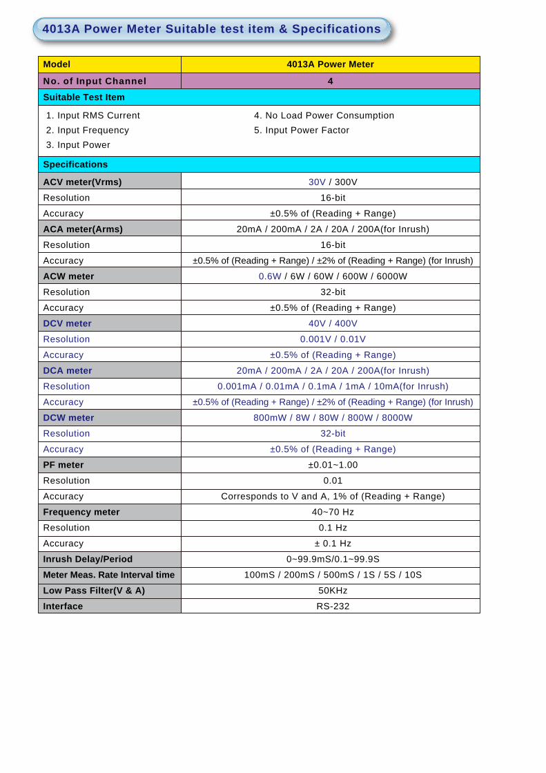
No. of Input Channel
Model 4013A Power Meter
Suitable Test Item
1. Input RMS Current2. Input Frequency3. Input Power
4. No Load Power Consumption5. Input Power Factor
4
ACV meter(Vrms)Resolution
Accuracy
ACA meter(Arms)Resolution
Accuracy
ACW meterResolution
Accuracy
DCV meterResolution
Accuracy
DCA meterResolution
Accuracy
DCW meterResolution
Accuracy
PF meterResolution
Accuracy
Frequency meterResolution
Accuracy
Inrush Delay/PeriodMeter Meas. Rate Interval timeLow Pass Filter(V & A)Interface
30V / 300V
16-bit
±0.5% of (Reading + Range)
20mA / 200mA / 2A / 20A / 200A(for Inrush)
16-bit
±0.5% of (Reading + Range) / ±2% of (Reading + Range) (for Inrush)
0.6W / 6W / 60W / 600W / 6000W
32-bit
±0.5% of (Reading + Range)
40V / 400V
0.001V / 0.01V
±0.5% of (Reading + Range)
20mA / 200mA / 2A / 20A / 200A(for Inrush)
0.001mA / 0.01mA / 0.1mA / 1mA / 10mA(for Inrush)
±0.5% of (Reading + Range) / ±2% of (Reading + Range) (for Inrush)
800mW / 8W / 80W / 800W / 8000W
32-bit
±0.5% of (Reading + Range)
±0.01~1.00
0.01
Corresponds to V and A, 1% of (Reading + Range)
40~70 Hz
0.1 Hz
± 0.1 Hz
0~99.9mS/0.1~99.9S
100mS / 200mS / 500mS / 1S / 5S / 10S
50KHz
RS-232
4013A Power Meter Suitable test item & Specifications
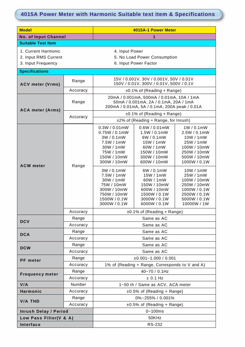
No. of Input Channel4015A-1 Power Meter
Suitable Test Item1
Model
ACV meter (Vrms)
ACA meter (Arms)
ACW meter
Specifications
0.3W / 0.01mW0.75W / 0.1mW
3W / 0.1mW7.5W / 1mW30W / 1mW75W / 1mW
150W / 10mW300W / 10mW
0.6W / 0.01mW1.5W / 0.1mW6W / 0.1mW15W / 1mW60W / 1mW
150W / 10mW300W / 10mW600W / 10mW
1W / 0.1mW2.5W / 0.1mW
10W / 1mW25W / 1mW
100W / 10mW250W / 10mW500W / 10mW1000W / 0.1W
15V / 0.001V, 30V / 0.001V, 50V / 0.01V150V / 0.01V, 300V / 0.01V, 500V / 0.1V
Accuracy ±0.1% of (Reading + Range)
3W / 0.1mW7.5W / 1mW30W / 1mW
75W / 10mW300W / 10mW750W / 10mW1500W / 0.1W3000W / 0.1W
6W / 0.1mW15W / 1mW60W / 1mW
150W / 10mW600W / 10mW1500W / 0.1W3000W / 0.1W6000W / 0.1W
10W / 1mW25W / 1mW
100W / 10mW250W / 10mW1000W / 0.1W2500W / 0.1W5000W / 0.1W10000W / 1W
Range
±0.1% of (Reading + Range)20mA / 0.001mA, 500mA / 0.01mA, 10A / 1mA
50mA / 0.001mA, 2A / 0.1mA, 20A / 1mA200mA / 0.01mA, 5A / 0.1mA, 200A peak / 0.01A
±0.1% of (Reading + Range)±2% of (Reading + Range, for Inrush)
0~100ms
1% of (Reading + Range, Corresponds to V and A)40~70 / 0.1Hz
± 0.1 Hz1~50 th / Same as ACV, ACA meter
±0.5% of (Reading + Range)0%~255% / 0.001%
±0.5% of (Reading + Range)
Same as ACSame as ACSame as AC
±0.001~1.000 / 0.001
50KHzRS-232
Same as ACSame as ACSame as AC
Range
Accuracy
Range
Accuracy
V/AHarmonic
Inrush Delay / Period
Frequency meter
V/A THD
DCW
PF meter
Low Pass Fi l ter(V & A)Interface
DCV
DCA
RangeAccuracy
Range
RangeAccuracy
Range
RangeAccuracyNumber
AccuracyRange
Accuracy
Accuracy
Accuracy
1. Current Harmonic2. Input RMS Current3. Input Frequency
4. Input Power5. No Load Power Consumption6. Input Power Factor
4015A Power Meter with Harmonic Suitable test item & Specifications

Model 5303 AVR
Suitable Test Item
Specifications1. Input Inrush Current
3KVA
CF > 7
230Vrms +/- 10%
230,264,277Vrms Selectable
±2.5Vrms
Power Rating
Maximum Capacity
Input Voltage Rating
Output Voltage Rating
Accuracy
Interface RS-232 remote control only
Model 5060-1 OVP Source
1. Over Voltage Protection
Power RatingVoltage rangeResolution
Current rangeResolution
Ton Step timeResolution
Slew rateProtection
*1 The maximum power apply for 1 Sec. at 50% duty cycle.
80W *1
0.1 mSec.
0.02V / uS
OCP, OTP
0.001V
0~4A / 2A
0.1mA
0~6.5 Sec.
0~20V / 40V
Model 5060-1 OVP Source
1. Over Voltage Protection
Power RatingVoltage rangeResolution
Current rangeResolution
Ton Step timeResolution
Slew rateProtection
*1 The maximum power apply for 1 Sec. at 50% duty cycle.
80W *1
0.1 mSec.
0.02V / uS
OCP, OTP
0.01VAccuracy ±0.5% of (Setting + Range)
0~1.4A / 0.7A
0.1mA
Accuracy ±0.5% of (Setting + Range)
0~6.5 Sec.
0~60V / 120V
5303 AVR Suitable test i tem & Specif ications
5060/5061 OVP Source Suitable test item & Specifications
Suitable Test Item
Specifications
Suitable Test Item
Specifications
6010-04-A(33401G)4 channel Charger / Adapter /
LED Driver Test System
6010-04-B(33401G)4 channel Charger / Adapter /
LED Driver Test System
6010-04-C(33401G)4 channel Charger / Adapter /
LED Driver Test System
6010-04-D(33401G)4 channel Charger / Adapter /
LED Driver Test System
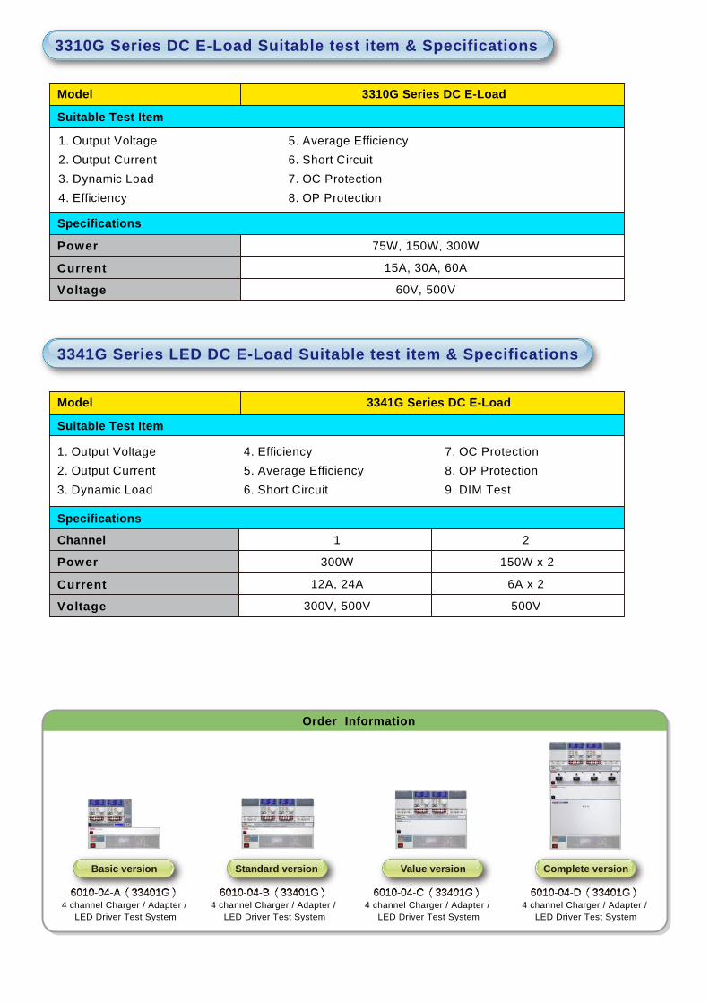
Order Information
6010-04-A(33401G) 6010-04-B(33401G) 6010-04-C(33401G) 6010-04-D(33401G)
Basic version Standard version Value version Complete version
Power
Current
Voltage
Model 3310G Series DC E-Load
1. Output Voltage2. Output Current3. Dynamic Load4. Efficiency
5. Average Efficiency6. Short Circuit7. OC Protection8. OP Protection
15A, 30A, 60A
60V, 500V
75W, 150W, 300W
Power
Current
Voltage
Model 3341G Series DC E-Load
1. Output Voltage2. Output Current3. Dynamic Load
4. Efficiency5. Average Efficiency6. Short Circuit
7. OC Protection8. OP Protection9. DIM Test
12A, 24A
300V, 500V
300W
Channel 1
6A x 2
500V
150W x 2
2
3341G Series LED DC E-Load Suitable test item & Specifications
3310G Series DC E-Load Suitable test item & Specifications
Suitable Test Item
Specifications
Suitable Test Item
Specifications