60-ghz cmos transceivers: why and how? - ieee · 60-ghz cmos transceivers: why and how? behzad...
TRANSCRIPT

60-GHz CMOS Transceivers: Why and How?
Behzad Razavi
Electrical Engineering Department
University of California, Los Angeles

2
Outline
IntroductionReceiver Front EndTransmitter Front EndFrequency DividerReflectionsConclusion

3
Why 60 GHz?
7 GHz of Unlicensed BandPossibility of Realizing (Multiple) On-Chip Antennas:- Low-Cost Packaging- Differential Operation Higher Output Power- No Need for T/R Switch- No Need for AC Coupling- No Need for High-Frequency ESD DevicesPossible Applications:- Gb/s Networks, e.g., Video Streaming- Highly-Interconnected Networks

4
Highly-Interconnected Networks

5
Why CMOS?
Need Complex Modulation Techniques:- OFDM- QAM- Frequency Hopping?Need Sophisticated Analog Calibration:- I/Q Matching at 60 GHz?!- Wideband Analog Baseband Filters- Multitude of High-Speed ADCsLarge Fractional Bandwidth (>10%):- Several Staggered High-Q Signal Paths- Multiple VCOs and Tuned Dividers

6
Challenges
Limited transistor speed Need for inductors and transmission lines.Inductor footprints Long interconnectsInductor Q's tend to saturate around 25.Varactor Q's likely to be lower than inductor Q's.Lossy on-chip antennas BeamformingPassive and active device modelingGain and phase mismatches, etc.

7
Transceiver Building Blocks
ReceiverFront End
Designed in 0.13-μm CMOS; migrating to 90-nm process.
JSSC, Jan.06 RFIC Symp, June 06
RFIC Symp, June 06
TransmitterFront End
FrequencyDivider
8
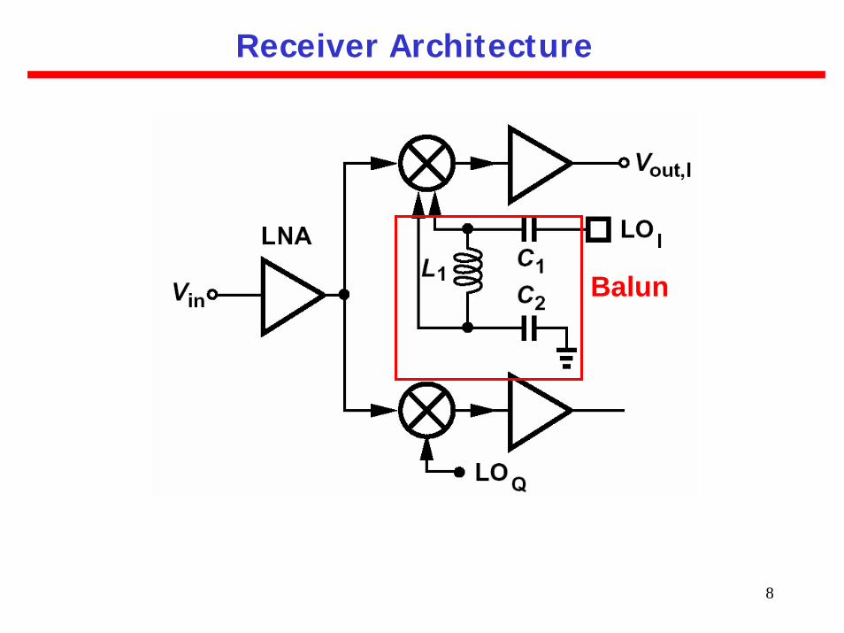
Receiver Architecture
Balun

9
Raw Speed of MOS Devices

10
Coplanar Line Microstrip Line
Spiral Inductors vs. Transmission Lines

11
Folded Microstrip

12
Choice of Linewidth

13
S
A
A'
Choice of Line Spacing

14
Choice of Line Spacing

15
Cascode vs. Common-Gate LNA

16
Simplified LNA

17
Complete LNA

18
Mixer Design
Conventional Mixer Proposed Mixer

19
On-Chip Balun

20
Receiver Floor Plan

21
Input
LO
BB
Out
put
Active Area = 300 um x 400 um
Die Photograph

22
Measured Performance

23
3-dB improvement in SNR for twice the power consumption and area.
Other Thoughts

24
Transmitter Front End
Slot Antenna- Large Area- High LossDipole- Narrow Footprint- Moderate Loss(~6 dB)

25
Transmitter Design
Pout = -10 dBm
Psupp = 44 mW

26
Nested Inductors

27
Effect of Mutual Coupling
168170172174176178180182184186188
-0.4 -0.3 -0.2 -0.1 0 0.1 0.2 0.3 0.4
Mutual Coupling (k)
Out
put V
olta
ge (m
V)

28
Die Photograph

29
Measurement Setup

30
Antenna Radiation Pattern
31
Flipflop-Based Dividers Miller DividerInjection-Locked Divider
Conventional Divider Topologies

32
Injection-Locked Divider
Narrow frequency range; inversely proportional to tank Q:
4π

33
Phase noise degrades if, due to mismatches, input frequency is not equal to 2ω0.
Phase Noise Degradation

34
Increasing the Range
[Rategh et al, JSSC, May 00]
Ganged tuning does not overcome frequency
mismatch.
Difficult to guarantee natural frequency of divider
tracks that of VCO.

35
Tracking Issues

36
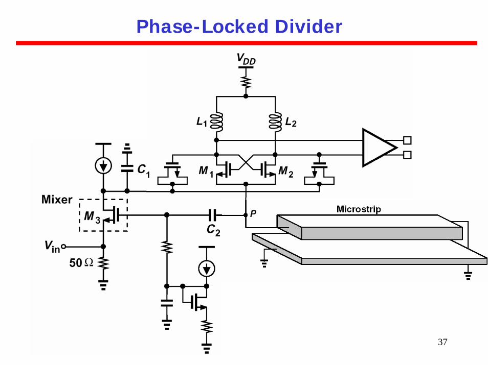
Phase-Locked Divider
Constant phase noise across range if gain of PD remains constant.No trade-off with tank Q. PD circuit must be very simple and experience complete switching.
37
Phase-Locked Divider

38
Die Photograph

39
Measured Output

40
Phase Noise across Range

41
Divider
Challenges Revisited
LO (I/Q) GenerationLO DivisionLO Distribution
LNA I/Q Mixers
QuadratureVCO

42
Conclusion
60-GHz transceivers can form highly-intercon-nected networks carrying high data rates. Nested inductors allow compact layout andshorter interconnects.Phase-locked dividers can provide a widefrequency range.Direct-conversion transceivers face difficultissues with respect to LO generation, division, and distribution.