6 stresses in soil mass
TRANSCRIPT

University of Anbar College of Engineering Civil Engineering Department Iraq-Ramadi
Asst. Prof. Khalid R. Mahmood (PhD.)
248
Stresses in a Soil Mass
Topics Normal and Shear Stresses on a Plane Stress distribution in soils Stress Caused by a Point Load Vertical Stress Caused by a Line Load Vertical Stress Caused by a Strip Load Vertical Stress Due to Embankment Loading Vertical Stress below the Center of a uniformly Loaded Circular Area Vertical Stress at any Point below a uniformly Loaded Circular Area Vertical Stress Caused by a Rectangularly Loaded Area Influence Chart for Vertical Pressure (Newmark Chart) Approximate methods
Added Stress
Geostatic Stress

University of Anbar College of Engineering Civil Engineering Department Iraq-Ramadi
Asst. Prof. Khalid R. Mahmood (PhD.)
249
Normal and Shear Stresses on a Plane
n, - n
M
x xy2
2
n, - n
N
T
M
n
n, - n
yx
yxM
xy
x
y
xy
xy
A B
C D
E
F
F
E B
Y > X

University of Anbar College of Engineering Civil Engineering Department Iraq-Ramadi
Asst. Prof. Khalid R. Mahmood (PhD.)
250
From geometry for the free body diagram EBF
sin
cos
EFFB
EFEB
Summing forces in N and T direction, we have cossin)(2cos)(sin)()( 22 EFEFEFEF xyyxn
2sin2cos22 xy
xyxyn …………………………..……….(1)
Again 22 sin)(cos)(cossin)(cossin)()( EFEFEFEFEF xyxyyxn
2cos2sin2 xy
xyn ……………………………………(2)
University of Anbar College of Engineering Civil Engineering Department Iraq-Ramadi
Asst. Prof. Khalid R. Mahmood (PhD.)
251
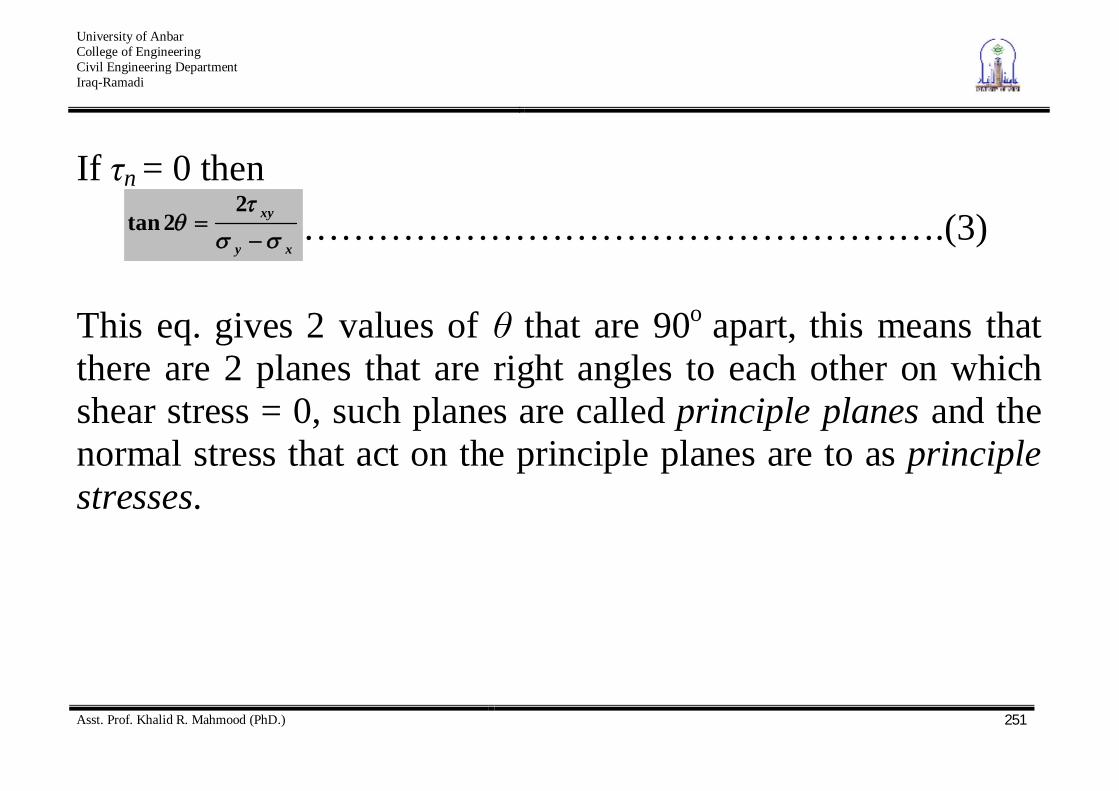
If n = 0 then
xy
xy22tan …………………………………………….(3)
This eq. gives 2 values of that are 90o apart, this means that there are 2 planes that are right angles to each other on which shear stress = 0, such planes are called principle planes and the normal stress that act on the principle planes are to as principle stresses.

University of Anbar College of Engineering Civil Engineering Department Iraq-Ramadi
Asst. Prof. Khalid R. Mahmood (PhD.)
252
To find the principle stress substitute eq.3 into eq.1, we get
stressprincipleor
stressprinciplemajor
xyxyxy
n
xyxyxy
n
min22
22
22
3
22
1
These stresses on any plane can be found using Mohr’s circle
University of Anbar College of Engineering Civil Engineering Department Iraq-Ramadi
Asst. Prof. Khalid R. Mahmood (PhD.)
253
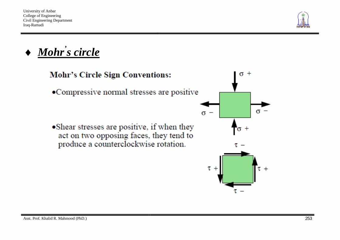
Mohr’s circle

University of Anbar College of Engineering Civil Engineering Department Iraq-Ramadi
Asst. Prof. Khalid R. Mahmood (PhD.)
254
Refer to the element shown in Fig. above

University of Anbar College of Engineering Civil Engineering Department Iraq-Ramadi
Asst. Prof. Khalid R. Mahmood (PhD.)
255
Pole Method
x, +
x
Pole
x
n 1 3
-
y
y,- xy
y
+
n, n
y
y
x x
xy
yx
yx
xy
A B
C
E

University of Anbar College of Engineering Civil Engineering Department Iraq-Ramadi
Asst. Prof. Khalid R. Mahmood (PhD.)
256
Geostatic stresses
Total Stress Effective Stress
Pore Water Pressure
Total Stress= Effective Stress+ Pore Water Pressure
Bossinisque Equations
•Point Load
•Line Load
•Strip Load
•Triangular Load
•Circular Load
•Rectangular Load
Added Stresses (Point, line, strip, triangular, circular, rectangular)
Stress Distribution in Soils
Influence Charts Newmark Charts Stress Bulbs
Westergaard’s Method
Approximate Method
A
Added
Geostatic
x
y
xy

University of Anbar College of Engineering Civil Engineering Department Iraq-Ramadi
Asst. Prof. Khalid R. Mahmood (PhD.)
257
Geostatic stresses The vertical geostatic stress at point X will be computed as following
hV homogenous soils
n
iiV h1
stratified soils h
v dz0
density varies continuously with depth

University of Anbar College of Engineering Civil Engineering Department Iraq-Ramadi
Asst. Prof. Khalid R. Mahmood (PhD.)
258
The horizontal geostatic stress can be computed as following
vh K where K is the coefficient of lateral stress or lateral stress
ratio
v
hK 11 K
Geostatic stress are principle stresses ( 1, 2 and 3 major, intermediate and minor principle stresses) and hence the horizontal and vertical planes through any point are principle planes.

University of Anbar College of Engineering Civil Engineering Department Iraq-Ramadi
Asst. Prof. Khalid R. Mahmood (PhD.)
259
1K 1v 3h h32 1K 321hv Isotropic 1K 1h 3v h12
The largest shear stress will found on plane lying at 45o to the horizontal
1K )1(2max Kv
1K 0max
1K )1(2max Kv

University of Anbar College of Engineering Civil Engineering Department Iraq-Ramadi
Asst. Prof. Khalid R. Mahmood (PhD.)
260
Stress Caused by a Point Load
GROUND
SURFACE
Z
Y
X
h
= v
General
Stresses Principal
Stresses
z = (3P/2 (Z3/L5) Boussinesq’s Equation
L=(x2+y2+z2)1/2=(r2+z2)1/2
z = 1
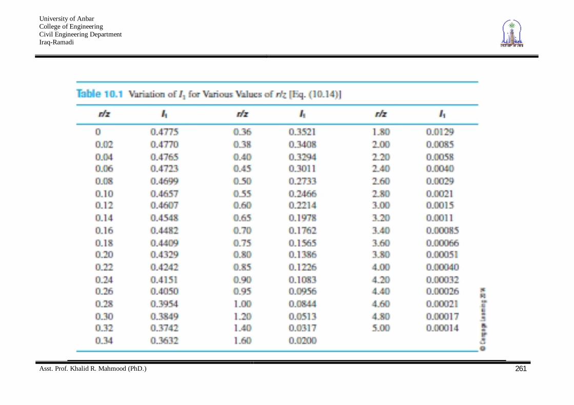
Using Influence Factor Tablebelow
z = (P/Z2) Ip
P
r=(x2+y2)1/2
University of Anbar College of Engineering Civil Engineering Department Iraq-Ramadi
Asst. Prof. Khalid R. Mahmood (PhD.)
261

University of Anbar College of Engineering Civil Engineering Department Iraq-Ramadi
Asst. Prof. Khalid R. Mahmood (PhD.)
262
Vertical Stress Caused by a Line Load
Z
X
Z
h
z
General
Stresses Principal
Stresses
X
Z
WALL
q (Load/Unit Length) q (Load/Unit Length)
Y
z = {2 q Z3/ XUsing Influence Factor Table below
z = (q/Z) IL

University of Anbar College of Engineering Civil Engineering Department Iraq-Ramadi
Asst. Prof. Khalid R. Mahmood (PhD.)
263

University of Anbar College of Engineering Civil Engineering Department Iraq-Ramadi
Asst. Prof. Khalid R. Mahmood (PhD.)
264
Vertical Stress Caused by a Strip Load
Z
X
Z
h
z
General
Stresses Principal
Stresses
Strip footing
Y
Using Influence Factor Tablebelow
z = (q/Z) IB
B q (Load/Unit Area)

University of Anbar College of Engineering Civil Engineering Department Iraq-Ramadi
Asst. Prof. Khalid R. Mahmood (PhD.)
265

University of Anbar College of Engineering Civil Engineering Department Iraq-Ramadi
Asst. Prof. Khalid R. Mahmood (PhD.)
266
Vertical Stress Due to Embankment Loading
Z
X
Z
h
v
General Highway embankment
EMBANKMENT
z = q/ 2)]
B2 B1 B1 B2
H
q= H
1(radians)=tan-1{(B1+B2)/z}-tan-1(B1/z)
2=tan-1(B1/z)
Using Influence Factor fig.(9.11-pp238)
z = qI2
Principal
1 2

University of Anbar College of Engineering Civil Engineering Department Iraq-Ramadi
Asst. Prof. Khalid R. Mahmood (PhD.)
267

University of Anbar College of Engineering Civil Engineering Department Iraq-Ramadi
Asst. Prof. Khalid R. Mahmood (PhD.)
268
Vertical Stress below the Center of a uniformly Loaded Circular Area
Qo X
Z
GROUND
SURFACE
Z
Y
Z
Principle
q
X
z= q { 1- 1/[(R/Z)2 + 1 ]3/2 }
z = qIc
Using Influence Factorfrom table.

University of Anbar College of Engineering Civil Engineering Department Iraq-Ramadi
Asst. Prof. Khalid R. Mahmood (PhD.)
269
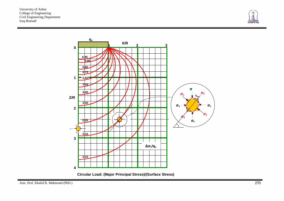
Vertical Stress at any Point below a uniformly Loaded Circular Area
Or we can use the stress bulb charts
Qo X
Z
GROUND
SURFACE
Z
Y
Z
h
z v
General
Stresses
q
X
z= q (A/+B/)
r
Where (A/&B/) are functions of z/R and r/R
from tables
University of Anbar College of Engineering Civil Engineering Department Iraq-Ramadi
Asst. Prof. Khalid R. Mahmood (PhD.)
270
x
z
x
xy
2
1
1
2
X/R
Z/R
0.95
1
2
3
4
1 2 3 0
0.90
0.80
0.70
0.30
0.50
0.40
0.10
0.20
0.15
qs
1/qs
0.60
x x
xy
Circular Load: (Major Principal Stress)/(Surface Stress)
z =
z =
x = x =

University of Anbar College of Engineering Civil Engineering Department Iraq-Ramadi
Asst. Prof. Khalid R. Mahmood (PhD.)
271
X/R
Z/R
0.40
1
2
3
4
1 2 3 0
0.55
0.60
0.55
0.30
0.45
0.40
0.10
0.20
0.15
1 3)/qs
0.50
0.50
0.60
0.35
0.25
qs
z = 1
z = 1
x = 2 x = 2

University of Anbar College of Engineering Civil Engineering Department Iraq-Ramadi
Asst. Prof. Khalid R. Mahmood (PhD.)
272
X/R
Z/R
1
2
3
4
1 2 3 0
0.90
0.80
0.70
0.30
0.50
0.40
0.10
0.20
qs
z/qs
0.60
Circular Load: (Vertical Stress)/(Surface
0.05
z =
z =
x = 2 x =
0.15

University of Anbar College of Engineering Civil Engineering Department Iraq-Ramadi
Asst. Prof. Khalid R. Mahmood (PhD.)
273
Vertical Stress Caused by a Rectangularly Loaded Area
from tables or one can use the charts below
h
z v
Z
L
B q = Load /Area
IR = f (m,n)
m = B/Z
n = L/Z m & n from Charts or tables
Loaded Area Foundation Level
IR = 1/4 {[ (2. m.n (m2 + n2 + 1)1/2 ) / (m2 + n2 + m2. n2 + 1) ] [(m2 + n2 + 2)/(m2 + n2 + 1)] +tan-1 (2.m .n (m2 + n2 + 1)1/2 / (m2 + n2 - m2 . n2 + 1)}
B
P = q IR
Corner of the Building X
L

University of Anbar College of Engineering Civil Engineering Department Iraq-Ramadi
Asst. Prof. Khalid R. Mahmood (PhD.)
274

University of Anbar College of Engineering Civil Engineering Department Iraq-Ramadi
Asst. Prof. Khalid R. Mahmood (PhD.)
275
Calculation of Stress below an interior point of the loaded area
)()()()([ OTDXIOZCTIOYBZIOXAYIqz
O P o in t o f in t e r e s t
O
A B
D C
X
Y
Z
T
F i g . 1 0 s t r e s s i n c r e a s e a t a p o i n t b e l o w a l o a d e d r e c t a n g u l a r r e g i o n
z
Q = q x Area
Plan
Elevation
University of Anbar College of Engineering Civil Engineering Department Iraq-Ramadi
Asst. Prof. Khalid R. Mahmood (PhD.)
276
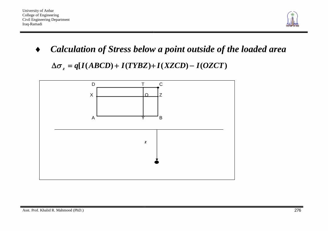
Calculation of Stress below a point outside of the loaded area
)()()()([ OZCTIXZCDITYBZIABCDIqz
O P o in t o f in te r e s t
O
A B
D C
X
Y
Z
T
F ig . 1 0 s t r e s s in c r e a s e a t a p o in t b e lo w a l o a d e d r e c t a n g u la r r e g io n
z
z

University of Anbar College of Engineering Civil Engineering Department Iraq-Ramadi
Asst. Prof. Khalid R. Mahmood (PhD.)
277
Influence Chart for Vertical Pressure (Newmark Chart) Stresses due to foundation loads of arbitrary shape applied at
the ground surface Newmark’s chart provides a graphical method for calculating the stress increase due to a uniformly loaded region, of arbitrary shape resting on a deep homogeneous isotropic elastic region. Newmark’s chart is given in the data sheets and is reproduced in part in Fig 15. The procedure for its use is outlined below 1.The scale for this procedure is determined by the depth z at
which the stress is to be evaluated, thus z is equal to the distance OQ shown on the chart.

University of Anbar College of Engineering Civil Engineering Department Iraq-Ramadi
Asst. Prof. Khalid R. Mahmood (PhD.)
278
2.Draw the loaded area to scale so that the point of interest (more correctly its vertical projection on the surface) is at the origin of the chart, the orientation of the drawing does not matter
3.Count the number of squares (N) within the loaded area, if more than half the square is in count the square otherwise neglect it.
4.The vertical stress increase z = N [scale factor(0.001)] [surface stress (p)]

University of Anbar College of Engineering Civil Engineering Department Iraq-Ramadi
Asst. Prof. Khalid R. Mahmood (PhD.)
279
O Q4m
LoadedArea

University of Anbar College of Engineering Civil Engineering Department Iraq-Ramadi
Asst. Prof. Khalid R. Mahmood (PhD.)
280
Approximate Methods Equivalent Point Load Method
In dividing the loaded area into smaller units, we have to remember to do it such that z/B 3; that is to say, in relation to the specified depth, the size of any unit area should not be greater than one-third of the depth.
pii
z IzQ
2

University of Anbar College of Engineering Civil Engineering Department Iraq-Ramadi
Asst. Prof. Khalid R. Mahmood (PhD.)
281
Each Q is the resultant of the uniform load on the unit area acts at the center of it and treated as a point load

University of Anbar College of Engineering Civil Engineering Department Iraq-Ramadi
Asst. Prof. Khalid R. Mahmood (PhD.)
282
2:1 Method
))(( ZLZBQ
z Rectangular area
2)( ZBQ
z Square area
2)(4
ZD
Qz Circular area

University of Anbar College of Engineering Civil Engineering Department Iraq-Ramadi
Asst. Prof. Khalid R. Mahmood (PhD.)
283
Examples (1-3)

University of Anbar College of Engineering Civil Engineering Department Iraq-Ramadi
Asst. Prof. Khalid R. Mahmood (PhD.)
284

University of Anbar College of Engineering Civil Engineering Department Iraq-Ramadi
Asst. Prof. Khalid R. Mahmood (PhD.)
285

University of Anbar College of Engineering Civil Engineering Department Iraq-Ramadi
Asst. Prof. Khalid R. Mahmood (PhD.)
286
Example 4 A rectangular foundation 6 x 3m carries a uniform pressure of 300 kN/m2 near the surface of a soil mass. Determine the vertical stress at a depth of 3m below a point (A) on the centre line 1.5m outside a long edge of the foundation using influence factors
m = 1 m=1
n =1.5 n=0.5
I = 0.193 I=0.120

University of Anbar College of Engineering Civil Engineering Department Iraq-Ramadi
Asst. Prof. Khalid R. Mahmood (PhD.)
287
Example 5 Determine the stress increase under the embankment at points A1 and A2

University of Anbar College of Engineering Civil Engineering Department Iraq-Ramadi
Asst. Prof. Khalid R. Mahmood (PhD.)
288

University of Anbar College of Engineering Civil Engineering Department Iraq-Ramadi
Asst. Prof. Khalid R. Mahmood (PhD.)
289