6 fs series safety switches with separate actuator with lock
TRANSCRIPT
6
137
0,5 ... 5 mm
General Catalogue Safety 2021-2022
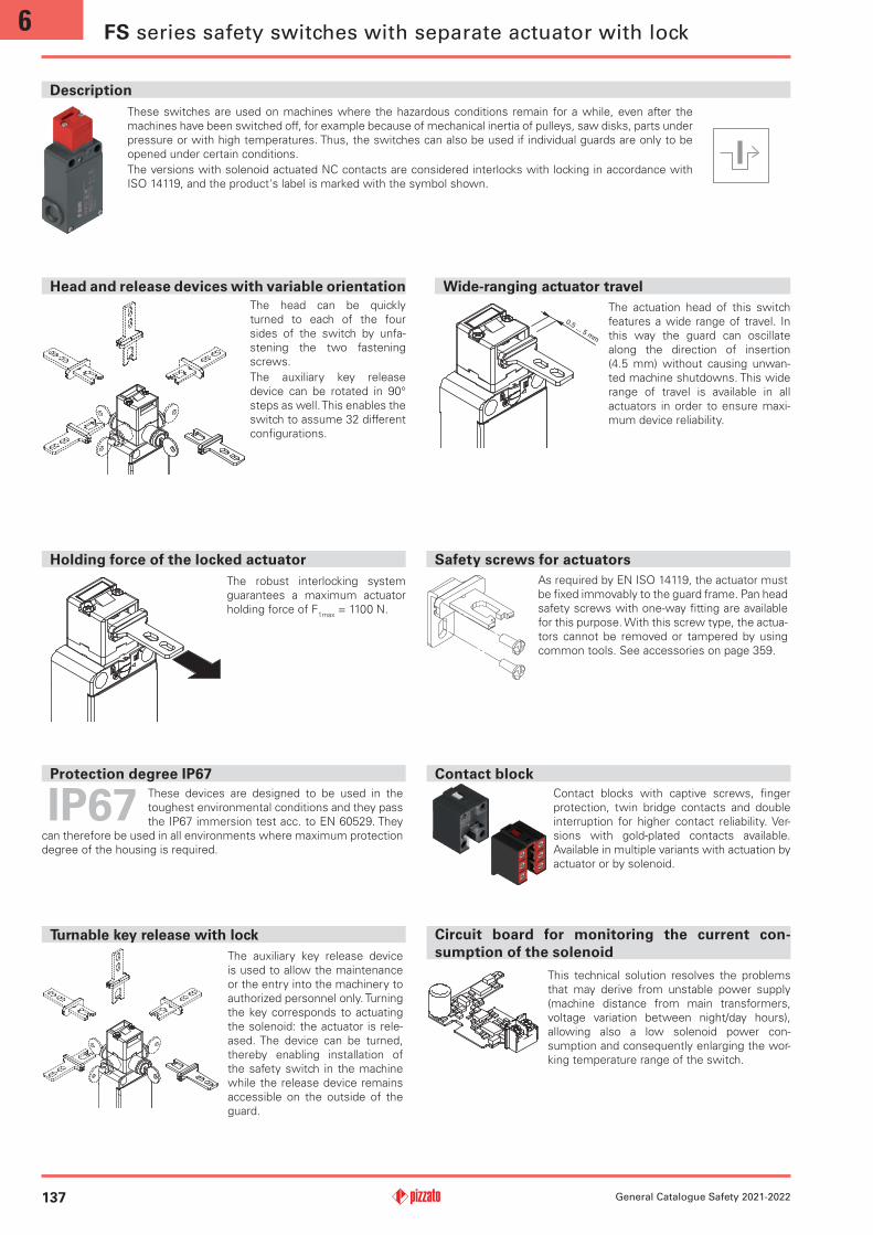
Safety screws for actuatorsHolding force of the locked actuator
Head and release devices with variable orientation Wide-ranging actuator travel
As required by EN ISO 14119, the actuator must
be fixed immovably to the guard frame. Pan head
safety screws with one-way fitting are available
for this purpose. With this screw type, the actua-
tors cannot be removed or tampered by using
common tools. See accessories on page 359.
Description
These devices are designed to be used in the
toughest environmental conditions and they pass
the IP67 immersion test acc. to EN 60529. They
can therefore be used in all environments where maximum protection
degree of the housing is required.
Protection degree IP67 Contact block
This technical solution resolves the problems
that may derive from unstable power supply
(machine distance from main transformers,
voltage variation between night/day hours),
allowing also a low solenoid power con-
sumption and consequently enlarging the wor-
king temperature range of the switch.
Circuit board for monitoring the current con-
sumption of the solenoid
These switches are used on machines where the hazardous conditions remain for a while, even after the
machines have been switched off, for example because of mechanical inertia of pulleys, saw disks, parts under
pressure or with high temperatures. Thus, the switches can also be used if individual guards are only to be
opened under certain conditions.
The versions with solenoid actuated NC contacts are considered interlocks with locking in accordance with
ISO 14119, and the product's label is marked with the symbol shown.
The auxiliary key release device
is used to allow the maintenance
or the entry into the machinery to
authorized personnel only. Turning
the key corresponds to actuating
the solenoid: the actuator is rele-
ased. The device can be turned,
thereby enabling installation of
the safety switch in the machine
while the release device remains
accessible on the outside of the
guard.
Turnable key release with lock
FS series safety switches with separate actuator with lock
Contact blocks with captive screws, finger
protection, twin bridge contacts and double
interruption for higher contact reliability. Ver-
sions with gold-plated contacts available.
Available in multiple variants with actuation by
actuator or by solenoid.
The robust interlocking system
guarantees a maximum actuator
holding force of F1max
= 1100 N.
The head can be quickly
turned to each of the four
sides of the switch by unfa-
stening the two fastening
screws.
The auxiliary key release
device can be rotated in 90°
steps as well. This enables the
switch to assume 32 different
configurations.
The actuation head of this switch
features a wide range of travel. In
this way the guard can oscillate
along the direction of insertion
(4.5 mm) without causing unwan-
ted machine shutdowns. This wide
range of travel is available in all
actuators in order to ensure maxi-
mum device reliability.

6
138General Catalogue Safety 2021-2022
Laser engraving
All FS series switches are permanently marked with a special laser system. As a result, the marking remains legible even under extreme operating conditions. Thanks to this system that does not use labels, the loss of plate data is prevented and a greater resistance of the marking is achieved over time.
Holding force of the unlocked actuator
Two operating principles
The safety switches with solenoid offer two
different operating principles for the actuator
locking:
Operating principle D: locked actuator with
de-energised solenoid. The actuator is released by applying the power
supply to the solenoid.
Operating principle E: locked actuator with energised solenoid. The
actuator is released by switching off the power supply to the solenoid.
This version should only be used under certain conditions, since a
power failure at the system will result in the immediate opening of
the guard.
Sealable auxiliary release device
Switches with locked actuator
with deactivated solenoid (fun-
ction principle D) are equip-
ped with an auxiliary release
device for the solenoid to sim-
plify installation of the switch
and to facilitate entry into the
danger zone in the event of
a power failure. The auxiliary
release device acts on the switch exactly as if the solenoid was ener-
gised. As a result, it also actuates the electrical contacts. Can only be
actuated with a couple of tools, this ensures adequate resistance to
tampering. If required it can be sealed by means of the hole provided.
Cable outlets
The switch is provided with three cable entries
in different directions. This allows its application
in series connections or in narrow places.
The contact blocks of these devices can be sup-plied gold-plated upon request. Ideal for applica-tions with low voltages or currents; it ensures
increased contact reliability. Available in two
thicknesses (1 or 2.5 microns), it adapts perfectly
to the various fields of application, ensuring a
long endurance over time.
Gold-plated contacts
LED signalling lights
Thanks to the three threaded cable entries,
the high luminosity LED signalling lights of the
VF SL series can be installed on the switch.
The LED signalling lights can be be easily instal-
led by screwing them on one of the conduit
entries not used for electric cables. They can be
used for many different purposes: for example,
to signal, from a distance, whether the switch
has been actuated; whether the guard has
closed correctly; or whether the guard is locked
or unlocked.
For more information see chapter Accessories,
page 359.
The inside of each switch features
a device which holds the actuator
in its closed position. Ideal for all
those applications where seve-
ral guards are unlocked simulta-
neously, but only one is actually
opened. The device keeps all the
unlocked guards in their position
with a retaining force of approx.
30 N, stopping any vibrations or
gusts of wind from opening them.
6
139
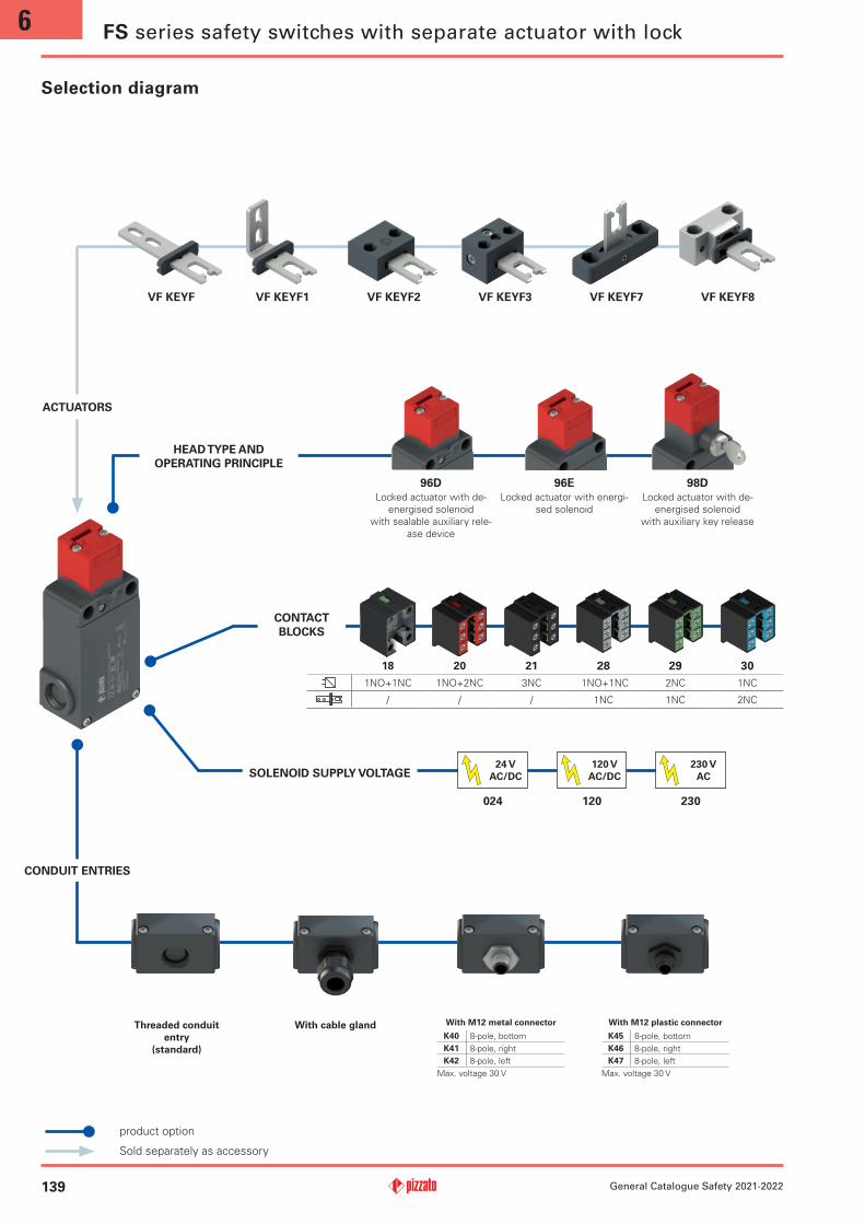
96D 96E 98D
24 V
AC/DC
120 V
AC/DC
230 V
AC
024 120 230
VF KEYF VF KEYF1 VF KEYF2 VF KEYF3 VF KEYF7 VF KEYF8
18 20 21 28 29 30
1NO+1NC 1NO+2NC 3NC 1NO+1NC 2NC 1NC
/ / / 1NC 1NC 2NC
General Catalogue Safety 2021-2022
Locked actuator with de-
energised solenoid
with sealable auxiliary rele-
ase device
Locked actuator with energi-
sed solenoid
Locked actuator with de-
energised solenoid
with auxiliary key release
Selection diagram
Threaded conduit
entry
(standard)
With cable gland
ACTUATORS
CONTACT
BLOCKS
CONDUIT ENTRIES
HEAD TYPE AND
OPERATING PRINCIPLE
SOLENOID SUPPLY VOLTAGE
With M12 metal connector
K40 8-pole, bottom
K41 8-pole, right
K42 8-pole, left
Max. voltage 30 V
With M12 plastic connector
K45 8-pole, bottom
K46 8-pole, right
K47 8-pole, left
Max. voltage 30 V
FS series safety switches with separate actuator with lock
product option
Sold separately as accessory
6
140
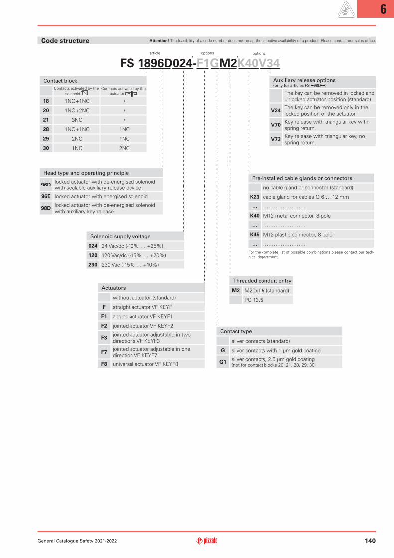
FS 1896D024-F1GM2K40V34
General Catalogue Safety 2021-2022
Code structure
Contact block
Contacts activated by the
solenoid
Contacts activated by the
actuator
18 1NO+1NC /
20 1NO+2NC /
21 3NC /
28 1NO+1NC 1NC
29 2NC 1NC
30 1NC 2NC
Threaded conduit entry
M2 M20x1.5 (standard)
PG 13.5
Head type and operating principle
96Dlocked actuator with de-energised solenoid
with sealable auxiliary release device
96E locked actuator with energised solenoid
98Dlocked actuator with de-energised solenoid
with auxiliary key release
Actuators
without actuator (standard)
F straight actuator VF KEYF
F1 angled actuator VF KEYF1
F2 jointed actuator VF KEYF2
F3jointed actuator adjustable in two
directions VF KEYF3
F7jointed actuator adjustable in one
direction VF KEYF7
F8 universal actuator VF KEYF8
Solenoid supply voltage
024 24 Vac/dc (-10% … +25%).
120 120 Vac/dc (-15% … +20%)
230 230 Vac (-15% … +10%)
article options
Pre-installed cable glands or connectors
no cable gland or connector (standard)
K23 cable gland for cables Ø 6 … 12 mm
… ……………………
K40 M12 metal connector, 8-pole
… ……………………
K45 M12 plastic connector, 8-pole
… ……………………
For the complete list of possible combinations please contact our tech-
nical department.
options
Contact type
silver contacts (standard)
G silver contacts with 1 µm gold coating
G1silver contacts, 2.5 µm gold coating (not for contact blocks 20, 21, 28, 29, 30)
Auxiliary release options (onlyforarticlesFS••98D•••)
The key can be removed in locked and
unlocked actuator position (standard)
V34The key can be removed only in the
locked position of the actuator
V70Key release with triangular key with
spring return.
V73Key release with triangular key, no
spring return.
Attention! The feasibility of a code number does not mean the effective availability of a product. Please contact our sales office.

6
141 General Catalogue Safety 2021-2022
General dataSIL (SIL CL) up to: SIL 3 acc. to EN 62061
PL e acc. to EN ISO 13849-1Performance Level (PL) up to:
Interlock with mechanical lock, coded: type 2 acc. to EN ISO 14119
Coding level: low acc. to EN ISO 14119
Safety parameters:
B10D
: 4,000,000 for NC contacts
Mission time: 20 years
Ambient temperature: -25°C ... +60°C
Max. actuation frequency: 600 operating cycles/hour
Mechanical endurance: 800,000 operating cycles
Max. actuation speed: 0.5 m/s
Min. actuation speed: 1 mm/s
Maximum force before breakage F1max
: 1100 N (head 96), 900 N (head 98)
acc. to EN ISO 14119
Max. holding force FZh
: 846 N (head 96), 692 N (head 98)
acc. to EN ISO 14119
Maximum clearance of locked actuator: 4.5 mm
Released actuator extraction force: 30 N
Tightening torques for installation: see page 379
Wire cross-sections and
wire stripping lengths: see page 399
SolenoidDuty cycle: 100% ED (continuous operation)
Solenoid inrush power: 20 VA 0.1 s (24 V)
18 VA 0,1 s (120 V)
18 VA 0,1 s (230 V)
Solenoid consumption: 4 VA
Average overall consumption: 10 VA
Solenoid protection 24 V: fuse 500 mA, delayed
Solenoid protection 120 V: fuse 315 mA, delayed
Solenoid protection 230 V: fuse 160 mA, delayed
Notes: Calculate the power supply using the average overall consumption. Please con-sider the solenoid inrush power in order to avoid intervention of overload-protection in case of electronic power supply.
Electrical data Utilization category
Alternating current: AC15 (50÷60 Hz)
Ue (V) 250 400 500
Ie (A) 6 4 1
Direct current: DC13
Ue (V) 24 125 250
Ie (A) 3 0.55 0.3
Thermal current (Ith): 2 A
Rated insulation voltage (Ui): 30 Vac 36 Vdc
Protection against short circuits: type gG fuse 2 A 500 V
Pollution degree: 3
with M
12 c
on-
necto
r, 8
-pole
Alternating current: AC15 (50÷60 Hz)
Ue (V) 24
Ie (A) 2
Direct current: DC13
Ue (V) 24
Ie (A) 2
without
connecto
r
HousingHousing made of glass fibre reinforced technopolymer, self-extinguishing, shock-proof and with double insulation: Three knock-out threaded conduit entries: M20x1.5 (standard)
Protection degree: IP67 acc. to EN 60529 with cable gland of equal or higher protection degree
Main features
•Technopolymer housing, three conduit entries
•Protection degree IP67
•6 contact blocks available
•6 stainless steel actuators available
•3 solenoid supply voltages available
•Versions with auxiliary release device or turnable lock
•Operation with energised or de-energised solenoid
FS series safety switches with separate actuator with lock
Quality marks:
IMQ approval: CA02.03808
UL approval: E131787
CCC approval: 2020970305002281
EAC approval: RUC-IT.УT03.В.00035/19
In compliance with standards:IEC 60947-5-1, IEC 60947-1, IEC 60204-1, EN ISO 14119, EN ISO 12100, IEC 60529, IEC 61000-6-2, IEC 61000-6-3, EN IEC 63000, BG-GS-ET-15, UL 508, CSA 22.2 N. 14.Approvals:
EN 60947-5-1, UL 508, CSA 22.2 N. 14, GB/T14048.5
If not expressly indicated in this chapter, for correct installation and utilization of all articles see the instructions given on pages
377 to 392.
Thermal current (Ith): 10 A
Rated insulation voltage (Ui): 500 Vac 600 Vdc
400 Vac 500 Vdc (contact blocks 20, 21, 28, 29, 30)Rated impulse withstand voltage (U
imp): 6 kV
4 kV (contact blocks 20, 21, 28, 29, 30)
Conditional short circuit current: 1000 A acc. to EN 60947-5-1Protection against short circuits: type aM fuse 10 A 500 VPollution degree: 3
Compliance with the requirements of:
Machinery Directive 2006/42/EC, EMC Directive 2014/30/EU, RoHS Directive 2011/65/EU.
Positive contact opening in conformity with standards:
IEC 60947-5-1, EN 60947-5-1.
Technical data
6
142
Electrical Ratings: Q300 pilot duty (69 VA, 125-250 V dc)
A600 pilot duty (720 VA, 120-600 V ac)
Environmental Ratings: Types 1, 4X, 12, 13
Use 60 or 75 °C copper (Cu) conductor and wire size range 12, 14 AWG,
stranded or solid. The terminal tightening torque of 7.1 lb in (0.8 Nm).
1
2
34
5
6
7
8
1
2
34
5
6
7
8
1
2
34
5
6
7
8
1
2
34
5
6
7
8
1
2
34
5
6
7
8
1
2
34
5
6
7
8
General Catalogue Safety 2021-2022
Please contact our technical department for the list of approved products.
Please contact our technical department for the list of approved products.
Features approved by UL
Rated insulation voltage (Ui): 500 Vac400 Vac (for contact blocks 20, 21, 28, 29, 30)
Conventional free air thermal current (I
th):
10 A
Protection against short circuits: type aM fuse 10 A 500 VRated impulse withstand voltage (U
imp): 6 kV
4 kV (for contact blocks 20, 21, 28, 29, 30)
Protection degree of the housing: IP67MV terminals (screw terminals)Pollution degree: 3Utilization category: AC15Operating voltage (U
e): 400 Vac (50 Hz)
Operating current (Ie): 3 A
Forms of the contact element: Zb, Y+Y+X, Y+Y+Y, Y+X+X
Positive opening contacts on contact blocks 18, 20, 21, 28, 29, 30
In compliance with standards: EN 60947-1, EN 60947-5-1, fundamental requirements of the Low Voltage Directive 2014/35/EU.
Features approved by IMQ
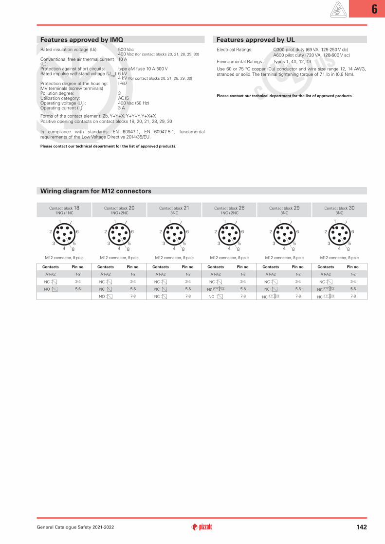
Wiring diagram for M12 connectors
Contact block 181NO+1NC
Contact block 201NO+2NC
Contact block 213NC
Contact block 281NO+2NC
Contact block 293NC
Contact block 303NC
M12 connector, 8-pole M12 connector, 8-pole M12 connector, 8-pole M12 connector, 8-pole M12 connector, 8-pole M12 connector, 8-pole
Contacts Pin no. Contacts Pin no. Contacts Pin no. Contacts Pin no. Contacts Pin no. Contacts Pin no.
A1-A2 1-2 A1-A2 1-2 A1-A2 1-2 A1-A2 1-2 A1-A2 1-2 A1-A2 1-2
NC 3-4 NC 3-4 NC 3-4 NC 3-4 NC 3-4 NC 3-4
NO 5-6 NC 5-6 NC 5-6 NC 5-6 NC 5-6 NC 5-6
NO 7-8 NC 7-8 NO 7-8 NC 7-8 NC 7-8
6
143 General Catalogue Safety 2021-2022
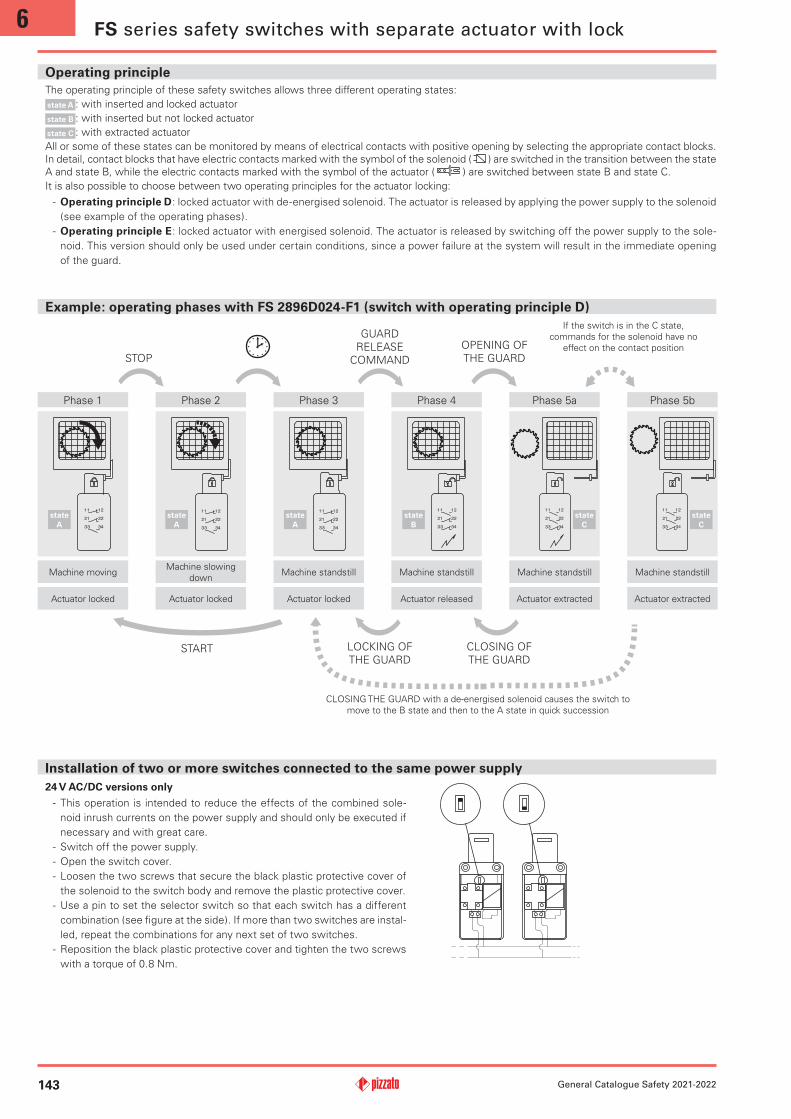
Example: operating phases with FS 2896D024-F1 (switch with operating principle D)
STOP
GUARD
RELEASE
COMMAND
OPENING OF
THE GUARD
CLOSING OF
THE GUARDSTART LOCKING OF
THE GUARD
CLOSING THE GUARD with a de-energised solenoid causes the switch to
move to the B state and then to the A state in quick succession
If the switch is in the C state,
commands for the solenoid have no
effect on the contact position
Phase 5a
Machine standstill
Actuator extracted
Phase 4
Machine standstill
Actuator released
Phase 2
Machine slowing
down
Actuator locked
Phase 1
Machine moving
Actuator locked
state
A
state
A
state
B
Phase 3
Machine standstill
Actuator locked
state
A
Phase 5b
Machine standstill
Actuator extracted
state
C
state
C
Installation of two or more switches connected to the same power supply
24 V AC/DC versions only
- This operation is intended to reduce the effects of the combined sole-
noid inrush currents on the power supply and should only be executed if
necessary and with great care.
- Switch off the power supply.
- Open the switch cover.
- Loosen the two screws that secure the black plastic protective cover of
the solenoid to the switch body and remove the plastic protective cover.
- Use a pin to set the selector switch so that each switch has a different
combination (see figure at the side). If more than two switches are instal-
led, repeat the combinations for any next set of two switches.
- Reposition the black plastic protective cover and tighten the two screws
with a torque of 0.8 Nm.
The operating principle of these safety switches allows three different operating states:
state A : with inserted and locked actuator
state B : with inserted but not locked actuator
state C : with extracted actuator
All or some of these states can be monitored by means of electrical contacts with positive opening by selecting the appropriate contact blocks.
In detail, contact blocks that have electric contacts marked with the symbol of the solenoid ( ) are switched in the transition between the state
A and state B, while the electric contacts marked with the symbol of the actuator ( ) are switched between state B and state C.
It is also possible to choose between two operating principles for the actuator locking:
- Operating principle D: locked actuator with de-energised solenoid. The actuator is released by applying the power supply to the solenoid
(see example of the operating phases).
- Operating principle E: locked actuator with energised solenoid. The actuator is released by switching off the power supply to the sole-
noid. This version should only be used under certain conditions, since a power failure at the system will result in the immediate opening
of the guard.
Operating principle
FS series safety switches with separate actuator with lock
6
144
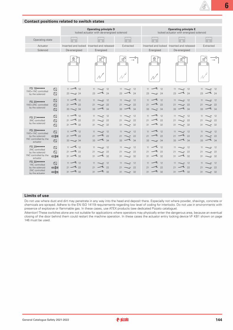
11 12 11 12 11 12 11 12 11 12 11 12
23 24 23 24 23 24 23 24 23 24 23 24
11 12 11 12 11 12 11 12 11 12 11 12
21 22 21 22 21 22 21 22 21 22 21 22
33 34 33 34 33 34 33 34 33 34 33 34
11 12 11 12 11 12 11 12 11 12 11 12
21 22 21 22 21 22 21 22 21 22 21 22
31 32 31 32 31 32 31 32 31 32 31 32
11 12 11 12 11 12 11 12 11 12 11 12
21 22 21 22 21 22 21 22 21 22 21 22
33 34 33 34 33 34 33 34 33 34 33 34
11 12 11 12 11 12 11 12 11 12 11 12
21 22 21 22 21 22 21 22 21 22 21 22
31 32 31 32 31 32 31 32 31 32 31 32
11 12 11 12 11 12 11 12 11 12 11 12
21 22 21 22 21 22 21 22 21 22 21 22
31 32 31 32 31 32 31 32 31 32 31 32
General Catalogue Safety 2021-2022
Contact positions related to switch states
FS18••••••1NO+1NC controlled
by the solenoid
FS 20••••••1NO+2NC controlled
by the solenoid
FS 21••••••3NC controlled
by the solenoid
FS28••••••1NO+1NC controlled
by the solenoid
1NC controlled by the
actuator
FS29••••••2NC controlled
by the solenoid
1NC controlled by the
actuator
FS 30••••••1NC controlled
by the solenoid
2NC controlled
by the actuator
Operating principle D
locked actuator with de-energised solenoid
Operating principle E
locked actuator with energised solenoid
Operating statestate
A
state
B
state
C
state
A
state
B
state
C
Actuator Inserted and locked Inserted and released Extracted Inserted and locked Inserted and released Extracted
Solenoid De-energised Energised - Energised De-energised -
Limits of use
Do not use where dust and dirt may penetrate in any way into the head and deposit there. Especially not where powder, shavings, concrete or
chemicals are sprayed. Adhere to the EN ISO 14119 requirements regarding low level of coding for interlocks. Do not use in environments with
presence of explosive or flammable gas. In these cases, use ATEX products (see dedicated Pizzato catalogue).
Attention! These switches alone are not suitable for applications where operators may physically enter the dangerous area, because an eventual
closing of the door behind them could restart the machine operation. In these cases the actuator entry locking device VF KB1 shown on page
146 must be used.

6
145
18 L
20 L
21 L
28 L
29 L
30 L
30 N (40 N ) 30 N (40 N ) 30 N (40 N )
5.5
3592
4313
5
3.4 56 3.4
32
40
8
19.4
15
38.2
5.5
3592
4313
5
3.4 56 3.4
32
40
8
19.4
15
38.2
848
.5
32
40
62.8
92
5.5
8
15
38.2
76.1
25.318.2
19.4
11-12
33-34
21-22
0 9 9.5
FS1896D024-M2 1NO+1NC
11-1223-24
FS2096D024-M2 1NO+2NC
11-1221-2233-34
FS2196D024-M2 3NC
11-1221-2231-32
FS2896D024-M2 1NO+2NC
0
11-1233-34
21-22
9 10
FS2996D024-M2 3NC
0 9 10
11-1221-22
31-32
FS3096D024-M2 3NC
0 9 10
11-12
21-2231-32
FS1898D024-M2 1NO+1NC
11-1223-24
FS2098D024-M2 1NO+2NC
11-1221-2233-34
FS2198D024-M2 3NC
11-1221-2231-32
FS2898D024-M2 1NO+2NC
0
11-1233-34
21-22
9 10
FS2998D024-M2 3NC
0 9 10
11-1221-22
31-32
FS3098D024-M2 3NC
0 9 10
11-12
21-2231-32
FS1896E024-M2 1NO+1NC
11-1223-24
FS2096E024-M2 1NO+2NC
11-1221-2233-34
FS2196E024-M2 3NC
11-1221-2231-32
FS2896E024-M2 1NO+2NC
0
11-1233-34
21-22
9 10
FS2996E024-M2 3NC
0 9 10
11-1221-22
31-32
FS3096E024-M2 3NC
0 9 10
11-12
21-2231-32
Ø 14
8
Ø 6,5
Ø 9,5
General Catalogue Safety 2021-2022
Contact type:
L = slow action
Contact block
Actuating force
How to read travel diagrams
NC opening
NO closing
Positive opening travel
Max. travel
of the actuator
NC opening
Contacts activated
by the actuator
Contacts activated
by the solenoid Closed contact
Open contact
IMPORTANT:
The state of the NC contact refers to the switch with
inserted actuator and locked lock. In safety applica-
tions, actuate the switch at least up to the positive
opening travel shown in the travel diagrams with
symbol . Actuate the switch at least with the posi-
tive opening force, reported in brackets below each
article, next to the actuating force value.
Auxiliary key release with triangular key
Legend: With positive opening according to EN 60947-5-1, interlock with lock monitoring acc. to EN ISO 14119
FS series safety switches with separate actuator with lock
Accessories See page 359 The 2D and 3D files are available at www.pizzato.comAll values in the drawings are in mm
Operating principle D, with sealable auxiliary
release device, without actuator Operating principle E, without actuator
Operating principle D, with auxiliary key
release, without actuator
Articles with the V70 and V73 option have an auxiliary key release with a triangular key that meets
DIN 22417 standards.
This type of lock can be used in situations where the switch must only be unlocked using the
corresponding triangular key, a tool which is not usually available.
There are two versions of the triangular key release: with a spring return (option V70) and without
a spring return (option V73).
6
146General Catalogue Safety 2021-2022
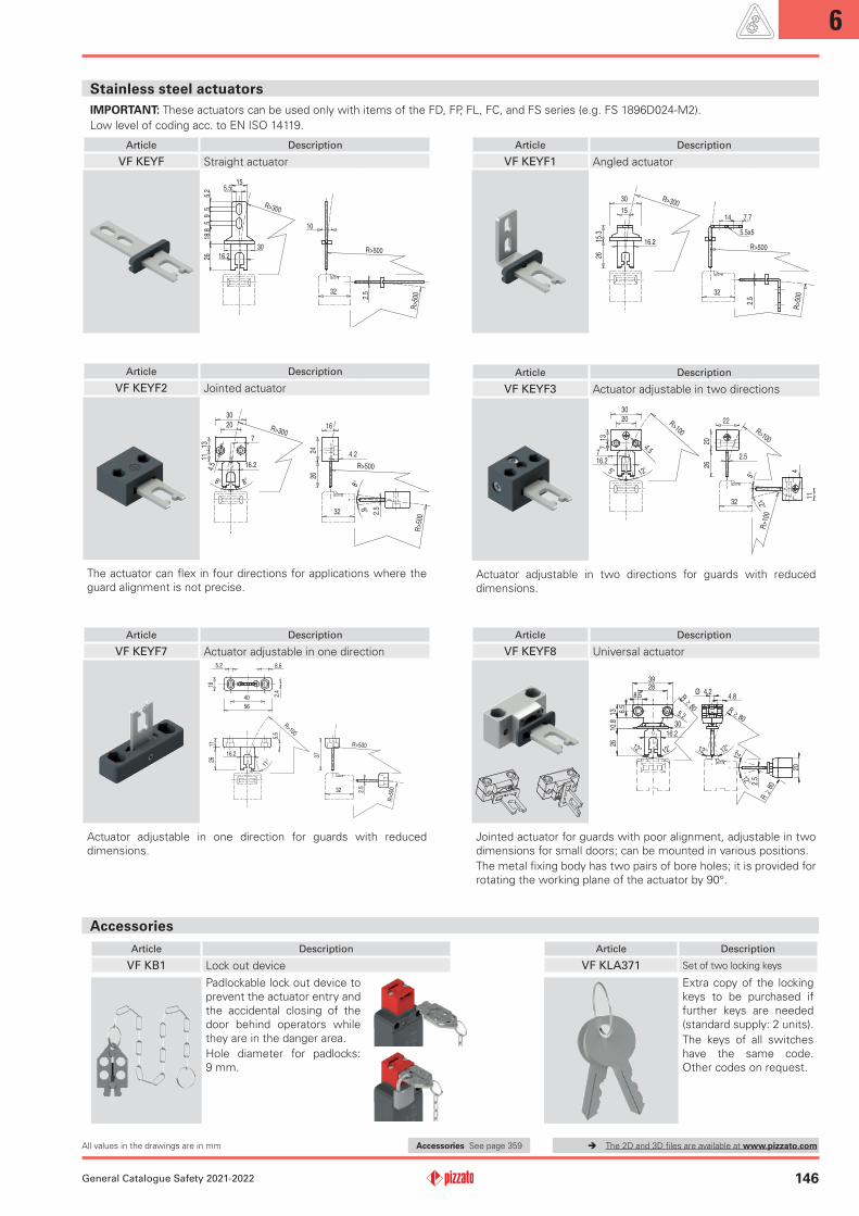
Accessories
IMPORTANT: These actuators can be used only with items of the FD, FP, FL, FC, and FS series (e.g. FS 1896D024-M2).
Low level of coding acc. to EN ISO 14119.
Stainless steel actuators
Article Description
VF KLA371 Set of two locking keys
Extra copy of the locking
keys to be purchased if
further keys are needed
(standard supply: 2 units).
The keys of all switches
have the same code.
Other codes on request.
Article Description
VF KB1 Lock out device
Padlockable lock out device to
prevent the actuator entry and
the accidental closing of the
door behind operators while
they are in the danger area.
Hole diameter for padlocks:
9 mm.
Article Description
VFKEYF2 Jointed actuator
32
30
13
20
114.
5
8° 8°
8°
8°
16
2426
R>300
R>500
R>5
00
2.5
16.2
7
4.2
The actuator can flex in four directions for applications where the
guard alignment is not precise.
Article Description
VFKEYF7 Actuator adjustable in one direction
32
1126
37
2.5
11°
40
56
16
8.65.2
2.4
R>100
R>5
00
R>500
16.2
5.5
Actuator adjustable in one direction for guards with reduced
dimensions.
Article Description
VFKEYF3 Actuator adjustable in two directions
32
13
20
7 4.5
30
5° 12°
12°
5°
20
22
26
11
R>100 R>100
R>1
00
2.5716.2
4
Actuator adjustable in two directions for guards with reduced
dimensions.
Article Description
VFKEYF8 Universal actuator
R 80
≥
≥
12° 12°
12°
12°
R
80
R 80
2.5
20
4.8Ø 4.2
≥6.5
28
12°12°
8.5
39
5.21310
.826
16.2
30
Jointed actuator for guards with poor alignment, adjustable in two
dimensions for small doors; can be mounted in various positions.
The metal fixing body has two pairs of bore holes; it is provided for
rotating the working plane of the actuator by 90°.
Article Description
VFKEYF Straight actuator
32
10
R>300
R>500
R>5
002.5
15
5.2
59
518
.826 16.2
30
5.5
Article Description
VFKEYF1 Angled actuator
32
15
30
2615
.3
R>300
R>500
R>5
00
16.2
2.5
14 7.7
5.5x5
Accessories See page 359 The 2D and 3D files are available at www.pizzato.comAll values in the drawings are in mm