6. base software - digfablab - homerp+part+1... · 6. base software envisiontec gmbh elbestraße 10...
TRANSCRIPT

Magics Envisiontec (Version 9.1)
6. Base Software
Envisiontec GmbHElbestraße 10D-45768 MarlGermanyPhone: +49 2365 915460Email: [email protected]

Table of Contents
Table of Contents
Chapter 1: File Operations – The File Menu ........................................1 1. Platform Operations......................................................................................1
1.1 New Platform..................................................................................................... 1 1.2 Open Platform.................................................................................................... 1 1.3 Save Platform..................................................................................................... 1 1.4 Save Platform as ................................................................................................ 2 1.5 Send By e-mail................................................................................................... 2 1.6 Export Platform.................................................................................................. 2
2. Part Operations .............................................................................................2 2.1 Load Part............................................................................................................ 2 2.2 Load MGX......................................................................................................... 3 2.3 Save Part As....................................................................................................... 4 2.4 Save MGX ......................................................................................................... 4 2.5 Save All In Directory ......................................................................................... 5 2.6 Unload Part ........................................................................................................ 5 2.7 Convert to Self extracting MGX........................................................................ 5
3. Import of other file-types..............................................................................5 4. Export of other file-types..............................................................................6 5. Document generation....................................................................................6
5.1 Create new template........................................................................................... 6 5.2 Generate Word document .................................................................................. 6 5.3 The templates..................................................................................................... 7
6. Properties....................................................................................................11 7. Print ............................................................................................................12
7.1 Print Preview.................................................................................................... 12 7.2 True Scale Printing .......................................................................................... 12 7.3 Font .................................................................................................................. 13 7.4 Print Setup........................................................................................................ 14 7.5 Page Setup........................................................................................................ 14
Chapter 2: Editing STL-Files – The Edit Menu ...................................1 1. Undo .............................................................................................................1 2. Undo List ......................................................................................................1 3. Duplicate ......................................................................................................2 4. Create............................................................................................................4
4.1 Object definition ................................................................................................ 4 4.2 Placement Coordinates....................................................................................... 4
5. Create from bitmap.......................................................................................4 6. Select a Part ..................................................................................................6

6.1 Selection Tags ....................................................................................................6 6.2 Select ..................................................................................................................7
7. Select all .......................................................................................................7 8. Select List .....................................................................................................7
8.2 Remark: Part list sheet........................................................................................9 9. Pick and Place.............................................................................................10
9.1 Pick and place principle....................................................................................10 9.2 Pick and Place Translation ...............................................................................11 9.3 Pick and Place Rotation....................................................................................11 9.4 Pick and place is a mode...................................................................................11
10. Bottom Plane ............................................................................................12 11. Translation ................................................................................................13 12. Rotation ....................................................................................................14 13. Rescale......................................................................................................15 14. Mirror .......................................................................................................15 15. Z-Compensation .......................................................................................16 16. Unit Conversion........................................................................................17
Chapter 3: Visualization and Manipulation of STL Files – The View Menu .........................................................................................................1
1. Put Toolbars and Toolsheets on the screen...................................................1 1.1 Main Toolbar ......................................................................................................1 1.2 View Toolbar......................................................................................................1 1.3 View Toolsheet...................................................................................................1 1.4 Measure Toolsheet..............................................................................................2 1.5 Fix Toolsheet ......................................................................................................2 1.6 Log Window.......................................................................................................2 1.7 Part List sheet .....................................................................................................2
2. Default views................................................................................................3 3. Coordinate system and Orientation indicator ...............................................3 4. Visualization modes .....................................................................................3 5. Depth shading/Transparency ........................................................................4 6. Tag Names, Platforms, Build envelope and Part dimensions.......................4 7. Rotate, Zoom, View Platform, Pan...............................................................5 8. Copy to clipboard and export to Jpeg ...........................................................5 9. Remark .........................................................................................................5
Chapter 4: Tools – The Tools Menu ......................................................1 1. Labels ...........................................................................................................1 2. Boolean.........................................................................................................3
2.1 Unite ...................................................................................................................3 2.2 Intersect ..............................................................................................................3 2.3 Subtract...............................................................................................................3 2.4 Options ...............................................................................................................4
3. Cut and Punch...............................................................................................4 3.1 Polyline...............................................................................................................5 3.2 Circle cut ............................................................................................................6

Table of Contents
3.3 Free .................................................................................................................... 7 3.4 Section ............................................................................................................... 9
4. Advanced Cut or Profile Cut ......................................................................11 5. Extrude .......................................................................................................13 6. (Triangle) Offset.........................................................................................15 7. Hollow........................................................................................................18 8. Convert Shells to Parts ...............................................................................19 9. Merge Parts.................................................................................................19 10. Unify.........................................................................................................19 11. Triangle Reduction ...................................................................................20 12. Smoothing ................................................................................................22 13. Alignment .................................................................................................23
13.1 Background information ................................................................................ 23 13.2 Operations...................................................................................................... 23 13.3 Entities ........................................................................................................... 24 13.4 The user interface........................................................................................... 25 13.5 Way of working ............................................................................................. 26 13.6 A closer look on the operations and entities .................................................. 26 13.7 Undo .............................................................................................................. 27
14. User Coordinate System...........................................................................27 14.1 The columns of the list in the dialog box....................................................... 28 14.2 Create button.................................................................................................. 29 14.3 3 points button ............................................................................................... 29 14.4 Delete button.................................................................................................. 29 14.5 The move, rotate and align button.................................................................. 29 14.6 Attach stl, detach stl, align to WCS button and the hide UCS attached button............................................................................................................................... 30 14.7 Load/Save Buttons ......................................................................................... 31 14.8 Show UCS names checkbox .......................................................................... 31
15. Double Surfaces Detector.........................................................................31 16. Remove Double Triangles........................................................................32 17. Filter Sharp Triangle.................................................................................32 18. Small Part filter ........................................................................................33 19. Calculator .................................................................................................33 20. Paint Part ..................................................................................................34 21. Collision Detection...................................................................................35 22. Automatic Placement................................................................................35
22.1 Bounding box based....................................................................................... 35 22.2 Geometry based ............................................................................................. 36
23. Build-time Calculation .............................................................................38 23.1 Build-time calculation with SLA parameters................................................. 38 23.2 With self learning build-time calculation....................................................... 39
24. Cost Estimator ..........................................................................................39 Chapter 5: Machine Setup ......................................................................1
1. The Machine Setup Window........................................................................1 1.2 Machine Setup Wizard....................................................................................... 2

1.3 Machine Properties .............................................................................................2 1.4 Platform Properties .............................................................................................3 1.5 Support Properties ..............................................................................................5 1.6 Volume Support properties.................................................................................5 1.7 Slicer properties..................................................................................................6 1.8 Post-Processing parameters ................................................................................6 1.9 SLA Parameters..................................................................................................9 1.10 Self learning Build-time calculator.................................................................11 1.11 Cost Estimator ................................................................................................12
Chapter 6: The View Toolbar and The View Toolsheet ......................1 1. The View Toolbar.........................................................................................1
1.1 Zoom ..................................................................................................................1 1.2 Platform..............................................................................................................2 1.3 Pan......................................................................................................................2 1.4 Rotate (interactive) .............................................................................................2
2. The View Toolsheet......................................................................................3 2.1 Mode (View mode).............................................................................................3 2.2 Rotation (Relative rotation) ................................................................................5 2.3 Sections ..............................................................................................................6 2.4 Support ...............................................................................................................7 2.5 Grid.....................................................................................................................8
Chapter 7: Measuring .............................................................................1 1. Selecting Features.........................................................................................1 2. Measuring Distances.....................................................................................2 3. Measuring radii or diameters ........................................................................3 4. Measuring Angles.........................................................................................4 5. Retrieving information .................................................................................4 6. Selecting a measurement ..............................................................................5 7. Reselecting the features to adapt the measurement ......................................6 8. Changing the measurement visualization .....................................................6
8.1 Lay-out ...............................................................................................................6 8.2 Position...............................................................................................................6
9. Deleting measurements.................................................................................6 Chapter 8: Fixing STL-files ....................................................................1
1. Automatic Fixer............................................................................................1 1.1 Do All .................................................................................................................2 1.2 Normal Fixing ....................................................................................................2 1.3 Stitching..............................................................................................................2 1.4 Fill Holes ............................................................................................................3 1.5 Fix Error Category..............................................................................................3
2. Fix Normals ..................................................................................................4 3. Triangle Fixer ...............................................................................................4 4. Fill holes .......................................................................................................6
4.1 Fill hole modes ...................................................................................................7 5. Point fixer .....................................................................................................8
Chapter 9: Marking ................................................................................1

Table of Contents
1. Marking Triangles ........................................................................................1 2. Marking with a window................................................................................1 3. Marking Shells .............................................................................................1 4. Marking a surface .........................................................................................2 5. Marking an edge...........................................................................................2 6. Marking a plane............................................................................................2 7. Color.............................................................................................................2 8. Connect.........................................................................................................2 9. Toggle marked..............................................................................................3 10. Unmark.......................................................................................................3 11. Hide Triangles ............................................................................................3 12. Toggle Visible - Invisible ...........................................................................3 13. All Visible ..................................................................................................3
Chapter 10: Settings ................................................................................1 1. Dealer ID ......................................................................................................1 2. Licenses ........................................................................................................1 3. Preferences ...................................................................................................2
3.1 User Profiles ...................................................................................................... 2 3.2 General............................................................................................................... 3 3.3 Visualization ...................................................................................................... 6 3.4 File I/O............................................................................................................. 11 3.5 View................................................................................................................. 13 3.6 Button Reset default settings............................................................................ 14
Chapter 11: Conversion Software Modules ..........................................1 1. MGX files.....................................................................................................1
1.1 MGX file import ................................................................................................ 1 1.2 Magics file export .............................................................................................. 2
2. Settings for Iges and VDA import................................................................2 3. IGES files .....................................................................................................3
3.1 Import Iges settings............................................................................................ 3 3.2 Materialise IGES Import.................................................................................... 3 3.3 Problems ............................................................................................................ 5
4. Materialise VDA Import...............................................................................6 4.1 Import VDA settings.......................................................................................... 6 4.2 Import VDA....................................................................................................... 6 4.3 Problems ............................................................................................................ 7
5. Catia V4Import.............................................................................................7 5.1 Versions supported............................................................................................. 7 5.2 Way of working ................................................................................................. 7 5.3 Problem.............................................................................................................. 9
6. Catia V5 import ............................................................................................9 6.1 Versions supported............................................................................................. 9 6.2 Way of working ............................................................................................... 10 6.3 Problem............................................................................................................ 10
7. Step import .................................................................................................11

7.1 Versions supported ...........................................................................................11 7.2 Way of working................................................................................................11 7.3 Problem ............................................................................................................12
8. Materialise Unigraphics Import..................................................................12 8.1 Version supported.............................................................................................12 8.2 Way of working................................................................................................12 8.3 Problem ............................................................................................................13
9. Pro Engineer Import ...................................................................................14 9.1 Versions supported ...........................................................................................14 9.2 Way of working................................................................................................14 9.3 Problem ............................................................................................................15
10. Materialise Pointcloud Import ..................................................................15 10.1 General ...........................................................................................................15 10.2 Parameter menu ..............................................................................................16
Chapter 12: Magics RP Tutorial............................................................1 1. Visualization Tutorial ...................................................................................1 2. Fixing............................................................................................................2
2.1 Loading the part..................................................................................................2 2.2 Automatic Fixing of Bad Normals .....................................................................3 2.3 Automatic Fixing of Bad Edges .........................................................................4 2.4 Fixing of the remaining errors ............................................................................5 2.5 Uniting Shells ...................................................................................................12
3. Nesting STL Files.......................................................................................14 3.1 Selection ...........................................................................................................15 3.2 Translation........................................................................................................15 3.3 Rotation ............................................................................................................16
4. Manipulating STL Files..............................................................................16 Chapter 13: Troubleshooting .................................................................1
1. General .........................................................................................................1 1.1 Installing Magics RP ..........................................................................................1 1.2 Printing ...............................................................................................................1 1.3 Printing on Windows NT....................................................................................1 1.4 When Magics won't start anymore .....................................................................1 1.5 Magics hangs......................................................................................................2
2. Rapid Tooling Module..................................................................................2 2.1 Cutting Parting Planes ........................................................................................2 2.2 Big Files & tooling .............................................................................................2 2.3 Strange results after projecting a selection .........................................................2
3. Conversion Software ....................................................................................2 3.1 Fixing an Imported IGES-, VDA-, Catia-, .. file ................................................2 3.2 After import, nothing is visible (IGES and Catia) ..............................................2 3.3 DXF conversion doesn't work ............................................................................3
4. 3D-Lightyear ................................................................................................3 4.1 Parts ....................................................................................................................3 4.2 Support ...............................................................................................................3
5. Tips & Tricks................................................................................................3

Table of Contents
5.1 Printing .............................................................................................................. 3 5.2 Measuring On The Wireframe ........................................................................... 4 5.3 Measuring In a Section ...................................................................................... 4 5.4 Several Measurements with a Common feature................................................. 4 5.5 Preview Before Loading .................................................................................... 4 5.6 Printing and Dithering........................................................................................ 4 5.7 Printing Fine Lines............................................................................................. 5 5.8 Printing and Memory ......................................................................................... 5 5.9 Printing and Swap Space ................................................................................... 5 5.10 Show Errors in the STL File ............................................................................ 5 5.11 Units................................................................................................................. 6 5.12 Part Information............................................................................................... 6 5.13 Hot Keys .......................................................................................................... 6 5.14 Unit Conversion............................................................................................... 7


Chapter 1: File Operations – The File menu
1
Chapter 1: File Operations – The File Menu
Via the File menu, you can import and export platform files, load and save Mgx and stl files and import files that have a format different from Mgx and Stl.. The machine set-up wizard, where the machine can be completely defined, can be accessed from the file menu. Thanks to the e-mail functionality, you can send machine files, preference files and the loaded parts. You can generate documents about your projects that may include different snapshots of the file, and all kinds of RP related information. The print functionality is accessed via the File Menu.
1. Platform Operations
1.1 New Platform
Icon: Menu: File - New Platform Description: This command removes all parts from the current platform and generates an empty platform. The user is prompted to save the platform (Save Platform) before the current platform is closed. To select a machine, the machine setup window (see Chapter 6 Machine Set-Up) is used. This window is automatically displayed with the option Ask for Platform on New. If this option is set to OFF, the previous machine type is used. The platform is hidden (platform visible-options set to OFF). Remark: If you are typically working with one part at a time, choose this option OFF. If you are typically working with multiple parts, choose this option ON.
1.2 Open Platform
Icon: Menu: File - Open Platform Description: The Open Platform command starts the standard dialog box to open files. In this case the files are pff files (platform files).
1.3 Save Platform Menu: File - Save Platform Description: When you have prepared a platform in Magics, you can save it to disk in order to load it again later on. The files are saved as '.pff' files. The 'pff'-file contains all the platform information, i.e. the machine settings that you entered in the machine setup, the different parts and the position of each part on the build platform (vessel). The position includes the insertion point of the part on the vessel and the rotation of the part. The platform file has to be saved in a selected directory. All the parts on the platform are saved in the same location as the platform file. This way, platforms can

Magics RP Reference Manual
2
easily be replaced or copied to another directory (for example when back-ups are made). This function is also used when you want to save all parts.
1.4 Save Platform as Menu: File - Save Platform as Description: If you want to save your platform with another name, choose this item form the menu.
1.5 Send By e-mail
1.5.1 Machine file You can send the machine file (mcf file) (see Machine set-up) you are currently using. This file contains all the machine settings.
1.5.2 Preference file You can send the preference file. The preference file contains all the settings (see Settings).
1.5.3 Loaded parts You can send the parts that are currently loaded.
1.6 Export Platform Menu: File - Export Platform Description: Exporting a platform slices the parts and the supports saved in the platform file. This is the last step in work-preparation. The result of the export platform operation is a file that can be sent to the RP-machine.
2. Part Operations
2.1 Load Part
Icon: Menu: File - Load Part Hot Key: CTRL+L Description: This command loads a part on the current platform from a selected location. If no machine is selected, the part can be processed also. Magics only accepts the stl file format as input. If you want to see a preview of the selected STL-file, check the Preview-checkbox. To load several parts at the same time, the CTRL or the Shift button are used. In this case, the preview can't be used.

Chapter 1: File Operations – The File menu
3
There are several options to manage the placement of the parts: As Is: the original STL-position is maintained Default Position: the part is placed at the default position. This default position is defined in the machine setup. Aside Of Others: parts are loaded one after the other while the original Y-position is maintained. If a line is full, a new line is started Automatic Placement: the part(s) will be added using automatic placement. The parts, which already are loaded, will not be moved. This can be done later by selecting all the parts and using Automatic Placement of the Tools menu. Normals: recalculate on load: There is an option available to immediately recalculate the normals when opening a file. Load UCS: When 'Load UCS' is selected, Magics will import automatically the User Coordinate Systems, which were attached to the part (if present). There is a possibility to ask Magics to check for and remove double triangles when loading a file. The parameters are explained and set in the Settings Menu/Load STL Options.
2.2 Load MGX This will load the part(s) in an MGX-file. The MGX format is a compressed form of STL, which can compress part 10 to 20 times, depending of the STL-file.

Magics RP Reference Manual
4
Import: This column contains flags for each part of the MGX-file that we want as STL-file in Magics. In this picture both parts will be imported. Part Name: The part names identify the parts. The extension ".stl" is not shown. Compressed size: This column gives an idea of the size of the STL-files. When the MGX-file is encrypted with a password, the password is needed to import the part.
2.3 Save Part As Menu: File - Save Part as Hot Key: CTRL+S Description: With this command, the active (selected) files are saved. The destination of the saved parts can be selected. Each part is saved in a separate file. To save all parts into one file, first merge the parts and then save the part. When 'Save UCS', is selected, the User Coordinate Systems, which are attached to the part, will be saved as a separate UCS-file. This will be loaded automatically when 'Load UCS' is selected when loading the part. You can save the parts as regular stl (binary), colored stl (binary but with colors), ASCII stl (without colors). The colored STL-files are fully compatible with the regular STL-files.
2.4 Save MGX This will save the part(s) as an MGX-file. The MGX format is a compressed form of STL, which can compress part 10 to 20 times, depending on the STL-file. You can choose which loaded files to export to the mgx-file by means of the dialog in the following picture:
Export: This column contains flags for each part we want to export. Part Name: The part names identify the parts. Optional Password: The password is used for encryption so you can send these files safely over the Internet. Self-extracting: When this is checked, Magics will create an executable file, which contains the MGX-file. When you run this executable, the STL's contained will be

Chapter 1: File Operations – The File menu
5
extracted automatically. You can use this to send the MGX-files to people who don't have software to read MGX-files. Export: When pressing 'Export', you can browse to the place where you want the MGX-file to be written and type in the filename.
2.5 Save All In Directory This function is to save all loaded parts in an assigned directory under their present name. This function is developed to save time when you need to save large amount of files on the hard disk. The functionality of this dialog box is limited, for more functionality, please use the save part as-function
2.6 Unload Part
Icon: Menu: File - Unload Part Hot Key: CTRL+U Description: This command removes the selected parts. If the user has selected several parts, these parts are removed at once. The Unload function doesn't affect any platform settings. The user is prompted to save the parts that will be unloaded if they are changed.
2.7 Convert to Self extracting MGX This function will convert an existing MGX to an executable file, which contains the MGX-file. When you run this executable, the STL's contained will be extracted automatically. You can use this to send the MGX-files to people who don't have software to read MGX-files.
3. Import of other file-types The following file-types can be imported in Magics.
Name Extension Extra Software Comment Communicator .mgx not needed Mgx files are compatible with
Magics Communicator 1.1 and newer. You can use this file-type to compress your stl-data.
IGES .igs, .iges IGES module VDA .vda VDA module Step Stp Step module Catia V4.5x .exp, . Catia V4
module Only Catia files until version 4.5x can be read.
Catia V5 *.catpart *.catproduct *.model *.catdrawing
Catia V5 module
This module can read Catia V5-files
Parasolid .prt, .x_t Unigraphics Module

Magics RP Reference Manual
6
Unigraphics .prt, .x_t Unigraphics Module
Pro/Engineer *.prt.* Pro/E module This module can read Pro/E files till version 2001
DXF .dxf not needed Only 3D face dxf files can be imported
VRML .vrml,.wml not needed VRML 1 & VRML 2 PLY/ZCP .ply,.zcp not needed Pointclouds .asc Pointcloud
import module This module triangulates pointclouds retrieved from 3D scanners.
4. Export of other file-types Menu: File - Export Description: Magics can export the STL-parts as DXF 3D-faces, as VRML, as MGX (Magics Communicator) PLY or as ASCII-STL The sections can be exported as Iges-polylines. When Exporting with the MGX file-type, you have the opportunity to secure the file with a password. After you pushed the Save-button in the Export-dialog, a dialog appears where you can enter the password. ZCP/PLY file-format allows you to get colored parts on certain RP-machines. The colors of the RP-parts are defined in the Paint Part function in the Tools Menu. The wireframe of the parts can be exported to an IGES-file.
5. Document generation Magics can use Microsoft WORD templates to generate reports. In these templates some specific tags are used, when generating the report, these tags will be replaced by the value that they are representing. Off course, you can create the templates yourself exactly how you want it.
5.1 Create new template Menu: File - Create Word template Description: Magics will start the desired template in Microsoft word for further editing. Start here.dot is an empty template with all the tags in the insert menu. Save the template you made in the directory c:\program files\common files\Materialise\templates.
5.2 Generate Word document Menu: File - Generate Word document Description: Choose the template, which Magics should process. When processing the template, Magics will replace the tags by the values they are representing.

Chapter 1: File Operations – The File menu
7
5.3 The templates
5.3.1 Tags A tag is code representing a certain value; Magics will scan the document, recognize the tags and replace them with the wanted value. You have 2 kinds of tags.
Text Text tags are tags, which will be replaced by text. They begin with %% and ends with %% in between the property is placed (for example: %%SurfaceArea%%). These tags can be inserted using the insert Materialise field’s menu or just by typing the right syntax.
Pictures You can also insert pictures (screenshots). They are inserted with a menu. The macro will place a dummy jpg where the screenshot shall come. When Magics is using the template to generate the document, he will replace this dummy jpg by the wanted view. A screenshot can only be inserted using the insert Materialise fields menu.
Perspectives: In this column, you indicate which view you want. You will recognize the standard views (ISO, top, bottom, etc...). The Current will be the view that is shown in Magics when generating the document. Mode: You can just take the mode which is active when generating the document or you can make sure that a certain mode (shaded, shaded and wireframe, etc...) will always be used. Background: You can use the current background color but sometimes it can be better that the background color is forced to be white or black. Unzoom will always do an unzoom before taking the screenshot. A jpg will be inserted; the properties you just entered are linked to the jpg. You can now resize, move, align, etc. the jpg. When generating the view, Magics replaces this dummy image by the selected view with exact the same position and size. The properties of the jpg can be review by using the show all shape names

Magics RP Reference Manual
8
5.3.2 List of tags
General tags These tags are representing general information
Tag What it means %%UserName%% The user name that is currently logged on
The current time Extension: %%CurrentTime:%H:%M:%S%% %H hours %M minutes
%%CurrentTime%%
%S seconds The current date Extension: %%CurrentDate:%A, %d %B, %Y%% %A name of the day %d day (number) %B month (name of the month)
%%CurrentDate%%
%Y year %%Unit%% The current unit size used in Magics (mm or inch)
Group tags These tags are representing the properties of groups of STL-files.
Tag What it means
%%FileName%% The name of the platform file(only useable in the RP-version)
%%FileFullName%% The name of the platform file + path(only useable in the RP-version)
%%NumOfStl%% The number of STL-files loaded at the moment the document is generated
%%Volume%% The total volume of all the parts using the current unit size
%%VolumeMM%% The total volume of all the parts in cubic mm %%VolumeInch%% The total volume of all the parts in cubic inch
%%SurfaceArea%% The total surface of all the parts using the current unit size
%%SurfaceAreaMM%% The total surface of all the parts in square mm %%SurfaceAreaInch%% The total surface of all the parts in square inch
%%DimX%% The X-dimension of the bounding box around all loaded STL-parts in the current unit size
%%DimY%% The Y-dimension of the bounding box around all loaded STL-parts in the current unit size
%%DimZ%% The Z-dimension of the bounding box around all loaded STL-parts in the current unit size
%%DimXmm%% The X-dimension of the bounding box around all loaded STL-parts in mm
%%DimYmm%% The Y-dimension of the bounding box around all

Chapter 1: File Operations – The File menu
9
loaded STL-parts in mm
%%DimZmm%% The Z-dimension of the bounding box around all loaded STL-parts in mm
%%DimXInch%% The X-dimension of the bounding box around all loaded STL-parts in inch
%%DimYInch%% The Y-dimension of the bounding box around all loaded STL-parts in inch
%%DimZInch%% The Z-dimension of the bounding box around all loaded STL-parts in inch
%%NumOfBadEdges%% Total amount of bad edges of the loaded parts
%%NumOfBadContours%% Total amount of bad contours of the loaded parts %%NumOfShells%% The total number of shells %%Machinename%% The name of the selected machine %%Materialname%% The material name of the selected machine %%Comments%% The comments concerning that machine %%ScanTimeEstimation%% The estimated scantime %%RecoatTimeEstimation%% The estimated recoattime
%%BuildTimeEstimation%% Estimation of buildtime of the loaded parts (only used in the RP-version)
%%CostEstimation%% Estimation of cost of the loaded parts (only used in the RP-version)
%%CostEstimationBuildtime%% The cost fragment depending of the buildtime %%CostEstimationFixed%% The cost fragment depending of the fixed time %%CostEstimationVolume%% The cost fragment depending of the volume %%CostEstimationSupportVolume%% The cost fragment depending of the support volume %%CostEstimationSurface%% The cost fragment depending of the surface %%CostEstimationDeltaX%% The cost fragment depending of the delta X value %%CostEstimationDeltaY%% The cost fragment depending of the delta Y value %%CostEstimationDeltaZ%% The cost fragment depending of the delta Z value %%CostEstimationNumberOfSTL%% The cost fragment depending of the number of STLs
%%CostEstimationBoundingBoxVol%% The cost fragment depending of the bounding box volume
%%BuildTimeEstimation%% Estimation of buildtime of the loaded parts (only used in the RP-version)
%%UserDef:"Remark"%% While generating the document, a dialogbox will pop up for user input
STL-tags These tags will be replaced with the information of one single part. In cases when multiple parts are loaded, this information will be repeated once for each part. To achieve this, the tags must be placed into a table. Magics will repeat this information in the table for each part.
Tag What it means %%StlName%% The separate name of the STL-part %%StlFullName%% The separate name of the STL-part + path

Magics RP Reference Manual
10
%%StlIndex%% An index number will appear in this column %%StlNumOfPoints%% The amount of points of the STL-part %%StlNumOfTriangles%% The amount of triangles of the STL-part %%StlVolume%% The volume of the part using the current unit size %%StlVolumeMM%% The volume of the part in cubic mm %%StlVolumeInch%% The volume of the part in cubic mm %%StlSurfaceArea%% The surface of the part using the current unit size %%StlSurfaceAreaMM%% The surface of the part using square mm %%StlSurfaceAreaInch%% The surface of the part using square mm
%%StlDimX%% The X-dimension of the bounding box the parts in the current unit size
%%StlDimY%% The Y-dimension of the bounding box the parts in the current unit size
%%StlDimZ%% The Z-dimension of the bounding box the parts in the current unit size
%%StlDimXmm%% The X-dimension of the bounding box the parts in mm %%StlDimYmm%% The Y-dimension of the bounding box the parts in mm %%StlDimZmm%% The Z-dimension of the bounding box the parts in mm
%%StlDimXInch%% The X-dimension of the bounding box the parts in inch
%%StlDimYInch%% The Y-dimension of the bounding box the parts in inch
%%StlDimZInch%% The Z-dimension of the bounding box the parts in inch %%StlNumOfBadEdges%% The amount of bad edges of the part %%StlNumOfBadContours%% The amount of bad contours of the part %%StlNumOfShells%% The amount of shells %%StlSupportScanTimeEstimation%% The estimated scantime of the supports of the part %%StlPartScanTimeEstimation%% The estimated scantime of the part %%StlScanTimeEstimation%% The total scantime of the part
%%StlUserDef:"Remark"%% While generating the document, a dialogbox will pop up for user input for each STL-file
Tooling Expert tags Specific tags for quotations using the Tooling Expert module, are documented in the Tooling Expert section of the manual..
RapidFit tags Specific tags for documenting RapidFit set-ups are documented in the RapidFit section of the manual.

Chapter 1: File Operations – The File menu
11
6. Properties
Icon: Menu: File - Properties Hot Key: F9 Description: This command displays the properties of all files with the previous- and next-button; the user can display the information about the desired part.
The minimum and maximum coordinates (X, Y, Z) of the part The delta value: The difference between both is calculated. The number of triangles, marked triangles and invisible triangles The number of bad edges and bad contours The number of shells: These can be calculated by pushing the analyze button. The total volume of the part The status of the STL-part: If no modifications are made to the loaded part, the status is Not Changed. In the other case, the status is Changed. Z-Compensation: Displays whether a part is z compensated or not. Remark: If a part is Z compensated and in a second step, shells are removed or the part is cut, Magics can't tell whether the part is Z compensated or not (message Possibly). If a part is compensated, saved and loaded again, Z-compensation is not indicated.

Magics RP Reference Manual
12
Remarks All dimensions are displayed in the selected units. If several parts are loaded, one can read the properties of one file and click Next or Previous to go to the next file. The Analyze-button allows you to recalculate all these values. You can choose to display the whole path of the file or only the filename.
7. Print
Icon: Menu: File - Print Hot Key: CTRL+P Description: This command starts the Magics print-wizard that leads you to the Page Setup and the standard Windows Print dialog box.
7.1 Print Preview The Print Preview is visible in the Print-action. The right half of the print dialogbox is the Print preview.
7.2 True Scale Printing This feature allows you to print in scale. This means that you can measure on the printed page.

Chapter 1: File Operations – The File menu
13
Remark: Be aware of the fact that perspective views never allow measuring.
7.3 Font This allows you to define the font of the labels. Labels
7.3.1 Part Info
This can be used to see information about the part, but it is also the information that will be appearing on paper when a part is printed. This info is selected via the Label Sheet
7.3.2 Labels
Add New Label
A New Label and Field are added at the bottom of the list. The user can immediately change the label and the field type.

Magics RP Reference Manual
14
Edit Label
The user can edit a label by selecting a label, and pressing the Edit button.
Delete Label
To delete a label and a field: Select the label, and press on the Delete button.
Rearrange Label The order of the labels can be changed with the arrow buttons. Select a label, and use the arrow buttons to move it one place up, or one place down the list.
Field Types Several Field Types are predefined: Label Comment Delta X width of the STL part Delta Y depth of the STL part Delta Z height of the STL part Dimensions start and end coordinates in all three dimensions File Name name of the STL file (path included) Triangles number of triangles in the file Volume volume of the STL part Surface Surface of the STL-part With the 'User Input' field, the user can input any string before printing (e.g. reference number, client name...). It is always possible to change to another field type.
Changing Field Types Select a Label, and select another field type.
7.4 Print Setup Menu: File - Print Setup Description: The user can choose another printer, paper size and paper orientation using the standard printer setup interface.
7.5 Page Setup With Page Setup, one can define a print style. It is a standard Windows dialogbox.

Chapter 2: Editing STL Files – The Edit Menu
1
Chapter 2: Editing STL-Files – The Edit Menu
1. Undo
Icon: Menu: Edit - Undo Hot Key: CTRL+Z Description: With this command you can undo the previous action. All actions that change the stl file will be noted in a list, the log window (Menubar/View/Log Window). In case of a computer-crash when Magics is open, you will be able to recover the work you had done (auto-recovery). The undo and auto-recovery functions are default ON. If you would like to change it, go to Settings (Menubar/ Settings/Preferences/General/Undo & Auto-recovery). Undo is now also available in the Tooling Module.
2. Undo List Menu: Edit - Undo List Description:

Magics RP Reference Manual
2
The Undo stack Every action that affects the stl-file is written in a list. The list is filled from the top, i.e. a new action appears on the first line of the list. Actions like unzoom and pan do not change the STL-file; they are not included in the Undo List. The right column of the list contains a short description of the action. A flag in the left column means that this action will be undone when you push the Undo-button of this dialog box. As the actions took place sequentially in time, you can only undo the actions in the reverse order. So when you activate the flag for an action, all the actions in the list above the marked action will also receive an undo-flag.
The Redo stack Actions that you undo will be listed in the redo list. The last action you did is listed at the end on the list. You can redo all actions by clicking the redo button.
3. Duplicate
Icon: Menu: Edit - Duplicate Hot Key: CTRL+D Description: This command duplicates the selected parts. The new part gets automatically the name of the original part preceded by "copy_#_of_part name" where # is a number and partname is the name of the original part.
The Duplicate window contains the following elements:
The total number of parts Here you have to indicate the total number of parts (so original part included) you would like to have at the end.
Selection buttons to define the main directions and number of copies There are two columns of selection buttons. The first one is to indicate the first main direction, the second for the second main direction. Under ‘Copies’ you fill in the number of copies you would like to have in these directions (original included). If for example you choose as first main direction the X directions, and as number 3, there will be 3 parts along the X-direction. If you have chosen the Y direction as second main direction, and 2 as number, each part along the X-direction (first duplicate direction)

Chapter 2: Editing STL Files – The Edit Menu
3
will be duplicated. There will however only be six parts in total, if you have entered six as value for ‘total number of parts’. If you have entered five, there will only be five parts. Magics will duplicate till he reaches as total number of parts the value filled in. If you have entered a number bigger than 6, the third dimension will be used. Magics will always add parts along the main direction, first filling a row along the first main direction before going to the next. For example in the figure below, the first main direction is X, and the user asks for 3 copies, the second main direction is Y, and the user asks for 2 copies. The total number of parts is 8, so Magics will add two parts in the third dimension (the Z) along the first maim direction, which is X.
The spacing and interval between the parts
The distances between the parts can be defined in 2 ways: Spacing: The distance between 2 parts. Interval: The distance between the centers of the parts.

Magics RP Reference Manual
4
4. Create
Icon: Menu: Edit – Create Description: With this command, basic shapes can be created (stl files). The user can choose between the following volumes: box, cylinder, cone, pyramid, prism, sphere, torus, rounded box, cut box, insert, slide. A window with different tabs will be opened. Each tab leads to the object definition sheet for the specific volume. To display invisible tabs, use the scroll buttons. At the right you can enter the position coordinates.
4.1 Object definition
The object definition-sheet contains all the parameters to define the object that the user would like to create. The parameters correspond with certain dimensions that are illustrated on the drawings. The tolerance parameter 't' influences the number of triangles that will be created. Standard values appear every time this dialog box is opened. The first time or after clicking the Reset-button Magics' default values are displayed. When you change these values and you click enter, these values will become the default ones.
4.2 Placement Coordinates
Here you can enter the coordinates of the center of the created part.
5. Create from bitmap This function will create an STL-file of a kind of 3D-pictures from a given bitmap. Example:

Chapter 2: Editing STL Files – The Edit Menu
5
Above you see a bitmap and below you see the created STL-file.
Nothing special, the only thing you can notice if you really look close is that the dark parts on the bitmap are thick and the light areas are thin. But if you keep it in front of a light source with the relief pointing to you, you will see this.
Because of the relief, the picture will be visible. The quality is really amazing. This part was made with a ThermoJet (a kind of 3D-wax printer from 3D systems) but off course other techniques will also give nice results. As long the material lets light through but when it's not too clear, the result should be fine.

Magics RP Reference Manual
6
Parameters
Bitmap file name: Source bitmap from which you would like to make an STL-file. A bitmap with a lot of contrast is advised. STL name: The name and location of the resulting STL-file. Frame size: The size of the borders around the picture. Picture size: The size of the picture inside the frame. The aspect ratio expresses the proportion between the X and Y direction. Depth: The relief is based on the gray values of the pixels of the bitmap. If a pixel is white, the thickness of the part will be minimal at that place, so a maximum of light will get through. If a pixel is black, the thickness is maximal and so a maximum of light will be blocked and so it will seem darker. Depending of the material, this value must be adapted. Some small experiments can be useful.
6. Select a Part
6.1 Selection Tags

Chapter 2: Editing STL Files – The Edit Menu
7
Several parts can be loaded at once. Every loaded part is equipped with a selection tag. This is a little circle, displayed in the middle of the part. The selection tag has a green or a gray color. This allows you to see whether the part is selected or not (green = selected, gray = not selected).
6.2 Select
Icon: Menu: Edit - Select Hot Key: F2 or ALT+S Description: If the user indicates Select in the Edit menu or he pushes the select-button
( ) in the toolbar, the cursor can be used to mark the selection tags. The command select is a mode, which means that you can do other operations, while the select function keeps activated. Selecting one part: Every time the user clicks a selection tag, this tag will turn green and the others will turn gray. Selecting multiple parts: There are two options: 1/ A selection window can be dragged over the tags of several parts. 2/ Multiple tags can be selected by clicking them with the control or shift button held down. To end the selection mode, push the select-button again.
7. Select all Menu: Edit - Select All Hot Key: ALT+A Description: With this command all loaded parts are selected. All selection tags will turn green.
8. Select List Menu: Edit - Select List Description:
Magics RP Reference Manual
8
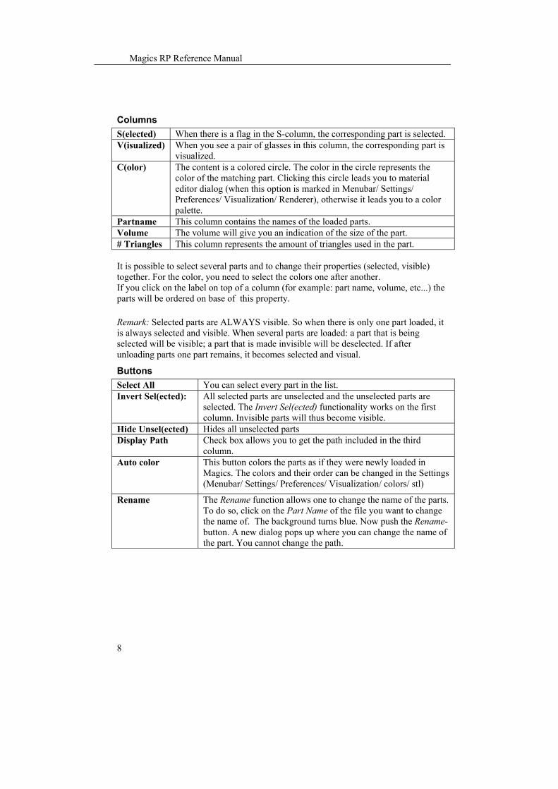
Columns S(elected) When there is a flag in the S-column, the corresponding part is selected. V(isualized) When you see a pair of glasses in this column, the corresponding part is
visualized. C(olor) The content is a colored circle. The color in the circle represents the
color of the matching part. Clicking this circle leads you to material editor dialog (when this option is marked in Menubar/ Settings/ Preferences/ Visualization/ Renderer), otherwise it leads you to a color palette.
Partname This column contains the names of the loaded parts. Volume The volume will give you an indication of the size of the part. # Triangles This column represents the amount of triangles used in the part. It is possible to select several parts and to change their properties (selected, visible) together. For the color, you need to select the colors one after another. If you click on the label on top of a column (for example: part name, volume, etc...) the parts will be ordered on base of this property. Remark: Selected parts are ALWAYS visible. So when there is only one part loaded, it is always selected and visible. When several parts are loaded: a part that is being selected will be visible; a part that is made invisible will be deselected. If after unloading parts one part remains, it becomes selected and visual.
Buttons Select All You can select every part in the list. Invert Sel(ected): All selected parts are unselected and the unselected parts are
selected. The Invert Sel(ected) functionality works on the first column. Invisible parts will thus become visible.
Hide Unsel(ected) Hides all unselected parts Display Path Check box allows you to get the path included in the third
column. Auto color This button colors the parts as if they were newly loaded in
Magics. The colors and their order can be changed in the Settings (Menubar/ Settings/ Preferences/ Visualization/ colors/ stl)
Rename The Rename function allows one to change the name of the parts. To do so, click on the Part Name of the file you want to change the name of. The background turns blue. Now push the Rename-button. A new dialog pops up where you can change the name of the part. You cannot change the path.

Chapter 2: Editing STL Files – The Edit Menu
9
8.2 Remark: Part list sheet
Part list sheet In the view menu, you can select the Part list sheet; this sheet is similar to the selection list. The difference is that this part list sheet can always be open when performing other operations.
The functionality is exactly the same as the selection list. In the first column, parts can be selected or unselected; in the second column the visibility of the parts is indicated. In the next column, the color can be chosen and in the 'S' column the smooth shading can be turned on or of. By double clicking in the part name column, a new part name can be entered. Also the buttons are the same. When you click on the arrow button in the lower left corner, the extended part selection window will be opened.

Magics RP Reference Manual
10
Extended part list
This window combines the part selection list with the information sheet ( ). The information in the information sheet is here divided over three tabs: Tab Dimensions: Displays position and dimension info. Tab Fixing: Displays number of bad edges and flipped triangles. Tab Information: Displays total number of triangle, surface and volume. Remark: When multiple parts are selected, the sum of the properties of all the selected parts will be shown An extra tab List options allows you to select which columns should be shown in the part list.
9. Pick and Place
Icon: Menu: Edit - Pick and Place Hot Key: F3
9.1 Pick and place principle This command allows the user to translate and rotate (around the axis perpendicular to the platform) selected parts on a platform by mouse movements. You can select the part

Chapter 2: Editing STL Files – The Edit Menu
11
by first clicking on the icon and then clicking on the part. The pick and place tags will appear. There are nine tags on a selected part in the pick and place mode:
One translation tag: the filled green circle located in the center of the part. Eight rotation tags: the hollow green tags located on the corners of the bounding box.
9.2 Pick and Place Translation If the cursor is positioned above the translation tag (the round in the middle of the part), the cursor will change to the translation cursor ( ). To translate the part, the left mouse button has to be pushed. If several parts are selected, they will all move in the same direction over the same distance. Remark: For speeding up the process, the option real-time interaction can be switched off.
9.3 Pick and Place Rotation If the cursor is positioned above a rotation tag (the hooks around the part), the cursor will change to the rotation cursor ( ). To rotate the part, the left mouse button has to be pushed. If several parts are selected, they will all rotate over the same angle. Remark: For speeding up the process, do not use the option real-time interaction.
9.4 Pick and place is a mode Pick and Place is a mode. Once you clicked the button you can pick and place parts until you click the button again. This feature has it's own visualization mode. All visualization changes you apply in the Pick and Place Mode will be used in this mode but not in another mode. An example: If, in the Pick and Place Mode, you select the Box view mode, Magics will display a box when you are in the Pick and Place Mode but in the other modes, you will be seeing the part in the view mode you defined there. To speed up the Pick and Place, you can switch off the real-time interaction option. Since the Pick and Place mode has its own visualization mode, setting the real-time interaction here will not change this option in the other modes.

Magics RP Reference Manual
12
This command allows easy positioning and nesting of the parts on the building platform. With the collision detection-feature (Menubar/Tools/Collision detection), the user can check if the parts are nested in a correct way.
10. Bottom Plane
Icon: Menu: Edit - Bottom Plane Description: This command allows easy orientation of the part by indicating a plane as the bottom plane. This plane will be automatically oriented parallel to the platform. The bottom plane window looks like this:
The Surface Tolerance and the Angle Deviation The user selects one triangle with the indicate plane cursor and an entire plane is marked. The decision about which triangles will be part of the same plane as the selected triangle depend on two tolerances that the user needs to be define:
The surface tolerance: it indicates the maximum deviation in mm or inches that a related triangle may have, to be part of the same plane that contains the selected triangle. The angle deviation: displays the maximum angle in degrees between the normals of a related triangle and the selected triangle, in order to be part of the same plane.

Chapter 2: Editing STL Files – The Edit Menu
13
Positioning Keep original Z-position: The part first will be rotated and next will be translated in such a way that the original minimum z position remains the same. Translate to default position: The part first will be rotated and next will be translated to the default part position. None: No translation is done.
Indicate Plane The indicate plane cursor appears: The user selects one triangle and a whole plane (according to the plane selection parameters) will be indicated by a green color:
The selected plane will become parallel to the platform (// XY-plane).
11. Translation
Icon: Menu: Edit – Translation Description: With this command, the selected parts can be moved over a distance in a certain direction.
The X, Y and Z value of the translation have to be defined. You have the option to translate a part away from its current position with a relative coordinate (Relative Translation) or you can enter an absolute position (Absolute Placement).

Magics RP Reference Manual
14
With the Translate to Default Position-button, the default part position-values are entered in the Absolute Placement Column. When Make Copy is checked, Magics will create a copy on the desired place and keep the original part on his place. Apply will perform the desired action but will not close the dialog box, so you can easily perform the translation in multiple small steps. The Advanced Translate leads you to the following dialogbox:
This makes it easy to put the coordinate system in the middle of you part or, as in the dialogbox above, in the middle of the top plane.
12. Rotation
Icon: Menu: Edit - Rotation Description: With this command, the selected parts can be rotated.
The user is asked to enter the rotation angle values around X-, Y- and Z-axis in degrees. The positive rotation sense is counter clockwise (CCK). The original z-position can be maintained. For determining the rotation center, there are two options: -The (common) center of the part(s) is taken as rotation center -The coordinates of the rotation center can be defined by the user When Make Copy is checked, Magics will apply the desired rotation on a copy and keep the original part on his place.

Chapter 2: Editing STL Files – The Edit Menu
15
Apply will perform the desired action but will not close the dialog box, so you can easily perform the translation in multiple small steps.
13. Rescale
Icon: Menu: Edit - Rescale Hot Key: CTRL+R Description: A part can be rescaled with different factors in the three main directions. The factor is a multiplying value for the dimensions in that direction. When the factor is 1, no rescaling is done, when the factor is 2, the size is doubled. In general, a factor bigger than 1 results in an enlargement of the part, a factor smaller than 1 results in a shrinkage of the part.
Rescaling is by default done around the center of each part individually. If you'd like a rescale center different than the center of the parts you can clear the Center of Individual Part(s) and enter the desired coordinates. Each part will now be rescaled around this center. If you want a part to become bigger so that the X-direction becomes 2mm larger, then enter 2 in the Delta X edit box. The corresponding factor(s) will change accordingly. Remark: When you rescale a part around a point that is not its center, the part will be repositioned.
14. Mirror Menu: Edit – Mirror Description:

Magics RP Reference Manual
16
When mirroring parts, you can choose to do this in: X-direction (around a plane parallel to the YZ-plane) Y-direction (around a plane parallel to the XZ-plane) Z-direction (around a plane parallel to the XY-plane)
The real position of the mirror plane is defined by a point of the mirror-plane. This point is by default the center of the part but you can also enter coordinates of a point. Because the mirror-planes are always parallel to two axes of the coordinate system, it is sufficient to give only one of the coordinates. Magics will only ask you for the relevant coordinate. When several parts are selected, they will be mirrored around their common center, in case you accept the default option of mirroring around the center of the Parts. If you check the 'Create Copy' checkbox, the part is copied and thus there will remain a part at the position of the original one.
15. Z-Compensation
Icon: Menu: Edit - Z-compensation Description: For models built with stereolithography and laser sintering, overcure may cause extra material to build up on down-facing surfaces. To avoid the time-consuming process of manually correcting these errors after the part is finished; the Z-compensation function can be used. To Z-compensate the selected parts, the user has to fill in a Z-compensation value in mm or inches in the following window:
The Z-compensation will classify all down-facing surfaces that need compensation and offset them with the desired value. Appropriate modifications are made to adjacent triangles to keep the part consistent and error free.
The figures above display the result of a Z-compensation:

Chapter 2: Editing STL Files – The Edit Menu
17
The first figure represents the original part The second figure represents the same part, but Z-compensated with a value of 3 mm Remove Self-Intersections: By moving the downfacing surfaces upwards, sometimes self intersections may occur. When 'remove self-intersections' is switched on, a postprocessing will remove these intersections. This might take a while if the file is big. Remark: A Z-compensation value will in reality never be bigger than 0.5 mm and this case 3 mm is used for an educational purpose. If a part has already been Z-compensated, Magics gives a warning. The properties of Main Menu/File/Properties, clicking F9 or the info button on the task bar displays the info sheet. One of the last lines tell if the part has already been Z-compensated or not.
16. Unit Conversion Menu: Edit - Unit Conversion Description: The selected parts are converted to another measurement system in such a way that the original dimensions remain but units are switched between millimeters and inches. This function is needed because the STL-format does not contain information concerning the measurement system that was used. Magics cannot see the difference between one millimeter and one inch. If the user is working with multiple parts, some in millimeter and some in inches, the unit conversion has to be used. The following rescaling factors are used:
Also when only one part is loaded but the settings do not correspond with the original design, unit conversion has to be used. Part created in Inch and settings are in millimeters Mm to inch 1*25.4 Part created in millimeters and settings are in inch Inch to mm 1/25.4
Inch to mm 1/25.4 Mm to inch 1*25.4


Chapter 3: Visualization and Manipulation of STL Files – The View Menu
1
Chapter 3: Visualization and Manipulation of STL Files – The View Menu
1. Put Toolbars and Toolsheets on the screen Via the View menu it is possible to access different toolbars and toolsheet that each group a particular kind of functions: visualization of the stl files, fixing of the files,…. You can show them on the screen by clicking on the name in the view menu. A mark will be placed in front when the toolbar or toolsheet is displayed. Most of them also correspond to an icon in the Main toolbar. Clicking on this icon will place the toolbar or toolsheet on the screen. By clicking on the icon again, the corresponding toolbar or toolsheet disappears.
1.1 Main Toolbar The main toolbar consists out of a number of icons that allow easy access to a particular dialogbox. By holding the mouse pointer on an icon, the name of the function will appear.
1.2 View Toolbar Menu: View/ View Toolbar Description: See “The View Toolbar and The View Toolsheet” section.
1.3 View Toolsheet
Icon: Menu: View/View Toolsheet Description: See Chapter 7.

Magics RP Reference Manual
2
1.4 Measure Toolsheet
Icon: Menu: View/Measure Toolsheet Description: See the “Measurement” section.
1.5 Fix Toolsheet
Icon: Menu: View/Fix Toolsheet Description: See the “Fixing” section.
1.6 Log Window From the moment Magics runs, all the performed actions are written down in a log file. This file is automatically saved as a *.log file. Its name * is composed in the following way: Magics_the year__the month_the date_the time when you do your first operation (hour, minutes, seconds).log. Here you see the log file Magics 2003_07_09_160416.log.
In the Settings (Menubar/Settings/Preferences/File I/O/Working Folder/Logging) you can define where you would like the files to be saved.
1.7 Part List sheet
Icon: Menu: View/Part List Toolsheet Description: See the “Editing/Part List sheet” section.

Chapter 3: Visualization and Manipulation of STL Files – The View Menu
3
2. Default views
Seven Default views are predefined: Front, Back, Left, Right, Top, Bottom and ISO view. Clicking on one of the possibilities (it will highlight when the cursor passes over it) accesses these views.
3. Coordinate system and Orientation indicator
The coordinate system is called WCS (World coordinate system) and it is the default coordinate system in which you work. The origin is set in (0,0,0). Sometimes, for example when the part is zoomed in, or when the part is positioned far from the origin, this coordinate system is not visible on the screen. Therefore, you can switch on the Orientation indicator. It is a coordinate system that is only there to indicate the direction of the X-axis, the Y-axis and the Z-axis of the WCS. It remains always in the bottom right of your screen, no matter how far you zoomed in on the part. This orientation indicator is drawn in fine lines to avoid confusion. It is also possible to define your own coordinate system (Menubar/Tools/User Coordinate System). The view option will always apply on the active coordinate system.
4. Visualization modes
These are the same possibilities as you find in the Mode tab of the View Toolsheet (Menubar/View/View Toolsheet).

Magics RP Reference Manual
4
5. Depth shading/Transparency
If you would like to show the parts transparent on the screen, check the Transparency item in the View-menu. If you want to see the parts to be shaded as is in nature (more distant things are darker) you can use the Depth Shading option.
6. Tag Names, Platforms, Build envelope and Part dimensions
6.1.1 Tag names Shortcut: F10 This command pasts the name of the part to the selection tag of the part.
6.1.2 Platforms visible If the user has selected a machine (File/Machine Set-up), he can choose to display its platform on the screen.
6.1.3 Build envelope If the user has selected a machine (File/Machine Set-up), he can choose to display its build envelope on the screen.

Chapter 3: Visualization and Manipulation of STL Files – The View Menu
5
6.1.4 Part dimensions Activating the part dimensions gives a view on the bounding box with the dimension of each rib indicated.
7. Rotate, Zoom, View Platform, Pan
These are the functionalities that are also accessible through the rotation tab in the View Toolbar (Menubar/View/View Toolbar).
8. Copy to clipboard and export to Jpeg
8.1.1 Copy to clipboard Shortcut: CTRL+C To make screenshots of the Main Window, you can use this feature.
8.1.2 Export to Jpeg The current view can also be exported as jpg-file. The background color can be chosen.
9. Remark There is an important difference between rotation and translation in the visualization mode and in the STL-editing mode: in the visualization mode is the part rotated in order to enable the user to inspect the part under a different angle. The position of the part relative to the coordinate system is not changed. In the STL-editing mode is the position of the part relative to the coordinate system changed.


Chapter 4: Tools – The Tools Menu
1
Chapter 4: Tools – The Tools Menu
The tools menu groups a number of handy tools to adapt the stl file. You can put a label on a part, perform a Boolean operation between parts, cut and punch the part in several ways, extrude a surface, offset the part over a small distance, and hollow a part. To allow easy fixing, you can convert shells to part, merge parts, and perform a unify operation. You can perform a triangle reduction and smoothing process. The alignment tool allows you easy positioning of the parts towards each other. The user coordinate systems can help in the aligning process, as well in positioning and fixing. It is possible to detect double surfaces, and to remove them. The filter tool allows to get rid of the small parts or small triangles. You can use the calculator in Magics. The painting tool can be helpful to divide a part. There is a collision detection tool to see if the parts well positioned on the platform. The automatic placement tool makes it possible to easily and economically position different parts on the platform. You can calculate the build time and the cost of a build of some parts.
1. Labels
Icon: Menu: Tools - Labels Description: This feature allows you to put text on a part. You have to mark triangles on the part where you wish to put the text. The text is first written on the screen and then perpendicularly projected on the selected (marked) triangles of the part. This text can be in the part or on the part. The depth, or height, of the text is also user-defined. The Font can be chosen as well as the size of the characters. The size of the characters is absolute. Thus if you have a part of a certain size you could calculate the size of your text.

Magics RP Reference Manual
2
Parameters Text: Here you type the text you like to have on the part. Font: The font can be changed in a dialog when you push the Font-button. In the example the font is Times New Roman and the size is 12. Preview: In this box the text will appear in the chosen font and size. A preview is also shown on the screen. Depth Direction: On top of part: This is the height of the text on the part. The letters that appear in the preview are projected on the part, in a direction perpendicular to the screen. Then the contours of the letters will get an offset along this projection direction, to the outside, with a distance depth. The letters will be on the part. Depth Direction: In part: This is the depth of the text in the part. The letters that appear in the preview are projected on the part, in a direction perpendicular to the screen. Then the contours of the letters will get an offset along this projection direction, to the inside, with a distance depth. The letters will be engraved in the part. Remark: The letters only appear on the surface that was marked. Mirror: The text will first be mirrored. Color Text: If checked, the text is colored in the color on the button. As separate STL: If this option is checked, the text will be a separate part.

Chapter 4: Tools – The Tools Menu
3
Move Text: Pushing this button allows you to move the text over your screen in order to position it on the marked triangles. Center: This will center the text on the screen. Apply: This will take the text on the screen, project it perpendicularly on the part and 'engrave' it in/on the part.
2. Boolean
Icon: Menu: Tools - Boolean Hot Key: CTRL+B Description: There are three kinds of Boolean operations: Unite, Intersect and Subtract.
2.1 Unite The Unite command merges the selected files into one file and trims all the surfaces to make one shell of both parts. There is no limit on the number of files that can be united. The files need to be selected.
2.2 Intersect The intersection of several parts is made with the Intersect command. There is no limit on the number of files that can intersect. The files need to be selected
2.3 Subtract To subtract one part from the other (as shown in the figure below), the user has to specify which part has to be subtracted from the other. The selected parts get automatically two different colors: one part is green, the other one is red. The user has the option: - To subtract the red part from the green one (Subtract Red from Green). - To subtract the green part from the red one (Subtract Green from Red). Subtraction is only possible between two files. The files need to be selected

Magics RP Reference Manual
4
2.4 Options
2.4.1 Unload originals The general principle of a Boolean operation is that a new part is created as the result of the interaction between the selected parts. The original parts can be unloaded after the Boolean operation. Therefore the Unload originals-checkbox should be checked. This option is default ON. Remark: The part is not automatically saved.
2.4.2 Name the resulting part You can choose to give the resulting part a new name, or to assign the name of one of the original parts. If you choose to Put the result to the new part (see the first column in the figure above), you can write its name in the second column. Otherwise you use the pop down menu in the first column to select one of the original part names.
2.4.3 Types of Boolean algorithms You can choose between two types of boolean operation. They only differ in algorithm. You can decide which one to use in the Settings window (Menubar/Settings/Preferences/General/Boolean).
3. Cut and Punch
Icon: Menu: Tools - Cut and Punch Hot Key: CTRL+X Description: With this command you can cut parts and punch holes into STL-files. First a cutting line needs to be defined. Then the cut will take place along this cutting line, perpendicular on the screen. There are four different ways to define the cutting line.
1. You can draw a polyline 2. You can draw a circle 3. You can define a cut along a line 4. You can combine different sections to define the part that has to be cut

Chapter 4: Tools – The Tools Menu
5
3.1 Polyline
Indicate Click here to start drawing the polyline by clicking on the screen. Each click will make a new point. Holding shift while drawing the polyline will snap on horizontal or vertical lines. Close: If you have drawn a closed polyline you can click on close so the program knows this is the polyline you would like to use for the cut. If the polyline you have drawn is not closed, Magics will close it automatically via the outside of the part Delete last: You can delete the last point you have indicated. Clear all: You can delete the whole polyline. Click on the button CUT if you want to cut the part. The cut will happen in a direction perpendicular to the screen, with the polyline as contour:
Numeric Instead of marking the points of the polyline with your mouse, you can also give in the coordinates of its corner points one by one. As this can only be done when the part is in top view, you only need to give the X and Y coordinates of the points. You have several options concerning the visualization of the coordinates of the points on the screen:

Magics RP Reference Manual
6
Don’t show: You choose not to visualize the coordinates. Show last: You choose to only visualize the coordinate of the last point. Show all: You choose to show the coordinates of all points. Click on the button CUT if you want to cut the part. The cut will happen in a direction perpendicular to the screen, with the polyline as contour:
Options Clearance: If you check this box, the cut-line gets an offset towards the inner side. This way you introduce a little gap between the parts that result from the cut. Round: You can choose to round the corners of the polyline with the given radius Blind cut: This will stop the incision at the plane defined by the given z-coordinate. This option only works in the top view.
3.2 Circle cut
Indicate You can indicate a point on the part. This point will be the center of the circle.

Chapter 4: Tools – The Tools Menu
7
Numeric Instead of indicating the center of the circle on the screen you can give in its coordinates. Show coordinate: You can choose to show the coordinates on the screen.
Parameters Radius: Here you determine the radius of the circle, and thus the cylinder you will cut out of the loaded part. Tolerance: The tolerance value determines the deviation between the circle drawn by the program (a polygon), and a real circle. It is the distance along the radius perpendicular on and trough the middle of one of the edges of the polygon between the cross point of the radius with the polygon and the cross point of the radius with the circle. The higher the tolerance, the bigger the deviation.
Visualization and cut Update view: If you change the parameters, you can click update view, to get an updated view of the circle. Clear: You can clear the circle The button Cut: Click on this button if you want to cut the part. The cut will happen in a direction perpendicular to the screen, with the circle as contour:
Options Notch: You can choose to add a small notch. The notch is defined by the parameters Angle, Width and Height.
Clearance: If you check this box, the cut-line gets an offset towards the inner side. This way you introduce a little gap between the parts that result from the cut. Blind cut: This will stop the incision at the plane defined by the given z-coordinate. This option only works in top view.
3.3 Free

Magics RP Reference Manual
8
Indicate You need to click on the Ind(icate) button and define a cutting line by selecting 2 points on the part. A section through this line, perpendicular on the screen, will be defined along which the part will be cut. When you have drawn the cutting line, and you would like to change the position, just click on the Ind(icate) button again and select two new points. To actually make the cut, click on the Cut button at the bottom of the window.
Options Teeth: When the part is oriented in top view (see view toolsheet, chapter 4), you can add teeth. The parameters of the teeth are height, offset; interval, base and top define the shape and position of the teeth.

Chapter 4: Tools – The Tools Menu
9
If you change one of the parameters of the teeth, you can click on the button Update View to see the new shape and position of the teeth. Clearance: If you would like to have a little gap between the two parts that result from the cutting, you can add a clearance.
3.4 Section
Cut visible triangles If you have defined a section (see Chapter 4), you can clip and flip to visualize only the part behind or before the section. With ‘the cut visible triangles functions’, you can cut out the part, which is visible. It is possible to make different combinations of sections, with each their own clip or flip. In the figure below, three sections are defined, and a clip is applied on each of them so only the part before the section is made visible. By selecting cut visible triangles, the part that was visible becomes a separate part.
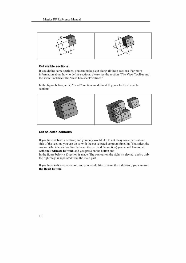
Magics RP Reference Manual
10
Cut visible sections If you define some sections, you can make a cut along all these sections. For more information about how to define sections, please see the section “The View Toolbar and the View Toolsheet/The View Toolsheet/Sections”. In the figure below, an X, Y and Z section are defined. If you select ‘cut visible sections’
Cut selected contours If you have defined a section, and you only would like to cut away some parts at one side of the section, you can do so with the cut selected contours function. You select the contour (the intersection line between the part and the section) you would like to cut with the Ind(icate button), and you press on the button cut. In the figure below a Z section is made. The contour on the right is selected, and so only the right ‘leg’ is separated from the main part. If you have indicated a section, and you would like to erase the indication, you can use the Reset button.

Chapter 4: Tools – The Tools Menu
11
4. Advanced Cut or Profile Cut
Icon: Menu: Tools - Advanced Cut Description: You can make an advanced cut along a section perpendicular to the Z-axis. Instead of just making a straight cut, there will be a step. This makes it possible to fit the parts back together once they are built. By defining 4 parameters and using the available options this cutting operation has a variety of alternatives.

Magics RP Reference Manual
12
Parameters Z upper: This parameter defines the z-coordinate of the top incision plane. Z lower: This parameter defines the z-coordinate of the bottom incision plane. dz: dz is by default chosen 1/10 of (Z upper - Z lower) when the value in the edit box is 0. When dz is chosen to high, this will affect the accuracy of you STL file between the z-coordinates Z upper and Z lower. If you need more accuracy, you can make the dz value smaller. Offset: This is the distance between the wall off the part and the step in the cutting-surface. In the example above, Z upper is chosen to be 5, and Z lower is 3. The offset is 0.5. Remark: The offset cannot be taken to big. It is also important that the part is uniform in the Z direction over the length of the step. Otherwise deformations will occur.
Options To declare the options Add inside to top, Straight Cut (which is default on) and Offset inner contours it is best to show some pictures. Add inside to top (Default OFF)
ON OFF
Z upper
Z lower

Chapter 4: Tools – The Tools Menu
13
Straight Cut (Default ON)
ON OFF
Offset inner contours (Default OFF)
ON OFF
Clearance: You can decide to make a little gap between the up facing (Z) surfaces along the cut. This way the two parts can easily slide into one another if you have to assemble them.
5. Extrude
Icon: Menu: Tools - Extrude Hot Key: CTRL+E Description: This command allows you to extrude triangles in a certain direction. Before the extrusion, you first have to mark the triangles you like to extrude. All marked triangles are moved in the same direction, over a defined distance.

Magics RP Reference Manual
14
Extrude Parameters Offset: The user must specify the extrude offset. Each triangle will undergo an offset in the defined direction over a distance defined by this value. The area of the surface formed by the triangles that are extruded will stay the same after extrusion. Calculated normal: Magics will calculate the direction himself. He will take the mean directions of the normals of the selected triangles. User defined: You can give in direction coordinates in the X, Y and Z field. Indicate triangle: You can click the indicate button and afterwards click on a triangle. The extrude offset will be the direction of the normal of the triangle. Indicate line: You can click the indicate button and afterwards click on a line. The extrude offset will be in the direction of the line. For the sense, the one of mean normal of the indicated triangles is taken. Normal: In the fields, the X, Y and Z direction of the extrude offset is shown.
Extrude operation: extrude type You can select (mark) triangles on the part that you would like to offset. The algorithm is made so that no holes are introduced. There are two possibilities to fill the gap that rises when some triangles have moved along the defined direction. Move points: The triangles adjacent to the selected triangles will be redrawn. They are stretched like shown in the figure below. The common points are moved. The area of
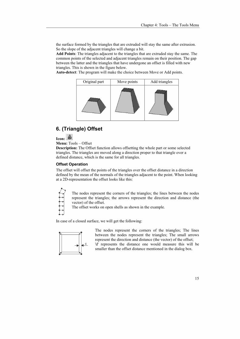
Chapter 4: Tools – The Tools Menu
15
the surface formed by the triangles that are extruded will stay the same after extrusion. So the slope of the adjacent triangles will change a bit. Add Points: The triangles adjacent to the triangles that are extruded stay the same. The common points of the selected and adjacent triangles remain on their position. The gap between the latter and the triangles that have undergone an offset is filled with new triangles. This is shown in the figure below. Auto-detect: The program will make the choice between Move or Add points.
Original part Move points Add triangles
6. (Triangle) Offset
Icon: Menu: Tools – Offset Description: The Offset function allows offsetting the whole part or some selected triangles. The triangles are moved along a direction proper to that triangle over a defined distance, which is the same for all triangles.
Offset Operation The offset will offset the points of the triangles over the offset distance in a direction defined by the mean of the normals of the triangles adjacent to the point. When looking at a 2D-representation the offset looks like this:
The nodes represent the corners of the triangles; the lines between the nodes represent the triangles; the arrows represent the direction and distance (the vector) of the offset. The offset works on open shells as shown in the example.
In case of a closed surface, we will get the following:
The nodes represent the corners of the triangles; The lines between the nodes represent the triangles; The small arrows represent the direction and distance (the vector) of the offset; 'd' represents the distance one would measure this will be smaller than the offset distance mentioned in the dialog box.

Magics RP Reference Manual
16
If the STL-file you are working on has some irregularities like in the figure below, the result may be not as expected but as shown in the right figure.
So when you have STL-noise, the offset could amplify the noise at bad portions of your part. Therefore we would recommend not using this feature for offsetting over large distances, it is better to use hollow (Menubar/Tools/Hollow) with the option keep core on checked.
Offset Parameters Offset: In this field, you enter the offset value. Each triangle will be moved along in the direction of its normal over a distance set by the offset value. Uniform: Select uniform if you wish that the offset is uniformly applied in X,Y and Z. If you switch it off, the dialog box will change so you can put different offset values in the X, Y and Z direction fields.

Chapter 4: Tools – The Tools Menu
17
Internal or external: Choose whether you want the offset to be inward or outward. Global or Local: Choose whether you want the whole part (Global) to undergo an offset or only the selection (Local). Create Thickness: If you selected global you can choose to create a thickness. In this case, the original shell will remain and a thickness is created.
Global Offset Global: You offset the whole part over a distance set in the Offset field. Create thickness: You can choose to offset the shell, and remain the original shell. This way a double surface is created, and so you create a thickness. Remark: The algorithm used here is different than the one used in the hollow function. If you like to offset the whole part over a particular distance, in order to obtain a double surface, it is advised to use the hollow function.
Local Offset You can select (mark) triangles on the part that you would like to offset. These triangles will move. The algorithm is made so that no holes are introduced. There are two possibilities to fill the gap that rises when some triangles have undergone an offset: Move points: The triangles adjacent to the selected triangles will be changed. They are stretched like shown in the figure below. The common points are moved. The area of the triangles selected remains the same after the offset. So the slope of the adjacent triangles will change a bit. Add Points: The common points of the selected and adjacent triangles remain on their position. The gap between these triangles and the triangles that have undergone an offset is filled with new triangles. This is shown in the figure below. Auto-detect: The program will make the choice between Move or Add points.
Original part Move points Add triangles
Remark: The local offset differs from the extrude operation (see point 4). In an extrude operation all triangles are moved along the same direction. In the local offset operation, the direction of offset depends on the triangle and its neighbors. Remove Self-intersections Checking this option will perform a Unify operation (see chapter after the offsetting algorithm that will remove self-intersections (see above).

Magics RP Reference Manual
18
7. Hollow
Icon: Menu: Tools – Hollow Description: The result of the hollow part operation is one stl file with two shells: the original shell and a new one that gives the part a thickness. The new shell is build from triangles whose size is determined by the parameter smallest detail.
Hollow Parameters Wall Thickness: This value display the distance over which the triangles of the original shell get an offset will be offset in order to generate a hollow part. Smallest Detail: This value displays the level of detail that will remain in the new shell. Standard, this value should be the same as the smallest detail of the part. The smaller this value, the more triangles will be included in the new shell and the more detail can thus be incorporated. Remark: If the smallest detail is chosen too high, it is possible that the internal wall intersects with the external wall.
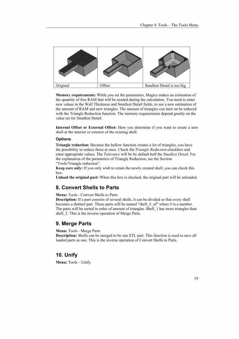
Chapter 4: Tools – The Tools Menu
19
Original Offset Smallest Detail is too big Memory requirements: While you set the parameters, Magics makes an estimation of the quantity of free RAM that will be needed during the calculation. You need to enter new values in the Wall Thickness and Smallest Detail fields, to see a new estimation of the amount of RAM and new triangles. The amount of triangles can later on be reduced with the Triangle Reduction function. The memory requirements depend greatly on the value set for Smallest Detail. Internal Offset or External Offset: Here you determine if you want to create a new shell at the interior or exterior of the existing shell.
Options Triangle reduction: Because the hollow function creates a lot of triangles, you have the possibility to reduce these at once. Check the Triangle Reduction-checkbox and enter appropriate values. The Tolerance will be by default half the Smallest Detail. For the explanation of the parameters of Triangle Reduction, see the Section “Tools/Triangle reduction”. Keep core only: If you only wish to retain the newly created shell, you can check this box. Unload the original part: When this box is checked, the original part will be unloaded.
8. Convert Shells to Parts Menu: Tools - Convert Shells to Parts Description: If a part consists of several shells, it can be divided so that every shell becomes a distinct part. These parts will be named "shell_#_of" where # is a number. The parts will be sorted in order of amount of triangles. Shell_1 has more triangles than shell_2. This is the inverse operation of Merge Parts.
9. Merge Parts Menu: Tools - Merge Parts Description: Shells can be merged to be one STL part. This function is used to save all loaded parts as one. This is the inverse operation of Convert Shells to Parts.
10. Unify Menu: Tools – Unify
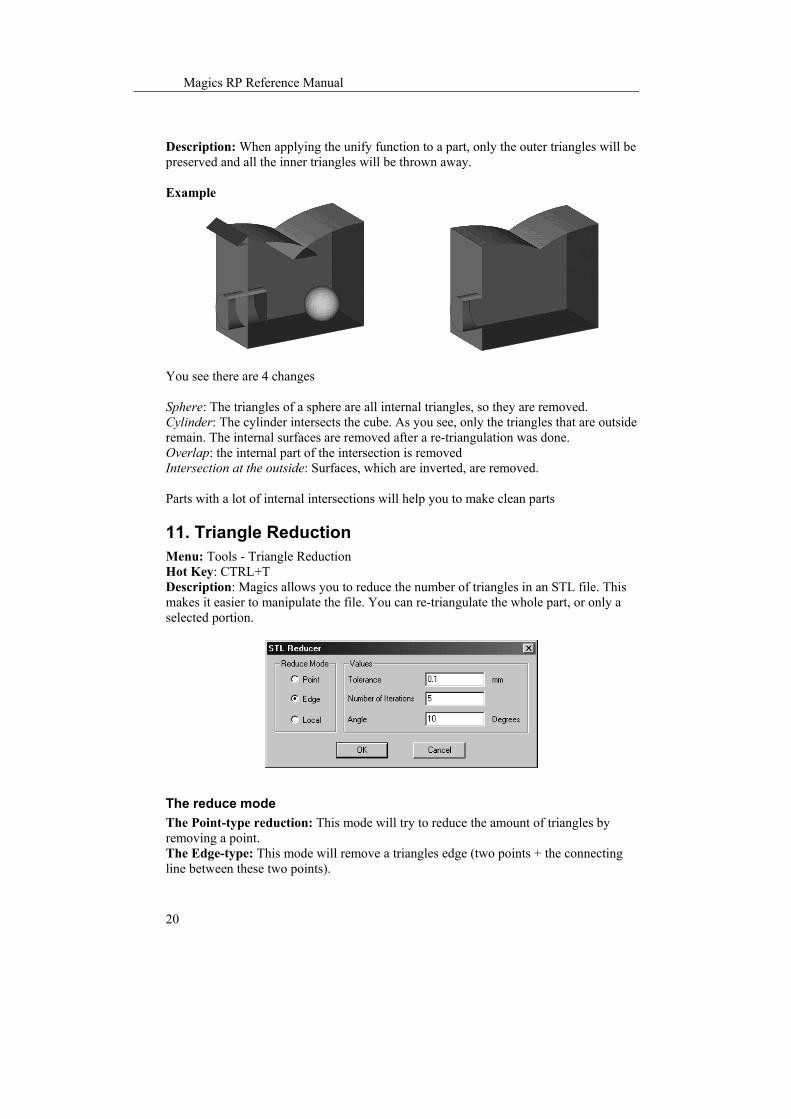
Magics RP Reference Manual
20
Description: When applying the unify function to a part, only the outer triangles will be preserved and all the inner triangles will be thrown away. Example
You see there are 4 changes Sphere: The triangles of a sphere are all internal triangles, so they are removed. Cylinder: The cylinder intersects the cube. As you see, only the triangles that are outside remain. The internal surfaces are removed after a re-triangulation was done. Overlap: the internal part of the intersection is removed Intersection at the outside: Surfaces, which are inverted, are removed. Parts with a lot of internal intersections will help you to make clean parts
11. Triangle Reduction Menu: Tools - Triangle Reduction Hot Key: CTRL+T Description: Magics allows you to reduce the number of triangles in an STL file. This makes it easier to manipulate the file. You can re-triangulate the whole part, or only a selected portion.
The reduce mode The Point-type reduction: This mode will try to reduce the amount of triangles by removing a point. The Edge-type: This mode will remove a triangles edge (two points + the connecting line between these two points).

Chapter 4: Tools – The Tools Menu
21
Local: When Local is set, only the marked triangles will be reduced. Some neighboring triangles can be changed.
Parameters Tolerance: If 2 triangles are replaced by one triangle, it may be that there is a little deviation in position. The tolerance indicates the maximum deviation allowed between the original surface and the new one. Number of iterations: It that defines how many times the program should make the calculations. Doing a triangle reduction twice with the same Number of Iterations value gives the same result as doing it once with the Number of Iterations value doubled. The angle: The Angle-value defines two limits: 1/ When two triangles have an angle value bigger than Angle, they may not be reduced, the edge between them may not be eliminated. Otherwise too much geometrical information would be lost. When the program meets such an edge, the reduction will keep the edge but reduce the number of points on the edge. 2/ When there is no critical edge, this Angle-value determines the maximum angle that can be created during the reduction. This means: where there is an edge there will remain one. Where there is no edge, no edge will be added. Remark: Because of the previous remark it is advisable not to use the reducer on very noisy objects. In this case it is better to perform a smoothing first. Remark: If the tolerance-and angle values are too big, essential part information may get lost.

Magics RP Reference Manual
22
12. Smoothing Menu: Tools – Smoothen Description:
General Options Global/Local: Global will smooth the whole part. Local will smooth only the selected triangles. Smooth Factor: We will explain this factor with the figure below. The figure shows eight triangles with one common point in the center.
The algorithm changes the position of this center point according to the positions of the eight other points. The importance of the other points can be raised or lowered by adjusting the Ratio-parameter. If this Ratio is low (0.01) the new position is mainly dependent on the old position of the point. If this ratio is 1, the dependency is spread over the points. The new position is still 50% dependent on the old position. With high values for the ratio, the new position is mainly determined by the position of the other points of the triangles. In this last case it is obvious that we talk about smoothing. This algorithm is exercised on every point of the part. Shrinkage compensation factor: The smoothing algorithm has the side effect that the part is shrinking. This factor will compensate this. This compensation step is similar to the first one except that the parameter has a negative sign - this means that point is actually moved in opposite direction (out of "smooth" position), so points "oscillate " forwards and backwards.
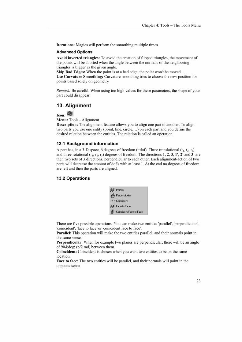
Chapter 4: Tools – The Tools Menu
23
Iterations: Magics will perform the smoothing multiple times
Advanced Options Avoid inverted triangles: To avoid the creation of flipped triangles, the movement of the points will be aborted when the angle between the normals of the neighboring triangles is bigger as the given angle. Skip Bad Edges: When the point is at a bad edge, the point won't be moved. Use Curvature Smoothing: Curvature smoothing tries to choose the new position for points based solely on geometry Remark: Be careful. When using too high values for these parameters, the shape of your part could disappear.
13. Alignment
Icon: Menu: Tools - Alignment Description: The alignment feature allows you to align one part to another. To align two parts you use one entity (point, line, circle,…) on each part and you define the desired relation between the entities. The relation is called an operation.
13.1 Background information A part has, in a 3-D space, 6 degrees of freedom (=dof). Three translational (t1, t2, t3) and three rotational (r1, r2, r3) degrees of freedom. The directions 1, 2, 3, 1', 2' and 3' are then two sets of 3 directions, perpendicular to each other. Each alignment-action of two parts will decrease the amount of dof's with at least 1. At the end no degrees of freedom are left and then the parts are aligned.
13.2 Operations
There are five possible operations. You can make two entities 'parallel', 'perpendicular', 'coincident', 'face to face' or 'coincident face to face'. Parallel: This operation will make the two entities parallel, and their normals point in the same sense. Perpendicular: When for example two planes are perpendicular, there will be an angle of 90° (p/2 rad) between them. Coincident: Coincident is chosen when you want two entities to be on the same location. Face to face: The two entities will be parallel, and their normals will point in the opposite sense

Magics RP Reference Manual
24
Coincident face to face: This is a combination of 'coincident' and 'face to face'.
13.3 Entities 'First' Entities 'Second' Entities + Defaults The defaults
There are six entities you can use to align to parts. Each entity has its specific properties. The properties are shortly mentioned in the following table. An explanation is given following the table. There are eight other entities (so called 'Defaults') you can use to align a part. These entities can be used to align a part to the coordinate system.
13.3.1 Point (Properties: Point Coordinates) A points properties are it's coordinates. There is no direction on a point. Thus when one of the entities is a point, only coincident can be chosen as operation.
13.3.2 Line (Properties: Begin- and Endpoint) A line is defined by its begin- and endpoint. It also has a direction. Thus you can make a line parallel or perpendicular to another entity with a direction.
13.3.3 Circle (Properties: Center point, Radius and the normal) A circle is defined by a center point, a radius and a normal. The normal is representing the plane containing the circle. It is shown on the screen because the user needs to know the direction of the normal in order to choose between 'Parallel' and 'Face to face'.
13.3.4 Plane (Properties: The normal of the plane and the point where you marked) A plane is defined by its normal and by the point you marked the plane with. The normal of a plane can be derived from the stl-data. It follows the normal of the triangles of the plane. (i.e. outside of the object)
13.3.5 Cylinder (Properties: Direction of the axis, radius and a point on the axis) The properties of a cylinder are the radius, the direction of the axis and a point on the axis. A cylinder is internally treated as a line (the cylinders axis). Thus a certain operation on a line or on a cylinder will result in the same change of dof's.

Chapter 4: Tools – The Tools Menu
25
13.3.6 Sphere (Properties: Center point and radius) The properties of a sphere are the center of the sphere and its radius. A sphere is treated as a point (the center of the sphere).
13.4 The user interface The alignment dialog box looks like:
On the top of this dialog box you see three buttons. The two left ones to select entities, the right one to select an operation. To the right of each button there is an arrow. Pushing these arrows pops up a list with the possibilities for this button. Pushing the arrow next to the operations button shows the possible operations for that particular combination of entities. Pushing the Properties Button reveals the entity-properties.
The description of an entity tells us if this entity was a point or a circle or a plane or ... The properties box shows the values of the properties of the chosen entity. Two selected entities and an appropriate operation are called an 'Instruction'. Each instruction decreases the amount of dof's as explained in the background information. The list of instructions can be shown pushing the Instructions button. It looks like:

Magics RP Reference Manual
26
This way you can keep track of what you have already done. OK-button: When you push this button the instructions in the instructions-list are applied and you will leave the align mode. Cancel-button: Pushing Cancel will undo all the instructions in the instructions-list and then exit the align mode. Apply-button: With this button you'll apply the alignment of the instructions-list and you'll stay in the align mode.
13.5 Way of working
Push the alignment button or choose for Main Menu/Tools/Alignment to enter the alignment mode. Only the 'Select First Entity'-button is available. Click it and mark the first entity. Then the 'Select Second Entity'-button becomes available. Once you marked the second entity, the 'Operations'-button becomes available as well. From now on you can change the first entity (type can also be changed) and the second entity (and if desired their type) or until you choose for an operation. If the listed set of instructions aligns the parts as desired, push the apply button. Now you can proceed with another alignment-session. If you want to exit push the exit button on the dialog box or the exit button on the main toolbar or close the dialog box with the 'Close'-button of the dialog box in the upper right corner of the window.
13.6 A closer look on the operations and entities Strictly there are only two operations: an orientation and a locating operation. The 'Parallel', 'Perpendicular' and 'Face to face' are pure orienting operations. The directions of the two entities are opposite at 'Face to face'. Coincident is a locating operation.

Chapter 4: Tools – The Tools Menu
27
When you choose 'Coincident' an orientation is added if the entities have a direction, as is the case for a plane. 'Coincident Face to face' is again a combination. It's the same as 'Coincident' and 'Face to face'.
13.7 Undo To Undo in the align mode, choose the Remove Last-button or use the Hotkey CTRL + z. When using the Hotkey the last instruction in the instructions-list will be removed until there are no more instructions left. From that moment on, pushing CTRL+Z will remove the 'applied alignments' of this alignment session. In the Base RP the whole Alignment-operation is one action. Thus undoing outside the alignment mode undoes the complete alignment operation. The reason is that no other action on the parts is allowed during the alignment since it keeps track of the movements to allow an undo in this mode. Be sure that all the parts needed for the Alignment-operation are selected.
14. User Coordinate System
Icon: Menu: Tools - User Coordinate System Description: You can define your own coordinate systems (UCS: User Coordinate System). Magics can work with multiple coordinate systems. These coordinate systems are not saved together with a part, because the STL-file does not support this. You can though save and load "*.ucs" files that include the description of the user-defined coordinate systems.

Magics RP Reference Manual
28
14.1 The columns of the list in the dialog box
Active (A) If you have more coordinate systems, you can make one of them active. Internally, the program works as if the active coordinate system is the only one. Creating primitive volumes, measuring, cutting, labeling ... everything is done in the active coordinate system. Therefore only one coordinate system can be active. Thus you can only see one flag in the A (Active) column of the list. In the dialogbox above UCS 1 is active. Remark: If you load a part, it will be loaded in the active coordinate system. Thus if in a previous Magics session, you saved a part at position (10,10,10) in a particular coordinate system it will be loaded at (10,10,10) in the active coordinate system. If the two coordinate systems are different, the part will have a different absolute position in the World Coordinate System, the reference system of magics.
Visualization (V) It can be useful to have a few coordinate systems shown on the screen. But not every coordinate system has to be on the screen. The second column of the list has glasses for the coordinate systems to show and grayed glasses for coordinate systems to hide.

Chapter 4: Tools – The Tools Menu
29
Remark: If you go by View Menu/Absolute Coordinate System to make your Coordinate system visible, you trigger the visibility of all the defined coordinate systems. To make 1 system visible or invisible, go to the UCS-dialog.
UCS name The name of the coordinate systems can be changed. Keep in mind that the World Coordinate System cannot be moved nor can it be deleted. Its name can be changed. Remark: The importance of short names for coordinate systems becomes clear if you take notice of the checkbox at the bottom left of the dialogbox. If this box is checked, the names of the coordinate systems will be shown on the Magics work-window. Long names will interfere with the parts.
stl When an UCS is attached to a part (see point 18.5), the name of the part is shown in this column.
14.2 Create button A first way to create a new coordinate system is to start from an existing one. Select a coordinate system in the list. You select it by clicking in the appropriate row. The background turns blue. Then push the Create-button. A new coordinate system is then created based upon the chosen one. If you do not select a coordinate system, the new coordinate system will be based upon the WCS. In a first time the new coordinate system is on the same position and has the same orientation as the one it is based on. You can then rotate and translate it.
14.3 3 points button A second way to create an UCS is by defining 3 points. First select an UCS by selecting a row. Then push on the button and go to the working window of Magics. You can select 3 points one after another on a part. The cursor pointer will change into 1, 2, and 3. The first point you indicate will be the origin of the selected UCS. The second point determines the direction of the X-axis. The Y-axis is drawn through the origin; parallel with a line that is drawn perpendicular on the X-axis through the third point indicated. The position of the third point towards the X-axis (on which side) determines the sense of the Y-axis. The Z-axis is drawn through the origin, perpendicular on the XY plane.
14.4 Delete button To delete a UCS, select it, and push the delete button. You select it by clicking in the appropriate row. The background turns blue. Remark: The WCS cannot be deleted. If you delete the active UCS, the WCS becomes active.
14.5 The move, rotate and align button After a new coordinate system is created, it can be moved and rotated.

Magics RP Reference Manual
30
Remark: The active User Coordinate System and the World Coordinate System cannot be changed.
Move button The move button leads you to the move dialog where you can enter how much you want the UCS to move in the X, Y and Z direction.
Rotate button The rotate button leads you to the rotate dialog where you can enter how much degrees you want the UCS to rotate around the X, Y and Z axis.
Align button The align button will lead you to the align dialog. The align functionality allows you to align axes or planes (XY-plane,...) of the UCS to a plane, cylinder,... of a part. For further explanation about the align function, please see point 14.
14.6 Attach stl, detach stl, align to WCS button and the hide UCS attached button
Attach stl You can attach a UCS to a part. When an UCS is attached to a part it will make the same movement as the part and the relative position of the UCS according to the part will stay fixed. To attach an UCS to a part, select the UCS (mark the row in blue) and select the part (put a flag before it). When a UCS is attached to a part, it will be shown in the column STL.
Detach stl You detach an UCS from a part by selecting the UCS in the list, and pushing the button detach stl.
Align to WCS When a UCS is attached to a part, you can make it coincide with the WCS. The attached part will make the same rotation and translation as the UCS. To do so, select an attached UCS and click the button.
The hide UCS attached button The attached UCS will not be shown in the list of UCS.
Remark When the part with an attached UCS is saved as an STL-file, a file with the extension ucs will be saved too with the same name as the part. When the part is loaded and the load UCS option is activated, the coordinate systems which are present in the * .ucs file are reloaded and attached to the part.

Chapter 4: Tools – The Tools Menu
31
14.7 Load/Save Buttons
Save button Since user coordinate systems are not saved together with the part (the STL-file format does not provide this), you can save it as a "*.ucs"-file. To save a UCS, select it first. Load button If you have saved a set of coordinate systems, they can be loaded again by means of the load-button and the usual browser.
Remark The UCS which are attached to a part will be saved and loaded automatically when the function load UCS and save UCS is activated.
14.8 Show UCS names checkbox When the box is checked, the names of the USC will appear near the origin of the UCS in the working window of Magics.
15. Double Surfaces Detector Menu: Tools/ Double surface detector. Description: This tool allows you to detect double surfaces. The definition of double surfaces is made with the help of some parameters.
Double surface Parameters Tolerance: The tolerance is the maximum distance between two triangles (surfaces) in order to be considered as double triangles (surfaces). Angle: If two triangles are inclined more than this angle, they are considered to be NO double triangles. Detect: Here you can define whether you like to detect Face to Face double surfaces (triangles with their normals in the opposite direction) or Face to Back double surfaces (triangles with their normals in the same direction).

Magics RP Reference Manual
32
16. Remove Double Triangles Menu: Tools - Remove Double Triangles Description: This tool gives you the opportunity to remove double triangles in a quick way. Two parameters define when two triangles are considered double.
Tolerance: Two triangles are considered to be double if they are closer to each other then the tolerance value. Angle: Two triangles are considered to be double if the angle between their normals is smaller than the angle value. Identical triangles: They have their normal in the same direction. When you check this box, only the double ‘identical’ triangles are removed. Opposite triangles: They have their normal in opposite directions. When you check this box, only the double ‘opposite’ triangles are removed. Remark: There is an equivalent tool available in the Load STL Option (Menubar/Settings/Preferences/File I/O/Import/stl). The difference is that the parameters of the Load-dialog are being saved.
17. Filter Sharp Triangle Menu: Tools-Filter sharp triangles. Description: When the part has long thin triangles, this filter will remove the sharp triangles.
Filter: Triangles thinner as this distance will be marked or deleted, depending on your choice.

Chapter 4: Tools – The Tools Menu
33
Angle: The thin triangle will only be selected when the angle it makes with its neighbors is bigger as the given angle. This is easy to filter only thin triangles of folds and leave thin triangles of curves untouched.
18. Small Part filter Menu: Tools - Part filter Description: When doing a shells to parts (see section “Fixing/Triangle Fixer”), the result may be a LOT of small parts, which are just noise and which are not needed anymore. You can define yourself what you consider as small. The small part filter will remove these small parts. You can choose to remove all small parts, or only the selected.
Filter Here you define the selection condition of the parts that the part filter will unload. Selected parts: The selected parts that fulfill the condition set in ‘Unload part’ are removed. All parts: All parts that fulfill the conditions set in ‘Unload part’ are removed.
Unload part Here you define the dimension condition of the parts that the part filter will unload. Surface: Parts with a surface area smaller than the defined one are removed, following the condition set in ‘Filter’. Number of triangles: Parts that contain less triangles than the defined amount are removed, following the condition set in ‘Filter’. Volume: Parts that are smaller than the defined volume are removed, following the condition set in ‘Filter’.
19. Calculator Menu: Tools – Calculator Description: This function pops up the Windows default calculator, meant for small calculations. The calculator will stay on top, so it is always visible. The copy-paste functionality can be useful here. Please note that you can switch to the scientific mode via the view menu of the calculator.

Magics RP Reference Manual
34
20. Paint Part
Icon: Menu: Tools - Paint Part Description: Parts and triangles can be painted. When you load a part it also has a color. This color is not a property of the part. It just acts like a background color to visualize the part. We call it the stl color. You can over paint this color with this paint function. When you use the color functionality, the colors assigned with the color function may be saved.
Color palette By clicking on the colored prism, a dialog with a color palette opens. You can choose a color. This color we call the paint color.
Buttons Assign: When you push the Assign-button the marked triangles are painted in the paint color. Fill: If you click on the fill button, and then on a triangle, the triangle, and all connected triangles that have the same color are painted in the paint color. When the part is painted nowhere (when it has the stl color), and you select a triangle with fill, the whole part

Chapter 4: Tools – The Tools Menu
35
will be painted with the Fill color. So, the stl color is also viewed as a color for the Fill function. Pick: If you want to change the paint color to a color some triangles of the part have, you can push the pick button and click on a triangle with the desired color. The paint color will become the ‘picked’ one Auto: With the Auto-button, each surface (amount of triangles surrounded by a wireframe) will get a separate color. Reset: The Reset-button erases the colors. The part will get the stl color. Split: The Split-button converts the shells with different colors to parts. No color: When you check the no color box, the functions will remain the same, but instead of assigning or filling with the paint color, he uses the stl color (the color the part had when you loaded it). Remark: If you save the part as 'Stl (Colored)' the colors will be saved.
21. Collision Detection
Icon: Menu: Tools - Collision Detection Description: If several parts are loaded on the vessel, Magics can detect if there is a collision (intersection of triangles of different parts). The intersecting triangles are marked in the Marked Triangles Color (default green).A message-box appears to tell you if there are or aren't colliding triangles.
22. Automatic Placement
Icon: Menu: Tools - Automatic Placement Hot Key: CTRL+A Description: This command will nest the loaded parts on the building platform. There are two options: bounding box based or geometry based nesting. While loading parts you can also be prompted to make this choice..
22.1 Bounding box based Magics will nest the parts, representing the parts by their bounding boxes. This will result in a fast nesting, however the full surface of your machine will not be used due to the rough representation of the parts. Remark: No parts are rotated with the automatic placement command.

Magics RP Reference Manual
36
22.1.1 Parameters Part Interval: the minimum distance between (the bounding boxes of) two parts. Platform Margin: the minimum distance between (the bounding box of) a part and the edge of the platform Enable 3D Nesting: If you have a machine that allows 3D-nesting you can enable this by checking the Enable 3D Nesting -checkbox. Several options are available to position the parts on the building platform:
22.1.2 Options First Possible Solution: With this option, Magics offers the first placement he
finds for which all parts are nested on the platform. Minimal Surface Area: The total surface area of all the loaded parts is minimized. Minimal X-dimension: The delta-X of the total surface area of the loaded parts is
minimized. Minimal Y-dimension: The delta-Y of the total surface area of the loaded parts is
minimized.
22.2 Geometry based A nesting based on bounding box can cause a waste of capacity in case of parts, which are having a big bounding box but a small projected area. Magics will nest the parts using the actual form of the parts and so increase the efficiency of the nesting.

Chapter 4: Tools – The Tools Menu
37
Button Description
Part distance The minimum distance between the parts. This value will also affect the speed of nesting: the smaller the value is, the longer it will take.
Platform margin The minimum distance between the platform border and the parts
All parts / Selected parts Nests all the parts or only the selected parts
Pack selected parts first
Will give priority to the selected parts. Normally the priority goes to the part with the biggest bounding box volume.
Translate only / Rotate and translate
Rotate will give Magics the liberty to rotate the parts by 90°. This will result is more efficient and faster nesting.
Press ok to proceed to the next step.
Button Description Parts packed Shows how much parts already found a place on the platform
Status Can be:
• Calculating: Magics is still calculating • Suspended: Calculation is suspended, press proceed to

Magics RP Reference Manual
38
continue • Progress halted: Probably no solution found. However
Magics will continue nesting Start Calculations To start or proceed the calculations
End To end the calculations and use the current solution Cancel To cancel the nesting and go back to the situation as it was
Show Show the current solution. Calculations will be suspended and needs to be restarted
23. Build-time Calculation
Icon: Menu: Tools - Build-time Calculation Description: There are two ways to calculate build time: Stereo-lithography based: If the user is building with a stereo-lithography machine, he can use the Stereolithography parameters of his machine. The program will take an artificial support structure into account (a grid below the part). Self-learning: In all other cases, self-learning build-time calculation is possible. The user can work with or without generated support structures. In both cases, choosing the Build-time calculation function will open the Machine Setup dialog. Here you can change the parameters of the machine (see Section “Machine Set-Up) and define which of the above build-time calculation methods you would like to use. When you click on ok, or on finish in case you ran through the wizard, Magics will ask you for the laser power value.
In the Machine setup you can also enter a value for the Laser power. In the same dialog box as where you enter this value a checkbox can be checked if you want the program to ask you for the laser power at a Build-time Calculation. The default value is the one in the Machine Setup. Changing the value here will only affect this calculation. Then the calculation can start.
23.1 Build-time calculation with SLA parameters In case of SL-based build-time calculation you will get the following result:

Chapter 4: Tools – The Tools Menu
39
Four values are displayed: the scan time of the part. The scan time of all the supports, the total recoating time and the total building time The OK button finishes the build-time mode.
23.2 With self learning build-time calculation In case of self-learning build-time calculation the following result will be displayed: Pushing the Calculate button displays the build-time:
This build-time is calculated for the current platform (all loaded parts) and is based on the teaching platforms which where specified in the machine setup. The OK button finishes the build-time mode.
24. Cost Estimator
Icon: Menu: Tools - Cost Estimator Description: The cost estimation is based upon parameters, which are Machine-dependent. Therefore, these parameters are defined in the Machine Setup. When you enter this function, the Machine set-up dialog will appear, where you can enter the machine parameters (see Chapter 3: Machine Set-Up). The cost estimator calculates the cost of making the parts. He will ask you which machine (parameters) to use.

Magics RP Reference Manual
40
When you use Copy To Clipboard you can enter these data in Excel, Word, ....

Chapter 5: Machine Setup
1
Chapter 5: Machine Setup
The Machine Setup command is meant to setup Magics for the user’s RP-machine. As a user you can choose to use one of the available machines or to specify your own machine.
1. The Machine Setup Window Menu: File - Machine Setup The Machine Setup command opens the following window:
The Machine Setup dialog box contains the following fields: The Machine platform-group with information about the current platform;
The currently selected platform has a: -Machine name: Each machine type has to have a name. If you are building
with different parameters, it is best to have a machine type for each set of parameters (e.g. layer thickness)
Remark: The machine name may consist of 76 characters and may not contain the symbol "/".
-Works with a certain material (user information) -Specific comment (user information)
The Platform Administration-group with platform administration tools The Ask for Platform on New-checkbox that activates or deactivates this option. With this option on, the command 'New Platform' automatically opens the machine setup window. This command allows to:

Magics RP Reference Manual
2
Create a new machine A new machine can be created, with the New Machine button. This machine will, by default, have the same properties and parameters as the Machine you start from. A wizard will guide you through different sheets where you can define machine and part construction parameters.
Delete a machine The selected machine can be removed from the list of machines with the Delete Machine button from the Machine Setup window. Confirmation about this action is asked.
Select a machine The machine name is displayed in a pop down window. This window contains all created machines. A machine can be selected by clicking it in the pop down window.
Change the properties of a machine The Properties button allows the user to change the properties of the selected machine in the Machine Setup window. A wizard will guide you through different sheets (the same as when you create a new machine).
Make a machine the default machine to work with When the user wishes to use the same machine every time he uses Magics, he can make that machine the default machine by selecting the machine from the list and pushing the Default-button.
1.2 Machine Setup Wizard To set a new machine or to change the properties of a machine, the Machine Setup wizard will lead you through different sheets where you can define machine properties, support parameters, slicer parameters, sla parameters, self-learning parameters and cost-estimation parameters.
1.3 Machine Properties The first step of the wizard shows you the Machine Properties dialog box.
This window contains four main elements:

Chapter 5: Machine Setup
3
The Machine Information-group (Name, Material Name, Comment) The Platform Shape-group that defines Shape of the building platform (Box or Circular) The Build-time Calculation Method-group (None, SLA Parameters, Self Learning)
• None: No build-time calculation will be performed. The machine setup is finished.
• SLA Parameters: These parameters have to be specified when the user prefers build-time calculation based on the parameters of the stereolithography machine.
• Self- Learning: Based upon some platforms that already have been build, the computer calculates the build-time for a new platform.
The Support Generation Method-group (Depending on the process used to build the
parts, you can choose for: None, Stereolithography, Volumes)
• None: when using a process that does not need any kind of a support, like SLS, choose for none.
• Stereolithography: In the Stereolithography-process, parts are built in a liquid filled vessel. To prevent the cured parts to sink in the liquid a support structure is added. These parameters have to be specified when the user prefers build-time calculation based on the parameters of the SL machine.
• Volume: Volume supports are used to strengthen sand parts, this is to avoid breakage when they are lifted out of the machine.
1.4 Platform Properties
This window contains five groups of functionality:

Magics RP Reference Manual
4
Build envelope with the dimensions of the building platform The platform can be round (Circle) or rectangular (Box). Information about the dimensions of the build envelope needs to e specified:
• In case of a box, Width, Depth and Height are prompted to fill in. • In case of a circle, the Radius and the Height of the cylinder are asked.
Platform Position The platform position values represent the position of a reference point of the platform in Magics' absolute coordinate system. This reference point is the bottom left corner for a box-shape platform and the center point for a circle-shape platform. In the following figure you can see a box-shape platform on the left and a circle-shape platform on the right. The top-pictures represent a platform at position (0,0), so in these cases the reference point of the platform is positioned in the origin of the coordinate system. The bottom-pictures show the same platforms, but now they are moved over a distance of half the platform-size in both X- and Y- direction.

Chapter 5: Machine Setup
5
Platform position Box-shape platform Circle-shape (0,0,z)
Platform position = (-50,-50,z)
The axes in bold are the representation of Magics' absolute coordinate system. The hatched axes go through the reference point of the origin.
Default Part Position These values display the coordinates (relative to the axes) of the insertion point of the part. When a part is loaded in the default part position, the minimal X, Y and Z coordinates of the part will be equal to the default part position.
Z-compensation The Z-compensation will classify all down-facing surfaces that need compensation and offset them with the desired value. Appropriate modifications are made to adjacent triangles to keep the part consistent and error free.
1.5 Support Properties Support properties can be set to the users wishes. Depending on the selection you have made in the machine properties dialog for support (none, stereolithography, volume) no sheet, a sheet with stereolithography support parameters or with volume parameters, respectively, will be shown. For the explanation of all the parameters, please see the section about “support generation”. There, all the parameters are explained in detail.
1.6 Volume Support properties Volume support properties can be set to the users wishes. Depending on the selection you have made in the machine properties dialog for support (none, stereolithography, volume) no sheet, a sheet with stereolithography support parameters or with volume support parameters respectively, will be shown For the explanation of all the parameters, please see the section about “volume support generation”. There all the parameters are explained in detail.

Magics RP Reference Manual
6
1.7 Slicer properties For the explanation of all the parameters, please see the section about “slicing stl files” There all the parameters are explained in detail.
1.8 Post-Processing parameters
Enable Post processing Post processing is an extra conversion to transform the slice format to a machine dependent slice format. So it is then a two-step process: first the file is sliced to the format determined in the Slice properties dialog (see the section “Slicing”), and then this format is converted to the format you determine here. Magics can post process to: SLI (3D systems) (License for C-Tools needed) SLI (EOS) SCDB (License for C-Tools needed)

Chapter 5: Machine Setup
7
Resolution
1/ unit size A position in the slice format is determined with 2 numbers • The unit size • A unit value The final position is determined by multiplying those 2 values. For example: when the unit size is 0.01 mm and the unit value is 1254, the position is (0.01 x 1254)= 12.54mm It is clear that to keep the maximum of detail, the unit size should be as small as possible. The only restriction is that the maximum value for the unit value is 65536 (216). So the maximum distance you can cover with a unit size of 0.01 mm is 655.36 mm. (=0.01 x 65536). So if you have a bigger machine, the solution is to make the unit size bigger. (For example the EOS 700 has a platform with a length of 700mm, so a bigger unit size must be used to cover the whole platform). So the first restriction for the unit size is: Unit size > max distance machine / 65536 In the slice format, the layer thickness is also expressed in the unit size. This results in the restriction that Layer thickness/unit size is an integer. So we should minimize the unit size keeping in mind: Unit size > max distance machine / 65536 Unit size = layer thickness * N (where N is an integer) When a user works in inch, the unit size stays in mm. So the factor 25.4 is introduced.
2/ Resolution An SLA machine works internally with a resolution (the amount of defined positions per millimeter). Some machines use unit size. Both values are linked with following relation: Resolution [1/mm] =1 / Unit size [mm] A value is used to express the position of a point. The position is retrieved with following formula: Position [mm] = value / resolution [1/mm] = value x unit size [mm] The value that is used is mostly expressed with 2 bytes, so the value has a maximum value (=216=65536). This result in the fact that the higher the resolution is, the smaller the covered area is because the maximum value is reached faster.
Hatching The hatchings are the hatches the laser makes to cure the volume inside the part. There are different parameters: X-Hatch: the distance between 2 hatches in the X-direction.

Magics RP Reference Manual
8
Y-Hatch: the distance between 2 hatches in the Y-dimension. Alternate layers: When switched off, each layer is hatched in both directions (X and Y). When switch on, a layer is only hatched in one direction (e.g. X-direction), the next layer will be hatched in the other direction (e.g. Y-direction). Hatch offset: This is the distance between the border and the hatches. This parameter is to compensate the thickness of the laser beam. Hatch Filter: Hatches shorter than this length will be ignored. Hatch style Cured resin will shrink and this shrinkage will cause internal stress, this internal stress can cause deformations. Using special techniques of hatching, the internal stress can be minimized. This will minimize the deformations. Alternated: In stead of Hatching the part always from e.g. left to right, alternated will hatch one layer from left to right en the next layer from right to left. Retracted: The hatches are in a way connecting the 2 borders of the part with each other. Because the cured resin of the hatches will shrink, they will pull at the borders and a deformation will occur. To prevent that the hatches are connecting the 2 borders, you can use the retracted-option. The hatches will only be connected to one border and leave a space at the other border so the hatch is not connecting the 2 borders anymore and so the deformation will be minimized. Staggered: When staggered is checked, the hatches will move each layer. In this way, the hatch comes between the 2 hatches of the layer below. You can compare it with building a wall with bricks, they are not placed perfectly placed on top of each other but they are moved a half brick each layer. Save First By determine what is saved first, you can determine if the laser first scans the borders or the hatching.
Retraction

Chapter 5: Machine Setup
9
Skinfills To improve the quality of the bottom and upper layer, you can apply extra hatching, called skinfills. Angle: When the angle of the surface is lower than the parameter ‘angle’, skin fills will be applied. Number: how much layers below/above the upfacing/downfacing layers should contain skinfills Hatch: the distance between the hatches of the skinfill
Merge When slicing a platform with multiple parts, each part is sliced separately. With merging these slice files, they will become 1 big SLI-file. Merge all parts: all the SLI-files of the parts will be sliced in one SLI-file Merge all Supports: all the SLI-files of the supports will be sliced in one SLI-file First: To decide if Magics should first merge or hatch. When you choose to hatch before merging, the result is that the laser will hatch the parts one by one. When you first merge before hatching, the hatches will be calculated for all parts together, so it can be that multiple parts are hatched at the same time. Original files: if Magics should keep the original files he used for merging or not.
1.9 SLA Parameters Depending on the choice you have made in the machine properties dialog for buildtime calculation method (none, sla parameters or self learning parameters), no sheet, a sheet with sla parameters or with self learning parameters , respectively, will be included in the wizard.
The following parameters have to specified:

Magics RP Reference Manual
10
Laser and Resin Parameters EC Value (mJ/sqr cm) Dp Value (mills)
These parameters concern the resin used for SL-machine. They describe the relation between the energy input by a laser and the depth of the cure in the resin. Check with your resin supplier.
Laser Power (mW) Laser Spot Diameter (mm or inches)
The Laser parameters change in time. Make sure that the Laser parameters are updated. Check your machine.
Ask for Laser power when estimating laser spot diameter
The value that will appear in a dialog box when calculating the Build-time estimation is the value you entered here. If you change the value in the Build-time calculation procedure, the value in the dialog box above will not change. If you clear the checkbox for this option, the program will always use the Laser power value of the dialog box above for his calculations.
Part Parameters Border OC and Hatch OC (mm or inches)
This is the OverCure of the composing borders and of the filling hatches of the part. Check your machine settings.
Layer Thickness (mm or inches) Recoat Time (seconds)
The recoat time is the time that the machine does not scan (between two layers). The recoat time when only supports are built can be shorter than when part and support are built together. Check your machine for accurate recoat times.
Hatch distance The distance between two hatches.
Support Parameters Border OC and Hatch OC (mm or inches)
This is the OverCure of the composing borders and of the filling hatches of the supports. Check your machine settings.
Layer Thickness (mm or inches) Recoat Time (seconds) The recoat time is the time that the
machine does not scan (between two layers).
Line Spacing
The distance between two supporting gridlines.
To actually calculate the build-time, see Menubar/ Tools/Build-time Calculation.

Chapter 5: Machine Setup
11
1.10 Self learning Build-time calculator Depending on the choice you have made in the machine properties dialog for build-time calculation method (none, sla parameters or self learning parameters), no sheet, a sheet with sla parameters or with self learning parameters, respectively, will be included in the wizard.
List of teaching platforms Self-learning build-time calculation requires a list of teaching platform files. These platforms are actually built on the machine and thus the building time (time) is known. Putting together such a list gives Magics enough information to calculate the build-time of new platforms. The estimated time is the build time you estimated before the part was build. The absolute and relative errors give the statistical errors between the estimated and actual buildtimes. If the user chooses the self-learning build time calculation method, he has to specify whether the machine has a laser with a variable energy output. If it does, check the Laser Based System-checkbox. For SLA based build-time calculation, this parameter is of no importance. In the platforms list, platforms can be added, edited or removed. When you add a platform, Magics needs to know where to find the pff file (on your PC), the actual build time and the laser power (if this is a laser based system). Show path: Click this option if you would like to see the path of the directory where the platform files are saved.

Magics RP Reference Manual
12
Parameters The two parameter lists show you the parameters that can be used for build-time calculation of a platform. The list on the left contains all the parameters that may be included in the calculation. The parameters on the right will be included in the build-time calculation. You can move the parameters from one list to the other by using the arrow buttons located between the 2 lists (first select the parameter). For the parameters on the right you can even tell Magics if this parameter depends on the laser-power by checking the flag in the Laser-column (only visible if the Laser Based System-checkbox is checked). Remark: If should have at least as much teaching platforms as there are parameters. To actually calculate the build-time, see “Menubar/Tools/Build-time Calculation”.
1.11 Cost Estimator Cost estimation is a primary need of a company. The cost estimation is done in the tools menu and is done based on parameters which are machine dependent and thus are defined in the Machine Setup. The Parameters are defined through a dialogbox that is shown here:
The Currency can be entered in an edit-box. A cost can be added, edited or removed. When adding or editing a cost, you get a dialog with three edit-fields, one for each column of the cost-list above (Cost fragment, Dependency and Cost/Unit).

Chapter 5: Machine Setup
13
You can give the cost a name (appears in the column Cost Fragment). The dependency determines from which variable the cost is dependent. It can be one of the following list. In the first column, you find the dependency, in the second column you find the unit in which this parameter is expressed. Dependency Unit Estimated Build-time Hour Fixed Cost Platform Volume Liter Support Volume Liter Surface cm² Delta X mm Delta Y Mm Delta Z Mm Number of Stl Files Part Bounding Box Volume Liter Remark: When you choose for the Estimated Build-time, the Build-time has to be calculated as well and thus all the parameters for these calculations have to be correct. Magics will even ask you for the laser-power.


Chapter 6: The View Toolbar and The View Toolsheet
1
Chapter 6: The View Toolbar and The View Toolsheet
The View Toolbar and the View Toolsheet contain all directions to the ways you can visualize the stl files. From here you can also zoom, rotate and pan.
1. The View Toolbar Menu: view/view toolbar: Description: The view toolbar contains the zoom functions, and the interactive rotate and pan functions
1.1 Zoom
Zoom To zoom in on a region, this region has to be
defined by means of a box (drag from the left upper corner to the right bottom corner). When the mouse button was pressed, but no rectangle was drawn, the Zoom In 25% function will be applied.
ALT+Z
Zoom in 25%
An automatic zoom of 25% will be applied on the window.
CTRL++
Zoom out 25%
An automatic unzoom of 25 % will be applied on the window.
CTRL+ -
Unzoom The zooming factor will be set so that all the
active parts are displayed. ALT+U
Zoom Previous
The zoom factor of the previous view will be taken back.
CTRL+ *
By clicking on the right mouse button and simultaneously on the Control button, you can zoom in if you move the mouse pointer up and you can zoom out if you move the mouse pointer down. If available, you can use the mouse wheel to zoom in and out as well.

Magics RP Reference Manual
2
1.2 Platform
This function unzooms in such a way that the whole platform is displayed on the screen. Choosing this menu item again will remove the platform, unzoom and take an ISO-view. This is a semi-mode i.e. once you choose this item in the view menu you are in the mode but if you enter another mode, exiting this other mode will not return you to the platform mode.
Shortcut F11
1.3 Pan
If you click on this icon, then you can move the part in the window plane by dragging the part with the cursor (keep left mouse button down). This does not change the position of the part in the coordinate system. This function can also be accessed via Main Menu/View/Pan.
Shortcut ALT+M By pointing the mouse on the part and clicking shift and the right mouse button simultaneously, you can also move the part.
1.4 Rotate (interactive)
The user can rotate the part around the three axes. The interactive rotation has two different cursor-images, depending on the cursor (mouse pointer) position on the screen. When the cursor is near the middle of the window it will have a quadruple arrow shape, the movement of the cursor is translated in a rotation around the axes in the screen (horizontal and vertical). When the cursor is near the borders of the window it will have circular arrow shape, the part can be rotated around the axis perpendicular to the screen. Rotation takes place around the center of the image you are looking at. This way there is more control when you are working with large zoom factors. This movement does not change the position of the part in the coordinate system. This function can also be accessed via Main Menu/View/Rotate.
Shortcut ALT+R F4 By pointing the mouse on the part and clicking the right mouse button, you can rotate the part.
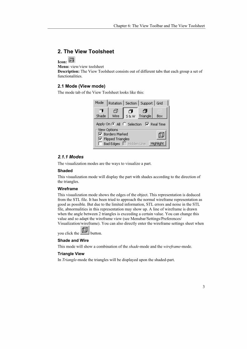
Chapter 6: The View Toolbar and The View Toolsheet
3
2. The View Toolsheet
Icon: Menu: view/view toolsheet Description: The View Toolsheet consists out of different tabs that each group a set of functionalities.
2.1 Mode (View mode) The mode tab of the View Toolsheet looks like this:
2.1.1 Modes The visualization modes are the ways to visualize a part.
Shaded This visualization mode will display the part with shades according to the direction of the triangles.
Wireframe This visualization mode shows the edges of the object. This representation is deduced from the STL file. It has been tried to approach the normal wireframe representation as good as possible. But due to the limited information, STL errors and noise in the STL file, abnormalities in this representation may show up. A line of wireframe is drawn when the angle between 2 triangles is exceeding a certain value. You can change this value and so adapt the wireframe view (see Menubar/Settings/Preferences/ Visualization/wireframe). You can also directly enter the wireframe settings sheet when
you click the button.
Shade and Wire This mode will show a combination of the shade-mode and the wireframe-mode.
Triangle View In Triangle-mode the triangles will be displayed upon the shaded-part.

Magics RP Reference Manual
4
Box This mode will only show the bounding box of the part. This mode is quick in visualization. When the loaded parts are heavy, the program will automatically change to this mode for manipulations. There is also the possibility to visualize the part with depth shading and transparent (Menubar/View/Depth Shading or Transparency)
2.1.2 Options
Apply on All/Apply on selection This option is meant to give the user the opportunity to change the visualization of different parts in Magics separately. If the option is set to Apply on all, every change of the visualization mode (Shade, Wire, Shade & Wire, Box) will be applied to each part. When the option is set to Apply on Selection, every change of the visualization mode is applied only to the selected parts.
Real-time Interaction Checking this checkbox enables the user to see the objects in Shading, Shading and Wireframe, or Triangle visualization modes while rotating and moving the view. If this option is switched to OFF, the bounding box will temporarily take the place of the part. This is especially handy when the loaded files are very big and rotating or moving is going slow.
2.1.3 Visualization Options A part of the toolsheet is dedicated to some View Options:
Show Flipped Triangles Defects in the STL file can be detected graphically. If the Show Flipped Triangles-checkbox is checked, all triangles with a normal pointing into the screen are displayed in the Flipped Triangles color which is default red. Remaining red triangles in the shading thus indicate defects in the STL file (triangle with wrong-oriented normal, missing or overlapping triangles...)
Show Bad Edges Defects in the STL file can be detected graphically. By checking the Show Bad Edges-checkbox, all edges that are not shared by exactly 2 triangles will be displayed in yellow on the screen. This option is available for all visualization modes.
Bad Edges with Hidden Line The user can hide the indication of the bad edges that are situated behind or inside the part. To do so, check the Hidden Line-checkbox.
Highlight Bad edges are sometimes difficult to spot. When pressing the button highlight, the bad edges will be drawn with thick lines so you can see them easily.

Chapter 6: The View Toolbar and The View Toolsheet
5
Borders marked This function will draw a line around the marked triangles. This function is very useful to see if you did not skip a small triangle.
2.2 Rotation (Relative rotation) The rotation tab of the View Toolsheet looks like this:
The STL part can be rotated along the three axes, relative to the current position. Click on the slider, and drag it to the end position (keep the left mouse button pressed). During the dragging, the part will be visualized by a box (the Real-time option not checked –see section “The View Toolbar and the View Toolsheet/The View Toolsheet/Mode”) or in selected mode (the Real-time option checked –see section “The View Toolbar and the View Toolsheet/The View Toolsheet/Mode”) and will rotate. After the rotation, the slider will jump back to the center position. It is also possible to rotate in steps. Click on the slider bar and you rotate your parts in steps of a magnitude as entered in the Delta box. The rotation is in this case around the screen-axes: X-slider: Rotation around the horizontal screen axis Y-slider: Rotation around the vertical screen axis Z-slider: Rotation around the axis perpendicular to the screen.

Magics RP Reference Manual
6
2.3 Sections Sections can be used to measure accurately, to check for errors and (in combination with some of the options) to look inside the model and to get a better comprehension of the geometry. The section tab of the View Toolsheet looks like this:
The Section Tab
The menu that appears when you click the define button
2.3.1 Different ways a section can be chosen
The X, Y and Z sections These are perpendicular to the X, Y and Z-axis respectively. The default position of such a section is taken through the origin.
User defined sections Section defined on 3 points: The user can define a section by indicating 3 points. Section defined by a normal: The user can select a line. This line will then become the normal of that section. Section defined by a triangle: The user can select a triangle. A section will be defined that is in the same plane as the triangle. Section parallel to the screen: The user can choose for a section that is parallel to the screen. With the define button, you can choose the section you like. The selected row in the window will show the section information.
2.3.2 The section window The section window displays several rows and columns. The rows display the different sections. A section is selected when the row is gray-colored. The columns display V (Visible), Type, Clip, C (Color), Pos (Position) and step.

Chapter 6: The View Toolbar and The View Toolsheet
7
Type: Here is shown the type of section is displayed (X, Y, Z or user). Visible: By flagging this column you can make the section visible. Clip: Here you can select if you want to hide a side of the part. In this way, it is possible to look inside the solid part. The inside is colored in the Flipped Triangles color (default red). Color: You can assign a different color to each section. Position: This number indicates the position of the section along the axis perpendicular to it. The units used are the units you work in (inch or mm). You can also fill in a number and the section will move to this position. Step: Under the window you find a slider bar. If you click to the left or to the right from the slider on the slider bar, the section will move a distance indicated by the Step value. The same happens if you use the arrow buttons on your keyboard.
2.3.3 Slide bar You can take parallel sections by sliding the slider in the slide bar. The section will be calculated and displayed in real-time while you change the position. The position of the section is noted in the Position column. If you click to the left or to the right from the slider on the slider bar, the section will move a distance indicated in the Step column. The same happens if you use the arrow buttons on your keyboard.
2.3.4 The buttons (align, indicate, export, define)
Align When you push the align button, the part (and the section) will be rotated until the section is aligned with the screen.
Indicate button With the Indicate-button, the position of the section can be pointed on the part. The position of the section will be displayed in the Position column.
Export The export option in the section is meant to export the section as an IGES-polyline or as dxf file.
Define If you click the Define button, a menu with the different kind of sections pops up (see the left figure in the table). You can click on one of the section types (3 points, normal, triangle, screen, X, Y and Z) and define a section.
2.3.5 Section Only With this option selected, the STL object will not be displayed anymore, only the section remains on the screen, together with all the measurements.
2.4 Support The support tab of the View Toolsheet contains the visualization options of the support structures (see Chapter 12):

Magics RP Reference Manual
8
2.4.1 Main buttons None: No supports are shown Shade: Supports are shown in shade mode (default) Triangle: Supports are shown with their STL triangle layout.
2.4.2 Options View Surfaces (Works only in the support generation mode): Outlines the active surface in red. Hidden Line (Works only in support generation mode): When this option is checked, the red outline is hidden when the surface is not visible. View Support Edge: Gives the Support Edge a bright yellow color. Transparent: Checking this item will make the support transparent. Show perfo(rations): You can visualize the perforations in the supports. Section: You can also make a section of the support structure (in X and Y) when the clip box of that section in the Section Tab is checked.
2.5 Grid It is possible to display a grid on the screen.
2.5.1 Layout Visible: You can hide the grid by keeping the Visible option blank. Axis Visible: The axes form the intersection of the grid with the XZ an YZ planes through the origin. Default they are part of the main and second grid and colored in

Chapter 6: The View Toolbar and The View Toolsheet
9
white. When you like to accentuate these axes, you can check this box. The axis will turn red.
2.5.2 Main and second grid Main grid: You can define the grid size here. The main grid is colored brown. Second grid: If you would like a second grid imposed on the main grid, which is less detailed, you can here fill in a number n. The lines of the second grid will lie n times further apart as the lines from the main grid. The second grid is colored white.
2.5.3 Size Total grid size: Here you can set the total grid size. Auto Extend: When this box is checked, only one mesh of the second grid is shown.


Chapter 7: Measuring
1
Chapter 7: Measuring
The Measure Toolsheet can be displayed via the View Menu, or with the Measure
Toolsheet icon in the Main Toolbar. The measurement toolsheet has different tabs: You can measure distances, radii (or diameters) and angles. You can also display some coordinate information of different features in the part: a point, a line, a triangle, a cylinder, a circle and a sphere.
1. Selecting Features Magics recognizes different features: a point, a line, a plane, a circle, a cylinder and a sphere. You select a feature by moving the pointer of the mouse. You will snap (the feature will be marked when you move over it) to all features of the type you would like to select (for example points-see figure- are marked with a round) and which are not disabled by the snapping settings. You may for example determine that you only want to snap to points that are in a section, or on a wireframe…(see Menubar/Settings/Preferences/ General/Snapping).
By clicking the left mouse button, you will select the marked feature. When all features of the measurement are selected, they will be marked if the draw feature in the measurement part of the settings is checked on (see Menubar/Settings/Preferences/ General/Snapping). For example a point is indicated with a cross (see figure), a line with a line (see figure), and a sphere with 3 circumpolar circles. When the draw feature in the measurement part of the settings window is not on, the feature may be selected but is not indicated in a special way.

Magics RP Reference Manual
2
2. Measuring Distances You can measure the distance between several features.
FROM
First feature to select
TO
Second feature to select
To do so choose the first feature in the menu (by clicking on it), snap the feature on the part and click on it to select it, then choose the second feature in the second menu (by clicking on it) and snap to the feature on the part and then click on it to select it. You can then choose where you want to display the measurement on the screen. When you click a last time, the measurement value will be fixed. Feature The length Point The length from the second feature to the point. Line The length of the perpendicular through the second feature on the line. Circle The length of the perpendicular through the second feature on the line. Plane The length of the perpendicular through the second feature on the plane.
If you select a plane, Magics will snap to a triangle in that plane. Cylinder The length of the perpendicular through the second feature on the
middle line of the cylinder.

Chapter 7: Measuring
3
Sphere The length from the second feature to the center of the sphere.
X, Y and Z You can choose to measure in 1, 2 or 3 dimensions. Remark: The measurement is dynamic: When you have selected the first feature, Magics will look for the second feature as you move your mouse over the part. The measurement value will change as you snap to features at different positions..
3. Measuring radii or diameters
You can choose the type of radius measurement you would like to make by selecting it in the drop down menu by clicking on the option. 3 points Select three points. The radius (or diameters) of the circle defined by
these three points will be displayed. Be aware that it is possible to indicate three random points. This can result in a non-existing arc! It is advised to use the radius of an arc measure function when possible. Use this function only when the arc is not recognized by Magics as a feature.
Circle Select an arc. The radius (or diameter) of the arc will be displayed. Sphere Select a sphere. The radius (or diameter) of the sphere will be
displayed. When you have selected the features you will have to click the left mouse button one more time to give the measurement value a fixed position on the screen. It is possible to change this position afterwards (see next point). If you rather would like the diameter displayed, you can check this option.

Magics RP Reference Manual
4
4. Measuring Angles
FROM
First feature to select
TO
Second feature to select
You can choose the type of radius measurement you would like to make by selecting it in the drop down menu by clicking on the option. 3 points Select three points. Two imaginary lines will be drawn between
those points: between points 1 and 2, and between points 2 and 3. The resulting angle is the angle between those two lines defined by the three points. (You only have to use the ‘from side’). Remark: It is advised to use the angle between two lines measure function when possible. Use this function only when the lines can't be recognized by Magics as features
Line Select the two intersecting lines. Both lines will be highlighted, and the intersection point will be drawn. The resulting angle is the angle between those two lines.
Plane Select two planes. When you have selected the features you will have to click the left mouse button one more time to give the measurement value a fixed position on the screen. It is possible to change this position afterwards (see next point).
5. Retrieving information

Chapter 7: Measuring
5
When you snap to a feature, or you select it, some coordinate information of the features is given. This information would allow you to draw exactly the same feature on the same point in space. Point The X, Y and Z coordinate of the point will be displayed. Line The X, Y and Z coordinate of the beginning and end points will be
displayed, together with the length of the line. Arc The X, Y and Z coordinate of the center of the circle imposed on
the arc is given, together with its radius. Triangle The X, Y, Z coordinates of the corner points and the direction
coefficient of the normal will be displayed. Cylinder The X, Y and Z coordinate of the middle points of the bounding
discs is given, together with the radius. Sphere The X, Y and Z coordinate of the middle point of the sphere is
given, together with its radius.
6. Selecting a measurement
To select a measurement, you click on the icon ‘select parts’ in the menubar or in the toolsheet, (the mouse pointer gets a green round to show you are in the measuremet selection mode) and you click on the measurement value. When the measurement is selected some grips will appear. In the figure, the measurement with value 11.76 is selected. There is a grip in the middle of the measurement line and on one of the intersections of the extension line with the measurement line.
Extension line
Measurement line
A Grip

Magics RP Reference Manual
6
7. Reselecting the features to adapt the measurement It is possible to adapt a measurement by dragging one of the feature indicators to a same feature positioned elsewhere on the part. This way you get a new measurement. To do so you first have to select a measurement.
8. Changing the measurement visualization
8.1 Lay-out In the settings window (Menubar/Settings/Preferences/Visualization/Measurements). you can indicate how you would like to display the measurement (with or without arrows and extension lines, the size of the grips….).
8.2 Position If you are not satisfied with the position the measurement value has on the screen, you can change this position. You have to first select a measurement with the mouse. If you select the grips at the cross points of the extension lines, you can turn the measurement indication line around the axis that connect the features selected. When you select the grip in the middle of the measurement line, you can make the extension lines longer or shorter.
9. Deleting measurements Selected dimensions can be deleted with the Delete button on the keyboard. To delete one or more dimensions (but not all), one has to follow these two steps:
1. Select the dimensions you want to delete (keep the shift button down to select several dimensions).
2. Hit the Delete button on the keyboard. All measurements can be deleted at once by clicking the Clear all dimensions button in the measurement toolsheet.

Chapter 8: Fixing stl Files
1
Chapter 8: Fixing STL-files
To fix a corrupted STL file, the trial and error method is used in many cases. Sometimes, the fixing can damage the part, for example when stitching is done with a large gap fill tolerance. That is why it is advised to save the result of a set of fixing operations. This way, the user does not need to start all over when severe damage was done to the part he was fixing. In case you only want to go back on or two steps of fixing, the undo-function can be used.
The fixing toolsheet is activated with the command Fix Toolsheet from the View Menu. Magics allows the user to produce error free STL files: gaps, inverted normals and double surfaces can be removed. In order to make the fixing easier, triangles can be marked or made invisible. To fix STL files, Magics works with five modules: The automatic fixer, The normal-fixer, The triangle-fixer, The Holes filler, The Point fixer.
1. Automatic Fixer Menu: View: Fix Toolsheet: 'Automatic' Tab Description:
There are three kinds of errors that have to be fixed: Flipped normals have to be inverted Gaps between triangles have to be fixed Holes have to be filled

Magics RP Reference Manual
2
Automatic fixing will trace all errors in the selected parts and next fix where possible. You can do the automatic fixing in two ways: 1/ You fix listed errors in one step (Do All). 2/ You can fix a particular kind of error (Normal inversion, stitching, Hole fill))
1.1 Do All With this button you can perform several fixing operations in one step. You have the following options: Normal Fixing, Stitch, Fill Holes
1.2 Normal Fixing With this option, the program will automatically try to point all the normals to the outside of the part.
1.3 Stitching The Gap Fill Tolerance displays the maximum distance that a point will be moved in order to fill a gap. Triangles are stretched in such a way that the gap is closed.
If a side of a triangle is shared by more then one neighbor, stitching also corrects the STL-error by dividing the original triangle into different triangles. The original triangle (1) is divided into two triangles (1a) and (1b) that correspond with the triangles (2) and (3).
The higher this tolerance, the more bad edges will be fixed. The accuracy of the part however will get lost when using very high tolerances because then the part is torn apart or/and deformed:

Chapter 8: Fixing stl Files
3
When the gaps are too large, it's better to add triangles to fill the gap(s). The following example shows very clearly the effect of large stitching tolerances.
Original cube One triangle deleted Stitching with high
tolerance With this value, the gap fill tolerance is fragmented by the formula 't/2(imax-i)' with 't' the gap fill tolerance and 'i' the number of iteration and 'imax the total number of iterations. For example: with the gap fill tolerance set to '0.1' and the number of iterations set to'5', gaps are closed in the following order: • 0.00625 (first iteration) • 0.0125 • 0.025 • 0.05 • 0.1 (last iteration) The Stitching-algorithm runs through more than once. That means, that Magics stitches in the first step only very small gaps. With each step the stitch tolerance is raised and thus the program stitches bigger gaps. In the last step it uses the choosen value for stitching. In this way, the stitching is very detailed.
1.4 Fill Holes Magics will try to fill all detected holes in the part. When Freeform is selected, Magics will fill the holes with the freeform surfaces using the given gridsize.
1.5 Fix Error Category With the Stitch button you stitch all the bad edges of the selected parts that have a maximum gap fill distance that is smaller than the gap fill tolerance. With the Fix All Holes command all holes in the part are tried to be fixed.

Magics RP Reference Manual
4
2. Fix Normals Menu: View: Fix Toolsheet: 'Fix Normals' Tab Description:
Button Description Triangle The normal of the selected triangle is inverted. Double
clicking restores the original status of the normal. (This is a mode.)
Shell All the normals of the triangles of the shell related to the indicated triangle are inverted. The normal of the indicated triangle will be inverted, and all triangles of the same shell will have an according normal. (This is a mode.)
Invert Marked The normals of a marked set are inverted. Invert Part All triangles of the selected part are flipped. Recalculate Normals For some triangles, normals can be defined in a wrong way.
This command recalculates all normals of the selected parts in order to obtain a correct fixing.
Automatic See automatic fixer.
3. Triangle Fixer Menu: View: Fix Toolsheet: ‘Triangles’ Tab Description:
Delete The indicated triangle will be deleted. 'Delete' is a mode.

Chapter 8: Fixing stl Files
5
Create A new triangle is created. The triangle is snapped between existing triangles. The user is prompted to indicate three points. 'Create' is a mode.
Stitch All The Stitch All function will close gaps between all bad edges, if the gap is smaller than the tolerance
Stitch Marked Magics tries to close the gaps between the Marked triangles in one iteration with a selected tolerance. The value for stitch tolerance, here 0.01, depends on the part and the contours
Shells to parts Makes a part from every shell in the active part. See also Shells to parts in the tools menu.
Separate Marked The marked triangles are separated from the original part and stored in a separate part
Delete Marked Marked triangles are deleted
Cut Marked With this function one can trim triangles of one part that are intersected by other triangles. In the following example the cylinder and the box are one part. The triangles of the cylinder wall are crossing the triangles of the upper plane of the box. The triangles from the cylinder stretch from the bottom to the top plane, the plane of the box only consists out of 2 triangles. We have drawn the contour of a triangle in each surface in a bold line to show the difference after trimming. We advise you to go to triangle mode.
To trim, you need to select one of the surfaces in which lay the triangles that need to be trimmed. In the example we select the upper plane of the box.
When you choose for Cut Triangles then the result is like:
The upper plane of the box is selected.

Magics RP Reference Manual
6
The surfaces are remeshed in such a way that the triangles end on the intersecting line between the two surfaces. It is now possible for example to mark the triangles of the cylinder wall above the intersection with the upper plane of the box, and delete them.
Merge Parts All selected parts are merged. See also Merge parts in the tools menu.
Undelete Sets of deleted triangles can be recovered
Double Surfaces Detects double surfaces as described in the tools menu
Unify This function will remove all the internal triangles and keep only the outer shell. Extra information in the tools menu
Update View This function recalculates the wireframe in order to give an updated view of the remaining bad edges
4. Fill holes Menu: View: Fix Toolsheet: ’Holes’ Tab Description:
Button Description
Fill Hole This command will fill a hole. If you click, Magics will find the closest bad contour and fill this bad contour with triangles. 'Fill Hole' is a mode.
Mark Edges Allows you to mark bad edges for using the multi-contour hole fill. 'Mark Edges' is a Mode

Chapter 8: Fixing stl Files
7
Multi This command will fill a hole, which consists of multiple bad contours. You first need to mark the related bad edges with 'Mark Edges'
Normal/Rules/ Freeform Magics offers multiple ways for filling a hole
Mark new triangles Magics will mark the new created triangles when this option is active.
4.1 Fill hole modes Normal Magics will take the fastest and easiest triangulation. This mode gives the fastest result for normal holes.
Ruled
When the geometry of the hole is getting complex, a ruled fill hole can make sure that the triangulation is directed in the right way. This type of hole-filling is meant to fill in a direction. The X-, Y- or Z-directions are obvious. Indicate is a way to show Magics which direction to fill in by selecting a line. You can enter a direction in coordinates as well.

Magics RP Reference Manual
8
Freeform Magics will fill the hole using a freeform surface. This Freeform will consist of a grid of small triangles. The size of the grid can be given as parameter. The smaller the gridsize is, the more triangles will be created. When tangent is checked, Magics will try to make a surface, which fits fluently. The result is depending a lot of the quality of the file and the proportion of the grid size and the size triangles.
5. Point fixer Menu: View: Fix Toolsheet: ‘Points’ Tab Description:
Magics also offers the possibility to fix on point level. There are 2 kinds of points:
User points
These points are created by the user using the Create button. The coordinates you need to create those points can be retrieved from the info-box in the measuring toolsheet (these values are copy-pastable via the right mouse button)
Free points
These points are created when all the triangles, which are using this point, are deleted. When all these connected triangles are deleted, Magics will keep the points so you can use them later again. Description
Add This mode will enable you add Free points to the list of User points.
Delete This mode will enable you to delete points. You can only delete points, which are not connected to a triangle.
X, Y, Z Use these fields to enter the coordinates of the new point to create. Create A new point will be created using the given coordinates.

Chapter 8: Fixing stl Files
9
Delete Free This button will delete all the Free points
Also User When this option is check, also the userpoints will be deleted when pressing the delete Free button
Show points Check this to show points the current present points. You can only see and use the points in Magics when they are visible


Chapter 9: Marking
1
Chapter 9: Marking
In order to fix a corrupted STL file, the user can mark triangles of a selected part. Next fixing operations can be executed only on the marked triangles. The part must first be selected before triangles can be marked! To indicate that a triangle is marked, the triangle turns (default) green.
1. Marking Triangles
Icon: Hot Key: F5 Description: Triangles can be marked one by one. Marked triangles can be unmarked by indicating them with the mark triangle cursor again. To speed up the marking process, the following objects can be marked:
2. Marking with a window
Icon: Description: With this tool, you can mark all triangles within a rectangular area. The conditions for a triangle to be in the selection are: - The triangles should be visualized with at least one pixel on the screen - At least a portion of the triangle should be situated in the rectangular area To unselect a portion use the Shift key in combination with a rectangular area.
3. Marking Shells
Icon: Hot Key: F7 Description: A shell is defined as a limited collection of triangles correctly connected to each other. A triangle is part of a shell when the direction of rotation of the vectors of two adjacent triangles is opposite:

Magics RP Reference Manual
2
To unmark a marked shell, the mark shell cursor is used again.
4. Marking a surface
Icon: Description: You have the possibility to mark a surface at once. A surface is surrounded by a wireframe. (see Menubar/Settings/Preferences/Visualization/ Wireframe)
5. Marking an edge
Icon: Description: With this function, you select triangles connected to an edge. The edge as well as the marked triangles obtain the marked triangles color, which you can set in the settings window (see Menubar/Settings/Preferences/ Visualization / Colors/stl)
6. Marking a plane
Icon: Hot Key: F6 Description: By clicking one triangle, a whole plane can be selected or unselected. The plane is not necessary perfectly flat. It can also have a complex shape depending on the plane selection parameters. These you can set in the settings window (see Menubar/Settings/Preferences/General/Plane Selection)
7. Color
Icon: Description: When you use this button, you can select any area of triangles with the same color.
8. Connect
Icon: Description: When marking triangles, it can be difficult to select the very thin triangles. With this function, Magics will mark thin triangles between 2 marked triangles. When you click on this icon, you need to enter two parameters. Max(imum) edge length: when the distance between 2 marked triangles is smaller than the given value, the triangles between the 2 marked triangles will be marked. Angle: If the two selected triangles are to inclined towards each other- if their normals have an angle bigger then the value – the connect function will not work.

Chapter 9: Marking
3
9. Toggle marked
Icon: Description: With the toggle button the selection of marked triangles is inverted: all gray triangles turn green (or the defined marked triangles color) and vice versa.
10. Unmark
Icon: Hot Key: F8 Description: All triangles will be unmarked.
11. Hide Triangles
Icon: Description: In order to ease up the fixing, Magics allows the user to make the marked triangles invisible. This way, double surfaces are easily detected. Invisible triangles are not deleted and cannot be marked or deleted.
12. Toggle Visible - Invisible
Icon: Description: All visible triangles will be hidden and vice versa.
13. All Visible Icon: Men Description: All triangles will be visible. The original marking disappears.


Chapter 10: Settings
1
Chapter 10: Settings
In the settings menu you can define a number of parameters and set a number of conditions that influence the working of Magics functions. In this menu you also find the registration window and the dealer ID.
1. Dealer ID This ID mentions the dealer you bought this software from. If you work on windows NT, you need to be administrator to change this.
2. Licenses This Menu-item leads to the registration dialog box where you can see which modules you have licensed and when these licenses expire. In this window we see 2 groups: the Module Registration State-group and the Registering New Modules-group.
In the program-box the version number and the used platform are shown.
Module Registration State The registration state shows, which Modules are active. For each listed Module you can also see until when this Module will remain active.
Register new modules Step 1: Obtaining a Registration Password To obtain these passwords, please contact us with the following information: - Your name, - Name of the company or institution,

Magics RP Reference Manual
2
- Program name and version number, - USER CODE - System ID of the computer on which the software is installed, - Your coordinates (address, phone/fax numbers, e-mail) if we don't have it already. To help you gather this information, push the Request Passwords-button the registration dialog and enter the information in the sheet. Our Fax/Phone numbers and e-mail addresses can be found in the contact information. To evaluate the software you receive Evaluation Passwords, which are valid one month. After this period the software does not work anymore. Entering new passwords can reactivate it. After purchasing the software you receive License Passwords. These will last for six months and will be renewed after this period. In this way, you get the opportunity to switch to another computer at the end of the password period. Step 2: Registration Once the passwords are obtained, they can be entered in the passwords area. Click the OK button and the software will be activated.
3. Preferences Menubar: Settings/ Preferences
Icon:
3.1 User Profiles A user profile is a file that contains all the settings of the settings menu. Each Magics user can use different settings. To avoid that you each time have to reset your settings when another user has changed them, you can save them as a user profile. These files have the extension .xml. They are default saved in the folder C:/magics profiles. You can change the folder by clicking on the folder icon on the right, browsing and selecting a location.
Import: You can import a user profile from a certain location and place it in the folder chosen. Export: You can export a user profile to a certain location. Save Profile As: You can save a profile: the current settings will be written in a .xml file that will be saved in the folder chosen. Delete: You can delete a profile.

Chapter 10: Settings
3
3.2 General
3.2.1 Unit Size
Units
You can choose between mm and inches. You have to select the units before you load the stl-file. If the STL file was originally in millimeters, you have to choose mm. If the file was in inches, you have to choose Inch. If several parts are loaded, some in millimeters and some in inches, the unit conversion has to be used otherwise parts are out of proportion. The program always remembers the last used unit and takes this as default the next time you start up the program.
Automatic Unit Conversion
The automatic unit conversion is used to avoid mistakes due to the units you work in. It may be that you are working in millimeters, and that you load in apart whose dimensions are expressed in inches. A part of 2inch*2inch*2inch, will then become a part of 2mm*2mm*2mm. The size of the part is not correct anymore. Because 1 inch is 25.4 mm, the dimensions of the part expressed in millimeters are bigger than those when the part is expressed in inches. The part of 2inch*2inch*2inch, is as big as a part of 50.8 mm*50.8mm*50.8mm. When you are working in millimeters and you load in a part and the dimensions are very small (what is very small you define yourself in the settings –see the figure above), it may be that the part you loaded was originally expressed in inches. He will then multiply the dimensions with 25.4 (inch to mm conversion), so the part will now be expressed in millimeters. When you are working in inches and you load in a part and the dimensions are very big (what is very big you define yourself in the settings – see figure above), it may be that the part you loaded was originally expressed in millimeters. Magics will then divide the dimensions with 25.4, so the part will now be expressed in inches.
3.2.2 Boolean Type Magics has two algorithms for Boolean operations. You can choose one of them and try. You can keep the one that pleases you selected. The tooling module also uses one of the Boolean algorithms.

Magics RP Reference Manual
4
3.2.3 Plane Selection These parameters describe how accurate the program should search for triangles in one plane. The user selects one triangle with the indicate plane cursor and an entire plane is marked. In order to do so, two tolerances have to be defined:
The surface tolerance: indicates the maximum deviation in mm or inches that a related triangle may have, to be part of the same plane that contains the selected triangle The angle deviation: indicates the maximum angle in degrees between the normals of a related triangle and the selected triangle, in order to be part of the same plane A shortcut is SHIFT + any marking button
3.2.4 Snapping Some functions in Magics RP (for example measuring and aligning) require that you snap to a feature of the part: a point, a line, a plane, a circle, a cylinder, sphere.
Appearance When you snap to a feature, the feature will be marked. A point is indicated with a colored circle with a radius as set in the size box. A snapped line and circle will get the color marked in the color box. If you snap to a plane, the contours of a triangle in that plane will be highlighted in the selected color. A snapped cylinder and sphere will be indicated in the selected color.
Points You can decide which points you can snap to: points on a wireframe, section, bad edge, points that form the corner points of a triangle, free points (points that are not a corner point of a triangle), and points on the stl surface. When you for example unselect wireframe, you will not be able to snap a point that is laying on a wireframe. Automatic snapping ON: When this option is marked, Magics searches actively for points when you move the mouse over the part. He will highlight these points he finds. To select the point, you have to click on them. OFF: Magics will only search for a point when you have clicked with the mouse. This option is faster.

Chapter 10: Settings
5
Lines, circles You can decide which lines and circles you can snap to: lines and points on a wireframe, section or bad edge. When you for example unselect wireframe, you will not be able to snap a line that is part of the wireframe. Automatic snapping ON: When this option is marked, Magics searches actively for lines and circles when you move the mouse over the part. He will highlight these lines and circles he finds. To select a line or a circle, you have to click on them. OFF: Magics will only search for lines and circles when you have clicked with the mouse. This option is faster.
Cylinders, Spheres Automatic Snapping ON: When this option is marked, Magics searches actively for circles and spheres when you move the mouse over the part. He will highlight these cylinders and spheres. finds. To select the cylinder or sphere, you have to click on them. OFF: Magics will only search for a cylinder or sphere when you have clicked with the mouse. This option is faster.
3.2.5 Remeshing Geometry-quality weight ratio: During remeshing a geometric error may be introduced (the difference between the surface before and after the remeshing). It may be that high quality triangles can be made, at the expense of the geometry. Here you determine how much attention the algorithm should spend on the two of them relatively. Use Maximal Geometric Error: Before you do a manual operation, the program will show you how much geometrical deviation the operation will introduce. When this value is higher than the value you set here, it will be displayed in red on the Triangles Quality Toolsheet. Triangle color depends on quality/ Triangle Color with palette: In the remesh module, you can do manual remesh operations. When you have chosen a certain operation, and you point the mouse to a triangle or an edge, where you would like to perform the operation, the program will color these triangles, and give feedback about their quality in the triangle quality sheet. You can choose here how the program colors the triangles. When you take the option ’depend on quality’, the program will color the triangles depending on their quality, corresponding to the colors in the histogram. The colors are chosen randomly when you mark the ‘with palette’ option.

Magics RP Reference Manual
6
3.2.6 Undo and recovery settings
Enable Undo: Default this option is ON. A file with the operations you do on an stl file (that change the file) is made. This allows to do an undo operation. When you close Magics, the undo file of that session is erased. Maximal Undo File size: You can enter a maximum size of the file where the operations you do are saved. When the file size gets too big, the descriptions of the first actions you did in Magics will be removed. The default value is 1MB. Auto recovery: After a crash, Magics will ask you if you like to go back to the previous status if this option is ON. You can only auto recover when you enable undo. During a crash the undo file will not be erased in this case. An auto recovery will search for the undo file of your last session when you start up Magics again. When the option is OFF, he will not search the file, and he will not be able to offer you a recovery. Remark: The undo- and auto-recovery-files can be found in the sub-directory 'Magics RP Undo' of the regular Windows temporary directory. Remark: When you enabled the auto-recovery option it is possible that during a crash this recovery file gets corrupted. When Magics wants to start he will ask if you want to recover. If the recovery-file is corrupt, Magics might not be able to open. Choose not to recover the next time or go to the standard Windows Temporary '\Magics RP Undo'-folder and delete the file:
3.3 Visualization
3.3.1 Colors
STL The top row of colored buttons represents the five colors as will be assigned to the parts that are loaded. The first part you load will get the first color of this row (left most button). The second part will get the second color and so on.
Support Here, the colors of the support can be changed.
Tooling Here the colors of the Tooling module can be changed.
Rapid Fit Here the colors of the Rapid Fit module can be changed.
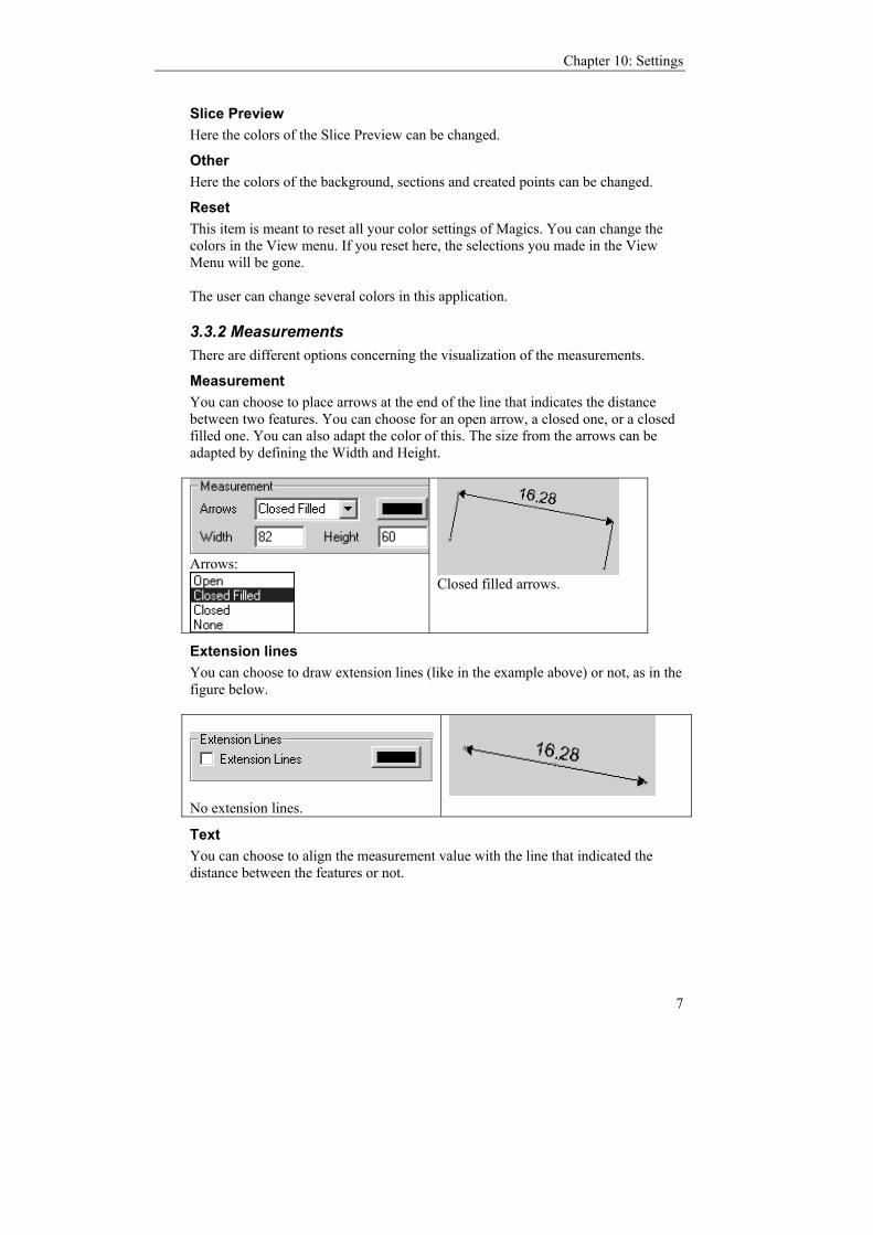
Chapter 10: Settings
7
Slice Preview Here the colors of the Slice Preview can be changed.
Other Here the colors of the background, sections and created points can be changed.
Reset This item is meant to reset all your color settings of Magics. You can change the colors in the View menu. If you reset here, the selections you made in the View Menu will be gone. The user can change several colors in this application.
3.3.2 Measurements There are different options concerning the visualization of the measurements.
Measurement You can choose to place arrows at the end of the line that indicates the distance between two features. You can choose for an open arrow, a closed one, or a closed filled one. You can also adapt the color of this. The size from the arrows can be adapted by defining the Width and Height.
Arrows:
Closed filled arrows.
Extension lines You can choose to draw extension lines (like in the example above) or not, as in the figure below.
No extension lines.
Text You can choose to align the measurement value with the line that indicated the distance between the features or not.

Magics RP Reference Manual
8
Measurement value is aligned.
Measurement value is not aligned.
Grips When you select a measurement, some grips (rounds) will appear on the measurements lines. They allow changing the position of the measurement lines. The grip (1 in the figure) on the intersection of the line that indicates the length and an extension line allows you to turn the former around the axis between the features. The grip (2 in the figure) in the middle of the line that indicates the length allows you to extend or shorten the extension lines. The grips (3 in the figure) that mark the feature (in the case shown below it is a point), can be dragged to the same feature (in this case a point), positioned somewhere else on the part. The measurement value will be adapted. You can define the size of the grip and its color.
Features When you have selected a feature (snap to it and clicked on the right mouse button), you can choose to mark the feature or not.
A point is indicated with a cross, a line and a circle will be colored in the selected color, the axes of a cylinder will be drawn and the contours of its two discs will be colored in the indicated color, a sphere will be marked with three circumpolar circles.
3.3.3 Wireframe A line of the wireframe is drawn when the angle between 2 triangles is exceeding a certain value. The default value is 30°. Here, you can adjust this value.
12
3

Chapter 10: Settings
9
3.3.4 Lighting With these settings, the overall lighting properties of the working screen can be changed.
Ambient. This is the reaction to the ambient light that exists everywhere in the scene, this light is scattered equally in all directions on the surface. Diffuse. This is the reaction to directional light, it reflects more in one direction. Specular. How the material exhibits highlights.
3.3.5 Renderer Modern video cards are having specialized hardware on board to make rendering faster. Magics can use OpenGL and Direct 3D if you have such a card. This will make rendering a lot faster because the CPU is not specialist in rendering and a 3D card is.
Remark: We recommend that you try each mode and see what the results are. Not only the hardware is important, but also the drivers. If you're having problems, try again with other (more recent) drivers.
Software This renderer is the default renderer of Magics, written by Materialise. The rendering is a part of the program and is so done by the CPU. If you do not have a special 3D-videocard or good drivers, we recommend you to use this setting.
Normal: The whole rendering process is done by Magics DirectDraw: some instructions of Microsoft DirectDraw are used to speed up the rendering
OpenGL OpenGL was developed for CAD purposes and using the HW-acceleration present on the card. If a certain feature is not supported by your 3D-card, the OpenGL-driver will perform that specific instruction via software rendering (software fallback).

Magics RP Reference Manual
10
Generic implementation: A render mode that uses a 100% software implementation of OpenGL Hardware accelerated: This mode of OpenGL will use the supported HW-acceleration on the 3D-card. When the card does not support a feature, OpenGL will fallback on software rendering Disable frame cash: Select this setting when you experience problems on high-end OpenGL-cards.
Direct 3D Direct 3D is a part of Microsoft’s Direct X. Direct X was originally developed for 3D games but D3D is also useful for us. When a feature is not implemented on the 3D-card, the D3D can't fallback on software rendering, so the instruction won't be done. Direct3D is NOT supported on Win NT.
Reference Rasterizer: A software simulation of D3D (all the instructions are processed by the CPU in stead of the card). Hardware accelerated: D3D uses the hardware acceleration present on the videocard. Use indexed vertex buffers: Disable the option if you experience problems with smooth shading using the Direct 3D renderer. (e.g. ATI 8500 graphics card)
Background information The principle (roughly) is that the computer sends the triangles to the memory of the video card and the card will do the rendering of the part, following the instructions of Magics. This has directly 2 consequences: 1/ To have optimal results, the memory on the video card must be big enough. (1 MB STL needs approx. 1,5MB ram on the 3D-card) 2/ Each time the part has been changed, the whole list of triangles must be send again to the card. This can cause delays, off course the delays are depending of the size of the part.
Recommendations Out of experience, we can suggest: - GeForce-chipsets are reported to work fine and are powerful. A GeForce-chipset can't do a section with hide front in hardware mode, so it won't work in D3D. It

Chapter 10: Settings
11
will work in OpenGL because OpenGL will fallback to software rendering for displaying a section with hide front. - ATI Radeon cards are also reported to work fine and offer a good performance.. An advantage is that the section hide front is supported in hardware acceleration. - The chipsets KyroII and PowerVR are not recommended due compatibility problems with Magics. We suggest to have at least 32MB memory on the card (the bigger the parts, the more memory is necessary to have top performance). We estimate that for each MB STL-file you will need 1,5 MB RAM on the video card. Remark: A lot is depends on the drivers you installed. In fact we are outsourcing the rendering to the video card. What happens there is out of our control. If you do not use good drivers, the rendering can be strange. So please check if you are using the latest drivers or try different versions when you have problems. You can always use the software rendering in case of problems.
Smooth shading In the Open-GL or Direct 3D render mode (settings - renderer), the part can be visualized using smooth shading. The variations in color will now be shown more gradually and not longer as separate triangles. Note that only the visualization of the part changes, the number of triangles and the accuracy of the stl are not changed.
Use material editor OFF: When you click on the colored round in the selection list or part list sheet (see Menubar/Edit/Part List sheet), a color palette appears. ON: When you click on the colored round in the selection list or part list sheet (see Menubar/Edit/Part List Sheet), the material editor dialog appears. Besides the color, you can here also select the material properties. The colors can be described in 2 ways: RGB (red, green, Blue) and HLS (Hue, Lightness, Saturation).
3.4 File I/O
3.4.1 Working folder
Application working folder You can browse by clicking on the folder icon and set a folder as default folder.

Magics RP Reference Manual
12
Option 1: Magics always proposes this folder when a part needs to be loaded or saved. Option 2: Magics proposes this folder the first time when a part needs to be loaded or saved. The next time, he proposes the last selected folder.
User Profiles A user profile is a file that contains all the settings of the settings menu. Each Magics user can use different settings. To avoid that you each time have to reset your settings when another user has changed them, you can save them as a user profile. These files have the extension .xml. They are default saved in the folder C:/magics profiles. You can change the folder by clicking on the folder icon on the right, browsing and selecting a location.
Import: You can import a user profile from a certain location and place it in the folder chosen. Export: You can export a user profile to a certain location. Save Profile As: You can save a profile: the current settings will be written in a .xml file that will be saved in the folder chosen. Delete: You can delete a profile.
Logging Magics keeps a log file. In this file all operations and actions you do are written (See Menubar/View/Log Window).
Here you can define where you like to save the log file. You can choose the folder by clicking on the folder icon on the right, browsing and selecting a folder. If you choose to limit the log folder size, you can set the maximum size. If the size is reached, the first actions of the Magics session will be erased, so that the latest actions can be written in the file.

Chapter 10: Settings
13
3.4.2 File association
This menu offers you the choice if STL- and MGX-files should be associated to Magics. You can also make Magics check this association each time when Magics is started. When the association is not there anymore, the user will be prompted.
3.4.3 Import
Import Iges and VDA In this dialog box can set that you wish to use Materialise IGES-import or a third party IGES-import like Brock Rooneys. In case of a third party IGES-import, you should mention the path of the translation program.
Load STL options This tool gives you the opportunity to deal with double triangles in a quick way. Identical triangels have their normal in the same direction. Opposite Triangles have their normal in opposite directions. The same option is available as a tool in the Tools Menu (See Menubar/Tools/Remove Double Triangles). The difference is that the settings parameters are saved, and the removal is done automatically during import.
3.4.4 Export (Save colors in stl) When this option is checked, the parts will by default be saved as colored stl (See Menubar/Tools/Paint Part)
3.5 View
3.5.1 Toolbars
Toolbars Magics has four bars: The Main toolbar, the View toolbar, the Mark toolbar and the Status bar. Small toolbars: You can choose do make the Mark and View toolbar smaller. If you mark this option, the toolbars will be smaller the next time you start Magics. Dock Toolbars: Toolbars for marking and visualization can be positioned at the left or at the bottom of the screen (docked).

Magics RP Reference Manual
14
Remark: You can also drag the toolbars and display them as separate window.
Toolsheets Magics has four sheets: The View Toolsheet, the Measure Toolsheet, the Fix Toolsheet and the Part List Sheet. Options Toggle Toolsheets: Three toolsheets are displayed on the screen at start-up. When you like to display the 3rd one, another will disappear. All Toolsheets: All toolsheets. are displayed on the screen. Remark: You can also drag the toolbars and display them as separate window
Remark The standard settings are Toolbars Left and All Toolsheets. If you are working in a low-resolution mode (laptop) of 640*480 or 800*600, it's better to choose Toolbars bottom and Toggle Toolsheets.
3.5.2 Autospin The autospin function will make the parts on the screen rotate automatically. Once started, the parts will keep on rotating. To start the automatics spinning of the part, select the autospin option in the settings menu, and slide over the part with the mouse while keeping the right mouse button down. When the mouse button is released, the part will keep on rotating, its rotation speed is dependent on the speed of the initiating movement. To stop the spinning, click on the part. The key combinations RMB + tab can also be used to start and end the autospin, even if the setting autospin is off.
3.6 Button Reset default settings This button restores all the default settings, including those concerning the printer settings. If you have a problem with printing, it is advised to use this function. Remark: Pay attention because ALL your registry-settings concerning Magics will be erased. The Window will be set to size 800x600 if it's not maximized.
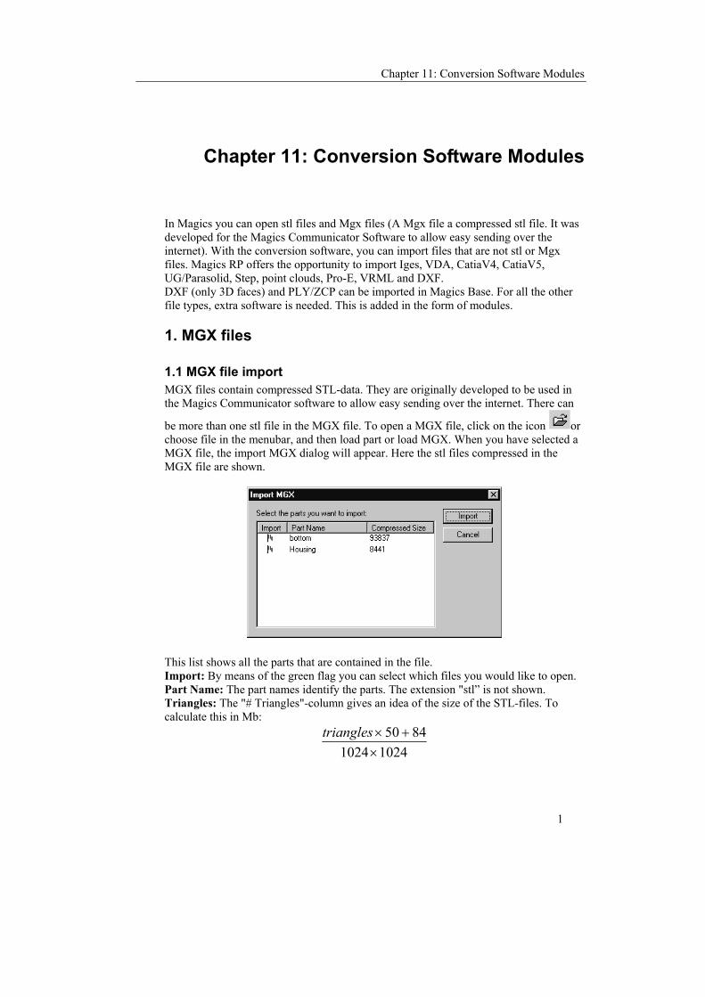
Chapter 11: Conversion Software Modules
1
Chapter 11: Conversion Software Modules
In Magics you can open stl files and Mgx files (A Mgx file a compressed stl file. It was developed for the Magics Communicator Software to allow easy sending over the internet). With the conversion software, you can import files that are not stl or Mgx files. Magics RP offers the opportunity to import Iges, VDA, CatiaV4, CatiaV5, UG/Parasolid, Step, point clouds, Pro-E, VRML and DXF. DXF (only 3D faces) and PLY/ZCP can be imported in Magics Base. For all the other file types, extra software is needed. This is added in the form of modules.
1. MGX files
1.1 MGX file import MGX files contain compressed STL-data. They are originally developed to be used in the Magics Communicator software to allow easy sending over the internet. There can
be more than one stl file in the MGX file. To open a MGX file, click on the icon or choose file in the menubar, and then load part or load MGX. When you have selected a MGX file, the import MGX dialog will appear. Here the stl files compressed in the MGX file are shown.
This list shows all the parts that are contained in the file. Import: By means of the green flag you can select which files you would like to open. Part Name: The part names identify the parts. The extension "stl” is not shown. Triangles: The "# Triangles"-column gives an idea of the size of the STL-files. To calculate this in Mb:
102410248450
×+×triangles

Magics RP Reference Manual
2
Remark: Since these MGX-files contain compressed STL-data, with compression rates up to 15 times, the MGX file-type can be used as STL-zip format.
1.2 Magics file export Magics can convert stl files to MGX files, or can even ‘zip’ different stl files in one MGX file. If you choose file in the menubar and then ‘export magics’ the Export MGX dialog will appear. Here all the files loaded in Magics are shown. By means of a green flag you can choose which stl files you would like to include in the Magics file.
This list shows all the parts that are contained in the file. Export: You can select the files you would like to add in the Mgx file. Part Name: The part names identify the parts. Optional Password: The password is used for encryption so you can send these files safely over the Internet. Self- Extracting: If you select this option, the file will be saved as an executable file. The file will be saved somewhere on your computer. If you look for this file in the directory, and you click on it, the stl files saved in this self-extracting MGX file will be extracted automatically and saved in the same directory. It is handy if you have to send big stl files over the internet to a person who has software that can only read stl files. If you click export a dialog will appear where you can browse to the place where you want the MGX-file to be written and where you can type the desired filename. Remark: Since these MGX-files contain compressed STL-data, with compression rates up to 15 times, the MGX file-type can be used as STL-zip format.
2. Settings for Iges and VDA import Menu: Settings/ Preferences/ File I/O/ Import/ Iges and VDA

Chapter 11: Conversion Software Modules
3
Triangulation Algorithm We offer two triangulation possibilities. This option can also be chosen in the dialog box that pops up whenever you import Catia 4 and 5, Step and UG/ Parasolid . It is advised to use the second.
Import Iges/ Import VDA In this dialog you can choose whether you like to use Materialise software or Third Party software for IGES/VDA conversion. In case of third party software, Magics needs to know the path of this software (only if it can be run from Magics).
3. IGES files
3.1 Import Iges settings See above.
3.2 Materialise IGES Import Main Menu/File/Import IGES Choose and select the IGES-file you like to translate and click on Open. The Iges Import dialog will appear where you have to fill in a few parameters.

Magics RP Reference Manual
4
Input/Output File The name of the input- and output-file can be changed by pushing the buttons to the right of the filenames. If the IGES-file is saved in other units than the active one, the unit conversion will be done automatically. For example, if you are working in mm and you receive an inch-IGES-file, Magics will convert automatically to mm. The accuracy and stitch parameters can be entered in the units you are working in. This means you do not need to be aware of the real units of the IGES-file. Magics converts everything for you.
Triangulation algorithm You have the possibility between 2 algorithms to triangulate the CAD file. It is advised to use version 2. Version 1 however, may do better in some cases. You can also preselect the choice in the Settings: Menu: Settings/ Preferences/ File I/O/ Import/ Iges and VDA
Accuracy IGES is a description of elements of a drawing. Curves can be described as curves. STL is based on triangles. A curve becomes a polyline. The accuracy parameter will define how tight the polyline will be to the original curve. Remark: One would tend to use a very small accuracy but be aware that very small accuracies lead to a huge amount of triangles and thus to a file that needs a lot of RAM.
Make all Entities visible In CAD packages, you can make certain entities invisible. When you transfer the drawing to STL you can ask Magics to make these entities visible nonetheless by choosing the Make all Entities visible-option. Some entities, known as Constructing entities, for example datum planes, will never be converted to STL.

Chapter 11: Conversion Software Modules
5
Fixing Because not all CAD-systems write correct IGES-files, Magics optionally corrects the usual errors. You do not need to be aware of the original units of the IGES-file. The fixing unit of the IGES-converter is the same as the regular fixing unit of Magics. This means that a stitch tolerance that is too big, might destroy the shape of your part, as explained in stitching. Remark: Transferring the IGES-shapes to the STL-triangles induces gaps. The gaps are always smaller than the accuracy but on the other hand they can be as large as the accuracy. So when stitching you might have to raise the stitch tolerance until the accuracy value.
3.3 Problems 1. If you get the following dialog box:
You have, in your settings, marked the 3rd party software in stead off the Materialise import. To solve this go to the settings menu (Menubar / Settings/ Preferences/ FileI/O/ Iges and VDA). 2. If the program seems to hang on the IGES-conversion, try without fixing. IGES-files could be so bad that fixing takes a long time.

Magics RP Reference Manual
6
4. Materialise VDA Import
4.1 Import VDA settings See above
4.2 Import VDA In Magics RP choose Main Menu/File/Import VDA and select the VDA-file you want to translate. Now Magics asks you for a few parameters.
Triangulation algorithm You have the possibility between 2 algorithms to triangulate the CAD file. It is advised to use version 2. Version 1 however, may do better in some cases. You can also preselect the choice in the Settings: Menu: Settings/ Preferences/ File I/O/ Import/ Iges and VDA
Input/Output File The name of the input- and output-file can be changed pushing the buttons to the right of the filenames. If the VDA-file is saved in other unit than the active one in Magics, the unit conversion will be done automatically. For example, if you are working in mm and you receive an inch-VDA-file, Magics will convert automatically to mm. The accuracy and stitch parameters can be entered in the units you are working in. This means you needn't be aware of the real units of the VDA-file. Magics converts everything for you.

Chapter 11: Conversion Software Modules
7
Accuracy VDA is a description of elements of a drawing. Curves can be described as curves. STL is based on triangles. A curve becomes a polyline. The accuracy parameter will define how tight the polyline will be to the original curve. Remark: One would tend to use a very small accuracy but be aware that very small accuracy's lead to a huge amount of triangles and thus to a file that needs to much of RAM.
Fixing Because not all CAD-systems write correct VDA-files, Magics optionally corrects the usual errors. You shouldn't be aware of the original units of the VDA-file. The fixing unit of the VDA-converter is the same as the regular Fixing unit of Magics. This means that a stitch tolerance that is too big, might destroy the shape of your part, as explained in stitching. Remark: Transferring the VDA-shapes to the STL-triangles induces gaps. The gaps are always smaller than the accuracy but on the other hand they can be as large as the accuracy. So when stitching you might have to raise the stitch tolerance until the accuracy value.
4.3 Problems 1. If you get the following dialog box:
You have, in your settings, marked the 3rd party software in stead off the Materialise import. To solve this got to the settings menu.(Menubar / Settings/ Preferences/ FileI/O/ Iges and VDA). 2. If the program seems to hang on the VDA-conversion, try without fixing. VDA-files could be so bad that fixing takes a long time.
5. Catia V4Import
5.1 Versions supported Versions 4.1.5 till 4.2.4 are supported.
5.2 Way of working Main Menu/File/Import Catia

Magics RP Reference Manual
8
Choose the Catia-file you want to translate. You can choose for Export-files as well as for Model-files by changing the file-type as shown in the following figure.
Now Magics asks you for a few parameters.
Input/Output File The name of the input- and output-file can be changed by pushing the buttons to the right of the filenames. If the Catia-file is saved in other unit than the active one, the unit conversion will be done automatically. For example, if you are working in mm and you receive an inch-Catia-file, Magics will convert automatically to mm. The accuracy and stitch parameters can be entered in the units you are working in. This means you needn't be aware of the real units of the Catia-file. Magics converts everything for you.
Triangulation algorithm You have the possibility between 2 algorithms to triangulate the CAD file. It is advised to use version 2. Version 1 however, may do better in some cases. You can also preselect the choice in the Settings: Menu: Settings/ Preferences/ File I/O/ Import/ Iges and VDA
Accuracy Catia is a description of elements of a drawing. Curves can be described as curves. STL is based on triangles. A curve becomes a polyline. The accuracy parameter will define how tight the polyline will be to the original curve. Remark: One would tend to use a very small accuracy but be aware that very small accuracy's lead to a huge amount of triangles and thus to a file that needs too much of RAM.
Make all Entities visible In CAD packages, you can make certain entities invisible. When you transfer the drawing to STL you can ask Magics to make these entities visible nonetheless by choosing the Make all Entities visible-option. Some entities, known as Constructing entities, for example datum planes, will never be converted to STL.

Chapter 11: Conversion Software Modules
9
Fixing Because not all CAD-systems write correct Catia-files, Magics optionally corrects the usual errors. You shouldn't be aware of the original units of the IGES-file. The fixing unit of the Catia-converter is the same as the regular Fixing unit of Magics. This means that a stitch tolerance that is too big, might destroy the shape of your part. Remark: Transferring the Catia-shapes to the STL-triangles induces gaps. The gaps are always smaller than the accuracy but on the other hand they can be as large as the accuracy. So when stitching you might have to raise the stitch tolerance until the accuracy value.
Model List Since Catia files can consist out of several parts (the file is an assembly), you can choose the parts to convert. In the example above the part is called "CVDEMO" Remark: At least one model (part) should be chosen.
Catia Layers Catia works with layers. This conversion software offers you the opportunity to select the layers you want to be converted.
To indicate from which layers you want the entities to be created, select the appropriate layer from the upper list, push the Add filter to list-button and the layer number will be added in the bottom list. Repeat this action until al layers you want to convert entities from, appear in the bottom list. Then push OK.
5.3 Problem If the program seems to hang on the Catia-conversion, try without fixing. Catia-files could be so bad that fixing takes a long time.
6. Catia V5 import
6.1 Versions supported For *.Catpart: from 5.6 till 5.12 For *.Catproduct: from 5.7 till 5.12
Magics RP Reference Manual
10
6.2 Way of working Main Menu/File/Import Catia V5 Choose and select the Catia-file you want to translate. Now Magics asks you for a few parameters. Way of working
Input/Output File The name of the input- and output-file can be changed by pushing the buttons to the right of the filenames. If the Catia V5-file is saved in other unit than the active one, the unit conversion will be done automatically. For example, if you are working in mm and you receive an inch-file, Magics will convert automatically to mm. The accuracy and stitch parameters can be entered in the units you are working in. This means you needn't be aware of the real units of the Catia V5-file. Magics converts everything for you.
Triangulation algorithm You have the possibility between 2 algorithms to triangulate the CAD file. It is advised to use version 2. Version 1 however, may do better in some cases. You can also preselect the choice in the Settings: Menu: Settings/ Preferences/ File I/O/ Import/ Iges and VDA
Accuracy Catia V5 is a description of elements of a drawing. Curves can be described as curves. STL is based on triangles. A curve becomes a polyline. The accuracy parameter will define how tight the polyline will be to the original curve. Remark: One would tend to use a very small accuracy but be aware that very small accuracy's lead to a huge amount of triangles and thus to a file that needs to much of RAM.
Make all Entities visible In CAD packages, you can make certain entities invisible. When you transfer the drawing to STL you can ask Magics to make these entities visible nonetheless by choosing the –option. Some entities, known as Constructing entities, for example datum planes, will never be converted to STL.
Fixing Magics optionally corrects the usual errors. You shouldn't be aware of the original units of the file. The fixing unit of the Catia V5-converter is the same as the regular Fixing unit of Magics. This means that a stitch tolerance that is too big might destroy the shape of your part. Remark: Transferring the Catia V5-shapes to the STL-triangles induces gaps. The gaps are always smaller than the accuracy but on the other hand they can be as large as the accuracy. So when stitching you might have to raise the stitch tolerance until the accuracy value.
6.3 Problem If the program seems to hang on the Catia V5-conversion, try without fixing. Catia V5-files could be so bad that fixing takes a long time.
Chapter 11: Conversion Software Modules
11
7. Step import
7.1 Versions supported Versions AP 214 and AP 203 are supported.
7.2 Way of working Main Menu/File/Import STEP Choose and select the STEP-file you want to translate. Now Magics asks you for a few parameters.
Input/Output File The name of the input- and output-file can be changed by pushing the buttons to the right of the filenames. If the Step-file is saved in other unit than the active one, the unit conversion will be done automatically. For example, if you are working in mm and you receive an inch-file, Magics will convert automatically to mm. The accuracy and stitch parameters can be entered in the units you are working in. This means you needn't be aware of the real units of the Step-file. Magics converts everything for you.
Triangulation algorithm You have the possibility between 2 algorithms to triangulate the CAD file. It is advised to use version 2. Version 1 however, may do better in some cases. You can also preselect the choice in the Settings: Menu: Settings/ Preferences/ File I/O/ Import/ Iges and VDA
Accuracy Step is a description of elements of a drawing. Curves can be described as curves. STL is based on triangles. A curve becomes a polyline. The accuracy parameter will define how tight the polyline will be to the original curve. Remark: One would tend to use a very small accuracy but be aware that very small accuracy's lead to a huge amount of triangles and thus to a file that needs to much of RAM.
Make all Entities visible In CAD packages, you can make certain entities invisible. When you transfer the drawing to STL you can ask Magics to make these entities visible nonetheless by choosing the –option. Some entities, known as Constructing entities, for example datum planes, will never be converted to STL.
Fixing Magics optionally corrects the usual errors. You shouldn't be aware of the original units of the file. The fixing unit of the Step-converter is the same as the regular Fixing unit of Magics. This means that a stitch tolerance that is too big might destroy the shape of your part. Remark: Transferring the Step-shapes to the STL-triangles induces gaps. The gaps are always smaller than the accuracy but on the other hand they can be as large as the

Magics RP Reference Manual
12
accuracy. So when stitching you might have to raise the stitch tolerance until the accuracy value.
7.3 Problem If the program seems to hang on the Step-conversion, try without fixing. Step-files could be so bad that fixing takes a long time.
8. Materialise Unigraphics Import
8.1 Version supported Versions V15 till UGNX 2 are supported.
8.2 Way of working Main Menu/File/Import Unigraphics Choose and select the Unigraphics-file you want to translate. Now Magics asks you for a few parameters.
Input/Output File The name of the input- and output-file can be changed by pushing the buttons to the right of the filenames. If the Unigraphics-file is saved in other unit than the active one, the unit conversion will be done automatically. For example, if you are working in mm and you receive an inch-file, Magics will convert automatically to mm. The accuracy and stitch parameters can be entered in the units you are working in. This means you needn't be aware of the real units of the Unigraphics-file. Magics converts everything for you.
Triangulation algorithm You have the possibility between 2 algorithms to triangulate the CAD file. It is advised to use version 2. Version 1 however, may do better in some cases. You can also preselect the choice in the Settings: Menu: Settings/ Preferences/ File I/O/ Import/ Iges and VDA
Accuracy Unigraphics is a description of elements of a drawing. Curves can be described as curves. STL is based on triangles. A curve becomes a polyline. The accuracy parameter will define how tight the polyline will be to the original curve. Remark: One would tend to use a very small accuracy but be aware that very small accuracy's lead to a huge amount of triangles and thus to a file that needs to much of RAM.
Make all Entities visible In CAD packages, you can make certain entities invisible. When you transfer the drawing to STL you can ask Magics to make these entities visible nonetheless by choosing the –option. Some entities, known as Constructing entities, for example datum planes, will never be converted to STL.

Chapter 11: Conversion Software Modules
13
Fixing Magics optionally corrects the usual errors. You shouldn't be aware of the original units of the file. The fixing unit of the Unigraphics-converter is the same as the regular Fixing unit of Magics. This means that a stitch tolerance that is too big, might destroy the shape of your part. Remark: Transferring the Unigraphics-shapes to the STL-triangles induces gaps. The gaps are always smaller than the accuracy but on the other hand they can be as large as the accuracy. So when stitching you might have to raise the stitch tolerance until the accuracy value.
8.3 Problem If the program seems to hang on the Unigraphics-conversion, try without fixing. Unigraphics-files could be so bad that fixing takes a long time.

Magics RP Reference Manual
14
9. Pro Engineer Import
9.1 Versions supported Versions V16 till ProE 2001 are supported.
9.2 Way of working Main Menu/File/Import Pro/E Choose and select the Pro/E-file you like to translate. Now Magics asks you for a few parameters.
Input/Output File Pushing the buttons to the right of the filenames can change the name of the input- and output-file. If the Pro/E-file is saved in other unit than the active one, the unit conversion will be done automatically. For example, if you are working in mm and you receive an inch-file, Magics will convert automatically to mm. The accuracy and stitch parameters can be entered in the units you are working in. This means you needn't be aware of the real units of the Pro/E-file. Magics converts everything for you.
Triangulation algorithm You have the possibility between 2 algorithms to triangulate the CAD file. It is advised to use version 2. Version 1 however, may do better in some cases. You can also preselect the choice in the Settings: Menu: Settings/ Preferences/ File I/O/ Import/ Iges and VDA
Accuracy Pro/E is a description of elements of a drawing. Curves can be described as curves. STL is based on triangles. A curve becomes a polyline. The accuracy parameter will define how tight the polyline will be to the original curve. Remark: One would tend to use a very small accuracy but be aware that very small accuracy's lead to a huge amount of triangles and thus to a file that needs to much of RAM.
Make all Entities visible In CAD packages, you can make certain entities invisible. When you transfer the drawing to STL you can ask Magics to make these entities visible nonetheless by choosing the –option. Some entities, known as constructing entities, for example datum planes, will never be converted to STL.
Fixing Magics optionally corrects the usual errors. You shouldn't be aware of the original units of the file. The fixing unit of the Pro/E-converter is the same as the regular Fixing unit of Magics. This means that a stitch tolerance that is too big, might destroy the shape of your part. Remark: Transferring the Pro/E-shapes to the STL-triangles induces gaps. The gaps are always smaller than the accuracy but on the other hand they can be as large as the

Chapter 11: Conversion Software Modules
15
accuracy. So when stitching you might have to raise the stitch tolerance until the accuracy value.
9.3 Problem If the program seems to hang on the Pro/E-conversion, try without fixing. Pro/E-files could be so bad that fixing takes a long time.
10. Materialise Pointcloud Import
10.1 General A pointcloud is a group of points retrieved by scanning a part. Magics will read the file containing the coordinates of these points and will create triangles using the scanned points. In this way, the pointcloud is triangulated.

Magics RP Reference Manual
16
10.2 Parameter menu
10.2.1 File The name of the file contains the coordinates of the points. This must be an ASCII text file. Each line contains a point, described in an X, Y and Z coordinate, separated by a space. Type: because there are some variations to the ASCII format, you can choose the right variation. When automatic is set, Magics will detect this automatically.

Chapter 11: Conversion Software Modules
17
Parameter set
This is to load and save parameter sets. Once you discovered good values for the parameters, it might be useful to save them and load them when needed. Predefined This is a list of all the predefined parametersets, you can
select a parameter set over here New To create a new set of predefined parameters Update to save the current parameters into the current selected
parameter set Delete to delete a predefined parameter set Default So the current parameter set will become the default
parameter set Last Used Last Used will take the parameters you used the last time
for triangulation
Estimate The estimate button will scan the list of points and give an estimation of the values you should use to get a good triangulation. To get a better estimation of the parameters, the user can input what kind of pointcloud Magics will be reading. The part dimensions will give you an impression of the size. In the columns you can read the values for X, Y and Z, in the rows you can read the smallest and the biggest value Magics found for this axis.
Parameters Hole filling Strength (%) Larger values avoid holes in the surface, but too
large values may give undesired connections of surfaces.
Noise filling strength (%) The higher, the more noise will be removed (= points

Magics RP Reference Manual
18
that do not contribute to any surface because they have almost no neighbor). Too small values will create spikes and bad surfaces in noisy files. Too big values may remove points in low density areas and thus create holes.
Sharpening strength (%) The surfacer tries to smooth the file to reduce the effect of noise. The refinement will compensate this and attempt to sharpen the result so that sharp edges are preserved.
Spacer If the Spacer checkbox is checked, the uniform reduction of the amount of points will be done.
Maximum number of points (#) The maximum amount of points used in the resulting STL-file. This number will have as well an immediate effect on the number of triangles used. If there are more points in the file, the amount of points will be reduced with a uniform reduction
Scale coefficient Factor for scaling the resulting part. The user should select if the coordinates are in inch or mm, because the pointcloud file does not contain this information. The user can also scale the pointcloud manually.
Advanced Neighborhood points (#) A higher value will result in a higher density
pointcloud, a lower value will yield a lower density pointcloud.
Threshold angle (°) The algorithm will try to avoid that in the resulting surface angles are made which are smaller than the specified value.
Noise filter threshold (#) Clusters with less points than the threshold value will be removed
Filter strength (%) The higher the value, the smoother the part will be. (Too big values will reduce the accuracy)
Number of filter iterations (#) How many times the filter algorithm should be applied.
Sharp refinement To preserve sharp edges (meant for mechanical parts)

Chapter 12: Magics RP Base Tutorial
1
Chapter 12: Magics RP Tutorial
1. Visualization Tutorial The file used is found in the directory../Magics RP .../demo_files and is called "Good.stl".
To load a file do 'Ctrl + L' or use the icon. You can now browse the network. Look for files of the STL format.
A file can be displayed in different view modes (View Toolsheet)
Try these modes.
You have camera control with the 'F4'-button or with the icon. Drag over the part and see how the part rotates.
• When the cursor is near the middle of the window it will have a quadruple
arrow shape , the movement of the cursor is translated in a rotation around the axes of the screen.
• When the cursor is near the borders of the window it will have circular arrow
shape , the part can be rotated around an axis perpendicular to the screen.
For fast orientation use the default views . This can be found on the Rotate-tab of the view toolsheet.

Magics RP Reference Manual
2
Seven Default views are predefined: Front, Back, Left, Right, Top, Bottom and ISO view. These views can be accessed by clicking on one of the arrows (they will highlight when the cursor passes over it). The ISO view is selected when all borders of the box are highlighted (click in the purple area, or on the borders).
With the icon, you can move the part in the window plane by dragging the part with the cursor (keep left mouse button down). This function can also be accessed via Main Menu/View/Pan or with the hotkey 'Alt + M'. Use SECTIONS to inspect the inside of the part. Sections can be found on the Sections-tab of the view toolsheet.
You can have sections perpendicular to the X, Y and Z-axis. You can hide the front and give the part a hollow display.
2. Fixing This tutorial is used to introduce some of the STL-fixer tools. Fixing a part is done at two levels, there are global actions which are performed on the entire part and actions done locally on the part. The global fixing (first level) is totally automatic and involves :
1. Automatic fixing of bad normals
2. Automatic fixing of bad edges (stitching)
The next level is fixing the remaining local errors, one by one.:
3. Fixing of remaining errors (double surfaces, fill holes, trim surfaces...)
After all bad triangles and bad edges are corrected; the part will be fixed to 1 coherent part.
4. Uniting shells
It can be that at some points in this Tutorial, you can fix in another way than is described. This could result in other amounts of bad edges and bad contours or in other looks at the part.
2.1 Loading the part 1. Before a part is loaded you have to set the correct units (Main Menu/Tools/Settings). The units of this demo part are in mm.

Chapter 12: Magics RP Base Tutorial
3
load the STL-file "Bad.stl" (Main Menu/File/Load Part). The following part will be displayed.
2.2 Automatic Fixing of Bad Normals At first sight, the part is full of holes. However, when we select flipped triangles from the Mode Tab on the view toolsheet, the total part becomes visible, the flipped triangles are colored red.
3. A triangle is defined to have two colors: the front side is colored gray, the backside is colored red. A perfect part always looks gray at the outside. The inside of a perfect part (look at a cross section of the part) is colored red. Flipped triangles are triangles who show their back instead of their front and are thus displayed in red. To be sure that the hatching will be done correctly the flipped normals have to be inverted. The normals of the flipped triangles can be inverted automatically with
on the fix toolsheet/tab fix normals or with the option from the automatic fixing sheet.
What remains red after the inversion is:

Magics RP Reference Manual
4
• gaps ( you see the inside of the part which is colored red)
• a plane where there shouldn't be one (due to bad trimming of the fillets)
• double surfaces
• intersection of shells
• triangles the program did not flip or were flipped incorrectly
These errors need to be solved one by one: fixing of the remaining errors
2.3 Automatic Fixing of Bad Edges Select the bad edges-option on the view toolsheet. All bad edges are displayed in yellow.
The user can hide the bad edges that are situated behind or inside the part. To do so, he has to indicate the hidden line checkbox. When looking at the part-properties (push
) we can see that this part has 11 652 bad edges and 340 bad contours. 5. A triangle shares every edge with just one other triangle. Errors occur when an edge hasn't a neighbor (triangle next to a gap) or one edge has more than one neighbor. When there are bad edges, there may occur problems with the hatching. These problems are solved with stitching. In general, saving (Main Menu/File/Save As...) an intermediate result of the fixing is strongly advised because fixing a corrupted STL-file is in many cases a work of trial and error. Especially stitching with a high tolerance can damage the part. Stitch (fix toolsheet/tab triangle fixer or tab automatic) with a tolerance of 0.1 MM. In the Automatic-tab you can see there is also an Iterations-parameter.
.

Chapter 12: Magics RP Base Tutorial
5
So in this case the program will stitch in five times (only when you push the -button). To see the effect of the tolerance value, you can try out different
values like 0.001, 0.01 and 0.05 and spot the difference. Check the properties box . You have now 364 bad edges and 10 bad contours. These errors have to be fixed manually.
2.4 Fixing of the remaining errors Further fixing will be done by localizing the errors and fix them as single units.
5. You can manipulate the view of the part by rotating , moving and
zooming in on the part. Manipulate the part so you obtain the same view as the picture below:
7. The inside of the part, which is colored red, is visible at n°1. The hole was too large to be closed with the automatic fixer.
We can fill this hole (Fix Toolsheet/Tab Triangle Fixer) . If you are satisfied
with the filling, unmark (Mark Toolbar) the selection, otherwise you can delete the marked triangles (fix toolsheet/tab triangle fixer) :

Magics RP Reference Manual
6
Another way of filling holes is by drawing yourself every triangle in the hole using
create triangles . When you use this Create, it is advised to update the view
regularly with . 8. The two red spots (n° 2 & 3) indicate two shells with flipped triangles. This is an example of intersection of one shell with another shell. In a later stage we will unite all penetrating shells with a Boolean operation.
You can select this shell by using (Mark Toolbar). To invert the normals of this shell click (fix toolsheet/tab fix normals). 9. A similar case is found at n° 4.
zoom in at n° 4.
Invert this shell like the previous ones. 10. The following errors that will be treated are situated on the following locations :
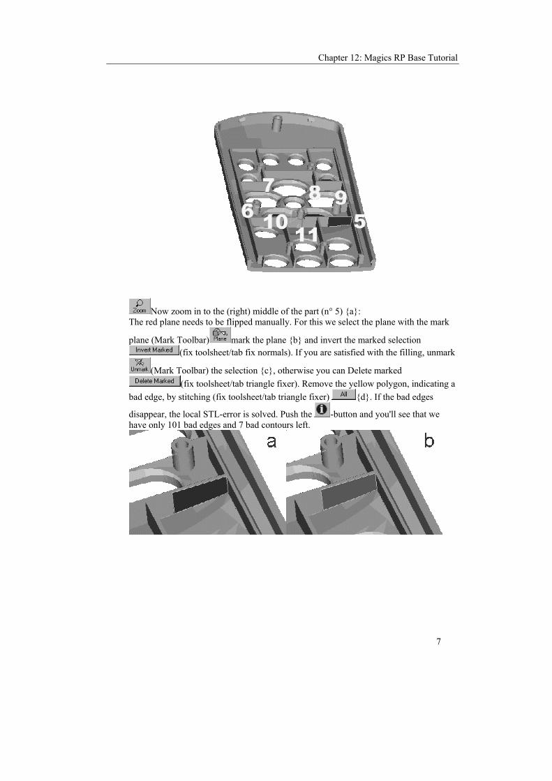
Chapter 12: Magics RP Base Tutorial
7
Now zoom in to the (right) middle of the part (n° 5) {a}: The red plane needs to be flipped manually. For this we select the plane with the mark
plane (Mark Toolbar) mark the plane {b} and invert the marked selection (fix toolsheet/tab fix normals). If you are satisfied with the filling, unmark
(Mark Toolbar) the selection {c}, otherwise you can Delete marked (fix toolsheet/tab triangle fixer). Remove the yellow polygon, indicating a
bad edge, by stitching (fix toolsheet/tab triangle fixer) {d}. If the bad edges
disappear, the local STL-error is solved. Push the -button and you'll see that we have only 101 bad edges and 7 bad contours left.

Magics RP Reference Manual
8
11. Next turn the part and zoom in to local error n° 6.
If you use mark plane (Mark Toolbar), you get the following display:
Sometimes, you can observe an interference pattern between red (or green) and gray surfaces. This is typical in case of double surfaces (two surfaces on top of each other). To fix a double surface, you can remove one of the surfaces or you can remove both surfaces and fill the resulting hole. To fix a double surface, it's advised to remove both surfaces (Mark first and then Delete Marked from the fixing toolsheet/triangle fixer tab) and fill the created hole again with create triangle and/or fill hole. If there is a bad edge due to the double surface, you can use the mark bad edge-function

Chapter 12: Magics RP Base Tutorial
9
Deleting the marked set of triangles, also solves the problem of the double surface
.
Local error 7,8 and 9 can be treated like error 6 (double surfaces). In this cases you have to mark the bad edges and delete the marked set of triangles. For errors 7 and 8 this solves the problem. For nr.9 you'll have to mark the bad edges again and delete the marked selection. All triangles in the double surface are deleted and there is a hole left.
With the fill hole-function, you can solve the errors . Pushing the properties
button ( ) shows that we have now only 63 bad edges and 3 bad contours left. 12. zoom to center and see local error n°10. This is a plane that was incorrectly trimmed.

Magics RP Reference Manual
10
The CAD software has drawn a surface where there shouldn't be one. The plane in red has to be totally removed. Best is to look at the upside of the part (view A). To fix this error we will remove this plane.
If you want to select this plane with a single selection, you have to adjust the plane
selection parameter (Shift + ), the following screen is displayed:
Using mark plane (Mark Toolbar) until the yellow contour is filled with mark triangles. If you set the Plane Selection parameters to high, the marked portion of the part could be to big and delete marked could damage your part as details might get lost.
Then Delete Marked (fix toolsheet/tab triangle fixer) results in:

Chapter 12: Magics RP Base Tutorial
11
Next fill hole (Fix Toolsheet/Tab Triangle Fixer) and unmark (Mark Toolbar) the selection. This local error is solved:
13. Next, the red circle in the middle has to be fixed (local error n° 11). This error is similar as error n° 5.
The red circle needs to be flipped manually. First we reset our plane selection parameters (Settings Menu / Plane Selection Parameters):

Magics RP Reference Manual
12
Than we select the plane with the mark plane (Mark Toolbar) and invert the marked selection (fix toolsheet/tab fix normals). The yellow polygon, indicating a bad edge, can be removed by stitching (fix toolsheet/tab triangle fixer)
with a high tolerance (2 mm). If the bad edges disappear, the local STL-error is solved.
To end the fixing process, stitching with a high tolerance can be done to remove the remaining errors. Again it is advised to save the result as a separate file before stitching takes place. 14. You can check if all local errors are fixed with properties. If the number of bad edges and the number of bad contours are zero, this stage of fixing is done.
2.5 Uniting Shells
15. If you look in the Properties dialog box ( ), and you push the Analyze-button then you'll see you have 6 shells. Push now in the triangle sheet of the fix toolsheet. You now have 6 parts.

Chapter 12: Magics RP Base Tutorial
13
The numbers 2, 3 and 4 are shells that have been flipped before. The central tag is from the part itself. When we zoom in on number 4 and we take a section across the shell we can see the following.
We zoom in a bit more and see that the item was drawn but probably not joined to the part. It floats just next to the part (view a). To solve this problem we first mark the back
plane of the item via (view b).

Magics RP Reference Manual
14
Then we extrude ( ) this plane
over 0.5 mm and we add Triangles in the proposed direction (view c). To join the item
to the part be sure they are the only two parts selected ( ). The use the boolean
feature ( ) to unite the two and the result is what we expected to have out of the CAD-package.
16. The other items have the same problem. The cylinder (shell_2) is already intersecting the main shell. So the cylinder can just be united with the remote controller
by means of a boolean Unite ( ).
3. Nesting STL Files Magics RP can also be used to nest parts on a platform. Select Machine Setup from the File-menu. In the Current Platform window select the name 3D Systems SLA 250. You can customize the machine you work with. The files used are found in the directory ../Magics RP .../demo_files and are called good and bad. Use the CTRL or Shift button to make a multiple selection.
To load a file type Ctrl + L or use the icon. You can now browse the network. Look for files of the STL format. Switch on the option default part position.

Chapter 12: Magics RP Base Tutorial
15
The green tags indicate if a part is selected or not. With or F2 you can alternate the selection by dragging a window, by indicating the tag or by clicking on the part. ONLY SELECTED PARTS CAN BE MANIPULATED
The parts are penetrating. Use automatic placement to reposition the files, or Ctrl +A.
Take a top-view and switch to the mode. The automatic placement is done based on the bounding boxes.
Finer placement is done with Pick&Place, or F3. In this mode, you can choose another Visualization mode independent of the visualization mode outside this mode.
You can also use mode or any other mode.
With Pick&Place, you can select parts , translate them or rotate them .
3.1 Selection In order to translate or rotate parts with pick and place, a selection must first be made! With the selection cursor one ore more parts can be selected. In the pick and place mode is the selection tag the same as the translation tag.
3.2 Translation With the translation cursor, the part can be dragged over the screen. To translate the part , the left mouse button has to be pushed while the cursor points to the tag. If several parts are selected, they will all move by the same translation vector. Depending on the default view or view direction the user is working in, the following translations are possible:
• ISO view or non standard views: translation along X and Y axis
• front and back view: translation along X and Z axis
• left and right view: translation along Y and Z axis
• bottom and top view: translation along X and Y axis
For speeding up the process, the option real-time interaction can be switched off.

Magics RP Reference Manual
16
3.3 Rotation With the rotation cursor, the part can be reoriented. To rotate the part, the left mouse button has to be pushed while the cursor points to one of the corners of the bounding box. If several parts are selected, they will all rotate over the same angle. Depending on the default view the user is working in, the following rotations are possible:
• ISO view or non standard views: rotation over the Z axis
• front and back view: rotation over the Y-axis
• left and right view: rotation over the X axis
• bottom and top view: rotation over the Z axis
4. Manipulating STL Files The file used is found in the directory ../Magics RP .../demo_files and is called "Good.stl".
To load a file do 'Ctrl + L' or use the icon. You can now browse the network. Look for files of the STL format.
Now create a box with dimensions (70, 140, 70). Using the top and the side view, , position the part in the box.
Use the Boolean operation subtract, , to create a cavity.
Next cut the part, , and reposition with Automatic placement, .

Chapter 12: Magics RP Base Tutorial
17

Chapter 13: Troubleshooting
1
Chapter 13: Troubleshooting
1. General
1.1 Installing Magics RP To install on Magics RP on Windows NT, you should be administrator.
1.2 Printing If you have printing problems, try to reduce the resolution from 600 to 300dpi.
1.3 Printing on Windows NT Sometimes printing goes wrong when you are working with Windows NT. The problem is that in some way the parameter Metafile Spooling of your printer settings should be OFF. If you don't know how to check or change that parameter, do the following.
1. In your application (Magics RP) choose File/Print Setup... .
2. Click the Properties-button
3. Go to the advanced-tab. If you don't see Metafile Spooling then go to the '+'-sign in the bottom line and click it.
4. Click the Metafile Spooling line.
5. Click the OFF-option button
If this doesn't improve the printing from Magics, then you should lower the resolution. This parameter is located in the same Advanced-tab. Be careful because the Advanced-tab page can be different for different printers.
1.4 When Magics won't start anymore When you enabled the auto-recovery option it is possible that within a crash this recovery file gets corrupt. When Magics wants to start he will ask if you want to recover. If the recovery-file is corrupt, Magics might not be able to open. Choose not to recover the next time or go to the standard Windows Temporary '\MAGICS RP Undo'-folder and delete the file: rp_autorecovery_#.tmp where # is a number.

Magics RP Reference Manual
2
1.5 Magics hangs Magics uses DirectDraw to accelerate the drawing. We noticed that some videodrivers are not compatible with this feature and causes Magics to hang. To prevent this problem you should go to Settings and switch off Enable DirectDraw.
2. Rapid Tooling Module
2.1 Cutting Parting Planes After cutting the surrounding parting plane, the dimensions of the mold can not be adjusted anymore. Before you separate portions of the surrounding parting plane, you need to have one contour surrounding that plane. So you should make an incision between the outer and inner contour of the surrounding parting surface before you make an incision between nodes of an inner contour of the surrounding parting surface. When the cutting doesn't work and you are working with two or more cavities in one mold, please read the comment on multiple molds.
2.2 Big Files & tooling When you have a large part (order of magnitude of meters) to do tooling on and that file has big triangles (order of magnitude), the tooling module might crash. In such a case you can rescale your part with a factor of 10, do tooling and rescale your mold afterwards to get your part.
2.3 Strange results after projecting a selection If after a projection, Magics pops up a Warning that he isn't in the ability of completing the projection, a few points might be projected however.
3. Conversion Software
3.1 Fixing an Imported IGES-, VDA-, Catia-, .. file If an automatic fixer after the ..-to-STL conversion doesn't remove all errors, you'd better compare the accuracy of your conversion and the stitch-tolerance of the fixer. The stitch-tolerance should at least have the same value as the accuracy of the conversion.
3.2 After import, nothing is visible (IGES and Catia) Sometimes the result of an IGES/Catia conversion is just nothing, you'll see a blank screen after the conversion. If this happens, the main reason is that the IGES/Catia-file was constructed with entities that weren't meant to be shown. So the IGES/Catia convertor doesn't convert these items into the STL-format. To solve this problem, there is an option in the IGES/Catia-convertor dialog box to make all entities visible. When this option is selected, all entities, visible and invisible, will be converted to the STL-format.

Chapter 13: Troubleshooting
3
3.3 DXF conversion doesn't work The DXF-conversion in Magics is a 3D-faces converter. Thus other dxf-files can't be read.
4. 3D-Lightyear There are 2 ways to export the data generated by Magics RP to 3D-lightyear: Using STL-files or SLC-files. Because 3D-LY uses a new SLI-format, the SLI-format generated by Magics RP is not compatible with 3D-Lightyear and thus can not be used.
4.1 Parts The parts can be exported very easily using the STL-format. Just save them in Magics as an STL-file and you'll have no problem when loading the file in 3D-Lightyear.
4.2 Support The supports generated by Magics RP can be exported via an STL-file. You can export the support in Magics as an STL-file. Pay attention, the filename must have the form 'filename_S.STL'. If not, 3D-lightyear won't recognize this STL-file as a support and this will create problems when preparing (Prepare = 3D Lightyear term for Export) the platform in 3D-LY. The configuration files for 3D-systems machines, in the Magics Machine Setup, contain the right settings to use this name-template. If you'd like to export perforated supports you'll have to use the SLC-format because the perforations aren't applied when exporting the support in a STL-format. To gain time when slicing, make sure that the layerthickness that you use in Magics RP is the same one as you use in 3D-LY.
5. Tips & Tricks Normally, measuring can only be done on the wireframe. When a section is defined, however, it is possible to measure everything in that section, even features that do not exist in the wireframe. To get an even better view of the (inner) part, one can use hide front and hollow. This will minimize errors during measurement. The measure functions can be found in the Measure Toolsheet.
5.1 Printing It is very easy to print the part together with measurements and additional information about your STL part. The part can be placed in the desired position on the page, and all indicated measurements will be printed as well. The user can create his own labels with standard STL information (filename, sizes, number of triangles and volume) and user input (e.g. for the client name, remarks etc...). This label will be printed alongside the part. Printing can be done directly via the Print Button, or via Main Menu/File/Print.

Magics RP Reference Manual
4
5.2 Measuring On The Wireframe As it is only possible to measure on the wireframe for 3D measurements (which is deduced from the STL file), and visual misinterpretation of selected features is not unthinkable (several features in the wireframe can lie on top of one another in which case it will be difficult to see which one has been selected). Therefore the shaded & wireframe visualization mode will help you identify all features in the wireframe. (It is, however, also possible to measure in a section which will resolve such ambiguity problems.)
5.3 Measuring In a Section measuring in a section has the advantage of being completely unambiguous in the selection of features. Moreover, features can be recognized more easily in a section than on the wireframe. When creating a section, measurements are automatically restricted to the active section, but this can be switched off at any time in the measure toolsheet. You can change the section at any time during measurements; ALSO in between the selection of several features for one measurement. The section feature can be a very practical way to get more insight in the complete design of an STL part. With the hide front and hollow options, the inner side of the object can be visualized and measured. You can even dynamically browse through the part while dragging the section position slider.
5.4 Several Measurements with a Common feature While measuring, it is possible to indicate an existing (already selected feature) as one of the basic features of the measurement. When this basic feature is changed, all dimensions based on this feature will change accordingly.
5.5 Preview Before Loading In the Open File dialog box (Main Menu/File/Open), it is possible to enable or disable the Preview. When this option is enabled, it is possible to view the STL file before loading it. Just click once on the filename. There are three possibilities:
1. The file is not an STL file (or a corrupted one): this will be indicated.
2. The file is an ASCII file: this will be indicated
3. The file is a valid (binary) STL file: a preview will be shown. The first time a file is indicated, Magics will calculate a preview image. This image will be stored for later use as a .mmp file. Subsequent previews of this file will be immediate.
5.6 Printing and Dithering To have the best representation of the shading of your STL files, always use the finest dithering technique. Depending on the printer as well as on your taste it can be

Chapter 13: Troubleshooting
5
preferable to use a regular pattern for dithering or a more advanced line art or error diffusion pattern.
5.7 Printing Fine Lines Depending on the printer type, and the printer resolution, it is possible that very small lines won't be visible anymore when printed.
5.8 Printing and Memory In contrast to bitmap printing, the Magics engine will render the STL part at the full printing resolution, generating crisp and clean edges around the object. Very high quality printouts can be generated on color as well as monochrome printers. As the quality of the printout will largely depend of the quality of the dithering used to represent the different shades, the print output will depend very much on the printing resolution and the dithering support of the printer as well as the printer driver. Nowadays, most printers and drivers provide a good dithering quality starting at a resolution of 300 dpi. 300 dpi printing will give good quality at high speed with very low memory requirements. 600 dpi printing will give a clear quality improvement, generating very clean edges and very fine dithering patterns at the cost of a somewhat lower print speed. The memory of your system and printer should not prevent you from printing at 600 dpi. For printing at higher resolutions keep the following in mind : The output to the printer will be one large image (filling almost a complete page). As laser printers have to be able to store a complete page in memory at once, printing can fail if the printer memory is too small to do so. (In this case the printer should generate a memory error.) If printing at this resolution is a must, increase the memory of your printer. If not, reduce the printing resolution by a factor 2 and the memory requirements will decrease with a factor close to 4. Printing can also fail if the windows swap space is insufficiently large to contain the printing file. As it is advised to reserve a lot of swap space for the windows environment (40 Mb or more, higher definitely better) this should not happen too often. If it does, change your swap file setting ASAP. as it can cause your windows operating system to fail too !
5.9 Printing and Swap Space See printing and memory, the last paragraph: For printing at higher resolutions.
5.10 Show Errors in the STL File Defects in the STL file can be detected graphically.
(Main Menu/View/View Toolsheet) edges: all edges that are not shared by exactly 2 triangles will be displayed in yellow. (Available in all visualization modes) Bad Edges With Hidden Line Removal The user can hide the bad edges that are situated behind or inside the part. To do so check the Hidden Lines check box. flipped: all triangles with a wrong normal are displayed in red. (not available in Wireframe Only mode)

Magics RP Reference Manual
6
When Triangles and Flipped are enabled, the bad triangles with a wrong normal are displayed in red.
5.11 Units The units can be changed via Main Menu/Tools/Units. Before an STL file is loaded, one has to select the units. If the STL file was originally in mm, one has to choose mm. If the file was in Inches, one has to choose Inch. If by accident a mm file was loaded while the Magics Units were Inches, you can easily convert the file with 'Convert mm file to inch' (edit menu/ Unit Conversion) Once the part is loaded (with the units set correctly), it is possible to change the units, i.e. one can load a mm STL file (units set to mm), and see the dimensions in Inches (units set to Inch).
5.12 Part Information Information about the part can be displayed via Main Menu/File/Properties. The following information is displayed:
• Filename
• Height
• Width
• Depth
• Triangles
• Volume
5.13 Hot Keys Several Hot Keys are available: Function Keys
F1 Help F2 Select F3 Pick and Place F4 Rotate F5 Mark Triangle F6 Mark Plane F7 Mark Shell F8 Unmark F9 Part Info F10 tag Names F11 Platform Visible
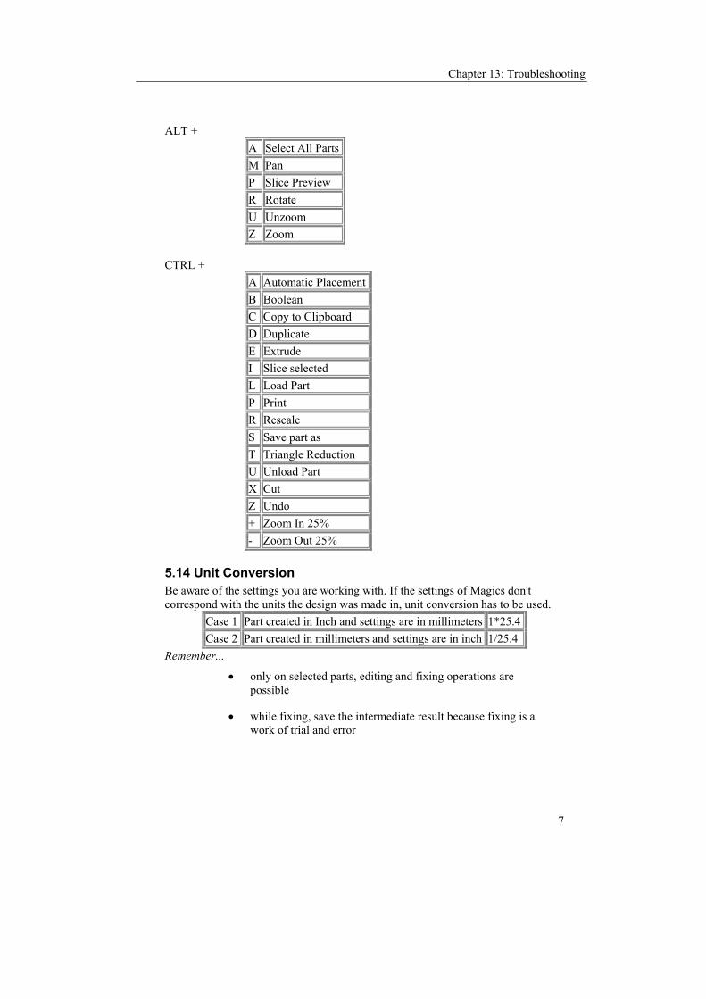
Chapter 13: Troubleshooting
7
ALT + A Select All PartsM Pan P Slice Preview R Rotate U Unzoom Z Zoom
CTRL +
A Automatic PlacementB Boolean C Copy to Clipboard D Duplicate E Extrude I Slice selected L Load Part P Print R Rescale S Save part as T Triangle Reduction U Unload Part X Cut Z Undo + Zoom In 25% - Zoom Out 25%
5.14 Unit Conversion Be aware of the settings you are working with. If the settings of Magics don't correspond with the units the design was made in, unit conversion has to be used.
Case 1 Part created in Inch and settings are in millimeters 1*25.4 Case 2 Part created in millimeters and settings are in inch 1/25.4
Remember...
• only on selected parts, editing and fixing operations are possible
• while fixing, save the intermediate result because fixing is a work of trial and error