5th report sheet metal working metal forming ahmedawad
DESCRIPTION
Manufacturing Process – Metal FormingTRANSCRIPT

Sheet Metal Forming
Sheet metal forming processes are those in which force is applied to a piece of sheet metal to modify its geometry rather than remove any material. The applied force stresses the metal beyond its yield strength, causing the material to plastically deform, but not to fail. By doing so, the sheet can be bent or stretched into a variety of complex shapes. Friction conditions at the tool-metal interface are very important and controlled by press conditions, lubrication, tool material and surface condition, and strip surface condition.
The commercial importance of sheet metalworking is significant. Consider the number of consumer and industrial products that include sheet or plate metal parts: automobile and truck bodies, airplanes, railway cars, locomotives, farm and construction equipment, appliances, office furniture, and more. Sheet-metal parts are generally characterized by high strength, good dimensional accuracy, good surface finish, and relatively low cost. For
components that must be made in large quantities, economical mass-production operations can be designed to process the sheet metal.
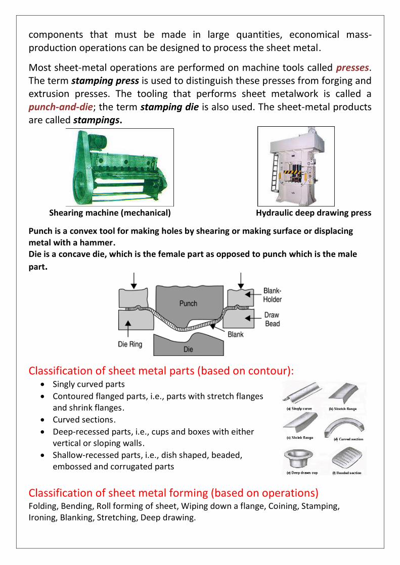
Most sheet-metal operations are performed on machine tools called presses. The term stamping press is used to distinguish these presses from forging and extrusion presses. The tooling that performs sheet metalwork is called a punch-and-die; the term stamping die is also used. The sheet-metal products are called stampings.
Shearing machine (mechanical) Hydraulic deep drawing press
Punch is a convex tool for making holes by shearing or making surface or displacing metal with a hammer. Die is a concave die, which is the female part as opposed to punch which is the male
part.
Classification of sheet metal parts (based on contour): Singly curved parts
Contoured flanged parts, i.e., parts with stretch flanges and shrink flanges.
Curved sections.
Deep-recessed parts, i.e., cups and boxes with either vertical or sloping walls.
Shallow-recessed parts, i.e., dish shaped, beaded, embossed and corrugated parts
Classification of sheet metal forming (based on operations) Folding, Bending, Roll forming of sheet, Wiping down a flange, Coining, Stamping, Ironing, Blanking, Stretching, Deep drawing.
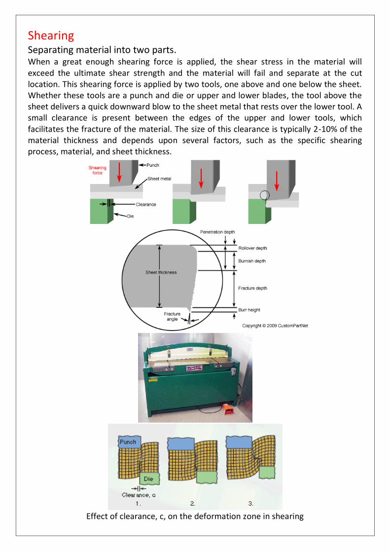
Shearing Separating material into two parts. When a great enough shearing force is applied, the shear stress in the material will exceed the ultimate shear strength and the material will fail and separate at the cut location. This shearing force is applied by two tools, one above and one below the sheet. Whether these tools are a punch and die or upper and lower blades, the tool above the sheet delivers a quick downward blow to the sheet metal that rests over the lower tool. A small clearance is present between the edges of the upper and lower tools, which facilitates the fracture of the material. The size of this clearance is typically 2-10% of the material thickness and depends upon several factors, such as the specific shearing process, material, and sheet thickness.
Effect of clearance, c, on the deformation zone in shearing

Blanking
Removing material to use for parts In this process, the piece removed, called the blank, is not scrap but rather the desired part. Blanking can be used to cutout parts in almost any 2D shape, but is most commonly used to cut workpieces with simple geometries that will be further shaped in subsequent processes. Often times multiple sheets are blanked in a single operation. Final parts that are produced using blanking include gears, jewelry, and watch or clock components. Blanked parts typically require secondary finishing to smooth out burrs along the bottom edge.
Blanking Fine Blanking
Fine blanking is a specialized type of blanking in which the blank is sheared from the sheet stock by applying 3 separate forces. This technique produces a part with better flatness, a smoother edge with minimal burrs, and tolerances as tight as ±0.0003. As a result, high quality parts can be blanked that do not require any secondary operations. However, the additional equipment and tooling does add to the initial cost and makes fine blanking better suited to high volume production. Parts made with fine blanking include automotive parts, electronic components, cutlery, and power tools.

Punching
Removing material as scrap Punching is very similar to blanking except that the removed material, called the slug, is scrap and leaves behind the desired internal feature in the sheet, such as a hole or slot. Punching can be used to produce holes and cutouts of various shapes and sizes. The most common punched holes are simple geometric shapes (circle, square, rectangle, etc.) or combinations thereof. The edges of these punched features will have some burrs from being sheared but are of fairly good quality. Secondary finishing operations are typically performed to attain smoother edges.

A typical punching operation is one in which a cylindrical punch tool pierces the sheet metal, forming a single hole. However, a variety of operations are possible to form different features. These operations include the following: Piercing - The typical punching operation, in which a cylindrical punch pierces a hole into the sheet.
Slotting - A punching operation that forms rectangular holes in the sheet. Sometimes described as piercing despite the different shape.
Perforating - Punching a close arrangement of a large number of holes in a single operation.
Notching - Punching the edge of a sheet, forming a notch in the shape of a portion of the punch.
Nibbling - Punching a series of small overlapping slits or holes along a path to cutout a larger contoured shape. This eliminates the need for a custom punch and die but will require secondary operations to improve the accuracy and finish of the feature.
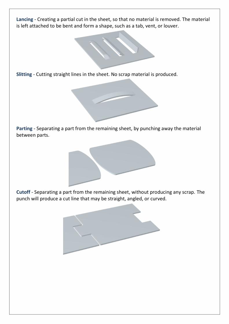
Lancing - Creating a partial cut in the sheet, so that no material is removed. The material is left attached to be bent and form a shape, such as a tab, vent, or louver.
Slitting - Cutting straight lines in the sheet. No scrap material is produced.
Parting - Separating a part from the remaining sheet, by punching away the material between parts.
Cutoff - Separating a part from the remaining sheet, without producing any scrap. The punch will produce a cut line that may be straight, angled, or curved.

Trimming - Punching away excess material from the perimeter of a part, such as trimming the flange from a drawn cup.
Shaving - Shearing away minimal material from the edges of a feature or part, using a small die clearance. Used to improve accuracy or finish. Tolerances of ±0.001 inches are possible.
Dinking - A specialized form of piercing used for punching soft metals. A hollow punch, called a dinking die, with beveled, sharpened edges presses the sheet into a block of wood or soft metal.
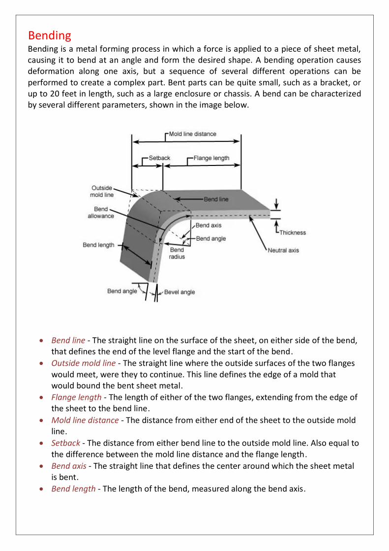
Bending Bending is a metal forming process in which a force is applied to a piece of sheet metal, causing it to bend at an angle and form the desired shape. A bending operation causes deformation along one axis, but a sequence of several different operations can be performed to create a complex part. Bent parts can be quite small, such as a bracket, or up to 20 feet in length, such as a large enclosure or chassis. A bend can be characterized by several different parameters, shown in the image below.
Bend line - The straight line on the surface of the sheet, on either side of the bend, that defines the end of the level flange and the start of the bend.
Outside mold line - The straight line where the outside surfaces of the two flanges would meet, were they to continue. This line defines the edge of a mold that would bound the bent sheet metal.
Flange length - The length of either of the two flanges, extending from the edge of the sheet to the bend line.
Mold line distance - The distance from either end of the sheet to the outside mold line.
Setback - The distance from either bend line to the outside mold line. Also equal to the difference between the mold line distance and the flange length.
Bend axis - The straight line that defines the center around which the sheet metal is bent.
Bend length - The length of the bend, measured along the bend axis.

Bend radius - The distance from the bend axis to the inside surface of the material, between the bend lines. Sometimes specified as the inside bend radius. The outside bend radius is equal to the inside bend radius plus the sheet thickness.
Bend angle - The angle of the bend, measured between the bent flange and its original position, or as the included angle between perpendicular lines drawn from the bend lines.
Bevel angle - The complimentary angle to the bend angle.
Neutral axis - The location in the sheet that is neither stretched nor compressed, and therefore remains at a constant length.
K-factor - The location of the neutral axis in the material, calculated as the ratio of the distance of the neutral axis (measured from the inside bend surface) to the material thickness. The K-factor is dependent upon several factors (material, bending operation, bend angle, etc.) and is typically greater than 0.25, but cannot exceed 0.50.
Bend allowance - The length of the neutral axis between the bend lines, or in other words, the arc length of the bend. The bend allowance added to the flange lengths is equal to the total flat length.
Bend deduction - Also called the bend compensation, the amount a piece of material has been stretched by bending. The value equals the difference between the mold line lengths and the total flat length.
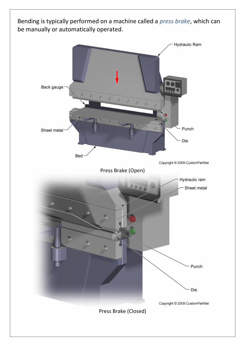
Bending is typically performed on a machine called a press brake, which can be manually or automatically operated.
Press Brake (Open)
Press Brake (Closed)
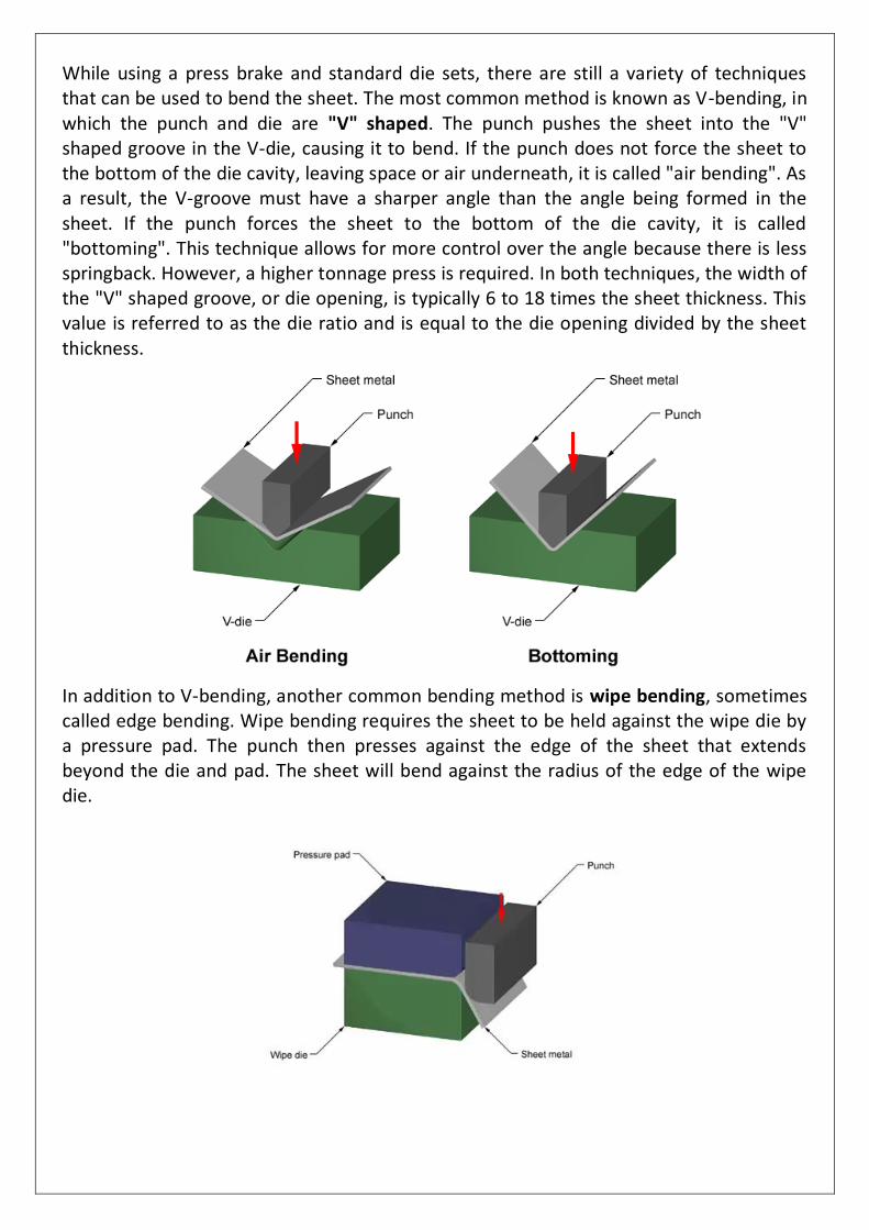
While using a press brake and standard die sets, there are still a variety of techniques that can be used to bend the sheet. The most common method is known as V-bending, in which the punch and die are "V" shaped. The punch pushes the sheet into the "V" shaped groove in the V-die, causing it to bend. If the punch does not force the sheet to the bottom of the die cavity, leaving space or air underneath, it is called "air bending". As a result, the V-groove must have a sharper angle than the angle being formed in the sheet. If the punch forces the sheet to the bottom of the die cavity, it is called "bottoming". This technique allows for more control over the angle because there is less springback. However, a higher tonnage press is required. In both techniques, the width of the "V" shaped groove, or die opening, is typically 6 to 18 times the sheet thickness. This value is referred to as the die ratio and is equal to the die opening divided by the sheet thickness.
In addition to V-bending, another common bending method is wipe bending, sometimes called edge bending. Wipe bending requires the sheet to be held against the wipe die by a pressure pad. The punch then presses against the edge of the sheet that extends beyond the die and pad. The sheet will bend against the radius of the edge of the wipe die.

Roll forming Roll forming, sometimes spelled roll forming, is a metal forming process in which sheet metal is progressively shaped through a series of bending operations. The process is performed on a roll forming line in which the sheet metal stock is fed through a series of roll stations. Each station has a roller, referred to as a roller die, positioned on both sides of the sheet. The shape and size of the roller die may be unique to that station, or several identical roller dies may be used in different positions. The roller dies may be above and below the sheet, along the sides, at an angle, etc. As the sheet is forced through the roller dies in each roll station, it plastically deforms and bends. Each roll station performs one stage in the complete bending of the sheet to form the desired part. The roller dies are lubricated to reduce friction between the die and the sheet, thus reducing the tool wear. Also, lubricant can allow for a higher production rate, which will also depend on the material thickness, number of roll stations, and radius of each bend. The roll forming line can also include other sheet metal fabrication operations before or after the roll forming, such as punching or shearing.
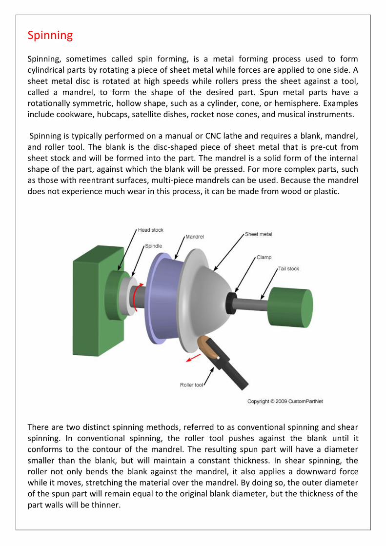
Spinning Spinning, sometimes called spin forming, is a metal forming process used to form cylindrical parts by rotating a piece of sheet metal while forces are applied to one side. A sheet metal disc is rotated at high speeds while rollers press the sheet against a tool, called a mandrel, to form the shape of the desired part. Spun metal parts have a rotationally symmetric, hollow shape, such as a cylinder, cone, or hemisphere. Examples include cookware, hubcaps, satellite dishes, rocket nose cones, and musical instruments.
Spinning is typically performed on a manual or CNC lathe and requires a blank, mandrel, and roller tool. The blank is the disc-shaped piece of sheet metal that is pre-cut from sheet stock and will be formed into the part. The mandrel is a solid form of the internal shape of the part, against which the blank will be pressed. For more complex parts, such as those with reentrant surfaces, multi-piece mandrels can be used. Because the mandrel does not experience much wear in this process, it can be made from wood or plastic.
There are two distinct spinning methods, referred to as conventional spinning and shear spinning. In conventional spinning, the roller tool pushes against the blank until it conforms to the contour of the mandrel. The resulting spun part will have a diameter smaller than the blank, but will maintain a constant thickness. In shear spinning, the roller not only bends the blank against the mandrel, it also applies a downward force while it moves, stretching the material over the mandrel. By doing so, the outer diameter of the spun part will remain equal to the original blank diameter, but the thickness of the part walls will be thinner.
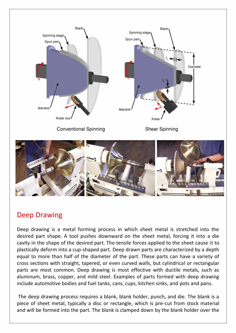
Deep Drawing Deep drawing is a metal forming process in which sheet metal is stretched into the desired part shape. A tool pushes downward on the sheet metal, forcing it into a die cavity in the shape of the desired part. The tensile forces applied to the sheet cause it to plastically deform into a cup-shaped part. Deep drawn parts are characterized by a depth equal to more than half of the diameter of the part. These parts can have a variety of cross sections with straight, tapered, or even curved walls, but cylindrical or rectangular parts are most common. Deep drawing is most effective with ductile metals, such as aluminum, brass, copper, and mild steel. Examples of parts formed with deep drawing include automotive bodies and fuel tanks, cans, cups, kitchen sinks, and pots and pans. The deep drawing process requires a blank, blank holder, punch, and die. The blank is a piece of sheet metal, typically a disc or rectangle, which is pre-cut from stock material and will be formed into the part. The blank is clamped down by the blank holder over the
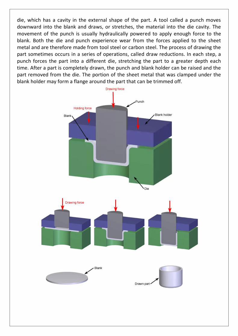
die, which has a cavity in the external shape of the part. A tool called a punch moves downward into the blank and draws, or stretches, the material into the die cavity. The movement of the punch is usually hydraulically powered to apply enough force to the blank. Both the die and punch experience wear from the forces applied to the sheet metal and are therefore made from tool steel or carbon steel. The process of drawing the part sometimes occurs in a series of operations, called draw reductions. In each step, a punch forces the part into a different die, stretching the part to a greater depth each time. After a part is completely drawn, the punch and blank holder can be raised and the part removed from the die. The portion of the sheet metal that was clamped under the blank holder may form a flange around the part that can be trimmed off.
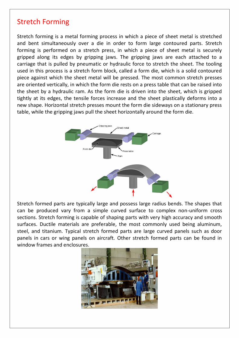
Stretch Forming Stretch forming is a metal forming process in which a piece of sheet metal is stretched and bent simultaneously over a die in order to form large contoured parts. Stretch forming is performed on a stretch press, in which a piece of sheet metal is securely gripped along its edges by gripping jaws. The gripping jaws are each attached to a carriage that is pulled by pneumatic or hydraulic force to stretch the sheet. The tooling used in this process is a stretch form block, called a form die, which is a solid contoured piece against which the sheet metal will be pressed. The most common stretch presses are oriented vertically, in which the form die rests on a press table that can be raised into the sheet by a hydraulic ram. As the form die is driven into the sheet, which is gripped tightly at its edges, the tensile forces increase and the sheet plastically deforms into a new shape. Horizontal stretch presses mount the form die sideways on a stationary press table, while the gripping jaws pull the sheet horizontally around the form die.
Stretch formed parts are typically large and possess large radius bends. The shapes that can be produced vary from a simple curved surface to complex non-uniform cross sections. Stretch forming is capable of shaping parts with very high accuracy and smooth surfaces. Ductile materials are preferable, the most commonly used being aluminum, steel, and titanium. Typical stretch formed parts are large curved panels such as door panels in cars or wing panels on aircraft. Other stretch formed parts can be found in window frames and enclosures.

Ironing Ironing is applied for a defined reduction of the wall thickness of a deep drawn workpiece
Achievement of high wall thickness proportions by multi station ironing Because of the difference in velocity between intake and runout, the workpiece should have left the first ironing die before running into the next
Low distance between ironing dies:
Increase of resulting force in triple drawing
Risk of cup base fracture. Large distance between ironing dies:
Decrease of resulting force in triple drawing,
Large stroke of punch required. High strains can be reached by the use of several ironing steps
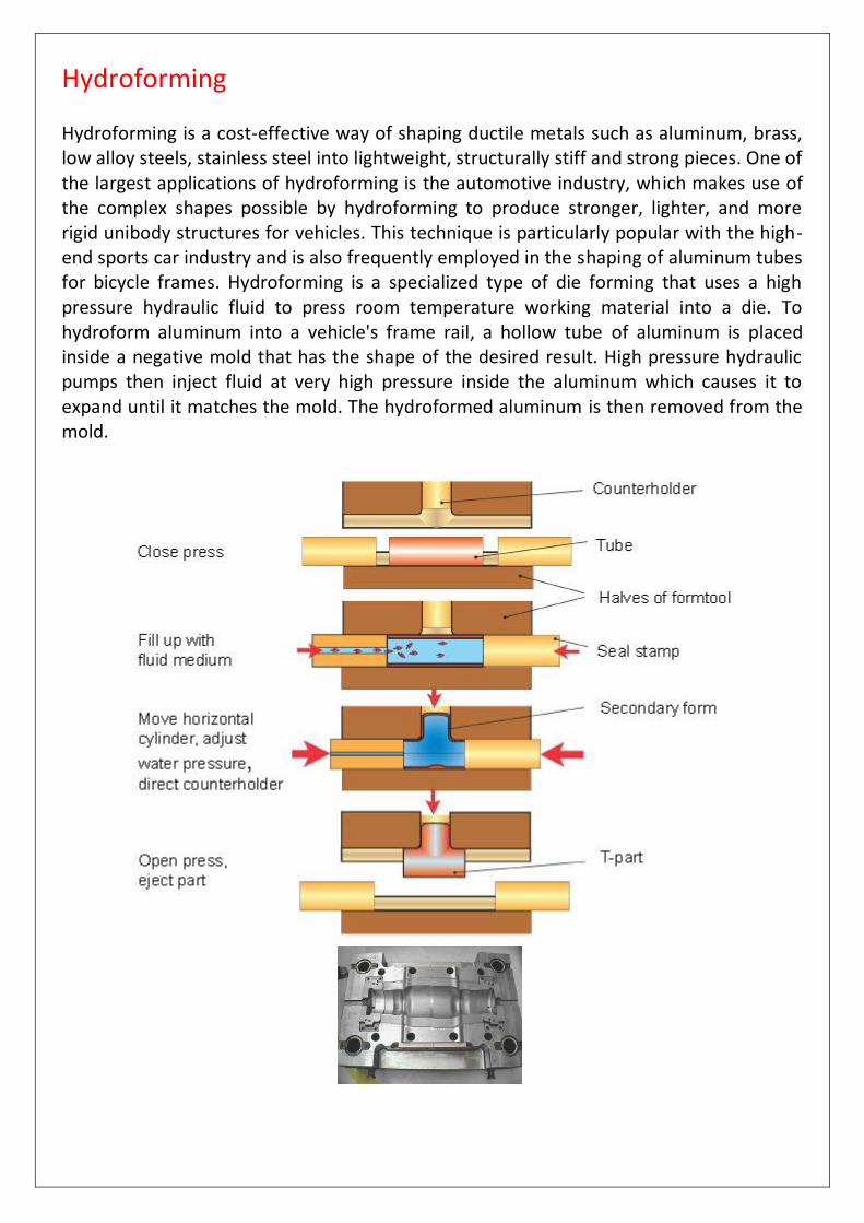
Hydroforming Hydroforming is a cost-effective way of shaping ductile metals such as aluminum, brass, low alloy steels, stainless steel into lightweight, structurally stiff and strong pieces. One of the largest applications of hydroforming is the automotive industry, which makes use of the complex shapes possible by hydroforming to produce stronger, lighter, and more rigid unibody structures for vehicles. This technique is particularly popular with the high-end sports car industry and is also frequently employed in the shaping of aluminum tubes for bicycle frames. Hydroforming is a specialized type of die forming that uses a high pressure hydraulic fluid to press room temperature working material into a die. To hydroform aluminum into a vehicle's frame rail, a hollow tube of aluminum is placed inside a negative mold that has the shape of the desired result. High pressure hydraulic pumps then inject fluid at very high pressure inside the aluminum which causes it to expand until it matches the mold. The hydroformed aluminum is then removed from the mold.