5g over-the-air test implications and solutions
TRANSCRIPT

5G Over-the-Air Test Implications and Solutions
Philip Chang 2019.10.02
Sr. Project Manager/ Keysight Technologies

2
C O M PA S S F O R T H E U N K N O W N
How do we test a
device today, and
what changes
Solutions
EXIT
Device
Development &
Acceptance
Basics
Workflow
Establish Definitions
Outline Challenges

33
5G OTA – What Changed

4
T E S T A N D M E A S U R E M E N T P E R S P E C T I V E
Is my chipset working?
• Chipset verification
• KPI: Signaling, Throughput
Is my RF working?
• RF Verification and Test
• KPI: Output power,
Spurious emission, EVM
How Good is my Antenna?
• Antenna performance OTA tests
• KPI: Antenna Gain, Correlation
Do I have a working device?
• Functional Verification
• KPI: Throughput,
Battery Drain
Over-the-air Cable Connected
5
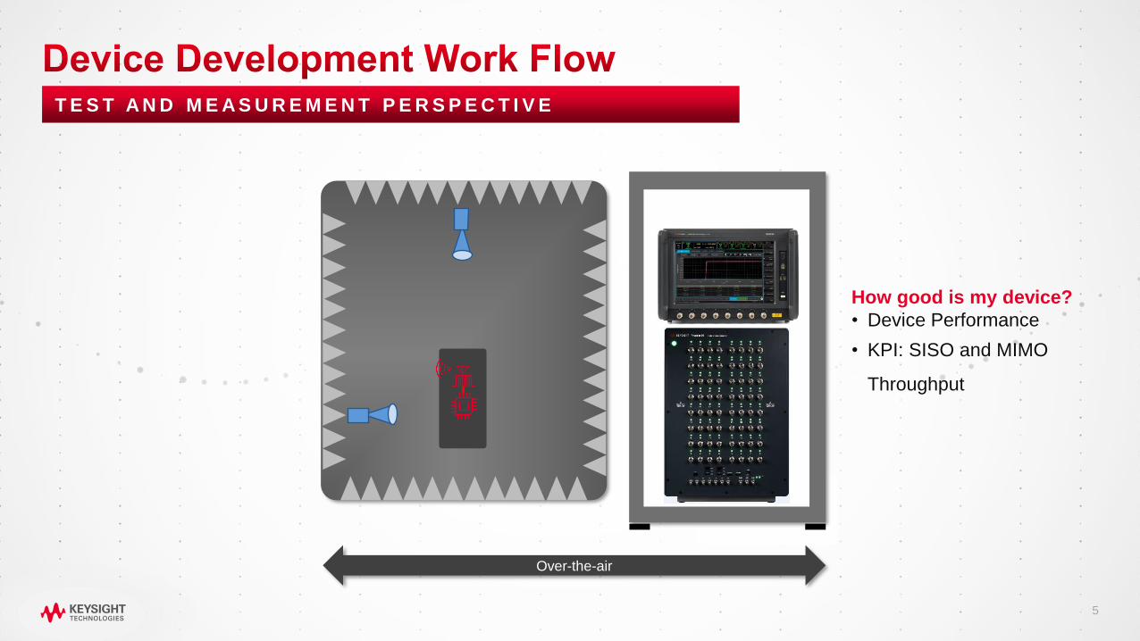
T E S T A N D M E A S U R E M E N T P E R S P E C T I V E
How good is my device?
• Device Performance
• KPI: SISO and MIMO
Throughput
Over-the-air

6
FR1 (Sub-6 GHz) FR2 (mmWave)
<1 GHz 2.5 GHz 3.4 – 3.7 GHz 4.4 – 4.9 GHz ISM 28 GHz 39 GHz
Connector less test for
• Protocol Functionality testing
• Signaling, Full stack, Data
throughput testing
• RF parameters
• Antenna
• Full Device testing
The scope and nature of test has
changed

77
5G mmW Means …..

8
KEEP
CALMBECAUSE
WE ARE GOING
OVER THE AIRWHETHER WE LIKE IT OR NOT!

99
What is OTA?

10
C O M PA S S F O R T H E U N K N O W N
How do we test a
device today, and
what changes
Solutions
EXIT
Device
Development &
Acceptance
Basics
Workflow
Establish Definitions
Outline Challenges

11
L E AV I N G T H E S A F E T Y O F A T R A N S M I S S I O N L I N E
Measurement
Solution
DUT
Plane of
specification
Plane of
calibration
Specified
to here
Calibrated
to here
Predictable
Transmission Line

12
L E AV I N G T H E S A F E T Y O F A T R A N S M I S S I O N L I N E
Measurement
Solution
DUT
Proximate plane of
specification Proximate plane of
calibration
Specified
to here
Calibrated
to here
Infinite possible
transmission Lines
Reject
unwanted
signals
Finite possible
transmission Lines

13
P R I M A R Y C O M P O N E N T S O F A O TA S Y S T E M
Measurement
Solution
RF Test
Capability
Probes
DUT
Positioner
SW
Measurement
& Control
Software
Enclosure = Chamber Quiet/Test
Zone

14
K E Y C O N C E P T: Q U I E T Z O N E V S . T E S T Z O N E
Quiet Zone Test Zone
• Function of chamber design, where RF
Propagation is predictable and well behaved
• Applicable when test accuracy is dependent on
path loss and phase characteristics
• Critical for RF Parametric measurements
• Applied when OTA test is a functional KPI or
protocol test (cable replacement type)
• There are alternate algorithms available to
compensate for any induced variation OR the test
thresholds are set so that the MUs are built into the
tests

15
K E Y C O N C E P T: R A N G E L E N G T H
Enclosure = Chamber
R
Range Length = What should be the distance between the probe and DUT
Range Length
𝑅 =2𝐷2
λ
Decreases when fc increases
Size of the DUT
antenna

16
What is D?
• D can be small as the radiating element or
as large as the entire device
• In handsets, must include coupling to other
radiating elements
• 3GPP has defined 3 device categories
• 3GPP has mandated that the location of the
antennas are not known (black box testing)
• In short – D – can be very large potentially
15 – 30 cms
K E Y C O N C E P T: D E V I C E S I Z E ” D ”
DUT Config 3DUT Config 1 DUT Config 2
No coherence
TR 38.810 Table 5.3-1: DUT Categories
D
D

17
K E Y C O N C E P T: R E A C T I V E N F, N F, A N D F F
• Reactive Near-Field:
• Non-propagating, evanescent fields
predominate.
• Not typically used for measurement
• Radiated Near-Field
• Radiated fields predominate
• But angular distribution is evolving
• Radial field components exist
• Radiated Far-Field
• Angular field distribution stops evolving
• Receiving antenna sees plane-waves
• Only transverse fields
• Obvious location for measurement

18
V E R Y L A R G E C H A M B E R S , W E A K S I G N A L S
D = 5 cm
28 GHz
R = 50 cm
D = 10 cm
28 GHz
R = 190 cm
D = 15 cm
28 GHz
R = 420 cm
-53
dB
-65 dB
-72 dB
Far-field distance at
different frequencies (in m)
D(mm) 28 GHz 39 GHz
50 0.47 0.65
100 1.87 2.60
150 4.20 5.85
200 7.47 10.40
300 16.80 23.40
Path loss: -53 dB to -72 dB
Antenna
Module
Device

19
Much
Bigger
Big
Copyright ©
Verkotan Oy 2019
Bigger
Copyright © Verkotan Oy 2019
20
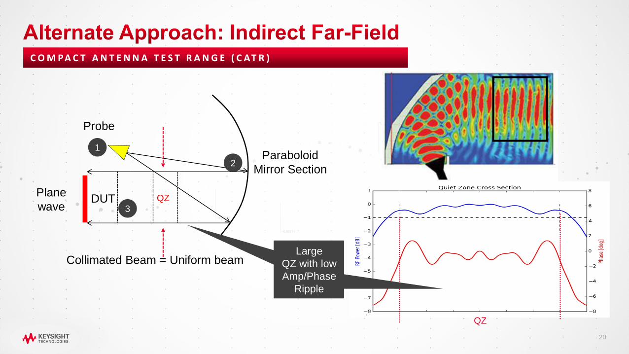
Probe
Plane
wave
Paraboloid
Mirror Section
DUT
Collimated Beam = Uniform beam
1
C O M P A C T A N T E N N A T E S T R A N G E ( C A T R )
2
3QZ
QZ
Large
QZ with low
Amp/Phase
Ripple

21
Indirect Far-Field
• Allows testing of larger mmWave devices with
more compact footprint
• Broadest applicability to 3GPP DUT categories
• Supports testing w/o antenna position declaration
Direct Far-Field
• Simplest design for OTA test
• Devices normally operate in far-field

22
• The IFF test method based on compact
antenna test range (CATR) uses a parabolic
reflector to collimate the signals transmitted by
the probe antenna.
• Creates a far-field test environment in a much
shorter distance and with less path loss than
the DFF method.
• Verizon over-the-air (OTA) testing solution
using Compact Antenna Test Range Chamber
(CATR)
B A S E D O N C AT R / I F F
Example: Indirect Far Field OTA for UE Test
https://www.youtube.com/watch?v=IJOVIHHB9bw
2323
Beyond OTA to Solutions

24
C O M PA S S F O R T H E U N K N O W N
How do we test a
device today, and
what changes
Solutions
EXIT
Device
Development &
Acceptance
Basics
Workflow
Establish Definitions
Outline Challenges

25
A C C E L E R AT I N G I N N O VAT I O N F O R N E W 5 G D E V I C E S
Protocol
Conformance
Carrier
AcceptanceFunctional
KPI
RF/ RRM
ConformanceRF
Automation
Protocol
R&D
5G Interactive
R&D Solutions
5G Device
Acceptance
Solutions
5G MFG
Solutions
Manufacturing
Network
Emulator
mmWave OTA SolutionsChannel Emulator Non-Signaling Test Set

26
E N D - T O - E N D T E S T C O V E R A G E
RF in band, FR1, RRM and Protocol
FR1 (sub-6GHz)
Protocol, RF, RRM
and Functional
Industry leading
GCF and PTCRB test
case support for
5G NR SA and NSA
Add FR2 (mmWave)
and OTA
Add spurious
and interference for RF conformance

27
T E S T A N D M E A S U R E M E N T P E R S P E C T I V E
Cable Connected
Keysight RACK Family
(Cable Replacement/Direct Far-Field)
Chambers
Keysight CATR Family
(Indirect Far-Field) Chambers
OTA Test
Is my chipset working?• Chipset verification
• KPI: Signaling, Throughput
Is my RF working?• RF Verification and Test
• KPI: Output power,
Spurious emission, EVM
Do I have a working
device?• Functional Verification
• KPI: Throughput,
Battery Drain
How good is my antenna?• Antenna performance
• KPI: Antenna Gain,
Correlation

28
VA L I D AT E M M WAV E 5 G D E V I C E S A C R O S S W O R K F L O W
3D MPACCATR
• Indirect far field
• Module to full device testing
• 30 cm device size
RF/Antenna/RCT Protocol/Functional/PCT Mobility and Performance
• Direct far field
• Module to full device testing
• Light weight and bench top
• Direct far field
• Module to full device testing
• Supports fading models with Channel Emulator
2DMPAC RMTC mini-RMTC

29
RF/AntennaProtocol/Functionality
Performance/ IOTManufacturing
gNB MPAC Ultra-Compact Near Field
Functional and Performance Testing With
Bi-Directional Fading
• Protocol Functionality testing
• Integration and Verification of baseband
functionality (CA, Massive MIMO, beam forming)
• NV-IOT functionality
• HETNET functionality
• gNB performance testing
R&D and Early Manufacturing
Volume Manufacturing
• Near field Beam Pattern measurement
• Near field TX Beam parameteric measurement
• Near field Beam RX EIS measurement
• Near field TX Array Calibration
• Near field RX Array Calibration
• OTA RF Parametric Measurements
• Fast measurements for Pass/Fail of DUT
TX Tests
• Output power
• Output power dynamics
• Frequency error
• EVM
• Occupied BW
• ACLR
RX Tests
• Reference sensitivity
• Dynamic Range
• In Band Selectivity & Blocking
• Receiver IM
CATR Compact MPAC

3030
Summary and Conclusions

31
C O M PA S S F O R T H E U N K N O W N
• 4 stages of test: Chipset, RF,
Antenna and Functional test.
• Conducted for FR1
• OTA in FR2 due to lack of
connectors
Solutions
EXIT
• Device development and device
acceptance
• One size fits all approach will not work
• Keysight’s workflow based
solutions pair right OTA
enviroments with right tools
Basics
Workflow
• How a chamber enables OTA
• Larger device sizes and smaller
wavelengths lead to bigger
chambers
• Alterative is to create far-field
indirectly using physics - CATR
