%5b2006%5ddesign of learning input shaping technique for residual vibration suppression in an...
TRANSCRIPT

8/8/2019 %5B2006%5DDesign of Learning Input Shaping Technique for Residual Vibration Suppression in an Industrial Robot
http://slidepdf.com/reader/full/5b20065ddesign-of-learning-input-shaping-technique-for-residual-vibration 1/11
IEEE/ASME TRANSACTIONS ON MECHATRONICS, VOL. 11, NO. 1, FEBRUARY 2006 55
Design of Learning Input Shaping Technique for Residual Vibration Suppression in an Industrial Robot
Juyi Park, Member, IEEE , Pyung-Hun Chang, Member, IEEE , Hyung-Soon Park,and Eunjeong Lee, Member, IEEE
Abstract —In this paper, a practical method is proposed to sup-press residual vibrations of industrial robots without a real-timeestimation of vibration frequencies. Through theoretical analysisand experiments, we designed an input shaping technique (IST)for the rst three axes of a six-degrees-of-freedom industrial robot.Iterative learning IST (LIST) is applied to the rst axis to suppressits time-varying nonlinear residual vibration, while conventionalIST is applied to the second and third axes. Experimental resultsshow that LIST can suppress residual vibrations to a level similarto that of a time-varying IST which requires complicated real-timeestimation of a dynamic model. The LIST is an attractive method
for suppression of nonlinear and time-varying residual vibrationsin industrial robots which perform repetitive tasks because mostindustrial robots have limited computing power and memory spacein their controllers.
Index Terms —Flexible structure, industrial robot, input shap-ing, iterative learning algorithm, residual vibration.
I. INTRODUCTION
I N controlling industrial robots, fast and precise motions arerequired for better productivity. Such motions, however, are
often restricted by residual vibrations in the end-effector, whichtend to be time varying and nonlinear due to the conguration-
dependent friction, inertia variation, and nonlinear stiffness of joints.
For suppression of residual vibrations in exible systems,there are two distinct approaches: open-loop feedforward [1]andclosed-loop feedback [2]. In terms of performance, the latter schemeis more attractive than theformerbecause it is inherentlymore robust against disturbances and parameter variations. Interms of practical implementation, however, the closed-loopapproach makes overall systems more complex and expensive.More specically, the increased states due to vibrational modesincrease theorder of thecontrol systems, thereby requiringmorecomputation andmore sensors as well as themeasurability of the
additional states. Because of thesedifculties, many researchershave developed feedforward schemes integrated with feedbackcontrollers [3], [4]. They reported that the schemes are simple
Manuscript received December 24, 2003; revised April 18, 2005. Recom-mendedby Technical EditorR. V. Patel. Thework of P.-H. Changwas supportedby the Korea Science and Engineering Foundation (KOSEF) through the Center for Human-Friendly Welfare Robotic Systems (HWRS).
J. Park is with Daewoo Shipbuilding and Marine Engineering Company Ltd.,Koje City, 656-714 Korea.
P.-H. Chang and E. Lee are with the Korea Advanced Institute of Science andTechnology (KAIST), Daejon 305-701, Korea.
H.-S. Park is with the Rehabilitation Institute of Chicago, Chicago, IL 60611USA.
Digital Object Identier 10.1109/TMECH.2005.863365
in their structure and robust against disturbances or parameter variations, thus very useful for practical applications.
Based on the observations above, we have considered the in-put shaping technique (IST) proposed by Singer and Seering [3]as the feedforward scheme to be combined with a feedbackcontroller. Since the beginning, the IST has attracted attentionowing to its effectiveness and simplicity. Its effectiveness hasbeen proven in practical systems such as ship cranes [5], chipmounters [6] and open container, of liquid [7]. Nevertheless,since the IST was proposed originally for linear time-invariantsystems [3], it is not so effective for systems with nonlinear and time-varying characteristics such as the multilink robotswe are interested in. Even robust IST [3], which compensatesfor inaccuracies of frequency estimation, is not of much helpfor these systems.
To overcome this difculty, many attempts have been madeto improve IST for nonlinear and time-varying systems. As for nonrobotic systems, onlineadaptiveschemes weredeveloped byTzes and Yurkovich [8] and Bodson [9]. As for robotic systems,Rappole [10] applied a time-varying IST (TVIST) to a two-linkexible manipulator using a lookup table. Magee and Book [11]modied the IST to eliminate the rst two modes of vibration ina large and exible manipulator with a conguration-dependentinertia. Cho and Park [12] proposed a method to determine theexact time-varying impulse sequence andapplied it to a two-linkexible robot. Additionally; there have been similar attempts toapply the IST to various robots [13].
But these schemes require intensive computing power for real-time computation or memory space for a frequency map.Moreover, some schemes require an exact dynamic model of theplant in real time. Because of the limited computing power andmemoryspace of industrial robots, however,it isdifcult to meetthese requirements. Furthermore, it is a major work to obtainan exact model for an industrial robot. These practical issues
have made us develop a scheme to adopt IST for an industrialrobot.The IST we employed in this paper is an iterative learning
IST (LIST) [14], which iteratively updates the parameters of IST based on data from previous trials. The idea central tothis approach came from our observation that most tasks of industrial robots are planned in advance and they are repet-itive by nature. The robot to which we apply iterative LISTis an industrial robot which carries heavy payloads on plantoors.Since IST andLISTwere developed originally for single-input single-output (SISO) systems, this paper deals with tech-niques to extend the application of IST and LIST to industrialrobots that are multiple-input multiple-output (MIMO) systems.
1083-4435/$20.00 © 2006 IEEE
8/8/2019 %5B2006%5DDesign of Learning Input Shaping Technique for Residual Vibration Suppression in an Industrial Robot
http://slidepdf.com/reader/full/5b20065ddesign-of-learning-input-shaping-technique-for-residual-vibration 2/11
56 IEEE/ASME TRANSACTIONS ON MECHATRONICS, VOL. 11, NO. 1, FEBRUARY 2006
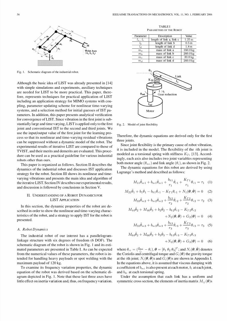
Fig. 1. Schematic diagram of the industrial robot.
Although the basic idea of LIST was already presented in [14]with simple simulations and experiments, auxiliary techniquesare needed for LIST to be more practical. This paper, there-fore, represents techniques for practical application of LISTincluding an application strategy for MIMO systems with cou-pling, parameter updating scheme for nonlinear time-varyingsystems, and a selection method for initial guesses of IST pa-rameters. In addition, this paper presents analytical vericationfor convergence of LIST. Since vibration in the rst joint is sub-stantially large and time varying, LIST is applied only to the rst joint and conventional IST to the second and third joints. Weuse the input/output value of the rst joint for the learning pro-cess so that its nonlinear and time-varying residual vibrationscan be suppressed without a dynamic model of the robot. Theexperimental results of iterative LIST are compared to those of TVIST, and their merits and demerits are evaluated. This proce-dure can be used as a practical guideline for various industrialrobots other than ours.
This paper is organized as follows. Section II describes thedynamics of the industrial robot and discusses IST applicationstrategy for the robot. Section III shows its nonlinear and time-varying vibrations and presents the main idea and algorithm of the iterative LIST. Section IV describesour experimental results,and discussion is followed by conclusions in Section V.
II. UNDERSTANDING OF A ROBOT DYNAMICS FORLIST APPLICATION
In this section, the dynamic properties of the robot are de-scribed in order to show the nonlinear and time-varying charac-teristics of the robot, and a strategy to apply IST for the robot ispresented.
A. Robot Dynamics
The industrial robot of our interest has a parallelogram-linkage structure with six degrees of freedom (6 DOF). Theschematic diagram of the robot is shown in Fig. 1 and its esti-mated parameters are presented in Table I. As can be expectedfrom the numerical values of these parameters, the robot is in-tended for handling heavy payloads or spot welding with themaximum payload of 120 kg.
To examine its frequency variation properties, the dynamicequation of the robot was derived based on the schematic di-agram depicted in Fig. 1. Note that these last three axes have
little effect on inertia variation and, thus, on frequencyvariation.
TABLE IPARAMETERS OF THE ROBOT
Fig. 2. Model of joint exibility.
Therefore, the dynamic equations are derived only for the rstthree joints.
Since joint exibility is the primary cause of robot vibration,it is included in the model. The exibility of the ith joint ismodeled as a torsional spring with stiffness K T i [13]. Accord-ingly, each axis also includes two joint variables representingboth motor angle (θmi ) and link angle (θi ), as shown in Fig. 2.
The dynamic equations for this robot are derived by usingLagrange’s method and described as follows:
M 11 θ̈m 1 + bm 1 θ̇m 1 +bk 1
r 1θ̇r 1 +
K T 1
r 1θr 1 = τ 1 (1)
M 22 θ̈1 + b1 θ̇1 −bk 1 θ̇r 1 −K T 1 θr 1 + N 1 (θ , θ̇ ) = 0 (2)
M 33 θ̈m 2 + bm 2 θ̇m 2 +bk 2
r 2θ̇r 2 +
K T 2
r 2θr 2 = τ 2 (3)
M 44 θ̈2 + M 46 θ̈3 + b2 θ̇2 −bk 2 θ̇r 2 −K T 2 θr 2
+ N 2 (θ , θ̇ ) + G2 (θ ) = 0 (4)
M 55 θ̈m 3 + bm 3 θ̇m 3 +bk 3
r 3 θ̇r 3 +K T 3
r 3 θr 3 = τ 3 (5)
M 64 θ̈2 + M 66 θ̈3 + b3 θ̇3 −bk 3 θ̇r 3 −K T 3 θr 3
+ N 3 (θ , θ̇ ) + G3 (θ ) = 0 (6)
where θr i = ( θm ir i −θi ), θ = [θ1 θ2 θ3 ]T ; and N i (θ , θ̇ ) denotes
the Coriolis and centrifugal torque and Gi (θ ) the gravity torqueat the ith joint; N i (θ , θ̇ )s and G i (θ )s are shown in Appendix I.In the equations above, it is assumed that viscous damping witha coefcient of bm i is also present at each motor, bi at each joint,and bki at each torsional spring.
Under the assumption that each link has a uniform and
symmetric cross section, the elements of inertia matrix M ij (θ )s

8/8/2019 %5B2006%5DDesign of Learning Input Shaping Technique for Residual Vibration Suppression in an Industrial Robot
http://slidepdf.com/reader/full/5b20065ddesign-of-learning-input-shaping-technique-for-residual-vibration 3/11
PARK et al. : INPUT SHAPING TECHNIQUE FOR AN INDUSTRIAL ROBOT 57
can be expressed as the following:
M 11 = J m 1 (7)
M 22 = ( ma lg a2 + J a + J c)c2
2 + ( mblgb2 + J b + J d )c3
2
+ m c(lbc3 −lgcc2 )2 + md (lcc2 + lgdc3 )2
+ mP {
lcc2 + ( l
d −lb)c3
}2 (8)
M 33 = J m 2 (9)
M 44 = m a lga2 + J a + m c lgc
2 + J c + md la2 + mP la
2 (10)
M 46 = {md la lg d −mc lblg c + mP la (ld −lb)}cos(θ2 −θ3 )
(11)
M 64 = M 46 (12)
M 55 = J m 3 (13)
M 66 = mblgb2 + J b + mc lb
2 + md lg d2 + J d + mP (ld −lb)2
(14)where lk and lgk (k = a,b,c,d ), as shown in Fig. 1, denote thelength of the corresponding link and the length to the center of gravity of the link, respectively. In the same manner, mk andJ k represent the mass and moment of inertia of the link, respec-tively. In addition, mP denotes the payload, attached to the end-effector, and ci and s i symbolize cos θi and sin θi , respectively.
Note in (8) and (11) that M 22 and M 46 vary with both θ2 andθ3 , whereas (10) and (14) show that M 44 and M 66 are constant.Owing to M 22 and M 46 , hence, the robot has time-varyingvibrations [15].
The vibration is not only time varying, but also nonlinear due to robot dynamics such as nonlinear spring characteristics
of harmonic drive and friction. Moreover, nonlinear terms indynamic equations, such as Coriolis, centrifugal, and gravitytorque, cause nonlinear residual vibration of the robot. As anexample, let us examine N 1 , which can be expressed in thefollowing form:
N 1 (θ , θ̇ ) = f 1 (θ2 , θ3 , θ̇2 , θ̇3 )θ̇1 . (15)
Since f 1 (θ2 , θ3 , θ̇2 , θ̇3 ) is a nonlinear function, N 1 (θ , θ̇ ) canbe regarded as a nonlinear damper with a nonlinear dampingcoefcient. Therefore, we can see that the nonlinear terms inN 1 cause nonlinear residual vibration of the robot.
Due to such time-varying and nonlinear characteristics, resid-ual vibrations of industrial robots are not well suppressed byconventional IST, which was derived for linear time-invariant(LTI) systems [8]–[10], [12]. To this end, we may apply mod-ied versions of the IST technique for the robot. The authors,however, found that, with properly tuned IST parameters, con-ventional IST can suppress residual vibration in nonlinear andtime-varying systems [14], [16]–[18]. Since conventional ISTdoes not require intensive computational time or large memoryspace, we employed IST to suppress the residual vibration of the industrial robot.
B. IST Application Strategy for the Robot
The dynamic equations above clearly show that the robot is a
multivariable system. Nevertheless, the following observations
are drawn from the analysis of dynamic equations of the robotand experimental verication.
1) For axes 1, 2, and 3, the variation of IST parameters inone axis has little effect on the residual vibration of theother two. For example, even though the IST parametersof axis 1 are changed, the residual vibration in axes 2 and 3
are affected only slightly (Appendix II).2) Residual vibration in axis 1 is dominant while those inaxes 2 and 3 are relatively small (see Fig. 10).
Based on these observations, we have developed a strategy todetermine IST parameters as follows.
1) Apply conventional IST to axes 2 and 3. Although theresidual vibrations in axes 2 and 3 are not eliminatedentirely with conventional IST, the remaining vibrationsarenegligible so that conventional ISTcanbe used in theseaxes without ne tuning.
2) Tune IST parameters for axis 1 by applying iterative learn-ing algorithm.
III. ITERATIVE LEARNING INPUT SHAPING TECHNIQUE
A. IST and Measures of Residual Vibrations
The two-impulse sequence for suppression of the residualvibration is given in the following general form:
u(s) = A1 e−T 1 s + A2 e−T 2 s r (s) (16)
where r (s) is a reference trajectory. The two-impulse sequenceu(s) has four parameters: the magnitudes of impulses A1 andA2 , and the application time T 1 and T 2 . Without loss of general-ity, T 1 may be xed to 0 for a faster response, and A2 may alsobe xed to (1
−A1 ) in order to maintain a unit gain. Then, there
remain only two independent parameters to be determined, A1
and T 2 .According to Singer and Seering’s study [3], the residual
vibrations due to the two-impulse sequence vanish if A1 andT 2 are properly selected by the following equations:
A1 n =1
1 + e−ζ π / √1 −ζ 2(17)
T 2 n =π
ωn 1 −ζ 2(18)
where ( ·)n denotes the exact values of ( ·), and ζ and ωn meanthe damping ratio and the natural frequency of the residualvibration to be suppressed, respectively.
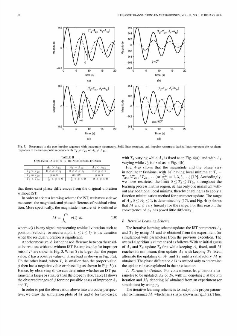
When A1 = A1 n or T 2 = T 2 n , however, the residual vibra-tion does not vanish after the application time T 2 . For exam-ples, we examined the responses for four cases: T 2 > T 2 n andT 2 < T 2 n for A1 = A1 n , and A1 > A 1 n and A1 < A 1 n for T 2 = T 2 n . Fig. 3 shows the responses to the two-impulse se-quence for these four cases. In the gure, the solid lines rep-resent the original vibration, the unit impulse response withoutIST, and the dotted lines represent the resultant responses tothe two-impulse sequence. Fig. 3(a) shows the response for thecase T 2 > T 2 n , and Fig. 3(c) for the case T 2 < T 2 n ; Fig. 3(b)for the case A1 > A 1 n , and Fig. 3(d) for the case A1 < A 1 n .
Both responses show that the residual vibrations still persist and
8/8/2019 %5B2006%5DDesign of Learning Input Shaping Technique for Residual Vibration Suppression in an Industrial Robot
http://slidepdf.com/reader/full/5b20065ddesign-of-learning-input-shaping-technique-for-residual-vibration 4/11
58 IEEE/ASME TRANSACTIONS ON MECHATRONICS, VOL. 11, NO. 1, FEBRUARY 2006
Fig. 3. Responses to the two-impulse sequence with inaccurate parameters. Solid lines represent unit impulse responses; dashed lines represent the resultantresponses to the two-impulse sequence with T 2 = T 2 n or A1 = A1 n .
TABLE IIOBSERVED RANGES OF φ FOR NINE POSSIBLE CASES
that there exist phase differences from the original vibrationwithout IST.
In order to adopt a learning scheme for IST, we have used twomeasures: the magnitude and phase difference of residual vibra-tion. More specically, the magnitude measure M is dened as
M ≡ t f
t i|ν (t)|dt (19)
where ν (t) is any signal representing residual vibration such asposition, velocity, or acceleration. t i
≤t
≤t f is the duration
when the residual vibration is signicant.Another measure, φ, is thephasedifference between theresid-
ual vibrations with andwithout IST. Examples of φ for improper sets of T 2 are shown in Fig. 3. When T 2 is larger than the proper value, φ has a positive value or phase lead as shown in Fig. 3(a).On the other hand, when T 2 is smaller than the proper value,φ then has a negative value or phase lag as shown in Fig. 3(c).Hence, by observing φ, we can determine whether an IST pa-rameter is larger or smaller than the proper value. Table II showsthe observed ranges of φ for nine possible cases of improper A1
and T 2 .In order to put the observation above into a broader perspec-
tive, we draw the simulation plots of M and φ for two cases:
with T 2 varying while A1 is xed as in Fig. 4(a); and with A1
varying while T 2 is xed as in Fig. 4(b).Fig. 4(a) shows that the magnitude and the phase vary
in nonlinear fashions, with M having local minima at T 2 =T 2 n , 3T 2 n , 5T 2 n , . . . (or T 2T 2 n = 1 , 3, 5, . . .) [19]. Accordingly,we have restricted the limit 0 ≤T 2 ≤2T 2 n throughout thelearning process. In this region, M has only one minimum with-out any additional local minima, thereby enabling us to apply afunction minimization method for parameter update. The rangeof A1 , 0 ≤A1 ≤1, is determined by (17), and Fig. 4(b) showsthat M and φ vary linearly for the range. For this reason, theconvergence of A1 has posed little difculty.
B. Iterative Learning Scheme
The iterative learning scheme updates the IST parameters A1
and T 2 by using M and φ obtained from the experiment (or simulation) with parameters from the previous execution. Theoverall algorithmis summarized as follows:Withan initial guessof A1 and T 2 , update T 2 rst while keeping A1 xed, until M reaches its minimum; then update A1 with keeping T 2 xed;alternate the updating of A1 and T 2 until a satisfactory M isobtained. The phase difference φ is examined only to determinethe update rule as explained in the next section.
1) Parameter Update: For convenience, let p denote a pa-rameter to be updated, A1 or T 2 , with pk denoting p at the kthiteration and M k denoting M obtained from an experiment (or simulation) by using pk .
The iterative learning scheme is to nd pn , the proper param-
eter to minimize M , which has a shape shown in Fig. 5(a). Thus,

8/8/2019 %5B2006%5DDesign of Learning Input Shaping Technique for Residual Vibration Suppression in an Industrial Robot
http://slidepdf.com/reader/full/5b20065ddesign-of-learning-input-shaping-technique-for-residual-vibration 5/11
PARK et al. : INPUT SHAPING TECHNIQUE FOR AN INDUSTRIAL ROBOT 59
Fig. 4. Variation of M and φ: (a) for T 2 varying with A1 xed, (b) for A1 varying with T 2 xed.
Fig. 5. The shape of M and M̃ .
updating the IST parameters may be regarded as a function min-imization and various function minimization techniques can beused to this end.
Froma differentperspective,however, theparameterupdatingmay beviewed asa root nding problem andvarious root ndingmethods can be utilized for this purpose. To elaborate, dene a
e˜
M asM̃ = M sign( pn − p) (20)
where
sign(x) =1, if x > 00, if x = 0
−1, if x < 0.
Fig. 5(b) shows M̃ as a function of p. Note that the condition,sign(x) = 0 if x = 0 , makes M̃ = 0 when p = pn , and thus wecan use root nding methods for parameter updates.
In parameter updating, we have made use of a well estab-lished function minimization method called the golden sectionsearch [20] in conjunction with a root nding method called thesecant method [21]. The latter was used to increase the speed of convergence for the former.
Brieysummarizing, thegoldensection search isbased on thefact thata minimum can befound when there is a triplet ofpoints,a < b < c , such that f (b) is less than both f (a) and f (c). In thiscase, the function has a minimum in the interval [a, c]. With thisidea, one can narrow down the interval by choosing a new pointd between a and b or between b and c. Let us suppose that d ischosen between b and c. Then we know that a minimum is inthe interval [b, c] if f (d) < f (b) as in Fig. 6(a); or a minimumis in the interval [a, d ] if f (b) < f (d) as shown in Fig. 6(b). As
the process above is repeated with a new triplet b < d < c or
Fig.6. (a) A minimum isin the interval [b, c] if f (d) < f (b) or (b)a minimumis in the interval [a, d ] if f (b) < f (d) .
Fig. 7. If M̃ is discontinuous near pn , pk +1 obtained by (21) may be too far from pn .
a < b < d , the interval in which f (x) has a minimum can benarrowed down.
In thegolden section search, thenew point d in a given intervalis called the golden mean point since it is normally selected asa golden mean of the given triplet [21]. Instead of using thegolden mean point method, however, the secant method is usedto increase the speed of convergence. This is possible becausewe know the sign of ek from φ, where ek = pn − pk .
In the secant method, pk +1 is calculated from
pk +1 = pk + ( pk − pk−1 )M̃ k
M̃ k−1 −M̃ k(21)
where M̃ j is the M̃ obtained from experiment or simulationusing p j .
The secant method, however, does not work well when M̃ isnot continuousnear pn asshown inFig.7, because it assumes thefunction to be smooth near the root [21]. If M̃ is discontinuous
near pn , (21) determines pk +1 far from pn as shown in Fig. 7.

8/8/2019 %5B2006%5DDesign of Learning Input Shaping Technique for Residual Vibration Suppression in an Industrial Robot
http://slidepdf.com/reader/full/5b20065ddesign-of-learning-input-shaping-technique-for-residual-vibration 6/11
60 IEEE/ASME TRANSACTIONS ON MECHATRONICS, VOL. 11, NO. 1, FEBRUARY 2006
Fig. 8. pk +1 isnot inthe interval where M hasa minimumwhen theparameter is updated improperly.
As a remedy to overcome this difculty, the following con-straint is added:
| pk +1 − pk | ≤ | pk − pk−1 |. (22)
As a result, when M̃ is discontinuous near pn , the followingequation is used instead of (21):
pk +1 = pk + ( pk − pk−1 )satM̃
kM̃ k−1 −M̃ k (23)
where sat( x) is a saturation function such that
sat(x) = x, if |x| < 1sign(x), otherwise .
We have proved that the updating scheme described thus far makes pk converge to pn as iteration proceeds. The proof ispresented in Appendix III.
2) Updating Rule for Varying Frequencies: For some non-linear systems, the phase difference φ is not reliable any more.For example, a spring-mass system with a nonlinear spring vi-brates with decreasing frequencies as the amplitude becomessmaller, and it is of no use to measure φ between vibrations thathave different frequencies.
In the case of nonlinear systems with vibrations of varyingfrequencies, therefore, we use a simple trial-error methodsuch as the following instead of using φ for parameter update:Assume that both pk and pk−1 are either larger or smaller than pn , that is, ek ek−1 > 0. Let us apply this assumption to (23)and obtain the following equation to calculate pk +1 :
pk +1 = pk + ( pk − pk−1 )
×satM k sign(ek )
M k−1 sign(ek−1 ) −M k sign(ek )
= pk + ( pk − pk−1 )satM k
M k−1 −M k. (24)
If pk +1 obtained from (24) is in the interval in which M has aminimum, 1 our assumption is conrmed to be correct, and thelearning proceeds to the next cycle. On the contrary, if the pk +1
is not in the interval in which M has a minimum (as shown inFig. 8), it indicates that the pk +1 was not properly updated, thatis, the assumption is wrong. Hence, applying ek ek−1 < 0 to
1It was explained with the golden section search.
Fig. 9. Experimental setups used for the LIST. The learning process is doneon the IBM-PC 486.
(23), we can obtain the following equation to calculate pk +1 :
pk +1 = pk −( pk − pk−1 )satM k
M k−1 + M k. (25)
Although this method increases the iteration numbers anddelays the convergence of M , it enables us to obtain exact pk +1
without φ. 3) Selection of Initial Parameters: The initial guesses of A1
and T 2 can be calculated using Singer’s method [3]. Althoughthis method is derived from and intended for LTI systems, wend that they still provide good initial guesses for nonlinear time-varying systems.
At the second iteration, p1 cannot be obtained by using theupdating rule mentioned above because it requires two previousexperimental results. The new updating rule for p1 is made inthe following form:
p1 = p0 −sign(e0 ) p0 δ (26)
where δ denotes a heuristically determined constant less thanone. In our learning process, we use δ = 0 .1 and sign (e0 ) isobtained from the initial phase difference φ0 .
4) Condition for Minimum M : As mentioned above, we cannarrow down the interval where M hasa minimum—or M̃ has aroot—through the learning process. We can say that M has con-verged to its minimum if the interval is sufciently small so that
pU − pL < (27)
where pU and pL denote the upper and lower bound of theinterval, respectively and the predened error bound.
IV. EXPERIMENT
A. Experimental Setup
Experiments were performed to verify that iterative LISTis effective for suppression of residual vibrations in a robotconducting repetitive tasks. For the experiments, the referencetrajectory with its trapezoidal velocity prole was given, andthe results of iterative LIST were then compared to those of both conventional IST as well as TVIST based on Rappole’smethod [10], [15].
The schematic diagram of the experimental setup is shownin Fig. 9. As position controllers, proportional controllers withinner PI velocity control loops run in a stand-alone robot con-
troller at sampling frequency 2 kHz. An accelerometer, from

8/8/2019 %5B2006%5DDesign of Learning Input Shaping Technique for Residual Vibration Suppression in an Industrial Robot
http://slidepdf.com/reader/full/5b20065ddesign-of-learning-input-shaping-technique-for-residual-vibration 7/11
PARK et al. : INPUT SHAPING TECHNIQUE FOR AN INDUSTRIAL ROBOT 61
Fig. 10. Experimental results: residual vibration without IST. Note that therobot moved for 1.35 s and the tip response after 1.35 s is the residual vibration.
PCB Piezotronics, Inc., is attached at the tip of the robot tomeasure the residual vibrations of the tip.
As shown in Fig. 9, IST is implemented on the robot con-troller, whereas the learning algorithm is carried out in theoutside controller, an IBM PC 486DX2-66. While the robotis moving, the acceleration signals sensed by the accelerom-
eter are sent to the PC. Then the signals are read by an A/Dconverter at sampling frequency 200 Hz and ltered througha bandpass lter to lter out both drift signals and noise. Theltered acceleration signals are stored in the PC memory. After one cycle of motion, the PC calculates M and φ, and up-dates the IST parameters. The values of the updated IST pa-rameters are sent to the robot controller, and the next cyclebegins.
Prior to the application of IST lters for the robot, we ex-amined the level of the residual vibrations without IST lters.In these experiments, the reference trajectories were given asS-curves with trapezoidal velocity proles. Fig. 10 shows thetip acceleration signal processed through a lter with a band-width between 2–30 Hz, when only feedback control is used.The robot traveled for 1.35 s and the tip response after 1.35 s isregarded as the residual vibration. As is shown in the gure, theresidual vibrations in the swing direction, which were causedby the axis 1’s movement, are substantially larger than those inother directions.
The experiment above made us observe that the frequency of residual vibration decreaseswith smaller amplitude whereas thedamping ratio remains nearly constant.The frequency variation,in our study, is caused by both the time-varying inertia due tochange of the robot’s conguration and the nonlinear exibilityin the harmonic drive.
Inorder to demonstrate theeffectiveness of iterative LIST, twoother schemesof IST havebeen compared:conventional ISTandthe TVIST based on Rappole’s method [10], [15], respectively.They are described as follows.
1) If Foradoptingconventional ISTtononlineartime-varyingsystems, we have designed an IST lter using the meanvalue of varying frequencies.
2) If The TVIST is represented by
u(t) = A1 r (t) + A2 r (t −T 2 (t)) . (28)
The second impulse varies with time, and its applicationtime T 2 (t) is estimated in real time from the position data
of each axis.
Fig.11. Experimental results. Magnitude measure M decreases as the number of iterations increases.
Fig. 12. Tip acceleration measured in swing direction (axis 1). Both TVISTand LIST have suppressed the residual vibrations. Note that because the robotmoved for 1.35 s, the tip acceleration after 1.35 s is the residual vibration.
B. Experimental Results
Fig. 11 shows the experimental results of the proposed iter-ative LIST. With the initial parameters, the magnitude of theresidual vibration is quite large. As the number of iterations in-creases, the residual vibrations become smaller and M reachesits minimum at the sixth iteration. Note that tip acceleration isused as ν (t) to calculate M using (19).
In Fig. 12, the results of iterative LIST are compared withthose of TVIST. LIST and TVIST reduced the peak residualvibration to 14% and 13% of the original vibration without IST,respectively, whereas IST reduced it only to 40%. Therefore,the comparison displays that both iterative LIST and TVISThave well suppressed the residual vibrations, which implies thatwe can choose any of the two schemes according to applicationconditions. If the real-time estimation of the varying frequencyis both possible and affordable, TVIST is applicable; if not, and
the task is repetitive, iterative LIST is suitable.Although higher frequency vibrations exist in the transient
region, their amplitudes are very small. In our application, suchvibrations in the transient region were not important becausethis robot was designed for point-to-point motion. Therefore,we believe that LIST is useful for the repetitive tasks whichconsist of point-to-point motions.
V. CONCLUSION
For suppression of nonlinear and time-varying residualvibrations in a 6-DOF industrial robot, we have proposed aniterative LIST which updates the parameters of IST by using
data from previous trials. Based on theoretical analysis and
8/8/2019 %5B2006%5DDesign of Learning Input Shaping Technique for Residual Vibration Suppression in an Industrial Robot
http://slidepdf.com/reader/full/5b20065ddesign-of-learning-input-shaping-technique-for-residual-vibration 8/11

8/8/2019 %5B2006%5DDesign of Learning Input Shaping Technique for Residual Vibration Suppression in an Industrial Robot
http://slidepdf.com/reader/full/5b20065ddesign-of-learning-input-shaping-technique-for-residual-vibration 9/11
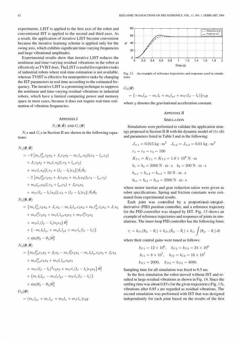
PARK et al. : INPUT SHAPING TECHNIQUE FOR AN INDUSTRIAL ROBOT 63
Fig. 14. Residual vibrations with various IST parameters of axis 1: θi −θm iafter settling time (a) without IST, (b) with IST, and (c) with IST parameter variation in axis 1. Note that dashed and thick solid lines overlap each other inaxes 2 and 3.
TABLE IIITRAJECTORIES AND SIMULATIONS RESULTS
simulation. As shown in Fig. 14, residual vibrations in axes 2and3 were reduced to 17.6% and18.2%of theoriginalvibration,respectively. The next simulation was to examine the variationof residual vibrations in axes 2 and 3 with a change of ISTparameters in axis 1. IST parameters in axis 1, therefore, weredecreased by 50% while keeping those in axes 2 and 3 constant.Comparing the results with those of the second simulation, weobserved that there were very little differences.
More simulations were performed with various trajectories aslisted in Table III. The values summarized in the table represent
the maximum peak-to-peak amplitude of residual vibrations
Fig. 15. Three different cases in updating parameters.
compared with those of residual vibrations without IST. Thesimulation results exhibit that the peak amplitude of residualvibrations in axes 2 and 3 varied only by 1% to 3%, while theIST parameter in axis 1 had a negligible effect on the residualvibration of the other two axes.
APPENDIX III
CONVERGENCE OF LIST
For the purpose of verifying the convergence of the proposedupdating rule, theerror ( p− pn ) is examined. First, theupdatingcondition is divided into the following two cases for examina-tion.
Case 1) Both pk−1 and pk are smaller or larger than pn asshown in Fig. 15(a).
Case 2) Either pk−1 or pk is smaller than pn and the other islarger than pn as shown in Fig. 15(b).
Without loss of generality, we considered a situation repre-sented in Fig. 15(a) for Case 1. By subtracting pn from bothsides of (23), we obtain
ek +1 = ek + ( pk − pk−1 )sat˜
M kM̃ k−1 −M̃ k(29)
where e j = p j − pn . Since pk−1 < p k < p n and M̃ k < M̃ k−1 ,we know that
ek < 0, pk − pk−1 > 0, M̃ k−1 −M̃ k > 0.
With these inequalities, (29) can be
ek +1 = −|ek |+ ( pk − pk−1 )satM̃ k
M̃ k−1 −M̃ k. (30)
If pk +1 < p n as shown in Fig. 15(a-1), the following inequal-
ity is obtained from (30):
|ek +1 | = |ek | −( pk − pk−1 )satM̃ k
M̃ k−1 −M̃ k< |ek |.
(31)On the other hand, if pk +1 > p n as shown in Fig. 15(a-2), thefollowing inequality holds from (30):
|ek +1 | = −|ek |+ ( pk − pk−1 )satM̃ k
M̃ k−1 −M̃ k
≤ −|ek |+ ( pk − pk−1 ) = −2|ek |+ |ek−1 |< |ek−1 |. (32)

8/8/2019 %5B2006%5DDesign of Learning Input Shaping Technique for Residual Vibration Suppression in an Industrial Robot
http://slidepdf.com/reader/full/5b20065ddesign-of-learning-input-shaping-technique-for-residual-vibration 10/11
64 IEEE/ASME TRANSACTIONS ON MECHATRONICS, VOL. 11, NO. 1, FEBRUARY 2006
Equations (31) and (32) can be combined as follows:
|ek +1 | < max[|ek |, |ek−1 |]. (33)
Moreover, (33) can be represented as (34) by introducing aconstant ck +1 which satises 0 < c k +1 < 1:
|ek +1 | < c k +1 max[|ek |, |ek−1 |]. (34)
In Case 2, we obtain the following equation from (21):
ek +1 =M̃ k−1 ek −M̃ k ek−1
M̃ k−1 −M̃ k. (35)
Since ek ek−1 < 0 and M̃ k M̃ k−1 < 0 as shown in Fig. 15(b),(35) becomes
|ek +1 | =M̃ k−1 ek | − |M̃ k ek−1
|M̃ k−1 |+ |M̃ k |≤
M̃ k−1 | − |M̃ k
|M̃ k−1 |+ |M̃ k |max( |ek |, |ek−1 |)
< c k +1 max( |ek |, |ek−1 |) (36)
where ck +1 is a constant whichsatises (max ( |M̃ k−1 |, |M̃ k |)) /(|M̃ k−1 |+ |M̃ k |) < c k +1 < 1.
From (34) and (36), we can say that |ek +1 | has the followinginequality:
|ek +1 | < c M max( |ek |, |ek−1 |) (37)
where cM is a maximum value among all c j s for j =
2, 3, . . . , ∞. By using (37), |e j | for j = 2 , 3, 4, . . . , k is rep-resented as follows:
|e2 | < c M eM
|e3 | < c M max( |e1 |, |e2 |) < c M eM
...
|ek | < c k−2M eM
where eM = max( |e0 |, |e1 |). As a result,
limk→∞|ek | < lim
k→∞ck−2
M eM = 0 . (38)
In other words, pk converges to pn as iteration proceeds.
REFERENCES
[1] H. Asada,Z.-D.Ma, andH. Tokumaru,“Inverse dynamicsof exible robotarms of trajectory control,” in Proc. Modeling and Control of Robotic Manipulators, 1987 ASME Winter Annu. Meeting , 1987, pp. 329–336.
[2] P. T. Kotnik, S. Yurkovich, and U. Ozguner, “Acceleration feedback for control of a exible manipulator arm,” J. Robot. Syst. , vol. 5, no. 3,pp. 181–196, Jun. 1988.
[3] N. C. Singer and W. P. Seering, “Preshaping command inputs to reducesystem vibration,” Trans. ASME, J. Dyn. Syst. Meas. Control , vol. 112,pp. 76–82, 1990.
[4] M. Ballesteros and W. Book, “Implementation alternatives for dual ratecontrol systemswith commandshaping,” in Proc.American Control Conf. ,2002, pp. 2285–2291.
[5] M. Agostini, G. G. Parker, K. Groom, H. Schaub, and R. D. Robinett,“Command shaping and closed-loop control interactions for a shipcrane(I),” in Proc. 2002 American Control Conf. , 2002, pp. 2298–2304.
[6] P. H. Chang and J. Park, “A concurrent design of input shaping tech-nique and a robust control for high-speed/high-precision control of a chipmounter,” Control Eng. Practice , vol. 9, no. 12, pp. 1279–1285, Dec.2001.
[7] J. T. Feddema et al. , “Control for slosh-free motion of an open container,” IEEE Control Syst. Mag. , vol. 17, no. 1, pp. 29–36, Feb. 1997.
[8] A. Tzes and S. Yurkovich, “An adaptive input shaping control scheme for vibration suppression in slewing exible structures,” IEEE Trans. Contr.Syst. Technol. , vol. 1, no. 2, pp. 114–121, Jun. 1993.
[9] M. Bodson, “An adaptive algorithm for the tuning of two input shapingmethods,” in Proc. American Control Conf. , vol. 3, 1997, pp. 1340–1344.
[10] B. W. Rappole,“Minimizing residualvibrations in exiblesystems,” Mas-ter’s thesis, Dept. Mech. Eng., MIT, Cambridge, MA, 1992.
[11] D. P. Magee and W. J. Book, “Implementing modied command lteringto eliminatemultiple modes of vibration,” in Proc. 1993 American ControlConf. , Jun. 1993, pp. 2700–2704.
[12] J. K. Cho and Y. Park, “Vibration reduction in exible systems using atime-varying impulse sequence,” Robotica , vol. 13, pp. 305–313, 1995.
[13] R. Kinceler and P. H. Meckl, “Corrective input shaping for a exible-jointmanipulator performing point-to-point motion,” in Proc. IEEE Int. Conf.Control Applications , 1996, pp. 391–396.
[14] J. Park and P. H. Chang, “Learning input shaping technique for non-LTI
systems,” Trans. ASME, J. Dyn. Syst. Meas. Control , vol. 123, pp. 288– 293, Jun. 2001.
[15] H. S. Park, P. H. Chang, and J. S. Hur, “Time-varying input shapingtechnique for an industrial robot,” in Proc. IEEE/RSJ Int. Conf. Intelligent Robots and Systems , vol. 1, 1999, pp. 285–290.
[16] J. Y. Smith, K. Kozak, and W. E. Singhose, “Input shaping for a simplenonlinear system,” in Proc. American Control Conf. , 2002, pp. 821–826.
[17] J. Park, P. H. Chang, and E. Lee, “Can a time invariant input shapingtechnique eliminate residual vibrations of LTV systems?,” in Proc. 2002 American Control Conf. , 2002, pp. 2292–2297.
[18] J. Park and C. B. Schrader, “Can an input shaper with two impulsessuppress nonlinear residual vibrations?,” in Proc. 2003 American ControlConf. , 2003, pp. 3172–3177.
[19] T. Singh and S. R. Vadali, “Robust time-delay control,” Trans. ASME, J. Dyn. Syst. Meas. Control , vol. 115, no. 2, pp. 303–306, 1993.
[20] W. H. Press, B. P. Flannery, S. A. Teukolsky, and W. T. Vetterling, Numer-ical Recipes in C, The Art of Scientic Computing. Cambridge, U.K.:Cambridge Univ. Press, 1988.
[21] L. W. Johnson and R. D. Riess, Numerical Analysis , 2nd ed. Reading,MA: Addison-Wesley, 1982.
Juyi Park (M’02) received the B.S. degree in pro-duction engineering the M.S. degree in precision en-gineering, and the Ph.D. degree in mechanical engi-neering fromthe Korea AdvancedInstitute of Scienceand Technology (KAIST), Daejon, Korea, in 1991,1993, and 2001, respectively.
He was a Postdoctoral Fellow at the Universityof Texas at San Antonio from 2001 to 2002. From2002 to 2004, he was a Research Associate in theDepartment of Electrical Engineering and Computer Science, VanderbiltUniversity, Nashville, TN. Since,
2004, he has been working on intelligent robot controllers at the Robot R&DInstitute, Daewoo Shipbuilding and Marine Engineering Company Ltd., KojeCity, Korea. His research interests are suppression of residual vibration in ex-ible structures, robots for disabled people, and real-time robot controllers.
Pyung-Hun Chang (S’86–M’89) was bornin Pusan,Korea, in 1951. He received the B.S. and M.S. de-grees from Seoul National University (SNU), Seoul,Korea, in 1974 and 1977, respectively, and the Ph.D.degree from the Massachusetts Institute of Technol-ogy (MIT), Cambridge, MA, in 1987, all in mechan-ical engineering.
From 1984 to 1987, he was involved in a researchproject in the eld of robotics as a Research Assis-tant at the Articial Intelligence Laboratory of MIT.Since 1987, hehas beenon the faculty ofand isnowa

8/8/2019 %5B2006%5DDesign of Learning Input Shaping Technique for Residual Vibration Suppression in an Industrial Robot
http://slidepdf.com/reader/full/5b20065ddesign-of-learning-input-shaping-technique-for-residual-vibration 11/11
PARK et al. : INPUT SHAPING TECHNIQUE FOR AN INDUSTRIAL ROBOT 65
Professor in the Department of Mechanical Engineering, Korea Advanced Insti-tute of Science and Technology (KAIST), Daejon, Korea. His research interestsare high accuracy/speed control with application to mechanical systems, robustcontrol of nonlinear plants such as robot manipulators, and task-oriented designof robot manipulators.
Hyung-Soon Park was born in Seoul, Korea, in1972. He received the B.S. degree in precision en-gineering and the M.S. and Ph.D. degrees in mechan-ical engineering from the Korea Advanced Instituteof Science and Technology (KAIST), Daejon, Korea,in 1994, 1996, and 2004, respectively.
He is currently a Research Associate at the Re-habilitation Institute of Chicago, Chicago, IL. Hisresearch interests include robust control algorithms,design and control of rehabilitation robots, and tele-operation systems.
Eunjeong Lee (S’88–M’94) received the B.S. de-gree from Ajou University, Suwon, Korea, in 1986,the M.S. degree from Northwestern University,Evanston, IL, in 1989, and the Ph.D. degree fromCase Western Reserve University, Cleveland, OH, in1994, all in mechanical engineering.
Sheis currentlya Visiting Professorin theDepart-ment of Electrical Engineering and Computer Sci-ence at the Korea Advanced Institute of Science andTechnology (KAIST), Daejon, Korea. She was anAssistant Professor in the Department of Mechanical
Engineering at the University of Texas at San Antonio from 2000 to 2002. Her research interests are biomimetics at the micro/nanoscale, MEMS, intelligentcontrol, and superconducting renewable evergy systems.
Dr. Lee received a University of Houston/NASA Johnson Space Cen-ter Aerospace Postdoctoral Fellowship (1996–1999) and the Workshop Ma-terial/Product Performance Award from the 1997 International Workshop onSuperconductivity. She served the IEEE Control Stytems Society as an Asso-ciate Editor for the Conference Editorial Board from 2000 to 2002. She is alsoa member of ASME.