document
TRANSCRIPT

NATURE | VOL 411 | 7 JUNE 2001 | www.nature.com 657
articles
Potassium channel receptor site for theinactivation gate and quaternary amineinhibitorsMing Zhou, JoaÄo H. Morais-Cabral*, Sabine Mann & Roderick MacKinnon
Howard Hughes Medical Institute, Laboratory of Molecular Neurobiology and Biophysics, Rockefeller University, 1230 York Avenue, New York, New York 10021, USA
............................................................................................................................................................................................................................................................................
Many voltage-dependent K+ channels open when the membrane is depolarized and then rapidly close by a process calledinactivation. Neurons use inactivating K+ channels to modulate their ®ring frequency. In Shaker-type K+ channels, the inactivationgate, which is responsible for the closing of the channel, is formed by the channel's cytoplasmic amino terminus. Here we showthat the central cavity and inner pore of the K+ channel form the receptor site for both the inactivation gate and small-moleculeinhibitors. We propose that inactivation occurs by a sequential reaction in which the gate binds initially to the cytoplasmic channelsurface and then enters the pore as an extended peptide. This mechanism accounts for the functional properties of K+ channelinactivation and indicates that the cavity may be the site of action for certain drugs that alter cation channel function.
The presence of an inactivation gate causes a K+ channel to closespontaneously after opening induced by membrane depolariza-tion (Fig. 1a). The inactivation gate in Shaker-type K+ channelsis formed by the ®rst 20 amino acids on the N terminus of thea-subunit1,2 or b-subunit3, located on the intracellular side of themembrane (Fig. 1c, d). The essential chemical characteristics thatenable the N terminus to act as a gate are that the ®rst approximately10 amino acids tend to be hydrophobic (hydrophobic region) andthe remaining 10 hydrophilic with excess positive charge (hydro-philic region)4,5 (Fig. 1d).
Four lines of evidence support the idea that the inactivation gatebinds to the pore. First, inactivation occurs only after the voltage-dependent gate opens, as if the opening of the pore exposes areceptor for the gate6. Second, inactivation is produced by thebinding of only one gate, presumably to the single pore opening,even though K+ channels have four gates (N termini), by virtue oftheir homotetrameric architecture7,8. Third, high concentrations ofextracellular K+ reduce inactivation, as if K+ ions traversing the porepush the gate from its intracellular site9. Fourth, inactivationmimics the action of quaternary amines, which are thought to bepore blockers10,11 (Fig. 1a, b). Furthermore, quaternary aminescompete with the gate to inhibit K+ current11.
How does the N-terminal gate interact with the pore to causeinactivation? Studies using mutagenesis have highlighted aminoacids that might be expected to reside near the intracellular poreopening, for example, those between the fourth and ®fth mem-brane-spanning segments, which connect the voltage sensor to thepore module12. In addition, the structures of inactivation gates havebeen analysed by NMR spectroscopy13,14. Together, these approacheshave led to a picture of an inactivation `domain' capping the pore'sintracellular face13,15. This picture is reasonable, but the quantitativedetails of earlier work are more compatible with a differentstructural view4,5.
Pore occlusion by an extended N terminusStructural studies have shown that the pore of a voltage-dependentK+ channel opens to the cytoplasm between the T1 domain and thetransmembrane channel16±18 (Fig. 1c). On the basis of mutant cycle
analysis, the inactivation gate was proposed to reach its site of actionby entering the openings above the T1 domain16 (Fig. 1c). Here weask, where is the inactivation gate's site of action? To address thisquestion, we studied inactivation mediated by the b1 subunitinactivation gate attached to the b2 core (b12)16,19 (Fig. 1c, d).The b12 subunit was expressed in Xenopus oocytes with the Kv1.4channel a-subunit, a mammalian homologue of the Shaker K+
channel. The Kv1.4 a-subunit contained a deletion in its own Nterminus (1.4-IR; see Methods) to ensure that inactivation wouldbe mediated only by the b12 inactivation gate16,19 (Fig. 1a). Theinactivation process was parameterized by the inactivation timeconstants ton, toff and the ratio ton/toff, referred to as Kd (thedissociation constant: see Fig. 2a and Methods).
Mutations to alanine or to valine (position 6) in the inactivationgate affected Kd, a measure of the apparent af®nity of the gate for itsreceptor, in a manner very consistent with previous ®ndings on theShaker K+ channel1,2,4,5 (Fig. 2a). Mutations in the hydrophobicregion had large energetic effects, expressed as changes in theapparent dissociation rate constant (1/toff), whereas those in thehydrophilic region had more modest effects and altered boththe apparent association (1/ton) and dissociation rate constants.The importance of residues very close to the N terminus, in thehydrophobic region, is emphasized by the observation that apeptide corresponding to the ®rst four amino acids alone (with acarboxy-terminal amide rather than a carboxylic acid) retains someability to inhibit K+ current (Fig. 2b).
The sixth membrane-spanning segment of voltage-dependent K+
channels corresponds to the inner helix of the KcsA K+ channel,which lines the pore on the intracellular side of the selectivity ®lter20.This region of the pore forms a 10 AÊ -wide cavity at the membranecentre, the central cavity, that gradually tapers to about 4 AÊ diameternear the cytoplasmic opening. The pore-lining surface is predomi-nantly hydrophobic in this region of the channel. We mutatedamino acids that were predicted to point towards the pore on thebasis of the KcsA K+ channel structure. Five mutations out of six (toalanine) had signi®cant effects on the inactivation gate Kd (Fig. 2c).The effects at positions 551 and 554, corresponding to cavity-liningresidues 100 and 103 in KcsA, were so large that the Kd shown is anapproximation based on the residual current measured after inacti-vation (see Methods). We used double-mutant cycle analysis ofinactivation gate and inner helix mutations to assess the proximityof amino acids in the inactivated state (Fig. 2d). The Val 3 mutation
* Present address: Department of Molecular Biophysics and Biochemistry, Yale University, 260 Whitney
Avenue, New Haven, Connecticut 06520, USA.
© 2001 Macmillan Magazines Ltd
on the gate was coupled to the Val 558 and Val 562 mutations on theinner helix, and the Ile 5 mutation was coupled to the Tyr 569mutation. It was not possible to determine accurately the mutantcycle coupling energies involving positions 551 and 554, but theresults at other positions imply that the inactivation gate lies in anextended conformation in the inner pore (Fig. 2d, e).
The central cavity binds hydrophobic cationsThe above results support the simple conclusion that the inactiva-tion gate apparently enters the inner pore and lodges its N terminusinto the central cavity. To further support this hypothesis, we nextmade use of the fact that quaternary ammonium inhibitors mimicthe action of the inactivation gate10,11 (Fig. 1a, b). The KcsA K+
channel was crystallized in the presence of tetrabutylammonium(TBA) and an electron-dense analogue, tetrabutylantimony(TBSb). TBSb is chemically very similar to TBA and blocks K+
channels accordingly (Fig. 3a). The heavy atom Sb provides thedistinct advantage of easy identi®cation in an electron density map.Data were collected from each crystal and a difference electrondensity map (FTBSb-FTBA)PHIcalc was calculated (Fig. 3b; see
Methods). The strong electron density peak reveals the bindingsite for TBA in the cavity. Re®nement of the channel±TBA complexindicates that the presence of TBA in the cavity has little in¯uenceon the structure. Compared to the structure without TBA, the innerhelices are drawn inwards towards the centre by a few tenths of anangstrom at the level of the cavity and are unchanged below thecavity (Protein Data Bank code 1J95).
articles
658 NATURE | VOL 411 | 7 JUNE 2001 | www.nature.com
1.4-IRa
c
d 1 10 20
b 1.4-IR
1.4-IR + β12 1.4-IR + TBA
T1-S1 linker
S1-S4
S1-S4
T1 domain
β-subunits
50 ms200
pA
β1.1 mqvsiactehnlksrngedrShB maavaglyglgedrqhrkkqKv3.4 missvcvssyrgrksgnkpp
NH2
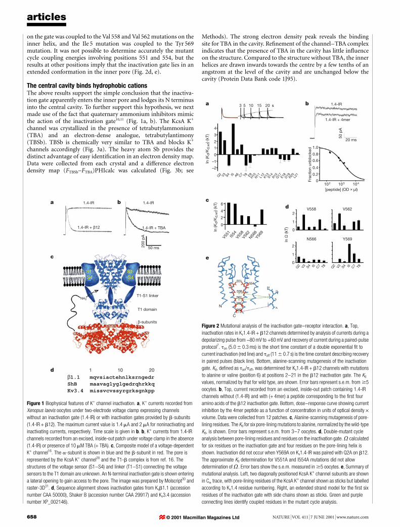
Figure 1 Biophysical features of K+ channel inactivation. a, K+ currents recorded from
Xenopus laevis oocytes under two-electrode voltage clamp expressing channels
without an inactivation gate (1.4-IR) or with inactivation gates provided by b-subunits
(1.4-IR + b12). The maximum current value is 1.4 mA and 2 mA for noninactivating and
inactivating currents, respectively. Time scale is given in b. b, K+ currents from 1.4-IR
channels recorded from an excised, inside-out patch under voltage clamp in the absence
(1.4-IR) or presence of 10 mM TBA (+ TBA). c, Composite model of a voltage-dependent
K+ channel16. The a-subunit is shown in blue and the b-subunit in red. The pore is
represented by the KcsA K+ channel20 and the T1-b complex is from ref. 16. The
structures of the voltage sensor (S1±S4) and linker (T1±S1) connecting the voltage
sensors to the T1 domain are unknown. An N-terminal inactivation gate is shown entering
a lateral opening to gain access to the pore. The image was prepared by Molscript30 and
raster-3D31. d, Sequence alignment shows inactivation gates from Kvb1.1 (accession
number CAA 50000), Shaker B (accession number CAA 29917) and Kv3.4 (accession
number XP_002146).
3 5 10 15 20
V551
I554
V558
V562
N566
Y569
Q2 V3 S4 I5 C7A6 T8
Q2 V3 S4 I5 C7 T8 Q2 V3 S4 I5 C7 T8
E9H10N11 L12
K13 R15S14 G17 E18
D19R20 L21
s
V558
1.0
0.8
0.6
0.4
0.2
0
0
1
2
00
N
MQ
S
A
V
I
C
551554
558
562
566
569
2
4
4
3
2
1
0
–1
–2
6
1
2
Frac
tion
unb
lock
ed
ln Ω
(kT)ln (K
d/K
d,w
t) (k
T)
ln (K
d/K
d,w
t) (k
T)
[peptide] (OD × µl)103 104102
V562
N566 Y569
b
d
a
c
e
1.4-IR
1.4-IR + 4mer
20 ms
50 p
A
Figure 2 Mutational analysis of the inactivation gate±receptor interaction. a, Top,
inactivation rates in Kv1.4-IR + b12 channels determined by analysis of currents during a
depolarizing pulse from -80 mV to +60 mV and recovery of current during a paired-pulse
protocol7. ton (5.0 6 0.3 ms) is the short time constant of a double exponential ®t to
current inactivation (red line) and toff (11 6 0.7 s) is the time constant describing recovery
in paired pulses (black line). Bottom, alanine-scanning mutagenesis of the inactivation
gate. Kd, de®ned as ton/toff, was determined for Kv1.4-IR + b12 channels with mutations
to alanine or valine (position 6) at positions 2±21 in the b12 inactivation gate. The Kd
values, normalized by that for wild type, are shown. Error bars represent s.e.m. from $5
oocytes. b, Top, current recorded from an excised, inside-out patch containing 1.4-IR
channels without (1.4-IR) and with (+ 4mer) a peptide corresponding to the ®rst four
amino acids of the b12 inactivation gate. Bottom, dose±response curve showing current
inhibition by the 4mer peptide as a function of concentration in units of optical density ´volume. Data were collected from 12 patches. c, Alanine-scanning mutagenesis of pore-
lining residues. The Kd for six pore-lining mutations to alanine, normalized by the wild-type
Kd, is shown. Error bars represent s.e.m. from 3±7 oocytes. d, Double-mutant cycle
analysis between pore-lining residues and residues on the inactivation gate. calculated
for six residues on the inactivation gate and four residues on the pore-lining helix is
shown. Inactivation did not occur when Y569A on Kv1.4-IR was paired with Q2A on b12.
The approximate Kd determination for V551A and I554A mutations did not allow
determination of . Error bars show the s.e.m. measured in $5 oocytes. e, Summary of
mutational analysis. Left, two diagonally positioned KcsA K+ channel subunits are shown
in Ca trace, with pore-lining residues of the KcsA K+ channel shown as sticks but labelled
according to Kv1.4 residue numbering. Right, an extended strand model for the ®rst six
residues of the inactivation gate with side chains shown as sticks. Green and purple
connecting lines identify coupled residues in the mutant cycle analysis.
© 2001 Macmillan Magazines Ltd
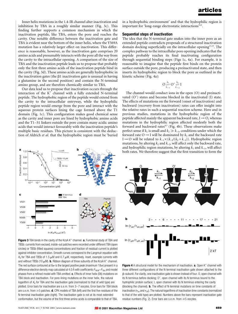
Inner helix mutations in the 1.4-IR channel alter inactivation andinhibition by TBA in a roughly similar manner (Fig. 3c). This®nding further supports a common mechanism in which theinactivation peptide, like TBA, enters the pore and reaches thecavity. One notable difference between the inactivation gate andTBA is evident near the bottom of the inner helix, where the Y569Amutation has a relatively larger effect on inactivation. This differ-ence is reasonable, however, as the inactivation gate comprises 20amino acids and presumably interacts with the pore all the way fromthe cavity to the intracellular opening. A comparison of the size ofTBA and the inactivation peptide leads us to propose that probablyonly the ®rst three amino acids of the inactivation peptide bind inthe cavity (Fig. 3d). These amino acids are generally hydrophobic inthe inactivation gates (the b1 inactivation gate is unusual in havinga glutamine in the second position) and contain the N-terminalamino group, and are therefore chemically similar to TBA.
Our data lead us to propose that inactivation occurs through theinteraction of the K+ channel with a fully extended N-terminalpeptide. The hydrophobic region of the peptide would extend fromthe cavity to the intracellular entryway, while the hydrophilicpeptide region would emerge from the pore and interact with theaqueous protein surfaces lining the cage formed above the T1domain (Fig. 1c). This con®guration makes good chemical senseas the cavity and inner pore are lined by hydrophobic amino acidsand the T1±S1 linkers outside the pore contain many acidic aminoacids that would interact favourably with the inactivation peptide'smultiple basic residues. This picture is consistent with the deduc-tion of Aldrich et al. that the hydrophobic region must be `buried
in a hydrophobic environment' and that the hydrophilic region isimportant for `long-range electrostatic interactions'4,5.
Sequential steps of inactivationThe idea that the N-terminal gate snakes into the inner pore as anextended peptide contradicts proposals of a structured inactivationdomain docking super®cially on the intracellular opening13,15. Thecomplex pathway to the intracellular pore opening indicates that thepeptide probably reaches its ®nal inactivating con®gurationthrough sequential binding steps (Figs 1c, 4a). For example, it isreasonable to imagine that the peptide ®rst binds on the proteinsurface outside the pore, producing a preinactivated state, and theninserts its hydrophobic region to block the pore as outlined in thekinetic scheme (Fig. 4a):
O Ok1
k 2 1
O9 Ok2
k 2 2
I
The channel would conduct ions in the open (O) and preinacti-vated (O9) states and become blocked in the inactivated (I) state.The effects of mutations on the forward (onset of inactivation) andbackward (recovery from inactivation) rates can offer insight intothe relative rates in such a sequential reaction scheme. Here and inprevious studies, mutations in the hydrophobic region of thepeptide affected mainly the apparent backward rate, I ! O, whereasmutations in the hydrophilic region affected modestly both theforward and backward rates4,5 (Fig. 4b). These observations makeperfect sense if k1 is small and k2 q k-1, conditions under which theforward rate O ! I will be dominated by k1 and the backward rateI ! O will be related to k-1 ´ (k-2/(k2 + k-2)). Hydrophobic regionmutations, by altering k2 and k-2, will affect only the backward rate,and hydrophilic region mutations, by altering k1 and k-1, will affectboth rates. We therefore suggest that the ®rst transition to form the
articles
NATURE | VOL 411 | 7 JUNE 2001 | www.nature.com 659
a b
c d
1.4-IR
TBA Peptide
+ TBSb 10 µM
50 ms500
pA
1.0
0.8
0.6
0.4
0.2
0
Frac
tion
unb
lock
ed
Concentration (µM)
N terminusTBA
10–1 10010–2
1 2–1 0 3 4 5
M
Q
V
S
I
102 103101
V558
V551
N566
Y569
V562
ln (Kd/Kd,wt) (kT)
Figure 3 TBA binds in the cavity of the KcsA K+ channel. a, Functional study of TBA and
TBSb: currents from excised, inside-out patches were recorded under different TBA (open
circles) or TBSb (®lled squares) concentrations and fraction of residual current is plotted
against inhibitor concentration. Smooth curves correspond to the Langmuir equation with
Kd for TBA and TBSb of 1.5 mM and 0.7 mM, respectively. Inset, example currents with
and without TBSb (10 mM). b, Ribbon diagram of three subunits of the KcsA K+ channel.
The red surface contoured at 6s is the largest positive peak (maximum 18s) present in a
difference electron density map calculated at 4.0 AÊ with coef®cients FTBSB-FTBA and model
phases from a re®ned model with TBA omitted. c, Effects of inner helix (S6) mutations on
TBA block and inactivation. For pore-lining mutations on the inner helix, the natural
logarithm of Kd for TBA and the inactivation gate (normalized to that of wild type) are
plotted. Error bars for inactivation are s.e.m. from 3±7 oocytes. Error bars for TBA block
are s.e.m. from $5 patches. d, CPK models of TBA (left) and the ®rst ®ve residues of the
N-terminal inactivation gate (right). The inactivation gate is not at its most extended
conformation, but the volume of the ®rst three amino acids is comparable to that of TBA.
2 kT
k1
k–1
k2
k–2
2
NH2
NH2
NH2
6
O O' I
11 17 21
a
b
ln (τon/τon,wt)
ln (τoff /τoff ,wt)
Figure 4 A structural model for the mechanism of inactivation. a, Open K+ channel with
three different con®gurations of the N-terminal inactivation gate shown attached to the
b-subunit. For clarity, one inactivation gate is shown instead of four. O, open channel with
its N terminus before docking; O9, open channel with its N terminus bound to the
hydrophilic protein surface; I, open channel with its N terminus entering the cavity
(blocking the channel). b, The effect of N-terminal mutations on time constants of
inactivation (ton and toff). The natural logarithms of inactivation time constants (normalized
to that of the wild type) are plotted. Numbers above the bars represent inactivation gate
residue numbers (Fig. 2). Error bars are s.e.m. from $5 oocytes.
© 2001 Macmillan Magazines Ltd

preinactivated state can be rate limiting and that the ®nal pluggingtransition can be fast, at least in some K+ channels.
One prediction made by these rate conditions is that the forwardrate of inactivation should be nearly voltage independent, as therate-limiting step occurs outside the membrane electric ®eld.Voltage-independent inactivation is observed in some K+ channels6.A second prediction of these rate conditions is that if a fraction ofchannels exists in the preinactivated state before opening of thevoltage-dependent gate, they should very rapidly inactivate uponopening. If suf®ciently rapid, the inactivation peptide would appearto produce closed-state inactivation. Apparent closed-state inactiva-tion has been documented with different inactivation gates ofthe Shaker splice variants4. Moreover, systematic truncation of theShaker D peptide hydrophilic region modulated the extent ofthe apparent closed-state inactivation, as the model in Fig. 4awould predict4.
DiscussionOur ®ndings lead us to conclude that the hydrophobic central cavityand inner pore of K+ channels form the receptor site for both theinactivation gate and quaternary ammonium compounds. Thisconclusion explains the following functional properties of inactiva-tion: a single gate is suf®cient to cause inactivation7,8; quaternaryammonium compounds compete with the inactivation gate11;external K+ pushes quaternary ammonium ions and the gate outof the pore9,21; inactivation is voltage independent6; and some K+
channels appear to exhibit closed-state inactivation4. A centralcavity receptor for molecules as large as TBA and the inactivationgate also has implications for activation gating conformations in K+
channels. In the KcsA crystal structure, the pore entryway near thecytoplasm has a diameter of about 4 AÊ . The diameter is unchangedwhen TBA is present in the cavity, but the pore must opensuf®ciently wide for TBA or the inactivation gate to reach the cavity.
Many pharmacological agents that in¯uence cation channelfunction are both hydrophobic and cationic. On the basis ofthis study, we suggest that many of these agents bind in thecavity22,23. M
MethodsMutagenesis and expression
We used rat Kv1.4-IR (residues 111±655, accession number CAA 34133) and rat b12chimaera (rat b2 core (residues 36±367, accession number CAA 54142) spliced at the Nterminus with rat b1 (residues 1±70, accession number CAA 50000))16. We introducedpoint mutations by the QuickChange method (Stratagene) and con®rmed them bysequencing the entire complementary DNA insert. We prepared RNA by T7 polymerasetranscription and injected it into Xenopus laevis oocytes24.
Electrophysiology
We used a two-electrode voltage clamp (OC-725B, Warner Instrument Corp.) to record K+
currents from oocytes 1±2 days after injection with messenger RNA. Electrodes had aresistance of ,0.5 MQ (3 M KCl). The bath solution contained (in mM): NaCl 96, KCl 2,CaCl2 0.3, MgCl2 1 and HEPES 5 at pH 7.4. Oocytes were held at -80 mV and stepped to+60 mV for 200 ms to elicit K+ current. Data collection and analysis methods are describedin ref. 16.
We recorded patch-clamp currents from inside-out, excised patches from oocytes 3±5days after injection. Electrodes were drawn from patch glass (PG150T-10, WarnerInstrument Corp.) and polished to a resistance of 0.6±1 MQ. The pipette solution(outside) contained (in mM): KCl 140, MgCl2 2 and HEPES 10 at pH 7.4. The bathsolution (inside) contained (in mM): KCl 140, EGTA 5, MgCl2 2 and HEPES 10 at pH 7.4.K+ currents were elicited by holding the patch at -100 mV and stepping to +60 mV for300 ms. Solution exchange was achieved by gravity ¯ow. Analogue data from an Axopatch-1D ampli®er (Axon Instruments) were ®ltered (3 kHz, -3 dB) by an 8-pole Bessel ®lter(Frequency Devices), digitized at 20 kHz and stored on a PC hard disk.
Synthetic peptide and blockers
Inactivation peptide (4-mer) was synthesized by the Protein/DNA technology Center ofthe Rockefeller University. Rink amide resin was used to ensure that the C terminus of thepeptide was amidated. We puri®ed peptide by reversed-phase high-performance liquidchromatography, dissolved it in bath solution and added it directly to the bath. Thepeptide amount used was quanti®ed by optical density (at 215 nm) ´ vol (ml).
We purchased TBA and TBSb from Kodak and Aldrich, respectively. We dissolved TBAor TBSb in bath solution and perfused it onto an inside-out patch by gravity ¯ow.
Crystallography
KcsA was expressed and puri®ed as described20. We incubated the chymotrypsin-cutprotein at around 10 mg ml-1 in a solution containing 150 mM KCl, 50 mM Tris (pH 7.5),2 mM DTT and 5 mM N,N-dimethyldodecylamine-N-oxide with 1 mM of TBSb or 5 mMTBA for 15±30 min at room temperature. Crystals were obtained as described20. Data werecollected under a stream of boiled-off nitrogen at stations ID-13, ESRF and X-25, NationalSynchrotron Light Source, Brookhaven National Laboratory. The TBA co-crystal dataextends to 2.8 AÊ with Rsym = 7.2%, 93% complete, redundancy ,2 and the TBSb co-crystaldata extends to 3.45 AÊ with Rsym = 7.0%, 97% complete, redundancy ,3. The data wereprocessed with Denzo and Scalepack25. All other calculations were done with the CCP4package26. The two data sets were scaled together to 4 AÊ with Rmerge = 22.5% before thecalculation of the difference electron-density map.
Analysis of inactivation, TBA block and double-mutant cycles
We determined the inactivation gate af®nity for the channel by taking the ratio ton/toff.This de®nition approximates the equilibrium constant koff/kon with two sources of error.First, even for a two-state process, ton/toff = koff/(kon + koff). Given that in most channelsstudied kon >> koff, this approximation introduces only a small error. Second, theinactivation process is not a two-state process, as discussed. In a separate analysis wemodelled inactivation as a three-step reaction with a slow ®rst and rapid second transitionand found that our analysis, assuming two states, was suf®cient for parameterization ofmutational effects. To determine ton, we ®t the inactivating current with a doubleexponential function and took the fast component (t , 50 ms, typically . 90% ofinactivation) as ton. To determine toff, we ®t the envelope of recovery in paired pulseexperiments to a single exponential function7. In some mutant channels, we had to ®trecovery with a double exponential function. We took the faster component (t , 1 s, 50±80% of current) as toff. Justi®cation for this assignment is based on previous studiesshowing that the slow component of recovery is due to C-type inactivation19,27. We veri®edthis conclusion in two ways, by raising extracellular K+ concentration to 96 mM, and byintroducing a point mutation (K533Y) at the external TEA binding site9,28. Bothmanoeuvres caused the slow component of recovery to disappear, compatible with itsdesignation as the C-type process. In the case of mutations V551A and I554A, toff was toosmall to measure accurately and so we estimated the apparent gate af®nity from thefraction of current remaining after inactivation (,87% and ,70%, respectively).
To quantify TBA, TBSb or peptide blocking, we plotted the fraction of residual currentat the end of a 300-ms pulse against blocker concentration and ®tted it with the followingequation to obtain Kd, the equilibrium dissociation constant: fraction unblocked =1/(1 + [blocker]/Kd).
We used the double-mutant cycle parameter , where
Kwt;wt
d 3 Kmut;mutd
Kwt;mutd 3 Kmut;wt
d
to quantify the degree of coupling between two mutants29. An value of more than unityindicates that the effects of two mutations are coupled. We used the mean and s.e.m. of Kd
to obtain the range of uncertainty on , assuming linear propagation of independenterrors through the above equation.
Received 5 March; accepted 19 April 2001.
1. Hoshi,T., Zagotta, W. N. & Aldrich, R. W. Biophysical and molecular mechanisms of Shaker
potassium channel inactivation. Science 250, 533±538 (1990).
2. Zagotta, W. N., Hoshi, T. & Aldrich, R. W. Restoration of inactivation in mutants of Shaker potassium
channels by a peptide derived from ShB. Science 250, 568±571 (1990).
3. Rettig, J. et al. Inactivation properties of voltage-gated K+ channels altered by presence of b-subunit.
Nature 369, 289±294 (1994).
4. Murrell-Langnado, R. D. & Aldrich, R. W. Interactions of amino terminal domains of Shaker K
channels with a pore blocking site studied with synthetic peptides. J. Gen. Physiol. 102, 949±975
(1993).
5. Murrell-Langnado, R. D. & Aldrich, R. W. Energetics of Shaker K channels block by inactivation
peptides. J. Gen. Physiol. 102, 977±1003 (1993).
6. Zagotta, W. N. & Aldrich, R. W. Voltage-dependent gating of Shaker A-type potassium channel in
Drosophila muscle. J. Gen. Physiol. 95, 29±60 (1990).
7. MacKinnon, R., Aldrich, R. W. & Lee, A. W. Functional stoichiometry of Shaker potassium channel
inactivation. Science 262, 757±759 (1993).
8. Gomez-Lagunas, F. & Armstrong, C. M. Inactivation in ShakerB K+ channels: a test for the number of
inactivating particles on each channel. Biophys. J. 68, 89±95 (1995).
9. Demo, S. D. & Yellen, G. The inactivation gate of the Shaker K+ channel behaves like an open-channel
blocker. Neuron 7, 743±753 (1991).
10. Armstrong, C. M. Interaction of tetraethylammonium ion derivatives with the potassium channels of
giant axons. J. Gen. Physiol. 58, 413±437 (1971).
11. Choi, K. L., Aldrich, R. W. & Yellen, G. Tetraethylammonium blockade distinguishes two inactivation
mechanisms in voltage-activated K+ channels. Proc. Natl Acad. Sci. USA 88, 5092±2095 (1991).
12. Isacoff, E. Y., Jan, Y. N. & Jan, L. Y. Putative receptor for the cytoplasmic inactivation gate in the Shaker
K+ channel. Nature 353, 86±90 (1991).
13. Antz, C. et al. NMR structure of inactivation gates from mammalian voltage-dependent potassium
channels. Nature 385, 272±275 (1997).
14. Schott, M. K., Antz, C., Frank, R., Ruppersberg, J. P. & Kalbitzer, H. R. Structure of the inactivating
gate from the Shaker voltage gated K+ channel analyzed by NMR spectroscopy. Eur. Biophys. J. 27, 99±
104 (1998).
15. Antz, C. & Fakler, B. Fast inactivation of voltage-gated K+ channels: From cartoon to structure. News
Physiol. Sci. (Bethesda) 13, 177±182 (1998).
16. Gulbis, J. M., Zhou, M., Mann, S. & MacKinnon, R. Structure of the cytoplasmic b subunit-T1
assembly of voltage-dependent K+ channels. Science 289, 123±127 (2000).
articles
660 NATURE | VOL 411 | 7 JUNE 2001 | www.nature.com© 2001 Macmillan Magazines Ltd
17. Kobertz, W. R., Williams, C. & Miller, C. Hanging gondola structure of the T1 domain in a voltage-
gated K+channel. Biochemistry 39, 10347±10352 (2000).
18. Sokolova, O., Kolmakova-Partensky, L. & Grigorieff, N. Three-dimensional structure of a voltage-
gated potassium channel at 2.5 nm resolution. Structure 9, 215±220 (2001).
19. Heinemann, S. H., Rettig, J., Graack, H. R. & Pongs, O. Functional characterization of Kv channel
beta-subunits from rat brain. J. Physiol. (Lond.) 493, 625±633 (1996).
20. Doyle, D. A. et al. The structure of the potassium channel: molecular basis of K+ conduction and
selectivity. Science 280, 69±77 (1998).
21. Armstrong, C. M. & Hille, B. The inner quaternary ammonium ion receptor in potassium channels of
the node of Ranvier. J. Gen. Physiol. 59, 388±400 (1972).
22. Yarov-Yarovoy, V. et al. Molecular determinants of voltage-dependent gating and binding of pore-
blocking drugs in transmembrane segment IIIS6 of the Na+ channel alpha subunit. J. Biol. Chem. 276,
20±27 (2001).
23. Mitcheson, J. S., Chen, J., Lin, M., Culberson, C. & Sanguinetti, M. C. A structural basis for drug-
induced long QT syndrome. Proc. Natl Acad. Sci. USA 97, 12329±12333 (2000).
24. Lu, Z. & MacKinnon, R. A conductance maximum observed in an inward-recti®er potassium channel.
J. Gen. Physiol. 104, 477±486 (1994).
25. Otwinowski, Z. in Proceedings of the CCP4 Study Weekend (SERC Daresbury Laboratory, Daresbury,
UK, 1993).
26. Collaborative Computational Project Number 4. The CCP4 suite: programs for protein crystal-
lography. Acta Crystallogr. D 50, 760±763 (1994).
27. Rasmusson, R. L. et al. C-type inactivation controls recovery in a fast inactivation cardiac K +channel
(Kv1.4) expressed in Xenopus oocytes. J. Physiol. (Lond.) 489, 709±721 (1995).
28. MacKinnon, R. & Yellen, G. Mutations affecting TEA blockade and ion permeation in voltage-
activated K+ channels. Science 250, 276±279 (1990).
29. Hidalgo, P. & MacKinnon, R. Revealing the architecture of a K+ channel pore through mutant cycles
with a peptide inhibitor. Science 268, 307±310 (1995).
30. Kraulis, P. MOLSCRIPT: a program to produce both detailed and schematic plots of protein
structures. J. Appl. Crystallogr. 24, 946±950 (1991).
31. Merritt, E. A. & Bacon, D. J. Raster3D: Photorealistic molecular gaphics. Methods Enzymol. 277, 505±
524 (1997).
Acknowledgements
We acknowledge the European Synchrotron Radiation Facility (ESRF) and the NationalSynchrotron Light Source (NSLS) at Brookhaven National Laboratory (with support bythe U.S. D.O.E., Division of Material Sciences and Division of Chemical Sciences). Wethank C. Petosa and A. Perrakis for help on ESRF ID-13, and M. Becker for help on NSLSX-25. The project was supported by an NIH grant to R.M. R.M. is an investigator in theHoward Hughes Medical Institute.
Correspondence and requests for materials should be addressed to R.M.(e-mail: [email protected]). Coordinates have been deposited with theProtein Data Bank under accession code 1J95.
articles
NATURE | VOL 411 | 7 JUNE 2001 | www.nature.com 661© 2001 Macmillan Magazines Ltd