5680 operator manual 330459 rev13 en · the solution tank. located on the operator console. located...
TRANSCRIPT

R
5680
330459Rev. 13 (05-2016)
Operator Manual
*330459*
English EN
(Battery)
For the latest Parts manuals and otherlanguage Operator manuals, visit:
www.tennantco.com/manuals

INTRODUCTION
Thismanual is furnishedwith each newmodel. It provides necessary operation andmaintenance instructions.
Read this manual completely and understandthe machine before operating or servicing it.
This machine will provide excellent service. However, the best results will be obtained at minimum costs if:
S The machine is operated with reasonable care.
S The machine is maintained regularly - per the machine maintenance instructions provided.
S The machine is maintained with manufacturer supplied or equivalent parts.
PROTECT THE ENVIRONMENTPlease dispose of packaging materials, used components such as batteries andfluids in an environmentally safe way according to local waste disposal regulations.Always remember to recycle.
Model No. -
Serial No. -
Installation Date -
Please fill out at time of installation for future reference.MACHINE DATA
INTENDED USE
The 5680 walk behind scrubber is designed to scrub hard surfaces (concrete, asphalt, stone,synthetic,etc) in an indoor environment. Typical applications include hotels, schools, hospitals, factories,shops, offices, and rental businesses. Do not use this machine on carpeted surfaces. Use onlyrecommended pads and commercially available floor cleaners intended for machine application. Do notuse this machine other than described in this Operator Manual.
TENNANT N.V.Industrielaan 6 5405 ABP.O. Box 6 5400 AA Uden- The Netherlands
Specifications and parts are subject to change without notice.
Original instructions, copyright E 2008- 2016 TENNANT Company, Printed in The Netherlands.

CONTENTS
15680 330459 (05- 2016)
CONTENTS
PageIMPORTANT SAFETY INSTRUCTIONS 3.
OPERATION 6. . . . . . . . . . . . . . . . . . . . . . . . . . . .MACHINE COMPONENTS 6. . . . . . . . . . . .CONTROL PANEL SYMBOLS 7. . . . . . . . .CONTROLS AND INSTRUMENTS 8. . . . . .STEERING HANDLES 9. . . . . . . . . . . . . . . .ON-OFF KEY SWITCH 10. . . . . . . . . . . . . . . .SCRUB SWITCH 11. . . . . . . . . . . . . . . . . . . . .SCRUB HEAD STRAP (DISC HEAD) 11. . .SQUEEGEE LEVER 11. . . . . . . . . . . . . . . . . .HOURMETER 12. . . . . . . . . . . . . . . . . . . . . . . .BATTERY DISCHARGE INDICATOR 12. . . .FaST SWITCH (OPTION) 12. . . . . . . . . . . . .ec- H2O SWITCH (OPTION) 13. . . . . . . . . . .EMERGENCY SHUT-OFF BUTTON 13. . . .SOLUTION FLOW LEVER 13. . . . . . . . . . . . .ec-H2O NanoClean SOLUTION FLOWSETTING 14. . . . . . . . . . . . . . . . . . . . . . . . . . . .SOLUTION TANK HOSE 14. . . . . . . . . . . . . .RECOVERY TANK DRAIN HOSE 14. . . . . . .SUPPORT ARM 14. . . . . . . . . . . . . . . . . . . . . .STOP ARM 15. . . . . . . . . . . . . . . . . . . . . . . . . .SQUEEGEE DOWN PRESSURE CAMS 15PARKING BRAKE 15. . . . . . . . . . . . . . . . . . . .HOW THE MACHINE WORKS 16. . . . . . . . .FaST SCRUBBING SYSTEM (OPTION) 17.ec- H2O NanoClean SCRUBBINGSYSTEM (ec-H2O Model) 17. . . . . . . . . . . . .BRUSH AND PAD INFORMATION 18. . . . . .WHILE OPERATING THE MACHINE 19. . . .PRE-OPERATION CHECKLIST 20. . . . . . . .ec- H2O NanoClean WATER CONDITIONINGCARTRIDGE (ec-H2O NanoClean Model) 21INSTALLING FaST PAK AGENT(OPTION) 22. . . . . . . . . . . . . . . . . . . . . . . . . . .STARTING THE MACHINE 24. . . . . . . . . . . .FILLING THE TANKS 24. . . . . . . . . . . . . . . . .SCRUBBING 26. . . . . . . . . . . . . . . . . . . . . . . . .DOUBLE SCRUBBING 29. . . . . . . . . . . . . . . .STOP SCRUBBING 30. . . . . . . . . . . . . . . . . . .DRAINING AND CLEANING THE TANKS 31RECOVERY TANK 31. . . . . . . . . . . . . . . . . . . .SOLUTION TANK 35. . . . . . . . . . . . . . . . . . . .STOP THE MACHINE 36. . . . . . . . . . . . . . . . .MACHINE TROUBLESHOOTING 37. . . . . . .
Page
MAINTENANCE 39. . . . . . . . . . . . . . . . . . . . . . . . .MAINTENANCE CHART 39. . . . . . . . . . . . . . .LUBRICATION 41. . . . . . . . . . . . . . . . . . . . . . .REAR CASTERS 41. . . . . . . . . . . . . . . . . . . . .TRANSAXLE 41. . . . . . . . . . . . . . . . . . . . . . . . .BATTERIES 42. . . . . . . . . . . . . . . . . . . . . . . . .CHECKING THE ELECTROLYTE LEVEL 42MAINTENANCE-FREE BATTERIES 43. . . .CHECKING CONNECTIONS / CLEANING 43CHARGING THE BATTERIES 44. . . . . . . . . .CIRCUIT BREAKERS 45. . . . . . . . . . . . . . . . .ELECTRIC MOTORS 46. . . . . . . . . . . . . . . . .SCRUB HEAD 47. . . . . . . . . . . . . . . . . . . . . . .DISK BRUSH SCRUB HEAD SKIRT 47. . . .CYLINDRICAL BRUSH SCRUB HEADSKIRTS 47. . . . . . . . . . . . . . . . . . . . . . . . . . . . .ADJUSTING THE SCRUB HEAD SKIRTS 47REPLACING THE SCRUB HEAD SKIRTS 47REMOVING OR REPLACING THE SCRUBHEAD 48. . . . . . . . . . . . . . . . . . . . . . . . . . . . . .LEVELING THE SCRUB HEAD 50. . . . . . . .SCRUB BRUSHES 51. . . . . . . . . . . . . . . . . . .DISK BRUSHES AND PADS 51. . . . . . . . . . .REPLACING THE DISK BRUSHES ORPADS 51. . . . . . . . . . . . . . . . . . . . . . . . . . . . . . .CYLINDRICAL BRUSHES 54. . . . . . . . . . . . .REPLACING THE CYLINDRICALBRUSHES 54. . . . . . . . . . . . . . . . . . . . . . . . . .CHECKING AND ADJUSTINGCYLINDRICAL BRUSH PATTERN 56. . . . . .FaST SYSTEM (OPTION) 58. . . . . . . . . . . . .FaST SYSTEM MAINTENANCE 58. . . . . . . .FaST SYSTEM FILTER SCREEN 59. . . . . . .FaST SUPPLY HOSE CONNECTOR 59. . . .ec- H2O SYSTEM (OPTION) 60. . . . . . . . . . .ec-H2O NanoClean WATER CONDITIONINGCARTRIDGE REPLACEMENT 60. . . . . . . . .ec- H2O MODULE FLUSH PROCEDURE 62SQUEEGEE 63. . . . . . . . . . . . . . . . . . . . . . . . .REMOVING THE SQUEEGEEASSEMBLY 63. . . . . . . . . . . . . . . . . . . . . . . . .INSTALLING THE SQUEEGEEASSEMBLY 64. . . . . . . . . . . . . . . . . . . . . . . . .LEVELING THE SQUEEGEE 65. . . . . . . . . .

CONTENTS
5680 330459 (05- 2016)2
PageADJUSTING SQUEEGEE BLADEDEFLECTION 66. . . . . . . . . . . . . . . . . . . . . . . .SQUEEGEE BLADES 67. . . . . . . . . . . . . . . . .REPLACING OR ROTATING THE REARSQUEEGEE BLADE 67. . . . . . . . . . . . . . . . . .REPLACING OR ROTATING THE FRONTSQUEEGEE BLADE 69. . . . . . . . . . . . . . . . . .BELTS AND CHAINS 70. . . . . . . . . . . . . . . . .BRUSH DRIVE BELT 70. . . . . . . . . . . . . . . . .STATIC DRAG CHAIN 70. . . . . . . . . . . . . . . .TIRES 71. . . . . . . . . . . . . . . . . . . . . . . . . . . . . . .PUSHING AND TRANSPORTING THEMACHINE 71. . . . . . . . . . . . . . . . . . . . . . . . . . .PUSHING THE MACHINE 71. . . . . . . . . . . . .TRANSPORTING THE MACHINE 72. . . . . .MACHINE JACKING 73. . . . . . . . . . . . . . . . . .STORAGE INFORMATION 73. . . . . . . . . . . .FREEZE PROTECTION 74. . . . . . . . . . . . . . .FLUSHING ANTIFREEZE FROM ec- H2OMODULE 75. . . . . . . . . . . . . . . . . . . . . . . . . . .
SPECIFICATIONS 76. . . . . . . . . . . . . . . . . . . . . . .GENERAL MACHINEDIMENSIONS/CAPACITIES 76. . . . . . . . . . .GENERAL MACHINE PERFORMANCE 77.FaST SYSTEM (OPTION) 77. . . . . . . . . . . . .ec- H2O SYSTEM (OPTION) 77. . . . . . . . . . .POWER TYPE 78. . . . . . . . . . . . . . . . . . . . . . .TIRES 78. . . . . . . . . . . . . . . . . . . . . . . . . . . . . . .MACHINE DIMENSIONS 79. . . . . . . . . . . . . .

SAFETY PRECAUTIONS
35680 330459 (06- 2015)
IMPORTANT SAFETY INSTRUCTIONS - SAVE THESE INSTRUCTIONS
The following symbols are used throughout thismanual as indicated in their description:
WARNING: To warn of hazards or unsafepractices that could result in severepersonal injury or death.
FOR SAFETY: To identify actions thatmust be followed for safe operation ofequipment.
The following information signals potentiallydangerous conditions to the operator. Know whenthese conditions can exist. Locate all safetydevices on the machine. Report machine damageor faulty operation immediately.
WARNING: Batteries emit hydrogen gas.Explosion or fire can result. Keepsparks and open flame away. Keepcovers open when charging.
WARNING: Flammable materials cancause an explosion or fire. Do not useflammable materials in tank(s).
WARNING: Flammable materials orreactive metals can cause an explosionor fire. Do not pickup.
This machine may be equipped withtechnology that automatically communicatesover the cellular network. If the machine willbe operated where cell phone use is restrictedbecause of concerns related to equipmentinterference, please contact a Tennantrepresentative for information on how todisable the cellular communicationfunctionality.
FOR SAFETY:
1. Do not operate machine:- Unless trained and authorized.- Unless operator manual is read andunderstood.
- Under the influence of alcohol ordrugs
- While using a cell phone or othertypes of electronic devices
- Unless mentally and physicallycapable of following machineinstructions.
- If it is not in proper operatingcondition.
- In areas where flammablevapors/liquids or combustible dustsare present.
- In areas that are too dark to safely seethe controls or operate the machineunless equipped with operating lights.
- In areas with possible falling objects.
2. Before starting machine:- Check machine for fluid leaks.- Make sure all safety devices are inplace and operate properly.
3. When using machine:- Use only as described in this manual.- Go slowly on inclines and slipperysurfaces.
- Wear non- slip shoes.- Reduce speed when turning.- Use care when reversing machine.- Do not carry passengers on machine.- Keep children and unauthorizedpersons away from machine.
- Do not allow machine to be used as atoy.
- Always follow safety and traffic rules.- Report machine damage or faultyoperation immediately.
- Follow mixing, handling and disposalinstructions on chemical containers.
- Follow site safety guidelinesconcerning wet floors.

SAFETY PRECAUTIONS
5680 330459 (12- 2013)4
4. Before leaving or servicing machine:- Stop on level surface.- Set the parking brake (if so equipped).- Turn off machine and remove key.
5. When servicing machine:- All work must be done with sufficientlighting and visibility.
- Keep work area well ventilated.- Avoid moving parts. Do not wear looseclothing, jewelry and secure long hair.
- Block machine tires before jackingmachine up.
- Jack machine up at designatedlocations only. Support machine withjack stands.
- Use hoist or jack that will support theweight of the machine.
- Do not power spray or hose offmachine.
- Disconnect battery connections beforeworking on machine.
- The use of incompatible batterychargers may damage battery packsand potentially cause a fire hazard.
- Inspect charger cord regularly fordamage.
- Do not disconnect the charger DCcord from the machine receptaclewhen the charger is operating. Arcingmay result. If the charger must beinterrupted during charging,disconnect the AC power supply cordfirst.
- Avoid contact with battery acid.- Battery installation must be done bytrained personnel.
- Use a hoist or adequate assistancewhen lifting batteries.
- All repairs must be performed by atrained service mechanic.
- Do not modify the machine from itsoriginal design.
- Use Tennant supplied or approvedreplacement parts.
- Wear personal protective equipmentas needed and where recommended inthis manual.
For Safety: wear hearing protection.
For Safety: wear protective gloves.
For Safety: wear eye protection.
For Safety: wear protective dust mask.
6. When loading/unloading machineonto/off truck or trailer.- Drain tanks before loading machine.- Lower scrub head and squeegeebefore tying down machine.
- Turn off machine and remove key.- Use ramp, truck or trailer that willsupport the weight of the machine andoperator.
- Do not push the machine onto/off thetruck or trailer unless the load heightis 380 mm (15 in) or less from theground.
- Set parking brake after machine isloaded (if so equipped).
- Block machine tires.- Tie machine down to truck or trailer.
SAFETY PRECAUTIONS
55680 330459 (12- 2013)
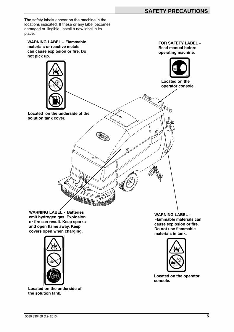
The safety labels appear on the machine in thelocations indicated. If these or any label becomesdamaged or illegible, install a new label in itsplace.
Located on the underside ofthe solution tank.
Located on the operatorconsole.
Located on theoperator console.
Located on the underside of thesolution tank cover.
353417
WARNING LABEL - Flammablematerials or reactive metalscan cause explosion or fire. Donot pick up.
FOR SAFETY LABEL -Read manual beforeoperating machine.
WARNING LABEL - Batteriesemit hydrogen gas. Explosionor fire can result. Keep sparksand open flame away. Keepcovers open when charging.
WARNING LABEL -Flammable materials cancause explosion or fire.Do not use flammablematerials in tank.

OPERATION
5680 330459 (10- 00)6
OPERATION
MACHINE COMPONENTS
A D
E
F
G
H
I
KC
M
L
A
B
C
J
N O PQ
M
A. Solution tankB. Solution tank fill openingC. Recovery tankD. Steering handlesE. SqueegeeF. Squeegee leverG. Squeegee down pressure camsH. Recovery tank drain hoseI. Solution tank hoseJ. Support armK. Stop armL. BatteriesM. Scrub headN. Scrub brush access coverO. FaST solution system (option)
ec-H2O System Module (option)P. Heavy duty scrub head strapQ. Scrub brush idler door

OPERATION
75680 330459 (10- 08)
CONTROL PANEL SYMBOLS
These symbols identify controls and displays onthe machine:
Key switch Circuit breaker #1- scrub head actuator
Variable flow or rate Circuit breaker #2- vacuum fan motor
Solution flow Circuit breaker #3- machine propel
Scrub brushes down and on Circuit breaker #4- left brush motor
Scrub brushes up and off Circuit breaker #5- right brush motor
Heavy scrub brush down pressure Circuit breaker #6- FaST
Circuit breaker #6- ec-H2O
OPERATION
5680 330459 (12- 2013)8
CONTROLS AND INSTRUMENTS
CB1
CB2
CB3
CB4
CB5
B
D
G
I
J
K
B
L
M
C
A
H
CB6
K
N
FO
E
10345
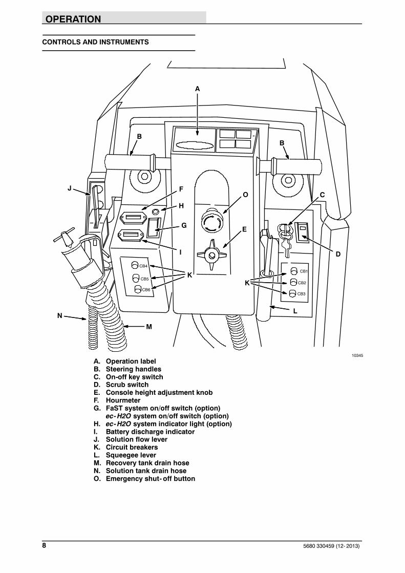
A. Operation labelB. Steering handlesC. On-off key switchD. Scrub switchE. Console height adjustment knobF. HourmeterG. FaST system on/off switch (option)
ec-H2O system on/off switch (option)H. ec-H2O system indicator light (option)I. Battery discharge indicatorJ. Solution flow leverK. Circuit breakersL. Squeegee leverM. Recovery tank drain hoseN. Solution tank drain hoseO. Emergency shut- off button

OPERATION
95680 330459 (10- 00)
STEERING HANDLES
The steering handles control the machine speedand direction.
Forward: Rotate the steering handles forward. Thefurther forward you rotate the steering handles,the faster the machine will go.
Backward: Rotate the steering handlesbackwards toward you.
Turning: Push the machine in the direction of theturn with the steering handles. The machine willturn on the swivel casters.

OPERATION
5680 330459 (10- 00)10
Stop: Release the steering handles.
The steering console height is adjustable.
Adjust: Turn the console adjustment knobcounterclockwise to loosen the knob. Move theconsole up or down to the desired height. Thenturn the knob clockwise to tighten the knob, andlock the console in position.
ON-OFF KEY SWITCH
The on-off key switch controls machine power witha key.
On: Turn the key to the right.
Off: Turn the key to the left.

OPERATION
115680 330459 (10- 08)
SCRUB SWITCH
The scrub switch controls the scrubbingoperations.
Lower brushes and start scrubbing: Press the topof the switch.
Raise brushes and stop scrubbing: Press thebottom of the switch.
NOTE: The scrub brushes do not start until thesteering handles are rotated forward or backward.
NOTE: The scrub switch also controls theFaST/ec-H2O system (option) when theFaST/ec-H2O system is enabled with theFaST/ec-H2O switch.
SCRUB HEAD STRAP (DISC HEAD)
The scrub head strap increases the scrub headpressure and puts the scrub head into heavyscrub mode.
The heavy scrub mode is used when deepscrubbing or floor stripping is necessary.
Start heavy scrub mode: With the scrub head inthe up position, pull out on the scrub head strapuntil the scrub head drops into place. Lower thebrushes and start scrubbing.
Stop heavy scrub mode: Press the bottom of thescrub switch. The scrub head will reset when itraises and stops scrubbing. When it is startedagain, the scrub head will operate at dailyscrubbing pressure.
SQUEEGEE LEVER
The squeegee lever controls the squeegee andthe vacuum system.
Lower squeegee and start vacuum: Move thesqueegee lever up and to the left to unlock it, andthen release the lever.
Raise squeegee and stop vacuum: Pull the leverup and move it to the right to lock the lever in theup position.
NOTE: Raise the squeegee before reversing themachine.
OPERATION
5680 330459 (3- 08)12
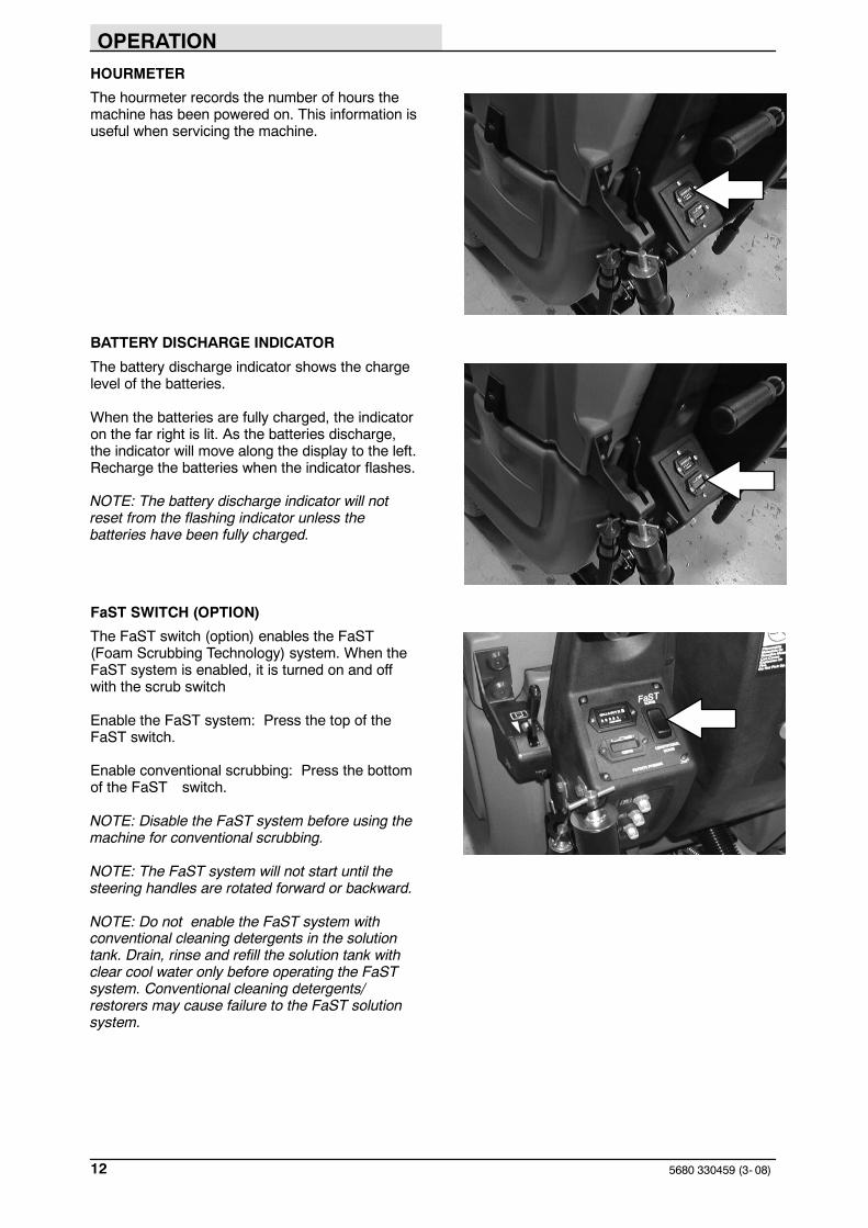
HOURMETER
The hourmeter records the number of hours themachine has been powered on. This information isuseful when servicing the machine.
BATTERY DISCHARGE INDICATOR
The battery discharge indicator shows the chargelevel of the batteries.
When the batteries are fully charged, the indicatoron the far right is lit. As the batteries discharge,the indicator will move along the display to the left.Recharge the batteries when the indicator flashes.
NOTE: The battery discharge indicator will notreset from the flashing indicator unless thebatteries have been fully charged.
FaST SWITCH (OPTION)
The FaST switch (option) enables the FaST(Foam Scrubbing Technology) system. When theFaST system is enabled, it is turned on and offwith the scrub switch
Enable the FaST system: Press the top of theFaST switch.
Enable conventional scrubbing: Press the bottomof the FaST switch.
NOTE: Disable the FaST system before using themachine for conventional scrubbing.
NOTE: The FaST system will not start until thesteering handles are rotated forward or backward.
NOTE: Do not enable the FaST system withconventional cleaning detergents in the solutiontank. Drain, rinse and refill the solution tank withclear cool water only before operating the FaSTsystem. Conventional cleaning detergents/restorers may cause failure to the FaST solutionsystem.

OPERATION
135680 330459 (06- 2015)
ec-H2O SWITCH (OPTION)
The ec-H2O switch (option) enables the ec-H2O(electrically converted water) system. When theec-H2O system is enabled, it is turned on and offwith the scrub switch.
Enable the ec-H2O system: Press the top of theec-H2O switch.
Enable conventional scrubbing: Press the bottomof the ec-H2O switch.
NOTE: Disable the ec-H2O system before usingthe machine for conventional scrubbing.
NOTE: The ec-H2O system will not start until themachine starts scrubbing.
NOTE: Do not enable the ec-H2O system withconventional cleaning detergents in the solutiontank. Drain, raise and refill the solution tank withclear cool water only before operating the ec-H2Osystem. Conventional cleaning detergents/restorers may cause failure to the ec-H2Osolution system.
EMERGENCY SHUT-OFF BUTTON
The Emergency shut- off button immediately stopsall power to the machine.
Stop machine power: Push the Emergencyshut- off button.
Restart machine power: Turn the Emergencyshut- off button to the right to release the button.Turn the key switch to the Off position, then turnthe key fully clockwise and release it to the Onposition.
Only use this button in the event of an emergency.It is not intended for routine machine shutdown.
SOLUTION FLOW LEVER
The solution flow lever controls the amount ofsolution flow to the floor.
Increase: Push the lever forward.
Decrease: Pull the lever backward.
NOTE: A solenoid valve dispenses the solution tothe scrub head. The valve opens when thesteering handles are rotated forward, and closeswhen the steering handles are released in neutralposition.
NOTE: The solution flow cannot be adjusted whenthe machine is set for FaST scrubbing or forec-H2O scrubbing on ec-H2O models manufacturedbefore ec-H2O NanoClean models.

OPERATION
5680 330459 (06- 2015)14
ec-H2O NanoClean SOLUTION FLOWSETTING
(ec-H2O models labeled ec-H2O NanoClean)
To adjust the solution flow rate when ec-H2Oscrubbing, press the solution flow button locatedon the ec-H2O module. One LED= low, twoLED’s=medium, and three LED’s= high. Theec-H2O module is located under the solution tank.Drain solution tank before lifting tank.
NOTE: For ec-H2O models manufactured beforeec-H2O NanoClean models, contact anAuthorized Service Center if solution flow rateadjustment is required.
SOLUTION TANK HOSE
The solution tank hose is used to drain thesolution tank. The drain hose plug is removed byturning the plug latch to loosen the plug andpulling the plug out of the drain hose. The drainhose is plugged by placing the hose plug in theend of the hose and turning the plug latch totighten the plug.
RECOVERY TANK DRAIN HOSE
The recovery tank drain hose is used to drain therecovery tank. The drain hose plug is removed byturning the plug latch to loosen the plug andpulling the plug out of the drain hose. The drainhose is plugged by placing the hose plug in theend of the hose and turning the plug latch totighten the plug.
SUPPORT ARM
The support arm holds up the solution tank whenthe tank is lifted. The support arm engages whenthe solution tank is lifted all the way open. Thearm is released by pulling up on it.

OPERATION
155680 330459 (06- 2015)
STOP ARM
The stop arm prevents the solution tank from fullyclosing when the tank is lowered. Push the arm into lower the solution tank completely.
SQUEEGEE DOWN PRESSURE CAMS
The squeegee down pressure cams adjust thesqueegee deflection along the entire length of thesqueegee.
Increase: Turn the cams clockwise.
Decrease: Turn the cams counter-clockwise.
PARKING BRAKE
Models manufactured after serial number 06156are equipped with a transaxle that has an electricparking brake system. The electric parking brakewill automatically engage when the steeringhandles are released. The electric parking brakewill disengage when steering handles are rotated.
Models manufactured before serial number 06156are equipped with a mechanical parking brakemechanism
The parking brake is controlled with a foot pedaland a release lever located by the squeegee.
Set: Push down on the foot pedal.
Release: Pull up on the release lever.
OPERATION
5680 330459 (12- 2013)16
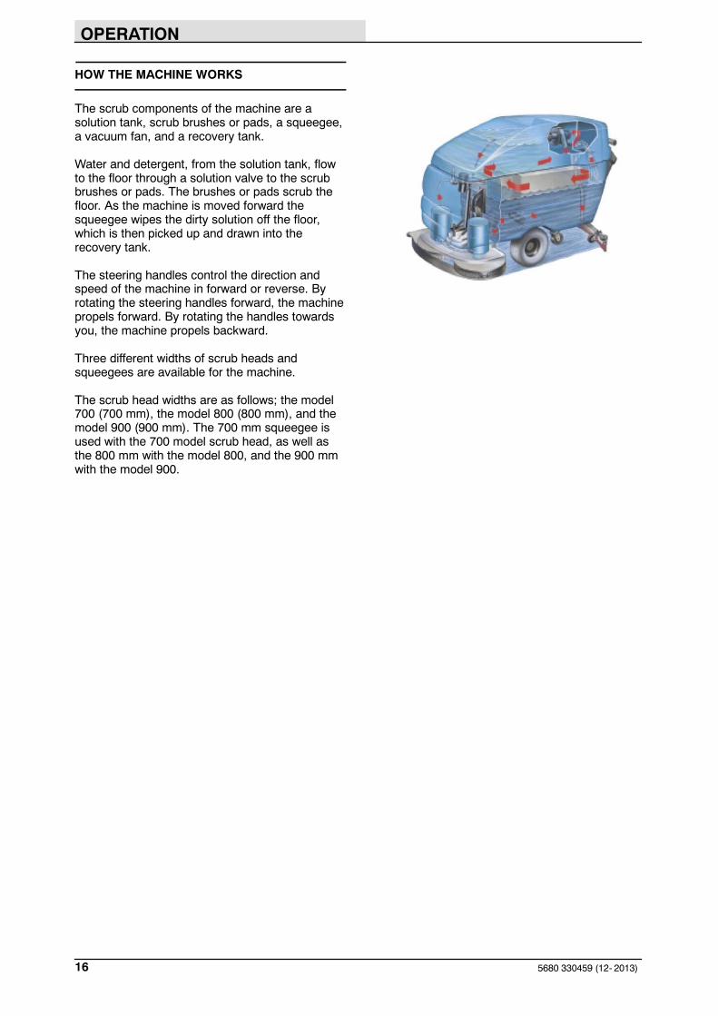
HOW THE MACHINE WORKS
The scrub components of the machine are asolution tank, scrub brushes or pads, a squeegee,a vacuum fan, and a recovery tank.
Water and detergent, from the solution tank, flowto the floor through a solution valve to the scrubbrushes or pads. The brushes or pads scrub thefloor. As the machine is moved forward thesqueegee wipes the dirty solution off the floor,which is then picked up and drawn into therecovery tank.
The steering handles control the direction andspeed of the machine in forward or reverse. Byrotating the steering handles forward, the machinepropels forward. By rotating the handles towardsyou, the machine propels backward.
Three different widths of scrub heads andsqueegees are available for the machine.
The scrub head widths are as follows; the model700 (700 mm), the model 800 (800 mm), and themodel 900 (900 mm). The 700 mm squeegee isused with the 700 model scrub head, as well asthe 800 mm with the model 800, and the 900 mmwith the model 900.

OPERATION
175680 330459 (06- 2015)
FaST SCRUBBING SYSTEM (OPTION)
The FaST (Foam Scrubbing Technology) systemoperates by injecting the FaST PAK concentrateagent (A) into the system with a small amount ofwater and compressed air. This mixture creates alarge volume of expanded wet foam.
The expanded foam mixture is then dispersedonto the floor (B) while the machine is scrubbing.When the squeegee picks up the mixture, thepatented foaming agent has collapsed and isrecovered into the recovery tank.
The FaST system can be used with all doublescrubbing and heavy duty scrubbing applications.
NOTE: Do not enable the FaST system withconventional cleaning detergents in the solutiontank. Drain, raise and refill the solution tank withclear cool water only before operating the FaSTsystem. Conventional cleaning detergents/restorers may cause failure to the FaST solutionsystem.
NOTE: Storage or transporting machinesequipped with FaST in freezing temperaturesrequires special procedures. Check with aTENNANT representative for advice.
ec-H2O NanoClean SCRUBBING SYSTEM(ec-H2O Model)
When using the ec-H2O NanoClean technology,normal water passes through a module where it iselectrically converted into a cleaning solution. Theelectrically converted water attacks the dirt,allowing the machine to easily scrub away thesuspended soil. The converted water then returnsto normal water in the recovery tank.
The ec-H2O system can be used with all doublescrubbing applications.
NOTE: Do not enable the ec-H2O system withconventional cleaning detergents in the solutiontank. Drain, raise and refill the solution tank withclear cool water only before operating the ec-H2Osystem. Conventional cleaning detergents/restorers may cause failure to the ec-H2Osolution system.
B
A

OPERATION
5680 330459 (12- 2013)18
BRUSH AND PAD INFORMATION
For best results, use the appropriate brush or padfor the cleaning application. Listed below arebrushes and pads and the applications for whicheach is best suited.
NOTE: The amount and type of soilage play animportant role in determining the type of brush orpad to use. Contact a Tennant representative forspecific recommendations.
Polypropylene brush (Cylindrical and Disk) -General purpose polypropylene bristles lift lightlycompacted dirt without scuffing high-gloss coatedfloors.
Nylon brush (Cylindrical and Disk) - Softernylon bristles are recommended for scrubbingcoated floors. Cleans without scuffing.
Super AB brush (Cylindrical and Disk) - Nylonfiber with an abrasive grit to remove stains andcompacted dirt. Aggressive action on any surface.Performs well on buildup, grease, or tire marks.
High productivity stripping pad (Black) - Foraggressive stripping of heavy finishes or sealers,or for very heavy duty scrubbing. This pad canonly be used with the grip pad driver, not thetufted pad driver.
Stripping pad (Brown)- For stripping of floorfinish to prepare the floor for recoating.
Scrubbing pad (Blue) - For medium toheavy- duty scrubbing. Removes dirt, spills, andscuffs.
Buffing pad (Red) - For light duty scrubbingwithout removing floor finish.
Polishing pad (White) - For maintaining highlypolished or burnished floors.

OPERATION
195680 330459 (12- 2013)
WHILE OPERATING THE MACHINE
Pick up oversized debris before scrubbing. Pick upwire, string, twine, large pieces of wood, or anyother debris that could become wrapped around ortangled in the brushes.
Operate the machine in a straight a path aspossible. Avoid bumping into posts or scraping thesides of the machine. Overlap the scrub paths byseveral centimeters (a few inches).
Avoid turning too sharply when the machine is inmotion. The machine is very responsive to suddenmovement. Avoid sudden turns, except inemergencies.
Adjust the brush pressure and solution flow asrequired when scrubbing. Use the lowest brushpressure and solution flow settings for bestperformance.
If poor cleaning performance is observed, stopcleaning and refer to MACHINETROUBLESHOOTING in this manual.
Operate the machine slowly on inclines. Scrubwith the machine up inclines rather than downinclines.
FOR SAFETY: When using machine, goslowly on inclines and slipperysurfaces.
Do not operate machine in areas where theambient temperature is above 43_ C (110_ F). Donot operate scrubbing functions in areas wherethe ambient temperature is below freezing 0_ C(32_ F).
The maximum rated climb and descent incline withempty tanks is 14.1%, with full tanks is 10.5%.

OPERATION
5680 330459 (12- 2013)20
PRE-OPERATION CHECKLIST
Check over this list of items before operating themachine:
- Check the battery charge level.
NOTE: The reading on the battery dischargeindicator may not be accurate when the machineis first powered on. Operate the machine a fewminutes before reading the charge level of thebatteries.
- Check under the machine for leaks.
- Check for wire, string, or twine wrappedaround the scrub brushes.
- Check the squeegees for wear or damage.
- Check the squeegee suction hose forobstructions.
- Check the recovery tank cover seals forwear or damage.
- Check that the vacuum fan inlet filter isclean.
- FaST Scrubbing: Check the FaST PAK(option) concentrate agent level, replacecarton as needed. See the INSTALLINGTHE FaST PAK AGENT section of themanual.
- FaST or ec-H2O Scrubbing: Check that allconventional cleaning agents/restorers aredrained and rinsed from the solution tank.
- FaST or ec-H2O Scrubbing: Check thatsolution tank is filled with clear cool wateronly.
- Check maintenance records to determinemaintenance requirements.
OPERATION
215680 330459 (06- 2015)
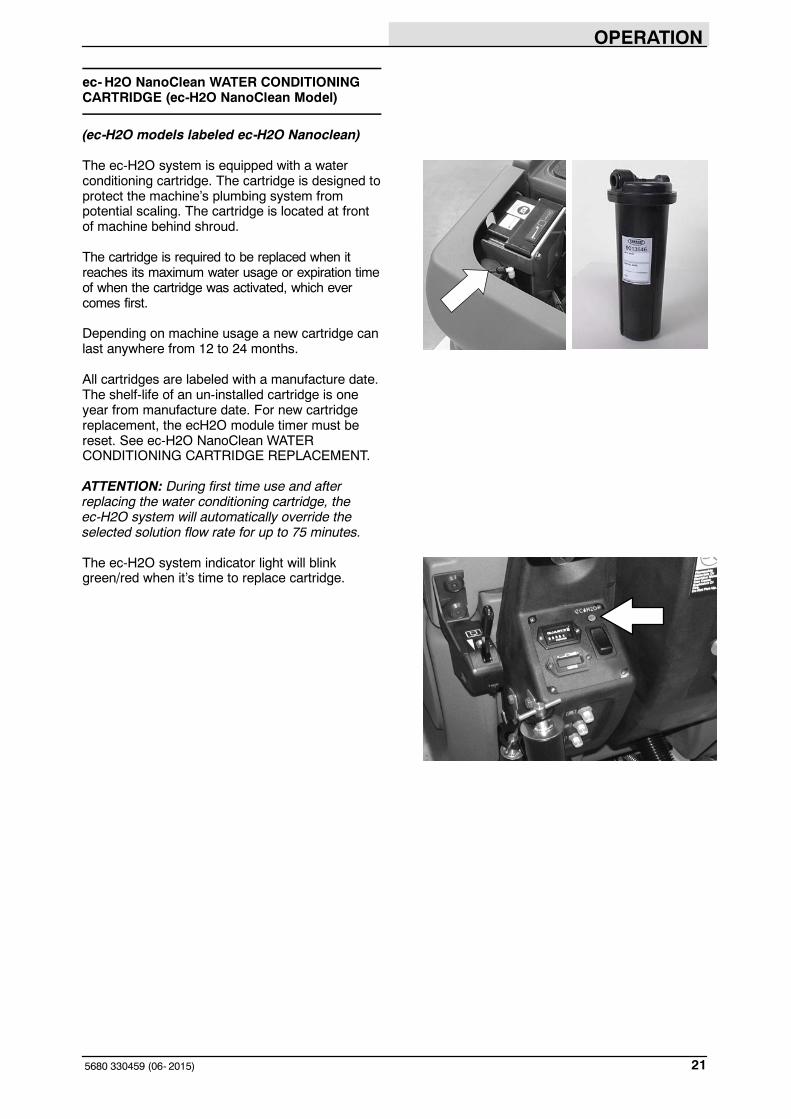
ec-H2O NanoClean WATER CONDITIONINGCARTRIDGE (ec-H2O NanoClean Model)
(ec-H2O models labeled ec-H2O Nanoclean)
The ec-H2O system is equipped with a waterconditioning cartridge. The cartridge is designed toprotect the machine’s plumbing system frompotential scaling. The cartridge is located at frontof machine behind shroud.
The cartridge is required to be replaced when itreaches its maximum water usage or expiration timeof when the cartridge was activated, which evercomes first.
Depending on machine usage a new cartridge canlast anywhere from 12 to 24 months.
All cartridges are labeled with a manufacture date.The shelf-life of an un-installed cartridge is oneyear from manufacture date. For new cartridgereplacement, the ecH2O module timer must bereset. See ec-H2O NanoClean WATERCONDITIONING CARTRIDGE REPLACEMENT.
ATTENTION: During first time use and afterreplacing the water conditioning cartridge, theec-H2O system will automatically override theselected solution flow rate for up to 75 minutes.
The ec-H2O system indicator light will blinkgreen/red when it’s time to replace cartridge.

OPERATION
5680 330459 (12- 2013)22
INSTALLING FaST PAK AGENT (OPTION)
FOR SAFETY: Before leaving orservicing machine, stop on levelsurface, set parking brake (if soequipped), turn off machine, and removekey.
NOTE: Machine must be equipped with the FaSToption before the FaST PAK agent can beinstalled.
1. Remove the perforated knock- outs from theFaST PAK Floor Cleaning Concentratecarton. Do not remove the bag from thecarton. Pull out the hose connector on thebottom of the bag and remove the hose capfrom the connector.
NOTE: The FaST PAK Floor CleaningConcentrate is specifically designed for usewith the FaST system scrubbing application.NEVER use a substitute, machine damage willresult.
FOR SAFETY: When using machine,always follow the handling instructionson chemical container.
2. Empty the solution tank. See the DRAININGAND CLEANING THE TANKS section of themanual.
NOTE: When scrubbing with the FaST systemoption, use clean water only. Do not add cleaningagents in the solution tank. Conventional cleaningagents/restorers may cause failure to the FaSTsolution system.
3. Raise the solution tank and remove the frontcover to access the FaST PAK carton.
OPERATION
235680 330459 (10- 08)
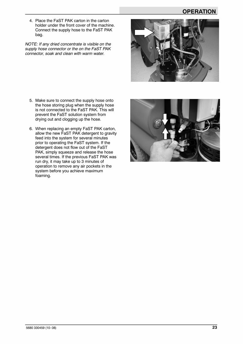
4. Place the FaST PAK carton in the cartonholder under the front cover of the machine.Connect the supply hose to the FaST PAKbag.
NOTE: If any dried concentrate is visible on thesupply hose connector or the on the FaST PAKconnector, soak and clean with warm water.
5. Make sure to connect the supply hose ontothe hose storing plug when the supply hoseis not connected to the FaST PAK. This willprevent the FaST solution system fromdrying out and clogging up the hose.
6. When replacing an empty FaST PAK carton,allow the new FaST PAK detergent to gravityfeed into the system for several minutesprior to operating the FaST system. If thedetergent does not flow out of the FaSTPAK, simply squeeze and release the hoseseveral times. If the previous FaST PAK wasrun dry, it may take up to 3 minutes ofoperation to remove any air pockets in thesystem before you achieve maximumfoaming.

OPERATION
5680 330459 (12- 2013)24
STARTING THE MACHINE
1. Turn the machine power on.
FILLING THE TANKS
1. Start the machine.
2. Drive the machine to the filling site.
3. Turn the machine power off.
FOR SAFETY: Before leaving orservicing machine, stop on levelsurface, set parking brake (if soequipped), turn off machine, and removekey.

OPERATION
255680 330459 (12- 2013)
4. CONVENTIONAL SCRUBBING: Open thesolution tank cover and partially fill thesolution tank with water. Pour the requiredamount of detergent into the solution tank fillopening. Continue filling the solution tankwith water 25 mm (1 in) below the bottom ofthe solution fill opening channel.
FOR SAFETY: When using machine,follow mixing, handling and disposalinstructions on chemical containers.
5. FaST or ec-H2O SCRUBBING: Open thesolution tank cover and fill the solution tankwith clear cool water only.
NOTE: When cleaning using the FaST orec-H2O option, USE CLEAR COOL WATERONLY. DO NOT add cleaning agents insolution tank. Conventional cleaningagents/restorers may cause failure to thesystem.
NOTE: (For conventional scrubbing)Floor conditions, water condition, amount ofsoilage, types of soilage, and brush action all playan important role in determining the type andconcentration of detergent used. For specificrecommendations, contact your Tennantrepresentative.
WARNING: Flammable materials cancause an explosion or fire. Do not useflammable materials in tank(s).
OPERATION
5680 330459 (12- 2013)26
SCRUBBING
1. Start the machine.
2. Drive the machine to the area to bescrubbed.
3. Heavy Scrub Mode only: With the scrubhead in the up position, pull out on the scrubhead strap, until the scrub head drops intoplace.
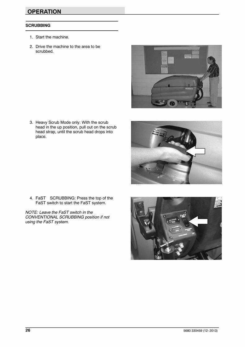
4. FaST SCRUBBING: Press the top of theFaST switch to start the FaST system.
NOTE: Leave the FaST switch in theCONVENTIONAL SCRUBBING position if notusing the FaST system.

OPERATION
275680 330459 (06- 2015)
ec-H2O SCRUBBING: Press the top of theec-H2O switch to start the ec-H2O system.
NOTE: Leave the ec-H2O switch in theCONVENTIONAL SCRUBBING position if notusing the ec-H2O system.
NOTE: The ec-H2O system indicator light will notturn on until the machine starts scrubbing.
ec-H2O NanoClean Models(ec-H2O models labeled ec-H2O Nanoclean)
ATTENTION: During first time use and afterreplacing the water conditioning cartridge, theec-H2O system will automatically override theselected solution flow rate for up to 75 minutes.
If the ec-H2O system indicator light begins to blinkgreen/red, the water conditioning cartridge needsto be replaced (See ec-H2O NanoClean WATERCONDITIONING CARTRIDGE REPLACEMENT).
ec-H2O SYSTEMINDICATOR LIGHTCODE
CONDITION
Solid green Normal operation
Blinking green/red Water conditioningcartridge expired.Replace cartridge.
Solid red Contact Service Center
ec-H2O Models(ec-H2O models manufactured before ec-H2ONanoclean models)
If an alarm sounds and the ec-H2O systemindicator light begins to blink red, the ec-H2Omodule must be flushed to resume ec-H2Ooperation (See ec-H2O MODULE FLUSHPROCEDURE)
NOTE: When the alarm sounds and the lightblinks red, the machine will bypass the ec-H2Osystem. To continue scrubbing, turn the ec-H2Oswitch off and change over to conventionalscrubbing.
ec-H2O SYSTEMINDICATOR LIGHTCODE
CONDITION
Solid green Normal operation
Blinking red Flush ec-H2O module
Solid red Contact Service Center

OPERATION
5680 330459 (06- 2015)28
5. Press the top of the scrub switch to lowerthe scrub head and begin scrubbing.
FOR SAFETY: When using machine, goslowly on inclines and slipperysurfaces.
6. Lower the squeegee to the floor with thesqueegee lever.
7. Adjust the solution flow to the floor asneeded.
NOTE: The solution flow cannot be adjusted whenthe machine is set for FaST scrubbing or forec-H2O scrubbing on ec-H2O models manufacturedbefore ec-H2O NanoClean models.
8. Drive the machine forward and scrub asrequired.
WARNING: Flammable materials orreactive metals can cause an explosionor fire. Do not pickup.

OPERATION
295680 330459 (06- 2015)
DOUBLE SCRUBBING
Double scrubbing is a method for removing heavyfloor accumulations. This is done by making twopasses over the area to be cleaned with themachine.
Double scrubbing can be performed using theFaST SCRUBBING SYSTEM (option),ec-H2O SCRUBBING SYSTEM (option) orCONVENTIONAL SCRUBBING methods.
1. First, make a pass over the area scrubbingwith the squeegee up. This dispenses thesolution/foam over the area allowing thesolution/foam to soak on the floor.
FOR SAFETY: When using machine, goslowly on inclines and slipperysurfaces.
2. Lower the squeegee to the floor with thesqueegee lever.
WARNING: Flammable materials orreactive metals can cause an explosionor fire. Do not pickup.
3. Then make a second pass scrubbing withthe squeegee down.
NOTE: Double scrubbing is not recommended inareas where the cleaning solution will run underracks or damage products.

OPERATION
5680 330459 (9- 02)30
STOP SCRUBBING
1. Release the steering handles.
2. Press the bottom of the scrub switch to stopscrubbing and raise the scrub brushes.
3. Propel the machine forward to pick up anysolution left on the floor.
4. Raise the squeegee with the squeegee lever.
OPERATION
315680 330459 (12- 2013)
DRAINING AND CLEANING THE TANKS
RECOVERY TANK
When you are finished scrubbing, or when thevacuum fan shuts off, signalling a full recoverytank, the recovery tank should be drained andcleaned. The solution tank then can be filled againfor additional scrubbing.
Clean the outside of the tank with vinyl cleaner.
1. Stop scrubbing.
2. Drive the machine next to a floor drain orsink.
3. Turn the machine power off.
FOR SAFETY: Before leaving orservicing machine, stop on levelsurface, set parking brake (if soequipped), turn off machine, and removekey.
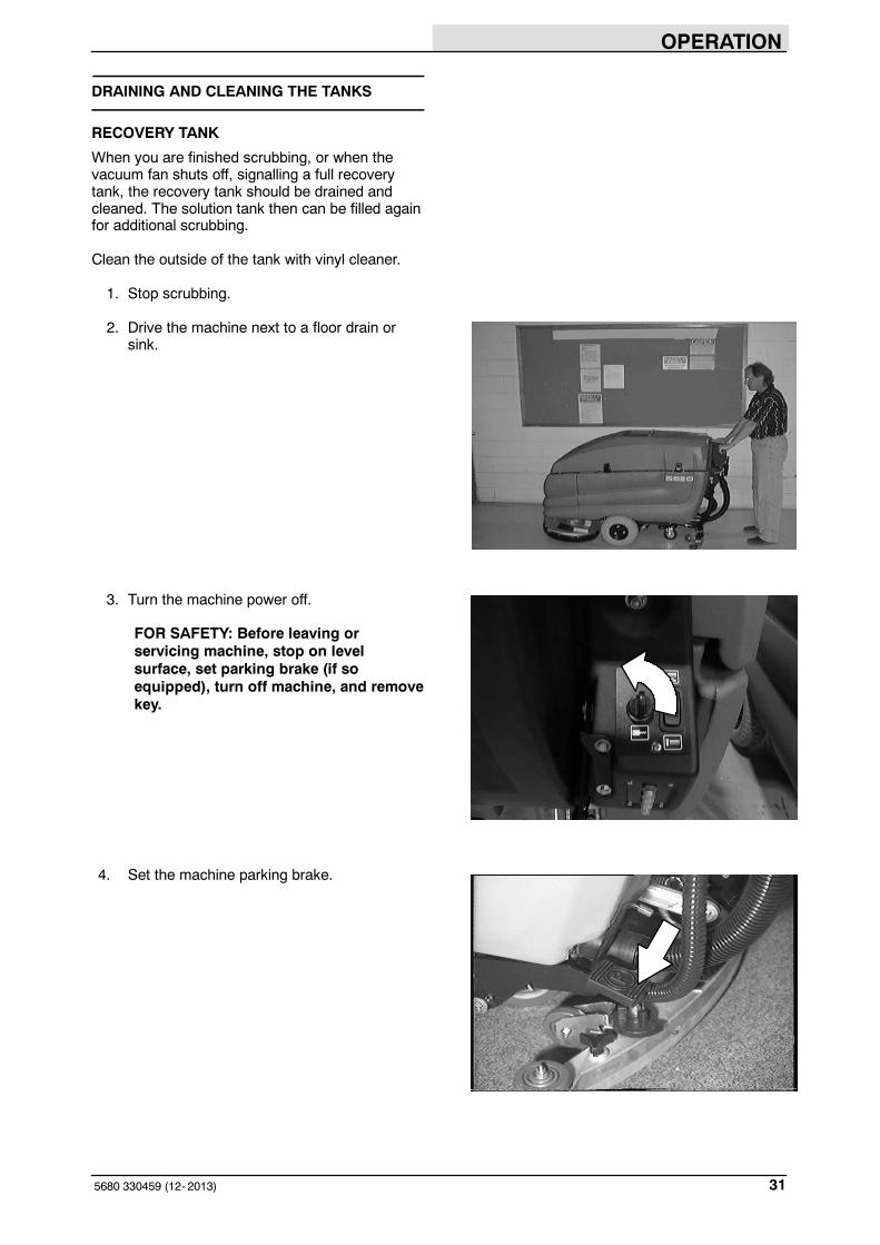
4. Set the machine parking brake.

OPERATION
5680 330459 (12- 2013)32
5. Check the solution tank, and empty anyremaining solution with the solution tankdrain hose.
6. Lift the solution tank to reach the recoverytank.
7. Remove the recovery tank drain hose fromthe mounting clip.
8. Remove the recovery tank drain hose plugwhile holding the hose up, then slowly lowerthe drain hose to the floor drain or sink.
OPERATION
335680 330459 (12- 2013)
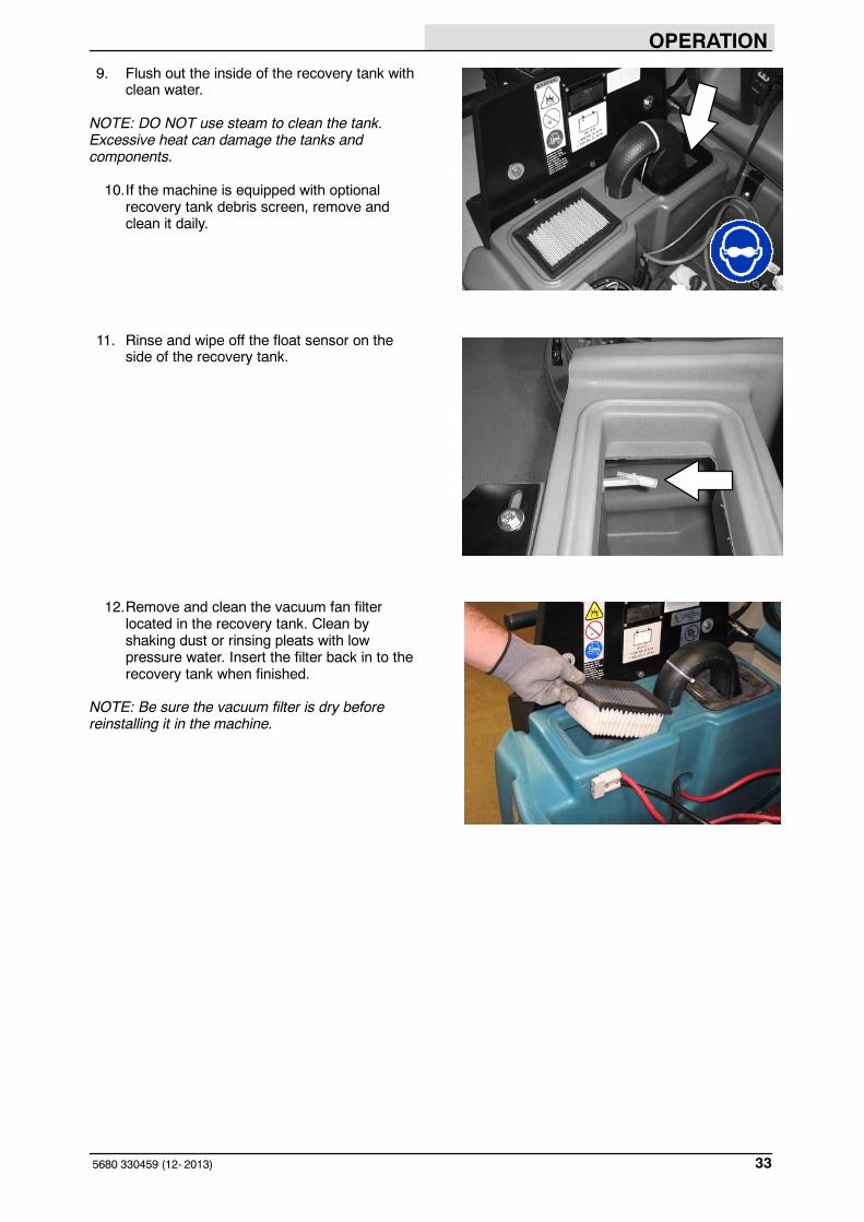
9. Flush out the inside of the recovery tank withclean water.
NOTE: DO NOT use steam to clean the tank.Excessive heat can damage the tanks andcomponents.
10.If the machine is equipped with optionalrecovery tank debris screen, remove andclean it daily.
11. Rinse and wipe off the float sensor on theside of the recovery tank.
12.Remove and clean the vacuum fan filterlocated in the recovery tank. Clean byshaking dust or rinsing pleats with lowpressure water. Insert the filter back in to therecovery tank when finished.
NOTE: Be sure the vacuum filter is dry beforereinstalling it in the machine.

OPERATION
5680 330459 (12- 2013)34
13. When the recovery and solution tanks havebeen completely drained, replace the drainhose plugs. Place the drain hoses back ontothe mounting clips on the machine.
14. Pull up on the support arm and lower thesolution tank. Push the stop arm in tocompletely lower the solution tank.
15. Cylindrical scrub head: Remove and cleanthe debris trough. Place the trough back inthe scrub head.

OPERATION
355680 330459 (12- 2013)
SOLUTION TANK
FOR SAFETY: Before leaving orservicing machine, stop on levelsurface, set parking brake (if soequipped), turn off machine, and removekey.
The solution tank stores the cleaning solution. Thesolution tank does not require regularmaintenance If deposits form on the bottom of thetank, rinse the tank with a strong blast of warmwater. The tank can be flushed through the fillopening and top access hole..
Clean the outside of the tank with vinyl cleaner.
1. Remove the solution tank drain hose fromthe mounting clip.
2. Remove the solution tank drain hose plugwhile holding the hose up, then slowly lowerthe drain hose to the floor drain or sink.
3. Rinse the tank with a strong blast of warmwater. The tank can be flushed through thefill opening and top access hole.
4. When the solution tank has been completelydrained, replace the drain hose plug. Placethe drain hose back onto the mounting clipon the machine.
The solution tank contains one standard solutionline filter. If the filter becomes dirty, the solutionflow will be reduced. Check and clean these filtersif necessary.
NOTE: DO NOT use steam to clean the tank.Excessive heat can damage the tanks andcomponents.

OPERATION
5680 330459 (12- 2013)36
STOP THE MACHINE
1. Stop scrubbing.
2. Turn the machine power off.
FOR SAFETY: Before leaving orservicing machine, stop on levelsurface, set parking brake (if soequipped), turn off machine, and removekey.
3. Set the machine parking brake.

OPERATION
375680 330459 (12- 2013)
MACHINE TROUBLESHOOTING
Problem Cause Remedy
Trailing water - poor or no waterpickup
Worn squeegee blades Rotate or replace squeegee blades
Squeegee out of adjustment Adjust squeegee
Vacuum hose clogged Flush vacuum hoses
Vacuum fan filter dirty Clean inlet filter
Debris caught on squeegee Remove debris
Vacuum hose to squeegee orrecovery tank disconnected ordamaged
Reconnect or replace vacuum hose
Solution tank not completely closed Check for obstructions
Heavy duty batteries posts too tall,file down posts
Machine front cover mounted toohigh, mount cover lower
Torn seals on solution tank Replace seals
Vacuum fan will not turn on Recovery tank full Drain recovery tank
Foam filling recovery tank Empty recovery tank
Use less or change detergent
Use a defoamer
Recovery tank sensor dirty or stuck Clean or replace
Vacuum fan circuit breaker tripped Reset circuit breaker
Little or no solution flow to the floor Solution tank empty Fill solution tank
Solution control cable broken or outof adjustment
Replace and/or adjust cable
Solution flow turned off Turn solution flow on
Solution supply lines plugged Flush solution supply lines
Solution supply line filter dirty Clean filter
Solution solenoid clogged or stuck Clean or replace
Poor scrubbing performance Debris caught on scrub brushes orpads
Remove debris
Improper detergent, brush, or padused
Contact Service Center
Worn scrub brush(es) or pad(s) Replace scrub brush(es) or pad(s)
Scrub brush motor circuit breaker(s)tripped
Reset circuit breaker(s)
Reduce scrub brush down pressure
Uneven brush pressure, level scrubhead
Contact Service Center
Low battery charge Charge batteries until the chargerautomatically turns off

OPERATION
5680 330459 (06- 2015)38
Problem Cause Remedy
Poor propelling traction Tires slip on oily or waxed floors Contact Service Center
Uneven brush down pressure Level scrub head
FaST System (option) does notoperate
FaST switch is set for Conventionalscrubbing
Set the FaST switch for FaSTsystem scrubbing
FaST circuit breaker tripped Determine cause and reset the 10Acircuit breaker button
Clogged FaST PAK supply hoseand/or connectors
Soak connector and hose in warmwater and clean
FaST PAK carton is empty or notconnected
Replace FaST PAK carton and/orconnect supply hose
Clogged flow control orifice and/orscreen
Remove and clean orifice and/orscreen
Faulty pump or air compressor Contact Service Center
Clogged filter screen Drain solution tank, remove andclean filter screen
FaST system is not primed To prime, operate the FaST solutionsystem for 3 minutes
ec-H2O NanoClean Models (ec-H2O models labeled ec-H2O NanoClean)Problem Cause Remedy
ec-H2O system indicator lightblinking green/red
Water conditioning cartridge hasexpired
Replace cartridge (See ec-H2ONanoClean WATERCONDITIONING CARTRIDGEREPLACEMENT)
ec-H2O system indicator is redor blinking* red
ec-H2O system fault has beendetected
Contact Service Center
*Verify if cleaning detergent was added to solution tank. If ec-H2O system was operated with cleaning detergent, drainsolution tank, add clear water and operate the ec-H2O system until the indicator light code clears.
ec-H2O Models (ec-H2O models manufactured before ec-H2O Nanoclean models)Problem Cause Remedy
ec- H2O system indicator lightblinking red
Mineral deposit build- up in module Flush module (See ec- H2OMODULE FLUSH PROCEDURE)
Alarm sounds
ec- H2O system indicator light solidred
Defective module Contact Service Center
ec- H2O system indicator light doesnot turn on
Defective light or module Contact Service Center
No water flow Clogged module Contact Service Center
Defective solution pump Replace solution pump
MAINTENANCE
395680 330459 (12- 2013)
MAINTENANCE
1
2
3
4
56
7
8
9
10
11
68
12
13
353417
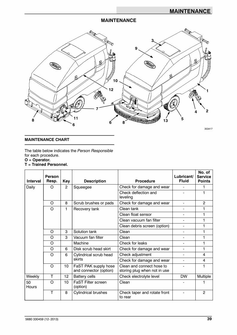
MAINTENANCE CHART
The table below indicates the Person Responsiblefor each procedure.O = Operator.T = Trained Personnel.
IntervalPersonResp. Key Description Procedure
Lubricant/Fluid
No. ofServicePoints
Daily O 2 Squeegee Check for damage and wear - 1Check deflection andleveling
- 1
O 8 Scrub brushes or pads Check for damage and wear - 2
O 1 Recovery tank Clean tank - 1Clean float sensor - 1Clean vacuum fan filter - 1Clean debris screen (option) - 1
O 3 Solution tank Clean - 1O 3 Vacuum fan filter Clean - 1O Machine Check for leaks - 1O 6 Disk scrub head skirt Check for damage and wear - 1
O 6 Cylindrical scrub headskirts
Check adjustment - 4Check for damage and wear - 4
O 10 FaST PAK supply hoseand connector (option)
Clean and connect hose tostoring plug when not in use
- 1
Weekly T 12 Battery cells Check electrolyte level DW Multiple
50Hours
O 10 FaST Filter screen(option)
Clean - 1
T 8 Cylindrical brushes Check taper and rotate frontto rear
- 2
MAINTENANCE
5680 330459 (12- 2013)40
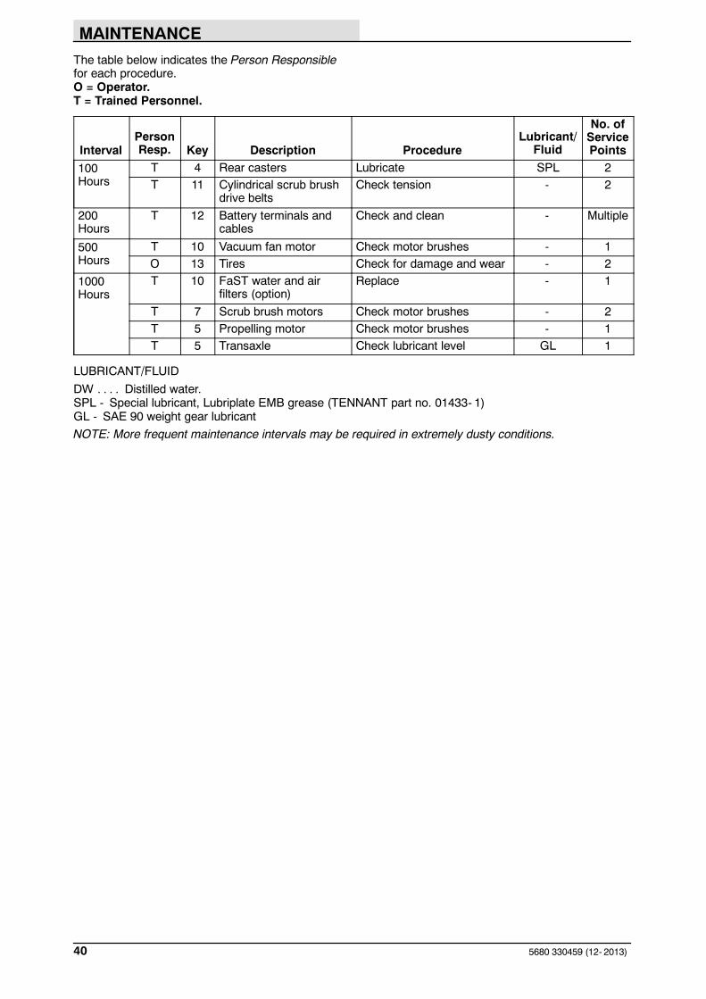
The table below indicates the Person Responsiblefor each procedure.O = Operator.T = Trained Personnel.
IntervalPersonResp. Key Description Procedure
Lubricant/Fluid
No. ofServicePoints
100Hours
T 4 Rear casters Lubricate SPL 2T 11 Cylindrical scrub brush
drive beltsCheck tension - 2
200Hours
T 12 Battery terminals andcables
Check and clean - Multiple
500Hours
T 10 Vacuum fan motor Check motor brushes - 1O 13 Tires Check for damage and wear - 2
1000Hours
T 10 FaST water and airfilters (option)
Replace - 1
T 7 Scrub brush motors Check motor brushes - 2T 5 Propelling motor Check motor brushes - 1T 5 Transaxle Check lubricant level GL 1
LUBRICANT/FLUID
DW Distilled water.. . . .SPL - Special lubricant, Lubriplate EMB grease (TENNANT part no. 01433- 1)GL - SAE 90 weight gear lubricant
NOTE: More frequent maintenance intervals may be required in extremely dusty conditions.

MAINTENANCE
415680 330459 (12- 2013)
LUBRICATION
FOR SAFETY: Before leaving orservicing machine, stop on levelsurface, set parking brake (if soequipped), turn off machine, and removekey.
REAR CASTERS
The rear casters each have one grease fitting onthe caster swivel. Lubricate the caster with agrease gun containing Lubriplate EMB grease(TENNANT part no. 01433- 1) every 100 hours ofmachine operation.
TRANSAXLE
Check the transaxle lubricant level every1000 hours of operation by removing one of theorange filler plugs. If needed, add SAE 90 weightgear lubricant.

MAINTENANCE
5680 330459 (05- 2016)42
BATTERIES
FOR SAFETY: Before leaving orservicing machine, stop on levelsurface, turn off machine, and removekey.
The lifetime of the batteries depends on theirproper maintenance. To get the most life from thebatteries;
S Do not charge the batteries more than oncea day and only after running the machine fora minimum of 15 minutes.
S Do not leave the batteries partiallydischarged for long period of time.
S Only charge the batteries in a well-ventilatedarea to prevent gas build up. Chargebatteries in areas with ambient temperatures27_C (80_F) or less.
S Allow the charger to complete charging thebatteries before re-using the machine.
S Maintain the proper electrolyte levels offlooded (wet) batteries by checking levelsweekly.
CHECKING THE ELECTROLYTE LEVEL
The flooded (wet) lead-acid batteries requireroutine watering as described below. Check thebattery electrolyte level weekly.
NOTE: Do Not check the electrolyte level if themachine is equipped with a battery wateringsystem.
FOR SAFETY: When servicing machine,keep all metal objects off batteries.Avoid contact with battery acid.
08247
MAINTENANCE
435680 330459 (05- 2016)
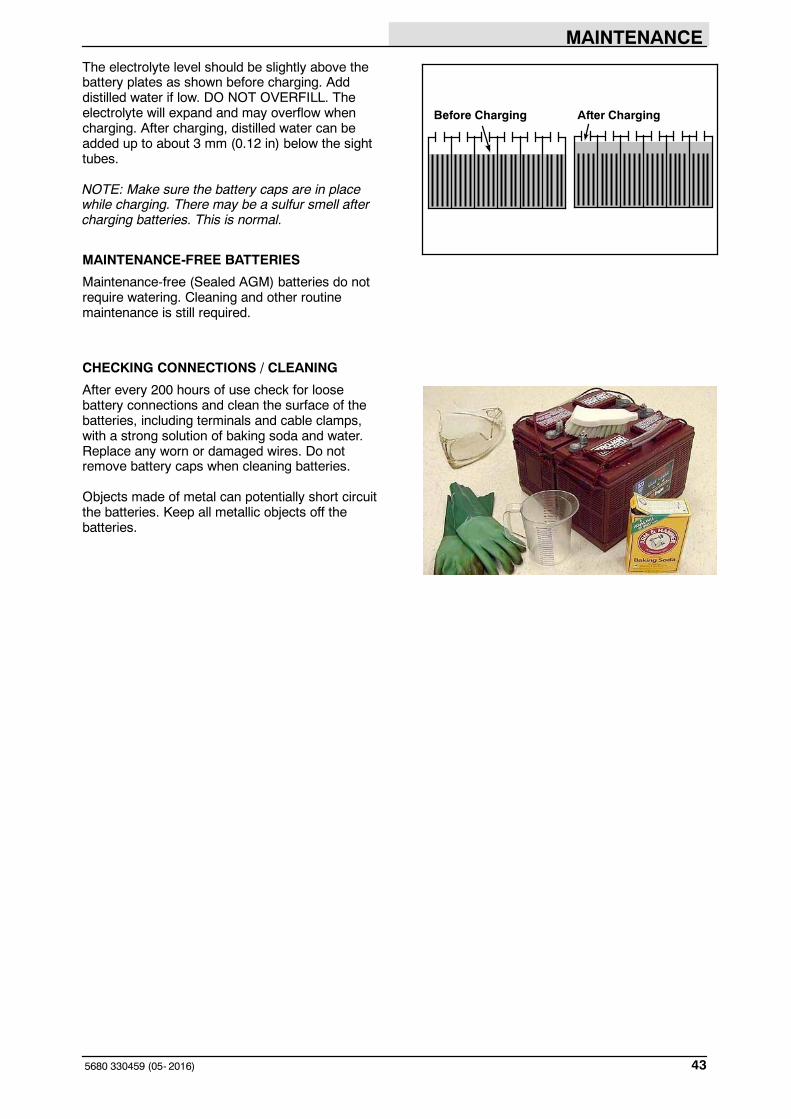
The electrolyte level should be slightly above thebattery plates as shown before charging. Adddistilled water if low. DO NOT OVERFILL. Theelectrolyte will expand and may overflow whencharging. After charging, distilled water can beadded up to about 3 mm (0.12 in) below the sighttubes.
NOTE: Make sure the battery caps are in placewhile charging. There may be a sulfur smell aftercharging batteries. This is normal.
MAINTENANCE-FREE BATTERIES
Maintenance-free (Sealed AGM) batteries do notrequire watering. Cleaning and other routinemaintenance is still required.
CHECKING CONNECTIONS / CLEANING
After every 200 hours of use check for loosebattery connections and clean the surface of thebatteries, including terminals and cable clamps,with a strong solution of baking soda and water.Replace any worn or damaged wires. Do notremove battery caps when cleaning batteries.
Objects made of metal can potentially short circuitthe batteries. Keep all metallic objects off thebatteries.
Before Charging After Charging
MAINTENANCE
5680 330459 (05- 2016)44
CHARGING THE BATTERIES
FOR SAFETY: When servicing machine,the use of incompatible battery chargersmay damage battery packs andpotentially cause a fire hazard. Inspectcharger cord regularly for damage.
1. Drive the machine to a flat, dry surface in awell-ventilated area.
2. Turn the machine power off and set theparking brake if your machine has thisoption.
FOR SAFETY: Before leaving orservicing machine, stop on levelsurface, set parking brake (if soequipped), turn off machine, and removekey.
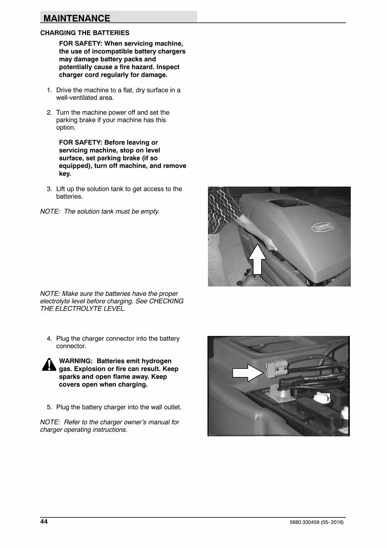
3. Lift up the solution tank to get access to thebatteries.
NOTE: The solution tank must be empty.
NOTE: Make sure the batteries have the properelectrolyte level before charging. See CHECKINGTHE ELECTROLYTE LEVEL.
4. Plug the charger connector into the batteryconnector.
WARNING: Batteries emit hydrogengas. Explosion or fire can result. Keepsparks and open flame away. Keepcovers open when charging.
5. Plug the battery charger into the wall outlet.
NOTE: Refer to the charger owner’s manual forcharger operating instructions.

MAINTENANCE
455680 330459 (05- 2016)
6. The charger will start automatically. Whenthe batteries are fully charged, the chargerwill automatically turn off.
7. After the charger has turned off, unplug thecharger from the wall outlet.
FOR SAFETY: When servicing machine,do not disconnect the charger DC cordfrom the machine receptacle when thecharger is operating. Arcing may result.If the charger must be interruptedduring charging, disconnect the ACpower supply cord first.
8. Unplug the charger connector from thebattery connector on the machine.
9. Lower the solution tank.
10. Pull up on the support arm and rotate thestop arm out of the way to allow the solutiontank to close completely.
CIRCUIT BREAKERS
The circuit breakers are resettable electrical circuitprotection devices. They stop the flow of current inthe event of a circuit overload. Once a circuitbreaker is tripped, reset manually by pressing thereset button after the breaker has cooled down.
If the overload that caused the circuit breaker totrip is still there, the circuit breaker will continue tostop current flow until the problem is corrected.
The circuit breakers are located on each side ofthe operator console.
The chart shows the circuit breakers and theelectrical components they protect.
CircuitBreaker Rating Circuit Protected
CB1 10 A Machine power
CB2 25 A Vacuum fan motor
CB3 25 A Machine propel
CB4 30 A Right brush motor
CB5 30 A Left brush motor
CB6 10 A FaST (option)
10 A ec-H2O (option)

MAINTENANCE
5680 330459 (12- 2013)46
ELECTRIC MOTORS
FOR SAFETY: Before leaving orservicing machine, stop on levelsurface, set parking brake (if soequipped), turn off machine, and removekey.
The carbon brushes on the vacuum fan motorshould be inspected after every 500 hours ofmachine operation. The carbon brushes on thescrub brush motors and propelling motor shouldbe inspected after every 1000 hours of machineoperation.

MAINTENANCE
475680 330459 (12- 2013)
SCRUB HEAD
The machine is equipped with a disk brush scrubhead. The scrub head contains skirts to controlover-spray from the scrub brushes.
DISK BRUSH SCRUB HEAD SKIRT
Make sure the scrub head skirt touches the floorall the way around when the scrub head islowered. Check the skirt for damage or wear daily.
NOTE: Replace the scrub head skirt when it isdamaged or no longer is able to touch the floor.
CYLINDRICAL BRUSH SCRUB HEAD SKIRTS
The four head skirts should just touch the floor.Check the skirts for damage or wear daily.
ADJUSTING THE SCRUB HEAD SKIRTS
1. Lower the scrub head on a level floor.
2. Turn the machine power off.
FOR SAFETY: Before leaving orservicing machine, stop on levelsurface, set parking brake (if soequipped), turn off machine, and removekey.
3. Check to see if the scrub head skirts touchthe floor.
4. If any of the skirts needs adjusting, loosenthe retainer strip hardware and slide the skirtto the proper adjustment. Tighten theretainer strip hardware.
REPLACING THE SCRUB HEAD SKIRTS
1. Raise the scrub head.
2. Turn the machine power off.
FOR SAFETY: Before leaving orservicing machine, stop on levelsurface, set parking brake (if soequipped), turn off machine, and removekey.
3. Remove the retainer strip and hardware.
4. Replace the old skirt with a new skirt andmount in place with the retainer strip andhardware.

MAINTENANCE
5680 330459 (12- 2013)48
REMOVING OR REPLACING THE SCRUBHEAD
The scrub heads are available in three widths.
NOTE: When you change to a different widthscrub head, be sure to install the appropriate widthsqueegee and machine front cover.
1. Lower the scrub head.
2. Turn the machine power off.
FOR SAFETY: Before leaving orservicing machine, stop on levelsurface, set parking brake (if soequipped), turn off machine, and removekey.
3. Remove the machine front cover.
4. Disconnect the solution line from the scrubhead tee fitting.
5. Disconnect the wire harness from eachscrub motor.
MAINTENANCE
495680 330459 (9- 02)
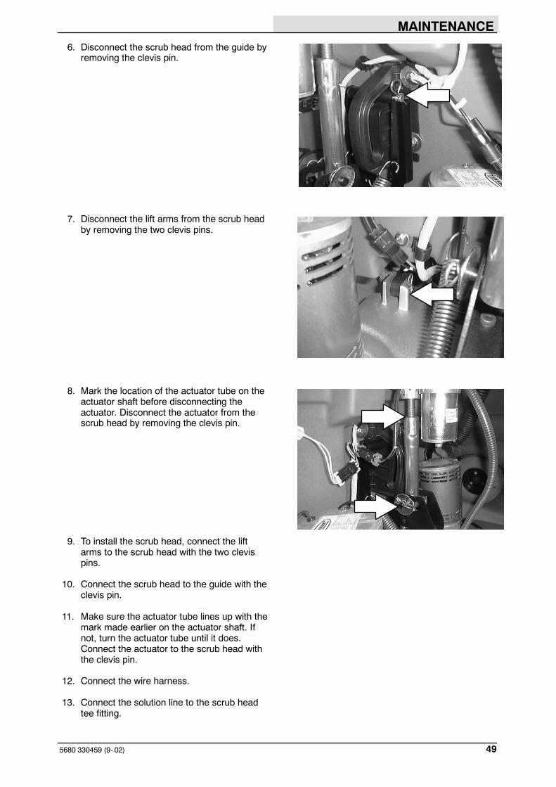
6. Disconnect the scrub head from the guide byremoving the clevis pin.
7. Disconnect the lift arms from the scrub headby removing the two clevis pins.
8. Mark the location of the actuator tube on theactuator shaft before disconnecting theactuator. Disconnect the actuator from thescrub head by removing the clevis pin.
9. To install the scrub head, connect the liftarms to the scrub head with the two clevispins.
10. Connect the scrub head to the guide with theclevis pin.
11. Make sure the actuator tube lines up with themark made earlier on the actuator shaft. Ifnot, turn the actuator tube until it does.Connect the actuator to the scrub head withthe clevis pin.
12. Connect the wire harness.
13. Connect the solution line to the scrub headtee fitting.

MAINTENANCE
5680 330459 (12- 2013)50
LEVELING THE SCRUB HEAD
1. Make sure the scrub head is lowered to thefloor.
FOR SAFETY: Before leaving orservicing machine, stop on levelsurface, set parking brake (if soequipped), turn off machine, and removekey.
2. Check the level of the scrub head bymeasuring the distance from the top of thescrub head, to the floor at all four corners.The scrub head should measure the sameon all four corners.
3. If the scrub head is not level at all fourcorners, loosen the jam nut on theadjustment screw located on the top of thescrub head. Turn the adjustment screw untilthe scrub head measures level. Tighten thejam nut.
4. Install the machine front cover.
5. Cylindrical scrub head: Check the brushpattern as described in CHECKING ANDADJUSTING CYLINDRICAL BRUSHPATTERN.

MAINTENANCE
515680 330459 (05- 2016)
SCRUB BRUSHES
The scrub brushes should be checked daily forwire or string tangled around the brush or drivehub. The brushes should also be checked for anydamage and wear.
DISK BRUSHES AND PADS
Replace the pads when they no longer cleaneffectively. Replaces the brushes when they nolonger clean effectively or when the bristles areworn to the yellow indicator.
Cleaning pads must be placed on pad drivesbefore they are ready to use. The cleaning pad isheld in place by a pad holder.
Cleaning pads need to be cleaned immediatelyafter using with soap and water. Do not wash thepads with a pressure washer. Hang dry pads, orlie flat to dry.
NOTE: Be sure to replace brushes and pads insets. Otherwise one brush or pad will be moreaggressive than the other.
REPLACING THE DISK BRUSHES OR PADS
1. Raise the scrub head.
2. Turn the machine power off.
FOR SAFETY: Before leaving orservicing machine, stop on levelsurface, set parking brake (if soequipped), turn off machine, and removekey.
3. Open the access cover on either corner ofthe scrub head.

MAINTENANCE
5680 330459 (12- 2013)52
4. Turn the brush/pad driver until you can seethe brush spring clip.
5. Press the spring clip together with yourthumb and index finger. The brush/pad driverwill drop off the drive hub.
6. Pull the brush/pad driver out from under thescrub head.

MAINTENANCE
535680 330459 (05- 2016)
7. PAD DRIVER ONLY: Press the spring cliptogether with your thumb and index finger toremove the center disk.
8. Flip or replace the scrub pad, center thescrub pad on the pad driver.
9. Set the yellow spring clip to the openposition to make brush installation easier.Press spring clip together and downward toset.
10. Align the pad driver or brush under the motorhub and push it upward to engage hub.Ensure that it is securely mounted onto themotor hub.
11. Close the scrub head access cover.
12. Repeat for the other brush/pad driver.

MAINTENANCE
5680 330459 (12- 2013)54
CYLINDRICAL BRUSHES
Check the brush taper and rotate the brushesfrom front-to-rear every 50 hours of operation, formaximum brush life and best scrubbingperformance.
Replace the brushes or pads when they no longerclean effectively.
NOTE: Be sure to replace brushes in sets.Otherwise one brush will be more aggressive thanthe other.
REPLACING THE CYLINDRICAL BRUSHES
1. Raise the scrub head.
2. Turn the machine power off and set theparking brake if your machine has thisoption.
FOR SAFETY: Before leaving orservicing machine, stop on levelsurface, set parking brake (if soequipped), turn off machine, and removekey.
3. Push down on the mounting spring and theidler door, then pull out on the bottom of thedoor. Push down on the spring until the doorreleases from the scrub head. Pull the idleplug off the brush.
4. Pull the brush out of the scrub head.
5. With the double row end of the brushtowards you, guide the brush onto the drivehub.
NOTE: Use the double rows on the idler end ofthe brush.

MAINTENANCE
555680 330459 (12- 2013)
NOTE: Cylindrical scrub brushes must be installedwith the herringbone patterns on the brushespointing towards each other for best debris pickup.
6. Insert the Idler plug of the idler door into thebrush.
7. Push down on the door to catch the door inthe scrub head, then pull up on the door tolatch it in the spring.
8. Repeat for the other brush on the other sideof the scrub head.
NOTE: The idler doors have stamped letters thatcorrespond with letters on the scrub head. Makesure the idler doors are placed back on the sameside of the scrub head that they were originallyremoved from.
MAINTENANCE
5680 330459 (12- 2013)56
CHECKING AND ADJUSTING CYLINDRICALBRUSH PATTERN
NOTE: Check the tires for correct tire pressureand make sure the solution tank is full beforechecking or adjusting the brush pattern.
1. Apply chalk, or some other material that willnot blow easily away, to a smooth, levelfloor.
2. Raise the scrub head. Position the scrubhead over the chalked area.
3. Set the parking brake if your machine hasthis option.
4. Lower the scrub head for 15 to 20 secondswhile keeping the scrub head in one spot inthe chalked area.
NOTE: If chalk or other material is not available,allow the brushes to spin on the floor for twominutes. A polish mark will remain on the floor.
5. Raise the scrub head and move the machineaway from the chalked area. Turn themachine power off.
FOR SAFETY: Before leaving orservicing machine, stop on levelsurface, set parking brake (if soequipped), turn off machine, and removekey.
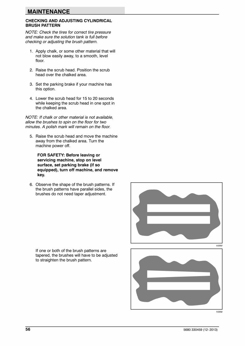
6. Observe the shape of the brush patterns. Ifthe brush patterns have parallel sides, thebrushes do not need taper adjustment.
If one or both of the brush patterns aretapered, the brushes will have to be adjustedto straighten the brush pattern.
10355
10356

MAINTENANCE
575680 330459 (12- 2013)
A. Remove the idler door by pushing downon the mounting spring and the idlerdoor, then pulling out on the bottom ofthe door. Push down on the spring untilthe door releases from the scrub head.Pull the idle plug off the brush.
B. While holding the flat end of the idlershaft with a wrench, loosen themounting screw on the outside of theidler door.
C. Turn the idler shaft to raise or lower theend of the brush as needed tostraighten the brush pattern. Tighten themounting screw.
D. Check the brush patterns again andreadjust as necessary.
The brush patterns should be the samewidth. If one is narrower then the other,loosen the jam nut on the adjustment screwlocated on the top of the scrub head.
Turn the adjustment screw clockwise toincrease the front brush pattern width. Turnthe adjustment screw counter-clockwise toincrease the back brush pattern width.Check the brush patterns again. Adjust untilthe front and back patterns are the samewidth.
Tighten the jam nut.

MAINTENANCE
5680 330459 (12- 2013)58
FaST SYSTEM (OPTION)
FaST SYSTEM MAINTENANCE
FOR SAFETY: Before leaving orservicing machine, stop on levelsurface, set parking brake (if soequipped), turn off machine, and removekey.
Every 1000 hours replace the water filter and airfilter located in the FaST detergent injector. Orderfilter kit p/n 9003009.
To access the detergent injector assembly, lowerthe scrub head and remove the front cover.
Remove the injector assembly from clamps.
Replace the water and air filter. An 8mm hexwrench required to install new water filter. Water Filter
(50 Mesh/Brown)
Air Filter(50 Mesh/Brown)

MAINTENANCE
595680 330459 (12- 2013)
FaST SYSTEM FILTER SCREEN
FOR SAFETY: Before leaving orservicing machine, stop on levelsurface, set parking brake (if soequipped), turn off machine, and removekey.
The FaST system filter screen is located underthe solution tank and filters the water from thesolution tank as it flows into the FaST system.
Remove the filter screen bowl and clean the filterscreen after every 50 hours of machine operation.Empty the solution tank before removing the filter.
FaST SUPPLY HOSE CONNECTOR
FOR SAFETY: Before leaving orservicing machine, stop on levelsurface, set parking brake (if soequipped), turn off machine, and removekey.
The FaST supply hose connector is located belowthe FaST PAK holder. Soak the connector in warmwater if detergent buildup is visible. When a FaSTPAK carton is not installed, store the supply hoseconnector on the storing plug to prevent the hosefrom clogging.
MAINTENANCE
5680 330459 (06- 2015)60
ec-H2O SYSTEM (OPTION)
ec-H2O NanoClean WATER CONDITIONINGCARTRIDGE REPLACEMENT
(ec-H2O models labeled ec-H2O NanoClean)
FOR SAFETY: Before leaving or servicingmachine, stop on level surface, set parkingbrake (if so equipped), and turn off machine.
The water conditioning cartridge is required to bereplaced when it reaches its maximum waterusage or expiration time of when the cartridge wasactivated, which ever comes first. The ec-H2Osystem indicator light will blink green/red when it’stime to replace cartridge.
Depending on machine usage, on average, a newcartridge can last anywhere from 12 months forheavy machine usage to 24 months for lightmachine usage.
ATTENTION: During first time use and afterreplacing the water conditioning cartridge, theec-H2O system will automatically override theselected solution flow rate for up to 75 minutes.
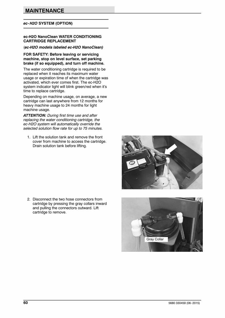
1. Lift the solution tank and remove the frontcover from machine to access the cartridge.Drain solution tank before lifting.
2. Disconnect the two hose connectors fromcartridge by pressing the gray collars inwardand pulling the connectors outward. Liftcartridge to remove.
Gray Collar
MAINTENANCE
615680 330459 (06- 2015)
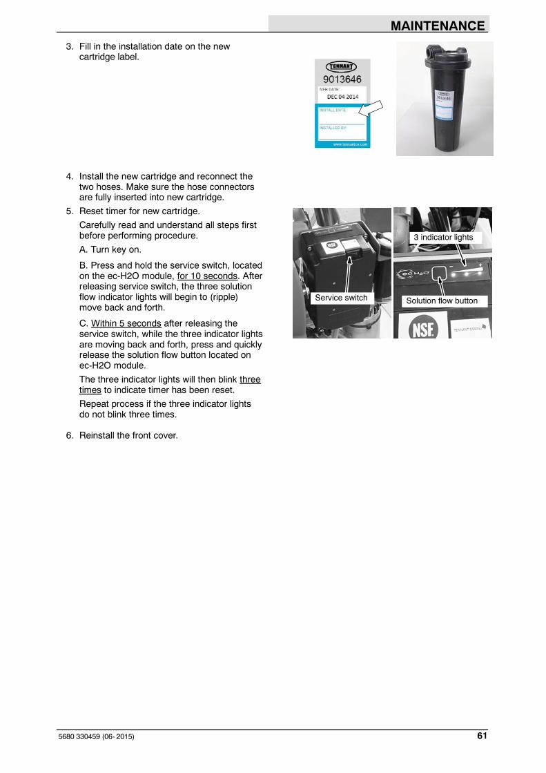
3. Fill in the installation date on the newcartridge label.
4. Install the new cartridge and reconnect thetwo hoses. Make sure the hose connectorsare fully inserted into new cartridge.
5. Reset timer for new cartridge.
Carefully read and understand all steps firstbefore performing procedure.
A. Turn key on.
B. Press and hold the service switch, locatedon the ec-H2O module, for 10 seconds. Afterreleasing service switch, the three solutionflow indicator lights will begin to (ripple)move back and forth.
C. Within 5 seconds after releasing theservice switch, while the three indicator lightsare moving back and forth, press and quicklyrelease the solution flow button located onec-H2O module.
The three indicator lights will then blink threetimes to indicate timer has been reset.
Repeat process if the three indicator lightsdo not blink three times.
6. Reinstall the front cover.
Service switch
3 indicator lights
Solution flow button

MAINTENANCE
5680 330459 (06- 2015)62
ec-H2O MODULE FLUSH PROCEDURE
(ec-H2O models manufactured before ec-H2ONanoClean models)
This procedure is only required when an alarmsounds and the ec-H2O system indicator lightbegins to blink red.
FOR SAFETY: Before leaving or servicingmachine, stop on level surface, set parkingbrake (if so equipped), and turn off machine.
1. Drain the solution tank and recovery tank ofall water.
2. Pour 2 gallons (8 liters) of white or ricevinegar into the solution tank at full strength.Do not dilute.(p/n 1050552 - Vinegar, 2.5 gals/10 ltrs)
NOTE: Use white or rice vinegar only. Theacidity level should be between 4- 8%. Do not useother acids for this procedure.
3. Disconnect the black connector fitting at thescrub head and place the hose into a bucket.To access the connector fitting, you mayhave to remove the front cover from themachine.
4. Turn the key to the on position.
5. Press and release the ec-H2O module flushswitch to start the flush cycle. The module islocated behind the front cover.
NOTE: The module will automatically shut offwhen the flush cycle is complete (approx. 7minutes). The module must run the full 7 minutecycle in order to reset the system indicator lightand alarm.
Repeat flush procedure if the ec-H2Omodule does not reset. If module fails toreset, contact an Authorized Service Center.

MAINTENANCE
635680 330459 (12- 2013)
SQUEEGEE
The squeegee assembly channels water into thevacuum fan suction. The front blade channels thewater, and the rear blade wipes the floor.
Check the squeegee blades for damage and weardaily. Rotate or replace either of the squeegeeblades if the leading edge is torn or worn half-waythrough the thickness of the blade.
The squeegee can be adjusted for leveling anddeflection. The deflection and leveling of thesqueegee blades should be checked daily, orwhen scrubbing a different type of floor.
The squeegee assembly can be removed from thesqueegee pivot to prevent damage duringtransport of the machine, or when changing to adifferent squeegee width. The squeegees areavailable in three widths to be used with the threedifferent model scrub heads; model 700 (700 mm),model 800 (800 mm), and model 900 (900 mm).
REMOVING THE SQUEEGEE ASSEMBLY
1. Raise the squeegee.
2. Turn the machine power off.
FOR SAFETY: Before leaving orservicing machine, stop on levelsurface, set parking brake (if soequipped), turn off machine, and removekey.
3. Remove the squeegee suction hose from thesqueegee.

MAINTENANCE
5680 330459 (12- 2013)64
4. Loosen the two mounting knobs.
5. Pull the squeegee off the machine.
INSTALLING THE SQUEEGEE ASSEMBLY
1. Make sure the squeegee is raised.
FOR SAFETY: Before leaving orservicing machine, stop on levelsurface, set parking brake (if soequipped), turn off machine, and removekey.
2. Place the squeegee under the squeegeepivot.
3. Slide the squeegee frame onto the squeegeepivot.
4. Tighten the mounting knobs.
5. Push the squeegee suction hose on thesqueegee.

MAINTENANCE
655680 330459 (12- 2013)
LEVELING THE SQUEEGEE
Leveling of the squeegee assures even contactthe length of the squeegee blade with the surfacebeing scrubbed. Make sure this adjustment isdone on an even, level floor.
1. Turn the machine power on.
2. Lower the squeegee.
3. Drive the machine forward, then turn themachine power off.
FOR SAFETY: Before leaving orservicing machine, stop on levelsurface, set parking brake (if soequipped), turn off machine, and removekey.
4. Look at the deflection of the squeegee blade,over the full length of the squeegee blade.
5. If the deflection is not the same over the fulllength of the blade, turn the squeegeeleveling bolt counter-clockwise to increasethe deflection at the ends of the squeegee.
Turn the squeegee leveling bolt clockwise todecrease the deflection at the ends of thesqueegee blade.
6. Drive the machine forward again with thesqueegee down to check the squeegeeblade deflection.
7. Readjust the squeegee blade deflection ifnecessary.
MAINTENANCE
5680 330459 (12- 2013)66
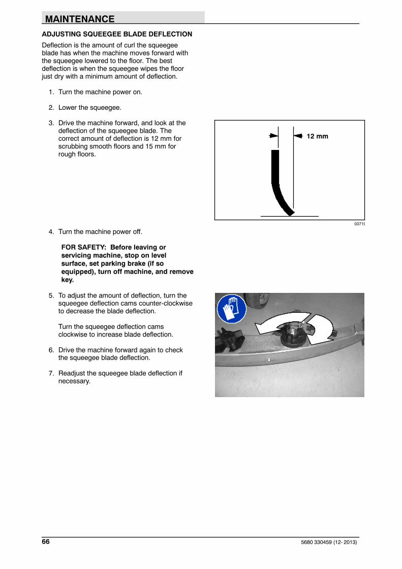
ADJUSTING SQUEEGEE BLADE DEFLECTION
Deflection is the amount of curl the squeegeeblade has when the machine moves forward withthe squeegee lowered to the floor. The bestdeflection is when the squeegee wipes the floorjust dry with a minimum amount of deflection.
1. Turn the machine power on.
2. Lower the squeegee.
3. Drive the machine forward, and look at thedeflection of the squeegee blade. Thecorrect amount of deflection is 12 mm forscrubbing smooth floors and 15 mm forrough floors.
4. Turn the machine power off.
FOR SAFETY: Before leaving orservicing machine, stop on levelsurface, set parking brake (if soequipped), turn off machine, and removekey.
5. To adjust the amount of deflection, turn thesqueegee deflection cams counter-clockwiseto decrease the blade deflection.
Turn the squeegee deflection camsclockwise to increase blade deflection.
6. Drive the machine forward again to checkthe squeegee blade deflection.
7. Readjust the squeegee blade deflection ifnecessary.
03719
12 mm

MAINTENANCE
675680 330459 (12- 2013)
SQUEEGEE BLADES
The squeegee has two squeegee blades, the frontand back. Each blade has four wiping edges. Touse them all, start with one wiping edge. To usethe next wiping edge, rotate the blade end-for-end.To use the next wiping edge, rotate the top edgesdown, bottom edges up. To use the last edge,rotate the blade end-for-end.
Replace any worn or damaged squeegee blades.
REPLACING OR ROTATING THE REARSQUEEGEE BLADE
1. Make sure the squeegee is raised off thefloor.
2. Turn the machine power off.
FOR SAFETY: Before leaving orservicing machine, stop on levelsurface, set parking brake (if soequipped), turn off machine, and removekey.
3. Loosen the two retention knobs, one at eachend on the squeegee.

MAINTENANCE
5680 330459 (12- 2013)68
4. Pull off the rear retaining band.
5. Pull off the rear squeegee blade.
6. Insert the rotated or new squeegee bladeand then insert the retainer band.
7. Tighten the two retention knobs until theends of the front and rear squeegee bladestouch. Do not over tighten.

MAINTENANCE
695680 330459 (12- 2013)
REPLACING OR ROTATING THE FRONTSQUEEGEE BLADE
1. Make sure the squeegee is raised off thefloor.
2. Turn the machine power off.
FOR SAFETY: Before leaving orservicing machine, stop on levelsurface, set parking brake (if soequipped), turn off machine, and removekey.
3. Remove the squeegee from the machine.See REMOVING THE SQUEEGEEASSEMBLY.
4. Remove the rear squeegee blade andretainer. See REPLACING OR ROTATINGTHE REAR SQUEEGEE BLADE.
5. Loosen the two remaining knobs on top ofthe squeegee assembly.
6. Pull the retainer plate back and pull out thefront squeegee blade of the squeegee frame.
7. Insert the rotated or new squeegee blade inthe squeegee frame, lining up the slots in theblade with the tabs on the retainer plate.
8. Push the retainer plate forward. Tighten thetwo outside knobs on top of the squeegeeassembly.
9. Insert the rear squeegee blade and retainer.Tighten the two rear blade retention knobsuntil the ends of the front and rear squeegeeblades touch. Do not overtighten.
10. Install the squeegee assembly on thesqueegee pivot. See INSTALLING THESQUEEGEE ASSEMBLY.
11. Adjust the squeegee blade leveling anddeflection as stated in LEVELING THESQUEEGEE and ADJUSTING SQUEEGEEBLADE DEFLECTION.

MAINTENANCE
5680 330459 (12- 2013)70
BELTS AND CHAINS
BRUSH DRIVE BELT
FOR SAFETY: Before leaving orservicing machine, stop on levelsurface, set parking brake (if soequipped), turn off machine, and removekey.
The two brush drive belts are located on thecylindrical brush scrub head. The belts drive thecylindrical brushes. Proper new belt tension is a 3mm (0.1 in) deflection from a force of 1.37 to 1.48kg (3.0 to 3.26 lb) at the belt midpoint.
When reusing an old belt, measure and record thebelt tension before removal, so that the belt canbe reinstalled at the same tension.
If the old belt tension was not recorded, therecommended force per old belts is1.03 to 1.14 kg (2.28 to 2.52 lb) with a deflectionof 3 mm (0.1 in).
Check the belt tension and wear every 100 hoursof operation.
STATIC DRAG CHAIN
A static drag chain prevents the buildup of staticelectricity in the machine. The chain is attached tothe transaxle.
Make sure the chain is always touching the floor.

MAINTENANCE
715680 330459 (06- 2015)
TIRES
FOR SAFETY: Before leaving orservicing machine, stop on levelsurface, set parking brake (if soequipped), turn off machine, and removekey.
The standard front tires are foam filled. Checktires for damage and wear after every 500 hoursof operation.
The front wheel lug nuts should be tightened to102 to 115 Nm.
PUSHING AND TRANSPORTING THEMACHINE
PUSHING THE MACHINE
If the machine becomes disabled, it can bepushed as described below.
Models manufactured after serial number 06156are equipped with an transaxle that has an electricparking brake system. To disengage the parkingbrake system, position the brake lever on thetransaxle in the down position. After pushingmachine, make sure to raise the brake lever to theup position to prevent a roll hazard.
NOTE: The power to the machine is disabledwhen brake lever is in the down position.
Models manufactured before serial number 06156perform the following procedure.
Unplug the drive motor from the electrical harnessbefore attempting to push a disabled machine.The machine will become easier to maneuverwhen it is unplugged.
ATTENTION! Do not push the machinefor a long distance and withoutunplugging the drive motor or damagemay occur to the propelling system.
Only push a disabled machine for a very shortdistance and do not exceed 3.2 kp/h. It is NOTintended to be pushed for a long distance or at ahigh speed.

MAINTENANCE
5680 330459 (12- 2013)72
TRANSPORTING THE MACHINE
1. Raise the squeegee, scrub head, andbrushes.
FOR SAFETY: When loading/unloadingmachine onto/off truck or trailer, draintanks before loading machine.
2. Load the machine using a ramp that cansupport the machine weight and personloading it.
3. Position the front of machine up against thefront of the trailer or truck. Lower the scrubhead and squeegee.
FOR SAFETY: When loading/unloadingmachine onto/off truck or trailer, lowerscrub head and squeegee before tyingdown machine.
4. Set the parking brake, if equipped, and placea block behind each wheel to prevent themachine from rolling.
FOR SAFETY: When loading/unloadingmachine onto/off truck or trailer, use aramp that can support the weight of themachine and operator. Block machinetires. Tie machine down to truck ortrailer.
5. Secure the tie- down straps to the tie- downbrackets as shown and then route thetie- down straps diagonally over the top ofthe machine. It may be necessary to installtie- down brackets to trailer or truck.
Secure the tie- down straps to the reartie- down locations on both sides of themachine frame by the rear casters.

MAINTENANCE
735680 330459 (06- 2015)
MACHINE JACKING
FOR SAFETY: Before leaving orservicing machine, stop on levelsurface, set parking brake (if soequipped), turn off machine, and removekey.
Check that both the solution and recovery tanksare empty before attempting to jack up themachine.
You can jack up the machine for service anywhereunder the recovery tank. Use a piece of wood todistribute the machine weight load.
Always stop the machine on a flat level surfaceand block the machine tires before jacking up themachine.
FOR SAFETY: When servicing machine,block machine tires before jackingmachine up. Use a hoist or jack that willsupport the weight of the machine. Jackmachine up at designated locationsonly. Support machine with jack stands.
STORAGE INFORMATION
The following steps should be taken when storingthe machine for extended periods of time.
1. Drain and clean the solution and recoverytanks.
2. Charge the batteries before storing machineto prolong the life of the batteries. Rechargebatteries once a month.
3. Disconnect batteries before storing.
4. Park the machine in a cool, dry area.

MAINTENANCE
5680 330459 (05- 2016)74
FREEZE PROTECTION
FOR SAFETY: Before leaving orservicing machine, stop on levelsurface, set parking brake (if soequipped), and turn off machine.
1. Drain the solution tank and recovery tank ofall water.
2. Pour 2 gallons (8 liters) of recreationalvehicle (RV) antifreeze into the solution tankat full strength. Do not dilute.
3. Turn the machine power on and operate thesolution flow system. Turn the machine offwhen the red RV antifreeze is visible.
Continue with the freeze protection procedure ifmachine is equipped with the ec-H2O system.
ec-H2O NanoClean Models:(ec-H2O models labeled ec-H2O NanoClean)
Operate machine in the ec-H2O mode to cycleantifreeze through ec-H2O system.
ec-H2O Models:(ec-H2O models manufactured before ec-H2ONanoClean models)
FOR SAFETY: Before leaving orservicing machine, stop on levelsurface, set parking brake (if soequipped), and turn off machine.
4. Press and release the flush switch on theec- H2O module to cycle the antifreezethrough ec- H2O system. When theantifreeze is visible, press the switch againto turn off the module. The module is locatedbehind the front cover.
IMPORTANT: Before operating machine, theantifreeze must be flushed from the module asdescribed below.
If the antifreeze is not properly flushed from theec-H2O system, the ec-H2O module may detectan error and not function (ec-H2O switch indicatorlight will turn red). If this occurs, reset key andrepeat the flush procedure as described below.

MAINTENANCE
755680 330459 (06- 2015)
FLUSHING ANTIFREEZE FROM ec-H2OMODULE
(ec-H2O models manufactured before ec-H2ONanoClean models)
FOR SAFETY: Before leaving orservicing machine, stop on levelsurface, set parking brake (if soequipped), and turn off machine.
1. Drain the antifreeze from the solution tankinto a bucket.
2. Fill the solution tank with cool water until full(See FILLING SOLUTION TANK).
3 Disconnect the black connector fitting at thescrub head and place the hose into a bucket.To access the connector fitting, you mayhave to remove the front cover from themachine.
4. Press and release the ec-H2O module flushswitch to start the flush cycle. The module islocated behind the front cover.
When the water turns clear, press themodule switch again to stop the flush cycle.
Dispose the antifreeze in an environmentally safeway according to local waste disposal regulations.
5. The machine is now ready for scrubbing.
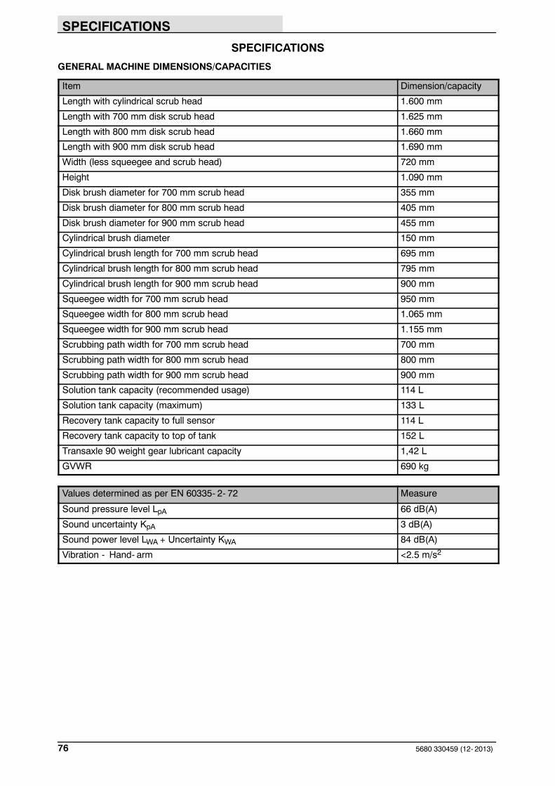
SPECIFICATIONS
5680 330459 (12- 2013)76
SPECIFICATIONS
GENERAL MACHINE DIMENSIONS/CAPACITIES
Item Dimension/capacity
Length with cylindrical scrub head 1.600 mm
Length with 700 mm disk scrub head 1.625 mm
Length with 800 mm disk scrub head 1.660 mm
Length with 900 mm disk scrub head 1.690 mm
Width (less squeegee and scrub head) 720 mm
Height 1.090 mm
Disk brush diameter for 700 mm scrub head 355 mm
Disk brush diameter for 800 mm scrub head 405 mm
Disk brush diameter for 900 mm scrub head 455 mm
Cylindrical brush diameter 150 mm
Cylindrical brush length for 700 mm scrub head 695 mm
Cylindrical brush length for 800 mm scrub head 795 mm
Cylindrical brush length for 900 mm scrub head 900 mm
Squeegee width for 700 mm scrub head 950 mm
Squeegee width for 800 mm scrub head 1.065 mm
Squeegee width for 900 mm scrub head 1.155 mm
Scrubbing path width for 700 mm scrub head 700 mm
Scrubbing path width for 800 mm scrub head 800 mm
Scrubbing path width for 900 mm scrub head 900 mm
Solution tank capacity (recommended usage) 114 L
Solution tank capacity (maximum) 133 L
Recovery tank capacity to full sensor 114 L
Recovery tank capacity to top of tank 152 L
Transaxle 90 weight gear lubricant capacity 1,42 L
GVWR 690 kg
Values determined as per EN 60335- 2- 72 Measure
Sound pressure level LpA 66 dB(A)
Sound uncertainty KpA 3 dB(A)
Sound power level LWA + Uncertainty KWA 84 dB(A)
Vibration - Hand- arm <2.5 m/s2

SPECIFICATIONS
775680 330459 (06- 2015)
GENERAL MACHINE PERFORMANCE
Item Measure
Aisle turnaround width with 700 mm scrub head 1.685 mm
Aisle turnaround width with 800 mm scrub head 1.700 mm
Aisle turnaround width with 900 mm scrub head 1.715 mm
Maximum rated climb and descent angle with empty tanks 14.1%
Maximum rated climb and descent angle with full tanks 10.5%
FaST SYSTEM (OPTION)
Item Measure
Solution pump 36 Volt DC, 5A, 5,7 LPM (1,5 GPM) open flow,45 psi bypass setting
Solution flow rate 0,83 LPM (0,22 GPM)
Detergent pump 36 Volt DC
Concentrate flow rate 0,9 CC/Minute (0,03 Ounces/Minute)
Concentrate to water dilution ratio 1:1000
Air pump 24 Volt DC, 0,6 Maximum Amp draw
Air pump flow rate 8,7 LPM (0,3 CFM) open flow
ec-H2O SYSTEM (OPTION)
Item Measure
Solution pump 36 Volt DC, 5A, 5,7 LPM (1,5 GPM) open flow,45 psi bypass setting
Solution flow rate* - Disk 700 mm 0,83 L/min / 0,22 gpm (standard)
1,25 L/min / 0,33 gpm (optional)
1,66 L/min / 0,44 gpm (optional)
Solution flow rate* - Disk 800 mm 0,83 L/min / 0,22 gpm (standard)
1,25 L/min / 0,33 gpm (optional)
1,66 L/min / 0,44 gpm (optional)
Solution flow rate* - Disk 900 mm 1,10 L/min / 0,30 gpm (standard)
1,66 L/min / 0,44 gpm (optional)
2,00 L/min / 0,53 gpm (optional)
Solution flow rate* - Cylindrical 700 mm 1,25 L/min / 0,33 gpm (standard)
1,66 L/min / 0,44 gpm (optional)
Solution flow rate* - Cylindrical 800 mm 1,25 L/min / 0,33 gpm (standard)
1,66 L/min / 0,44 gpm (optional)
Solution flow rate* - Cylindrical 900 mm 1,66 L/min / 0,44 gpm (standard)
2,00 L/min / 0,53 gpm (optional)
* ec- H2O models manufactured before ec-H2O NanoClean models - If the optional solution flow rates are required, contact anAuthorized Service Center.

SPECIFICATIONS
5680 330459 (9- 02)78
POWER TYPE
Type Quantity Volts Ah Rating Weight
Batteries 6 6 235 @ 20 hr rate 30 kg
6 6 335 @ 20 hr rate 47 kg
Type Use VDC Kw
Electric Motors Scrub brush (disk) 36 0,56
Scrub brush (cylindrical) 36 0,56
Vacuum fan 36 0,63
Propelling 36 0,37
Type VDC amp Hz Phase VAC
Chargers (Smart) 36 20 60 1 115
36 30 60 1 115
TIRES
Location Type Size
Front (2) Foam filled, non- marking 4,10/3,5 - 6
Rear, casters (2) Solid, non-marking 127 mm x 35 mm

SPECIFICATIONS
795680 330459 (9- 02)
1.625 mm1.660 mm1.690 mm
950 mm1.065 mm1.155 mm
720 mm1.090 mm
353416
MACHINE DIMENSIONS