(54) strength enhancing insert (56) references cited ...nknaik/docs/5aus_8640428_b2_4feb2014.pdf ·...
TRANSCRIPT

US008640428B2
(10) Patent N0.: US 8,640,428 B2 Naik et al. (45) Date 0f Patent: Feb. 4, 2014
(56) References Cited ASSEMBLIES
U.S. PATENT DOCUMENTS
Inventors: Niranjan Krishna Naik, Mumbai (IN)'
(12) United States Patent
(54) STRENGTH ENHANCING INSERT
<75)

US 8,640,428 B2 Page 2
(56)
4,554,196 4,671,470 4,716,067 4,729,705 4,941,785 5,053,285 5,082,405 5,091,246 5,093,957 5,240,543 5,437,750 5,451,465 5,533,693 5,536,344 5,538,781 6,055,790 6,129,122 6,264,412 6,338,367 6,394,722 6,872,273
2002/0050105
References Cited
U.S. PATENT DOCUMENTS
11/1985 6/1987 12/1987 3/1988 7/1990 10/1991 1/1992 2/1992 3/1992 8/1993 8/1995 9/1995 7/1996 7/1996 7/1996 5/2000
10/2000 7/2001 1/2002 5/2002 3/2005 5/2002
Meeker ......................... .. 428/67
Jonas .......................... .. 244/119
Moji et al. Higgins Witten Gojny et al. Witten Yasui et al. . . 442/205
Do ............... .. 16/2.1
Fetterhoff et al. . . 156/293
Rinse et al. 156/73.1 Garrioch ..................... .. 428/426
Abildskov .................. .. 244/ 131
Van Dreumel Rao et al. .................... .. 442/217
Lunde et al. Bilisik ......... .. 139/11
Nakamura et al . 411/352 Khokar ........ .. 139/11
Kuntet al. .. 411/82
Davies et al. .. . 156/148
McCorkle et al. ......... .. 52/127.1
OTHER PUBLICATIONS
Magin, Paul F., “Multidirectionally Reinforced Fabrics and Pre forms,” Engineered Materials Handbook, Composites, 1987, pp. 129-131, vol. 1, ASM International, Metals Park, OH. McAllister, Lawrence E., “Multidirectionally Reinforced Carbon/ Graphite MatriX Composites,” Engineered Materials Handbook, Composites, 1987, pp. 915-919, vol. 1, ASM International, Metals Park, OH. Naik, N. K. and V. K. Ganesh, “Failure Behavior of Plain Weave Fabric Laminates Under On-Axis UniaXial Tensile Loading: II?Analytical Predictions,” Journal of Composite Materials, 1996, pp. 1779-1822, vol. 30. Naik, N. K. and E. Sridevi, “An Analytical Method for Thermoelastic Analysis of 3D Orthogonal Interlock Woven Composites,” Journal of Reinforced Plastics and Composites, 2002, pp. 1149-1191 vol. 21. Naik, N. K. et al., “Stress and Failure Analysis of 3D Orthogonal Interlock Woven Composites,” Journal of Reinforced Plastics and Composites, 2001, pp. 1485-1523, vol. 20. Shembekar, P. S. and N. K. Naik, “Elastic Behavior of Woven Fabric Composites: II?Laminate Analysis,” Journal of Composite Materi als, 1992, pp. 2226-2246, vol. 26.
* cited by examiner

U.S. Patent Feb. 4, 2014 sheet 1 0f 11 Us 8,640,428 B2
Ww x Mmmm MW V .www
Figure 1: Through-the-thickness insert for sandwich structure.
U.S. Patent Feb. 4, 2014 sheet 2 0f 11 Us 8,640,428 B2
n
WW www m f////\ è
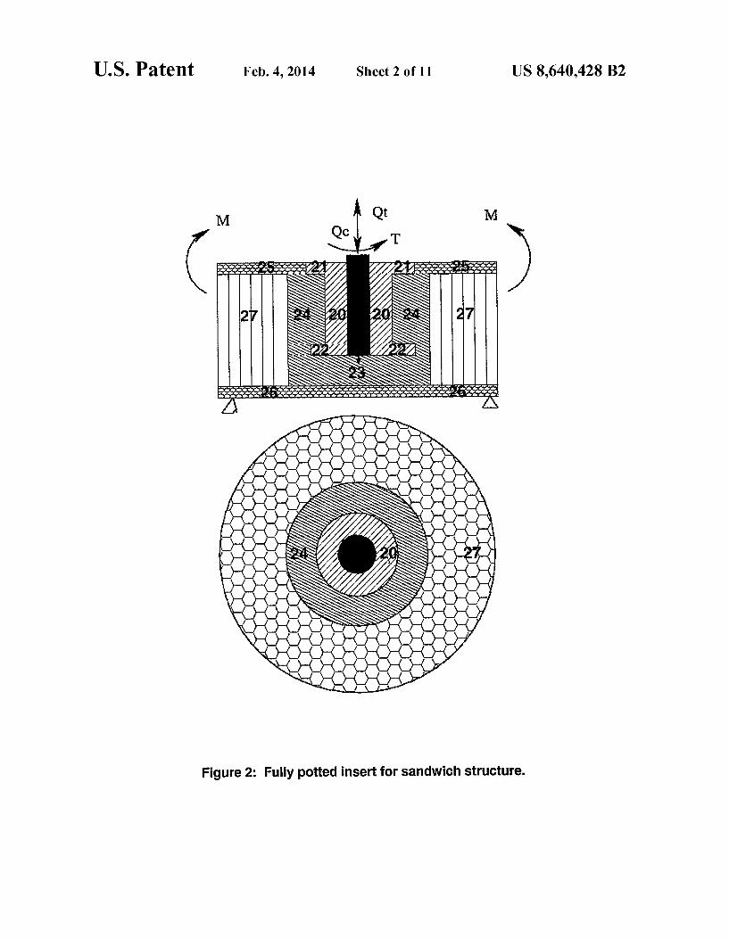
Figure 2: Fully potted insert for sandwich structure.

U.S. Patent Feb. 4, 2014 sheer 3 0f 11 US 8,640,428 B2
W ` Y, w/ „m ,www w \ /\\. www
Figure 3: Partially potted insert for sandwich structure.

U.S. Patent Feb. 4, 2014 sheet 4 0f 11 Us 8,640,428 B2
Core formulation Face-plate formulation
v v
Equilibrium equations I Classical plate theory |
V
y V + Equilibrium equations r - direction G ~ direction z direction |
¢ ¢ > Moment equilibrium Force equilibrium . 2 equations 3 equations
Core assumptions, G9 = 1,0 = o’r __» t
Stress-strain GZ: f( Z, Tm TOL , ._ _) Constitutive relations for relations for Nr', Nal, Nro', Mr', Ma', Mie',
I QrlsQGl
Trl T07. o.7. Y ` ‘y `
V r z
wc=f(z,‘c„.,t0,.,w,w, ..)
t
A Displacement n
` continuity relations '
V V l 2 l 2
ur = .zu u] ()r9 l; 0r’ In.’ U0.: Z1 u Orr u Ori Trzs T02 1
T01. 1 wir ß rv ß r» WI’ ßlr» ßzrv v v v
t
Set of governing equations
Figure 4: Flow diagram for the analytical formulation procedure.

U.S. Patent Feb. 4, 2014 sheet s 0f 11 Us 8,640,428 B2
Set of governing equations
Fiearrangement of equations i
V
24 first order coupled partial differential equations
A Fourier expansions
V
24 first order coupled exact differential equations
V Boundary conditions
V
Two point boundary value problem
Plate divided into segments along the radius
V
Initial value problems
Continuity condition at each segment
Multi-segment method of direct integration
Y
Solution for fundamental variables
Figure 5: Flow diagram for the solution procedure.

U.S. Patent Feb. 4, 2014 sheer 6 0f 11 US 8,640,428 B2
5 u u s l o i l u u
‘ I I I ' I ' I ' I
0 2 4 6 8 10
Transverse displacement, w ( mm)
Figure 6: Transverse displacement as a function of compressive load, through-the-thickness aluminum inserts.

U.S. Patent
Load, QC ( N )
6000 -1
2000 -1
Feb. 4, 2014 Sheet 7 0f 11 US 8,640,428 B2
Experimental
attachment
top tace-plate
bottom face-plate
Analytical
attachment 5
bottom face-plate
‘ l 1 l
2 4 6 8 10
Transverse displacement, w (mm)
Figure 7: Transverse displacement as a function of compressive load, through-the thickness 2D woven composite inserts.

U.S. Patent Feb. 4, 2014 sheer 8 0f 11 US 8,640,428 B2
I. l. l
l.
Il Il l
4 atttachment
6 bottom face-plate
4000
EV @c .E3
10
Transverse displacement, w (mrn)
Figure 8: Transverse displacement as a function of compressive load, through-the-thickness 3D woven composite inserts.
U.S. Patent Feb. 4, 2014 sheer 9 0f 11 US 8,640,428 B2
Failure function, l
o 2000 4000 6000 8000
Load, Qc ( N )
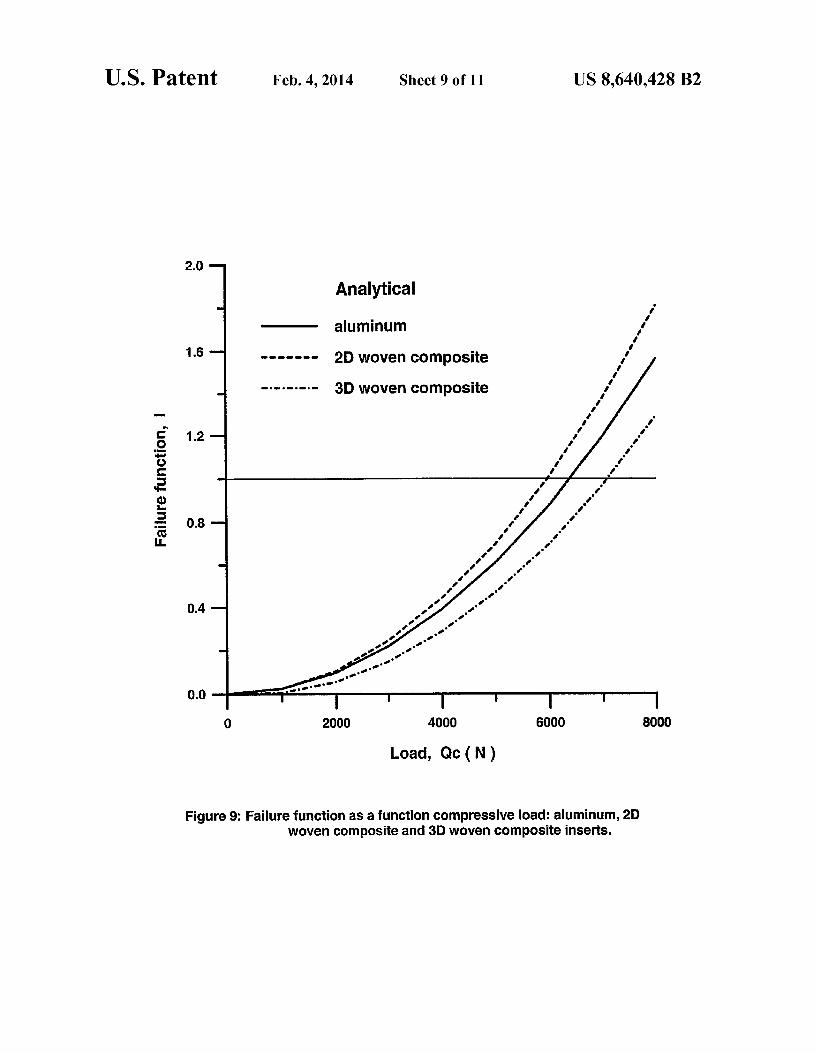
Figure 9: Failure function as a function compressive load: aluminum, 2D woven composite and 3D woven composite inserts.
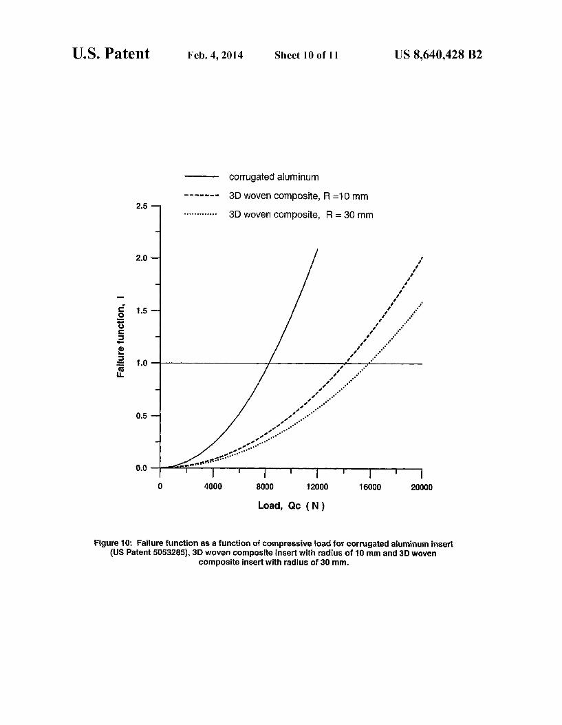
Figure 10: Failure function as a function of compressive load for corrugated aluminum insert (US Patent 5053285), 3D woven composite insert with radius of 10 mm and 3D woven
composite insert with radius of 3D mm.

U.S. Patent Feb. 4, 2014 sheet 11 0f 11 Us 8,640,428 B2
3 . . . .
3D woven composite with multlple mserts
3D functionally gradient woven composite
2 _.J
c“ .Q ‘6' C _ 5 q
E 2 'E
1
0 i | | l
0 5000 10000 15000 20000 25000
Load, Qc (N )
Figure 11: Failure function as a function compressive load for different insert materials.

US 8,640,428 B2 1
STRENGTH ENHANCING INSERT ASSEMBLIES
FIELD OF THE INVENTION
This invention relates to insert assemblies of high specific strength to reduce stress concentrations at locations where multidirectional stresses act on sandwich structures designed based on mapping stress distribution and failure initiation.
BACKGROUND OF THE INVENTION
Light weight sandwich structures are used in structural applications such as vehicles, aerospace industry, framework etc. because of their superior strength and stiffness properties along through-the-thickness direction under bending loads. The use of inserts is essential to strengthen the sandwich structures to withstand localiZed loads. Further, when the external members or sub-structures are attached to sandwich
structures, inserts become a necessity. The specific strength of an insert assembly is a ratio of load
at failure initiation to weight of the insert assembly which should be as high as possible to achieve effective utiliZation of sandwich structures with inserts. In practice, these inserts are made of aluminum alloys, other metals/ alloys etc. High den sity of metals/alloys increases the weight of insert assembly resulting in undesirable reduction in the specific strength. Further, the difference in material properties at the interface between the insert and the potting material such as resin leads to high stress concentration at the interfaces between insert and potting material and between potting material and core.
U.S. Pat. No. 5,240,543 discloses a basic procedure to seat a fastener insert in a honeycomb panel. A fastener insert made of alloy attached to a mounting fixture is inserted into a hole drilled in a honeycomb panel. The mounting fixture has a rod with a disc at an end descending from a base and a chimney ascending from the base. Two bores are located in the base and are enclosed by the chimney. The mounting fixture base overlaps the head ofthe fastener insert which has two bores in the head. The bores in the fastener insert head are aligned with bores in the base of the mounting fixture. Epoxy is inserted into one of the bores in the base of the mounting fixture continuously until it returns out ofthe second bore. The epoxy is allowed to cure and thereafter the mounting fixture is removed by a turning motion. Though this patent describes the method of installation of inserts into honeycomb sand wich structures, it does not address the issue of minimization ofthe insert assembly weight and a means to increase specific strength.
U.S. Pat. No. 5,082,405 and U.S. Pat. No. 4,941,785 dis close the geometry of the inserts and the method to attach the insert to the attachment. In this insert assembly, epoxy resin is used as potting compound. The insert is a metallic member, made of stainless steel, aluminum alloy, and carbon steel. However, a metal insert increases the weight of the insert assembly resulting in reduction of specific strength.
U.S. Pat. No. 5,053,285 discloses the method and appara tus for making corrugated aluminum inserts. These inserts are made from aluminum foil strips by passing the strips through the corrugating device. Though the weight of such inserts is less, stresses at the interfaces of different materials increase because the elastic properties of corrugated aluminum inserts are less resulting in higher stress concentrations.
U.S. Pat. No. 6,055,790 discloses construction ofan insert wherein the conduction and radiation are improved through the inserts. To improve the heat transfer rate, one of the face-plates is made of metal sheet. The insert material is
20
25
30
35
40
45
50
55
60
65
2 aluminum alloy. In this arrangement, a higher thermally con ducting path is provided from one side ofthe insert assembly to the other side. However, these inserts suffer from the defi ciency such that the surrounding potting material made of resin which is not a good conductor of heat that leads to thermal gradient along the radial direction. This causes higher thermal stresses in the sandwich structure. The use of metal for face-plate increases weight of insert assembly thereby decreasing the specific strength.
U.S. Pat. No. 3,271,498 discloses an improved method of installation of inserts. However it does not address the issue of weight of an insert assembly. A method of fabricating a honeycomb core structure with
embedded fastener is disclosed in U.S. Pat. No. 4,716,067. The bonding material is epoxy resin. The method comprises laying down a first nonmetallic synthetic layer, which may be cured or uncured. Bonded to the first nonmetallic synthetic layer is a honeycomb core layer into which one or more flush head fasteners are inserted into holes in the honeycomb core that have an indentation at one end configured to mate with the underside of the head of a flush head fastener. Bonding is accomplished by priming the walls of the honeycomb core layer adjacent the surfaces of the layer, and the fastener, with a suitable primer, preferably before the fastener is installed, and, coating one of the surfaces of the first nonmetallic syn thetic layer with a suitable adhesive before joining the first nonmetallic synthetic layer to the surface of the honeycomb core layer containing the head of the flush head fastener. Thereafter, the cells of the honeycomb core that surround the fastener are filled with a potting material. Then, a second nonmetallic synthetic layer is bonded to the surface of the honeycomb core remote from the surface to which the first nonmetallic synthetic layer is bonded. There are several drawbacks of this method and insert assembly. The fasteners are made of an alloy. The density of the alloys used is more compared to the composites. Significantly high interfacial stresses develop between the alloy insert and the potting resin material. Further, this patent describes the method of instal lation of inserts into honeycomb sandwich structures. It does not address the issue of enhancing the specific strength of insert assemblies. The shortcomings in prior art vis-a vis use of inserts in
sandwich structure are
Use of metal for inserts which leads to decrease in specific strength of the insert assembly.
Though geometry of the inserts and different methods of installation of these inserts into sandwich structures is addressed, the issue of minimization ofthe insert assem bly weight and a means to increase specific strength of insert assembly has not been addressed.
There are no methods of reliably mapping stress distribu tion and prediction of failure initiation in sandwich structures with diverse geometrical configurations.
SUMMARY OF THE INVENTION
The main object ofthe invention is to provide insert assem blies of high specific strength to reduce stress concentrations at locations where multidirectional stresses act on sandwich structures based on mapping stress distribution and failure initiation in sandwich structures.
It is another objective to provide inserts of composite mate rials.
It is yet another object of the invention to reliably map stress distribution in sandwich structures with insert assem blies.

US 8,640,428 B2 3
It is yet another obj ect of the invention to reliably to select diverse geometrical configurations and materials by mapping stress distribution and obtaining failure initiation.
It is yet another obj ect of the invention to provide insert assemblies with through-the-thickness, fully potted and par tially potted geometrical configurations.
It is yet another object of this invention to explore the use of 2D composites 3D thermo elastic isotropic woven composites 3D woven composites 3D woven composites with multiple inserts, 3D functionally gradient woven composites as inserts
and their combination for insert assemblies Thus in accordance, the invention of the insert assembly
comprises of: insert potting material core
lower face-plate upper face-plate attachment
using insert assemblies wherein insert materials are selected from 2D composites 3D thermo elastic isotropic woven composites 3D woven composites 3D woven composites with multiple inserts 3D functionally gradient woven composites as inserts
and their combination for the insert assemblies wherein the diverse geometrical configurations and materials are selected by mapping stress distribution and obtaining failure initia tion.
DETAILED DESCRIPTION OF THE INVENTION
Features and advantages of this invention will become apparent in the following detailed description and preferred embodiments with reference to the accompanying drawings.
FIG. 1 Through-the-thickness inserts FIG. 2 Fully potted inserts FIG. 3 Partially potted inserts FIG. 4 Flow diagram for the analytical formulation proce
dure FIG. 5 Flow diagram for the solution procedure FIG. 6 Graph depicting transverse displacement as a func
tion of compressive load, through-the-thickness aluminum inserts
FIG. 7 Graph depicting transverse displacement as a func tion of compressive load, through-the-thickness 2D woven composite inserts
FIG. 8 Graph depicting transverse displacement as a func tion of compressive load, through-the-thickness 3D woven composite inserts
FIG. 9 Graph depicting failure function as a function of compressive load: aluminum, 2D woven composite and 3D woven composite inserts
FIG. 10 Graph depicting failure function as a function of compressive load for corrugated aluminum insert (U S 5053285), 3D woven composite insert with radius of l0 mm and 3D woven composite insert with radius of 30 mm
FIG. 11 Graph depicting failure function as a function of compressive load for different insert materials
25
30
35
40
45
50
55
60
65
4 GEOMETRICAL CONFIGURATIONS
The geometrical configurations are a) Through-the-thickness insert configuration b) Fully potted insert configuration c) Partially potted insert configuration
a) Through-the-Thickness Insert Configuration FIG. 1 shows a schematic of the through-the-thickness
insert assembly configuration. Insert 10 is cylindrical in shape with flanges 11, 12 that are integral to provide shear resis tance. The inserts are strongly attached with attachment 13 with bonding/threading. The localiZed external loads are applied to sandwich structures through the attachment 13. The insert-attachment assembly is held in sandwich structure by using potting materials 14 as shown in FIG. 1. The potting materials are different types of resins. Reinforcement is added to the resins to increase the stiffness and strength. Upper face-plate 15, lower face-plate 16 and core 17 are the other components of the insert assembly.
In one of the embodiments of through-the-thickness insert assembly configuration, material of insert is 2D composite.
In another embodiment of through-the-thickness insert assembly configuration, material of insert is 3D thermoelastic isotropic woven composite.
In yet another embodiment of through-the-thickness insert assembly configuration, material of insert is 3D woven com posite.
In another embodiment of through-the-thickness insert assembly configuration, material of insert is 3D woven com posite with multiple inserts.
In yet another embodiment of through-the-thickness insert assembly configuration, material of insert is 3D functionally gradient woven composite.
In another embodiment of through-the-thickness insert assembly configuration, material of insert is a combination of the above mentioned. b) Fully Potted Insert Configuration
FIG. 2 shows schematic ofthe fully potted insert assembly configuration. Insert 20 is cylindrical in shape with flanges 21, 22 that are integral to provide shear resistance. The inserts are strongly attached with attachment 23 with bonding/ threading. The localiZed external loads are applied to sand wich structures through the attachment 23. The insert-attach ment assembly is held in sandwich structure by using potting materials 24 as shown in FIG. 2. The potting materials are different types of resins. Reinforcement is added to the resins to increase the stiffness and strength. Upper face-plate 25, lower face-plate 26 and core 27 are the other components of the insert assembly.
In one of the embodiments of fully potted insert assembly configuration, material of insert is 2D composite.
In another embodiment of fully potted insert assembly configuration, material of insert is 3D thermoelastic isotropic woven composite.
In yet another embodiment of fully potted insert assembly configuration, material of insert is 3D woven composite.
In another embodiment of fully potted insert assembly configuration, material of insert is 3D woven composite with multiple inserts.
In yet another embodiment of fully potted insert assembly configuration, material of insert is 3D functionally gradient woven composite.
In another embodiment of fully potted insert assembly configuration, material of insert is a combination ofthe above mentioned.

US 8,640,428 B2 5
c) Partially Potted Insert Configuration FIG. 3 shoWs schematic of the partially potted insert
assembly configuration. lnsert 30 is cylindrical in shape With flanges 31, 32 that are integral to provide shear resistance. The inserts are strongly attached With attachment 33 With bond ing/threading. The localized external loads are applied to sandWich structures through the attachment 33. The insert attachment assembly is held in sandWich structure by using potting materials 34 as shoWn in FIG. 3. The potting materials are different types of resins. Reinforcement is added to the resins to increase the stiffness and strength. Upper face-plate 35, loWer face-plate 36 and core 37 are the other components of the insert assembly.
ln one ofthe embodiments of partially potted insert assem bly configuration, material of insert is 2D composite.
ln another embodiment of partially potted insert assembly configuration, material of insert is 3D thermoelastic isotropic Woven composite.
ln yet another embodiment of partially potted insert assem bly configuration, material of insert is 3D Woven composite.
ln another embodiment of partially potted insert assembly configuration, material of insert is 3D Woven composite With multiple inserts.
ln yet another embodiment of partially potted insert assem bly configuration, material of insert is 3D functionally gradi ent Woven composite.
ln another embodiment of partially potted insert assembly configuration, material of insert is a combination ofthe above mentioned. lnsert Materials
The insert materials are selected from l) 2D Woven composites ll) 3D Woven composites lll) 3D thermoelastic isotropic Woven composites lV) 3D functionally gradient Woven composites V) 3D Woven composite With multiple inserts
l) 2D Composites 2D composites are those in Which only in-plane reinforce
ments are provided. ln laminated composites made of unidi rectional layers, different layers are oriented accordingly to achieve required elastic and strength properties. ln Woven fabric composites, reinforcements are provided along mutu ally perpendicular directions in the same layer by the process of Weaving. Weaving is the process in Which the Woven fabric is formed by interlacing Warp and fills (weft) yarns in regular sequence of under and over. Based on the sequence of placing the yarns under and over, the Woven fabrics are classified into plain, tWill and satin. Specifically, one under and one over sequence is the plain Weave. ll) 3D Woven Composites 3D Woven performs are fully integrated continuous fiber
assembly having multiaxial in-plane and out of plane fiber orientations. ln such preforms, reinforcement is also provided in through-the-thickness direction in addition to planar direc tions. These preforms are made using the process of 3D Weaving. Based on the Weave pattern, the preforms can be orthogonal interlock Woven or angle interlock Woven. Fur ther, it can be classified into through-the-thickness Woven and layer to layer Woven. Using the 3D preforms and resin trans fer molding, 3D composites are made. 3D composites are 3D orthotropic and macrospecically homogeneous materials. Such materials are characterized by 9 elastic properties and 9 strength properties. lll) 3D Thermoelastic lsotropic Woven Composites
F[hese are a class of 3D composites With special character istics. For such materials, elastic and thermal properties are
25
30
35
40
45
50
55
60
65
6 the same along all the directions. ln other Words, such com posites are thermoelastically isotropic. lV) 3D Functionally Gradient Woven Composites 3D functionally gradient Woven composites are the ideal
materials for making inserts. ln a typical insert assembly With single insert material, there is a significant difference in mate rial elastic properties betWeen insert and potting material and potting material and core. Through-the-thickness elastic properties of insert, potting material and core are ofthe order of 40 GPa, 2.5 GPa and 0.31 GPa respectively. This leads to higher stress concentrations at the interfaces betWeen attach ment and insert, insert and potting material, potting material and core. An ideal Way of reducing the stress concentrations and increasing the specific strength is to use a material system for inserts With gradually varying elastic and strength prop erties along the radial direction. Such a material is called functionally gradient. A composite insert made of function ally gradient material has through-the-thickness elastic prop erties nearly matching With that of the attachment along the inner circumference and through-the-thickness elastic prop erties matching With that of potting material along the outer circumference. Consequently, elastic properties of the insert With such a configuration Would be higher along the inner circumference and loWer along the outer circumference and varying radially in a functionally gradient Way. For such insert materials, the stress concentrations at the interfaces Would be minimum leading to higher specific strength. V) 3D Woven Composites With Multiple lnserts
lnserts made of 3D Woven composite With multiple inserts is a class of inserts made of 3D functionally gradient Woven composite. ln this insert, the elastic and strength properties are not varied gradually along the radius from the inner cir cumference to the outer circumference. lnstead, the elastic and strength properties are varied in a stepped manner. This amounts to using multiple inserts instead of a single insert. lf the material properties are varied in three steps, there Would be three different 3D Woven composites. These three different 3D Woven composites are referred as material 1, material 2 and material 3. A Novel Method to Reliably Map Stress Distribution and
Predict Failure lnitiation in Sandwich Structures With lnserts Under Localized Through-the-Thickness Tensile/Compres sive Loading A novel method is described to map stress distribution in
sandWich structures With inserts under localized through-the thickness tensile/ compressive loading. The core is relatively thick and compressible Whereas the face-plates are relatively thin. The core is analyzed using higher-order sandWich plate theory Whereas the face-plates are analyzed using classical plate theory. The behavior ofthe sandWich structure is repre sented using a set of 24 governing differential equations. For the geometry of the insert assembly and the loading condi tions considered the boundary conditions are specified. ln this case, there are 24 boundary conditions. Using the differential equations and the set of 24 boundary conditions, the defor mation behavior and stress state Within the insert assembly are calculated. Specifically, the folloWing quantities are deter mined: transverse displacement of top and bottom face-plates (Wl and W2), transverse shear stress (1,2), mid-plane radial displacement of top face-plate (uml), mid-plane circumfer ential displacement of top face-plate (vO1 1). The novel method to reliably map stress distribution is described in the form of flow diagrams in FIGS. 4 and 5. The input parameters are: geometry of the insert assembly,
elastic properties of different materials used for making the insert assembly and the loading condition.

US 8,640,428 B2 7
This novel method enables to map the following param eters reliably:
transverse and radial displacements of the insert assembly normal and shear stress components throughout the insert
assembly The final governing equations are: The transverse displacement of the core material,
(l)
F[hrough-the-thickness normal stress in the core material,
w1 - u? (2) o'Z = k1 ><z + ><S1
Radial displacement in the core material,
_ 1 + l(?w1]([ z2 +3c]+ (3) '4C-M01 2 Ñ I_Í-Z Í
Trl( C)+l(z2 +C]ÜW2+ C66 Z 2 2 C Z 4 @r
( l )(ÜZTrz + l?Trz Trz + l ÜZTQZ l ÜTQZ]X(Z3 C22 + C3] 2S1 ür2 r ?r r2 r?r?@ r2 [30 3 4 l2
Circumferential displacement in the core material,
(4)
All the Ci]- are stiffness constants and are calculated using elastic properties of the material.
The normal and shear stress distribution Within the entire insert assembly can be obtained using this novel method. The induced stress state can lead to initiation of failure Within insert assembly. lnitiation of failure is characterized using the folloWing through-the-thickness quadratic interaction failure criterion.
Here, oZ?Through-the-thickness normal stress
1,2, 'ceZ?Transverse shear stresses
35
40
50
55
60
65
8 Zt?Through-the-thickness normal strength SU, SeZ?Transverse shear strengths l?Failure function
Failure function, lil indicates initiation of failure. ln the above method the stress distribution is mapped and
failure initiation is obtained in steps comprising Establishing frame of reference for sandwich structures
With inser‘ts Applying equilibrium equations, continuity conditions and
constitutive relations of the core and the face-plates to obtain 24th order partial differential equation consisting of fundamental variables such as Mid-plane radial displacement of upper and loWer face
plates in radial direction, Mid-plane circumferential displacement of upper and
loWer face-plates in circumferential direction, Transverse displacement of upper and loWer face-plates, Derivative of transverse displacement With respect to
radius of insert assembly of upper and loWer face plates,
Derivative of transverse displacement With respect to circumferential direction of upper and loWer face plates and divided by radius of insert assembly,
Bending moment resultant of upper and loWer face plates in radial direction,
TWisting moment resultant in the plane of radial and circumferential coordinates of upper and loWer face plates,
ln-plane normal stress resultant in radial direction of upper and loWer face-plates,
ln-plane normal stress resultant in the plane of radial and circumferential coordinates of upper and loWer face plates,
ln-plane shear stress resultant in the plane of radial and circumferential coordinates of upper and loWer face plates,
Transverse shear stress component of core in the plane of radial and circumferential coordinates,
Shear stress in circumferential direction on a plane per pendicular to through-the-thickness direction in the core,
Derivative of shear stress in circumferential direction on a plane perpendicular to through-the-thickness direc tion in the core With respect to radius of the insert assembly,
Derivative of transverse shear stress component of core in the plane of radial and circumferential coordinates With respect to radius of the insert assembly,
and further to obtain 24 first order coupled eXact differential equations
Applying boundary conditions to the 24 first order coupled eXact differential equations and solving tWo point boundary value problem to obtain stresses (equation 2), displacements (equations l, 3, 4) and failure initiation (equation 5)
Wherein, frame of reference is established based on i. The attachment is infinitely rigid ii. lnsert and potting material are an integral part of the core
for mathematical formulation iii. ln-plane shear stress and in-plane normal stresses are
neglected in the core material iv. Core material is flexible in nature v. Effective shear modulus of the honeycomb core is consid
ered in modeling vi. lnsert assembly is circular in shape vii. lnteraction betWeen tWo adjacent inserts is negligible viii. lnteraction betWeen the insert and the honeycomb core
along the circumference of the insert assembly is negli gible

US 8,640,428 B2 9
ix. Face-plates are homogeneous and isotropic/quasi-isotro p1c
X. Classical plate theory is applicable for the analysis of the face-plates and
wherein, the steps to obtain 24 first order coupled exact dif ferential equations involve
a. Representing the behavior ofthe sandwich structure with an insert assembly using a set of plurality of equations based on equilibrium equations, constitutive relations and continuity conditions
b. Combining the core and face-plate equations to obtain 24th order governing partial differential equation with 24 unknown fundamental variables
c. Rearranging the governing partial differential equation to 24 first order coupled partial differential equations in terms of 24 fundamental variables, their derivatives with respect to circumferential angle and radius using plural ity of equations
d. Eliminating the dependency of derivatives of circumfer ential angle in the 24 first order coupled partial differ ential equations using Fourier expansions to convert them into 24 first order coupled exact differential equa tions
and wherein, stresses, displacements and failure initiation are obtained by i. Specifying 24 boundary conditions with respect to 24 first
order coupled exact differential equations with l2 bound ary conditions at the interface of attachment and insert and remaining at simply supported outer edge of the insert assembly.
ii. Constituting a two point boundary value problem compris ing 24 first order coupled exact differential equations and boundary conditions
iii. Converting two point boundary value problem into a series of initial value problems by dividing the sandwich struc ture into a number of segments along radial direction
iv. Solving the series of initial value problems numerically using multi-segment method of direct integration for 24 fundamental variables at each segment using continuity conditions between two adjacent segments to determine the stresses and displacements throughout the insert assembly for given loading conditions
v. Obtaining the failure initiation within the insert assembly using quadratic failure criterion and the corresponding fail ure initiation load
vi. Obtaining transverse, radial and circumferential displace ments (equations l, 3, 4), through-the-thickness normal (equation 2) and shear stress components in the core, induced normal stress resultants, induced shear stress resultants and induced bending moment resultants in the face-plates and specific strength of the insert assembly based on geometrical, mechanical and physical properties of the insert assembly and loading conditions. The method described above was used to obtain geometri
cal configuration of the inserts and the displacement and failure initiation were predicted and experimentally verified. The present work establishes the superiority of the inserts of the present invention over inserts of prior art.
EXAMPLE l
Experimental Studies
Fabrication of Through-the-Thickness Insert Assembly The insert assembly comprises of six constituents. They
are: insert, potting material, foam core, lower face-plate,
20
25
30
35
40
45
50
55
60
65
10 upper face-plate and the attachment. Lower face-plate and the upper face-plate are made of woven fabric E glass and epoxy resin using matched-die molding technique. The core is made of polyurethane foam. The attachment is made of mild steel. The material used for composite inserts is glass. The potting material is epoxy resin. Three insert assemblies were con
structed using the above with aluminum, 2D woven compos ite and 3D woven composite as insert materials.
Measurement of load, displacements and failure initiation
The insert assembly was placed on a support ring and then located on Hounsfield Test Equipment?450 KS, 50 KN UTM.
Compressive load was applied through the attachment on to the insert assembly.
The displacement of the attachment, lower face-plate, upper face-plate and the corresponding load were measured at loading rate of 0.25 mm/min.
Failure initiation ofthe insert assembly is obtained from sudden change in the load-displacement plot.
Experimental Results Transverse displacement as a function of compressive load
for through-the-thickness inserts is presented in FIGS. 6-8. For the same geometrical configurations and material prop erties (Tables l and 2), analytically obtained transverse dis placement plots, compressive load at failure initiation and specific strength of inserts are presented in FIGS. 6-8 and Tables 3 and 4. The compressive loading was applied until the failure initiation took place.
Failure functions (equation 5) are plotted as a function of compressive load in FIG. 9. It is observed from Tables 3 and 4 that the compressive load at failure is higher for the case of 3D woven composite compared to the aluminum as insert material. The specific strength of insert is significantly higher for the case of 3D woven composite compared to the alumi num insert case. For the case of 2D woven composite insert, it is in between aluminum and 3D woven composite.
TABLE l
Geometrical configuration ofthe insert assembly for the experimental studies.
Diameter mm Thickness mm
Con- Attach- Potting Upper Lower figu- ment, Insert, material, Sup- plate, plate, Core, ration Da Di, Dp port, Dh t1 t2 c
l 5 l0 40 120 2 2 l0
TABLE 2
Material properties of foam core sandwich structure with inserts: used for experimental studies.
Young’s Material modulus, EZ (GPa) Shear modulus, Grz (GPa)
aluminum 70 27 2D woven composite 6 2.5 3D woven composite l0 4.5 Epoxy resin 2.5 0.93 Foam core 0.025 0.009
Face-plate l l0* 4.2* Face-plate 2 l0* 4.2*

US 8,640,428 B2 11 12
TABLE 3
Speciñc strength of through-the-thickness inserts With different materials: eXperimental studies.
Volume ofinsert, V = 1.22 x 10i6 m3 Density of aluminum = 2800 Kg/m3
Density of2D Woven composite = 1700 Kg/m3 Density of3D Woven composite = 1700 Kg/m3
Specific strength of
At failure initiation insert = (MaX. % increase %
Compressive Mass of Compressive in speciñc decrease Sr. load, Displacement, insert, load/Weight strength of in mass of No Insert Qc (N) W (mm) m (Kg) of insert) insert insert
1 Aluminum 5610 5.9 3.416 X 10i3 0.1642 X 10⁶ Reference Reference 2 2D Woven 5420 5.2 2.074 x 10i3 0.2613 x 10⁶ 59.10 39.29
composite 3 3D Woven 5695 7.7 2.074 x 10’3 0.2746 x 10⁶ 67.23 39.29
composite
TABLE 4
Specific strength of through-the-thickness inserts With different materials: analytical predictions for eXperimental configurations.
Volume of insert, V = 1.22 x 10i6 m3 3D Woven composite insert: Zt = 45 MPa, Sr'z = 36 MPa
2D Woven composite insert: Zt = 27 MPa, Sr'z = 36 MPa
Aluminum insert: Zt = 150 MPa SrZ = 30 Mpa
Specific strength ofinsert = (MaX.
At failure initiation compressive % increase in % decrease
Sr. Compressive Displacement, load/Weight of speciñc strength in mass of No. Insert load, Qc (N) W (mm) insert) of insert insert
1 Aluminum 6355 6.1 0.186 x 10⁶ Reference Reference 2 2D Woven 5950 5.4 0.287 X 10⁶ 54.30 39.29
composite 3 3D Woven 7040 7.3 0.339 X 10⁶ 82.25 39.29
composite
40 EXAMPLE 2
Comparison of Through-the-Thickness Inserts of Present Invention With Inserts of Prior Art
Using the method of the present invention, compressive load at failure initiation, failure function and speciñc strength of inserts are mapped for the prior art disclosed in U.S. Pat. No. 5,053,285 (corrugated aluminum insert) and for the insert (3D Woven composite insert) ofthe present invention With the
45
same geometry as used for the prior art (R130 mm). The results are given in FIG. 10 and Table 5. Further, the geometry ofthe insert ofthe present invention Was modiñed (R110 mm) to reduce the insert assembly Weight. With such a modiñed configuration, compressive load at failure initiation, failure function and speciñc strength of inserts are mapped. From FIG. 10 and Table 5, it is established that the inserts of the present invention are having higher speciñc strength com pared to the insert of prior art.
TABLE 5
Speciñc strength of through-the-thickness inserts With corrugated aluminum and 3D Woven composite: analytical studies.
Density of Corrugated aluminum = 459 Kgm3 Density of3D Woven composites = 1700 Kg/m3
Specific strength Compressive load Mass of of insert = (MaX. % increase in at failure initiation, insert, m compressive speciñc strength % decrease in
Insert Qc (KN) (Kg) load/Weight of insert) of insert mass of insert
Corrugated 8.27 0.038 21.62 x 10³ Reference Reference aluminum 3D Woven 15.85 0.065 24.23 x 10³ 12.1 -71.0 composite With radius of 30 mm
3D Woven 14.08 0.0068 206.77 x 10³ 856.6 82.2
composite With radius of 10 mm

US 8,640,428 B2 13
EXAMPLE 3
Analytical Studies With Different Insert Materials
Using the experimentally validated method for mapping of stresses, displacements and failure initiation, the results for aluminum, 2D Woven composite, 3D thermoelastic isotropic Woven composite, 3D Woven composite, 3D Woven compos
ite With multiple inserts and 3D functionally gradient Woven composite are obtained for the geometrical configuration of the insert assembly as given in Table 6. Material properties of the insert assembly are presented in Tables 7 and 8.
. . . 15
Maximum displacement, max1mum normal stress and
maximum shear stress corresponding to maximum compres sive load at failure initiation are presented in Table 9. Specific strength of insert for different materials is also presented in Table 9. Failure function as a function of compressive load for different insert materials is presented in FIG. 11.
Percentage increase in specific strength of insert and per centage decrease in mass of insert for the composite inserts compared to the aluminum insert is presented in Table 9. It is observed that there is significant increase in specific strength and decrease in mass of insert for the composite inserts. The maximum gain is for the case of 3D functionally gradient Woven composite inserts.
25
30
TABLE 6
Geometrical configuration ofthe insert assembly for the analytical studies.
Diameter mm Thickness mm 35
Attach
ment, Da
Lovver
plate, Core, t2 c
Con figu ration
Potting material,
DP
Upper plate,
t1 Ins ert ,
D
1 10 20 50 120 2 2 10 40
TABLE 7
Material properties ofthe insert assembly. Volume of insert, V = 4.006 x 10i6 m3
3D Woven composite insert: Zt = 60 MPa, SrZ = 36 MPa, 2D Woven composite insert: Zt = 27 MPa, SrZ = 36 MPa
Aluminum insert: Zt = 150 MPa, Sr'z = 30 MPa,
3D thermoelastic isotropic Woven composite insert: Zt = 55 MPa, SrZ = 36 MPa
Epoxy: Zt = 38 MPa, Zc = 85 MPa, S = 42 MPa 3D Woven composite With multiple inserts: Zt = 60 > 38 MPa,
SrZ = 36 MPa
3D functionally gradient Woven composite insert: Zt = 55 > 38 MPa, SrZ = 36 MPa
45
50
Young’s modulus, EZ (GPa)
Shear modulus, Material GrZ (GPa)
Aluminum 70 2D Woven composite 9 3D thermoelastic isotropic Woven 37.7 composite 3D Woven composite Insert material 1 37.7 Insert material 2 22.0 Insert material 3 8 3D functionally gradient Woven 37.1-2.5 composite Honeycomb Epoxy resin
27 4 3.71
43
1.5 3.71-0.93
0.310 65 2.5
0.138 0.93
14 TABLE 7-continued
Material properties ofthe insert assembly. Volume of insert,V = 4.006 x 10i6 m3
3D Woven composite insert: Zt = 60 MPa, SrZ = 36 MPa,
2D Woven composite insert: Zt = 27 MPa, Sr'z = 36 MPa
Aluminum insert: Zt = 150 MPa, SrZ = 30 MPa,
3D thermoelastic isotropic Woven composite insert: Zt = 55 MPa, SrZ = 36 MPa
Epoxy: Zt = 38 MPa, Zc = 85 MPa, S = 42 MPa
3D Woven composite With multiple inserts: Zt = 60 > 38 MPa, SrZ = 36 MPa
3D functionally gradient Woven composite insert: Zt = 55 > 38 MPa, SrZ = 36 MPa
Young’s modulus, Shear modulus, Material EZ (GPa) G,Z (GPa)
Face-plate 1 15* 4.5* Face-plate 2 15 * 4.5*
*in-plane properties
Tables 2, 7 and 8 are based on the following references.
3D functionally gradient Woven composite inserts are ana lyZed for the range of properties given in Table 7.
REFERENCES
. Naik, N. K. and E. Sridevi. 2002. An analytical method for thermoelastic analysis of 3D orthogonal interlock Woven composites, Journal of Reinforced Plastics and Compos ites, Vol. 21, pp. 1149-1191.
. Naik N. K. et al. 2001. Stress and failure analysis of 3D orthogonal interlock Woven composites, Journal of Rein forced Plastics and Composites, Vol. 20, pp. 1485-1523.
. Naik, N. K. and V. K. Ganesh. 1996. Failure behavior of plain Weave fabric laminates under on-axis uniaxial tensile loading: II?analytical predictions, Journal of Composite Materials, Vol. 30, pp. 1779-1822.
. Shembekar, P. S. and N. K. Naik. 1992. Elastic behavior of Woven fabric composites: II?laminate analysis, Journal of Composite Materials, Vol. 26, pp. 2226-2246.
. Engineered Materials Handbook, Vol. 1, Composites, 1989, ASM International, Materials Park, Ohio.
TABLE 8
Elastic properties of orthotropic composite inserts (at 0 = 0).
Young’s Shear modulus modulus
Er E9 EZ Gre GrZ GGZ Poisson’s ratio
Material (GPa) (GPa) (GPa) GPa) (GPa) (GPa) Ure UrZ UBZ
3D 37.1 37.5 37.7 3.71 3.71 3.71 0.1110.106 0.106 thermo elastic iso tropic Woven
com
posite 3D 46.7 16.4 43.1 3.57 3.55 3.55 0.088 0.222 0.225 Woven
com
posite


