511435 iav se ex c470 5 - contura · has checked declared performance and issued test report no....
TRANSCRIPT

LE
K
LE
K
C 470
www.contura.eu
GB
NO
DE
SE Monteringsvejledning 2
Istruzioni di montaggio 24
Guide d’installation 49
Installatie instructies 74
Installations-anvisning

GB
PRODUCTProduct type Stove lit with solid biofuels Type designation Contura 470T Manufacturing number See rating plate on the stove Intended area of use Heating of rooms in residential buildings Fuel Wood
MANUFACTURERName NIBE AB / Contura Address Box 134, Skulptörvägen 10 SE-285 23 Markaryd, Sweden
CHECKSAccording to AVCP System 3 European standard EN 13240:2001 / A2:2004 Test institute Rein-Ruhr Feuerstätten Prüfstelle, NB 1625, has checked declared performance and issued test report no. RRF-40 05 932
PERFORMANCE DECLARATIONNo. C470T-CPR-130605-SE-1
DECLARED PERFORMANCE
Essential characteristics Performance Harmonised technicalspecification
Reaction to fire A1 WT
Minimum distance to combustible material 100 mm to rear450 mm to side Other safety distances according to the installation instructions
Risk of falling embers Approved
Emissions from combustion CO 0.12% NOx 25 mg/m3 OGC 84 mg/m3 PM 67 mg/m3
Surface temperatures Approved
Cleaning options Approved
Mechanical durability Approved
Emissions of hazardous substances Approved
Nominal output 7 kW
Efficiency 80%
Flue gas temperature in connector at nominal output
255°C
EN 13240:2001 / A2:2004
The undersigned is responsible for the manufacture and conformity with the declared performance.
Niklas Gunnarsson, Business area manager NIBE STOVES Markaryd, 1st July 2013
GB
List of Contents
Technical details 76
Installation distances to walls and ceiling 77
Air supply 78
Unpacking 79
Fitting the fire-box surrond 80
Fitting the smoke baffle 81
Installing the heat-retaining blocks 81
Top flue connection to a steel chimney 81
Rear flue connection to masonry chimney 85
Fitting the soapstone surround 89
Fitting extra side windows 96
How to use the stove 97
A warm welcome to ConturaA warm welcome to the Contura family. We hope you
will get a great deal of pleasure from your new stove.
As a new owner of a Contura stove, you have secured
a product with timeless design and long service life.
Contura also has a combustion process that is both
environmentally friendly and efficient, for the best heat
production.
Read through these installation instructions carefully
before installation. Read how to best light your stove
in the lighting instructions.
WARNING! The stove becomes very hotDuring operation, certain surfaces of the stove become very hot and can cause burn injury if touched. Also, take heed of the strong heat radiated through the door glass. Placing flammable material closer than the safe distance indicated may cause a fire. Smoulder combustion can cause quick gas ignition with the risk of damage to property and personal injury.
NOTE!Report the installation of a stove to your local authority.The owner of the house is personally responsible for ensuring compliance with the mandatory safety requirements and must have the installation approved by a qualified inspector. Your local chimney sweep must also be informed about the installation as this will affect the routines for regular chimney-sweeping services.
76
GB
LEK
Rökhylla
Rostertallrik
Gjutgodsbotten
Täckbitar
Brasbegränsare
Asklåda
Täljsten/keramik
Eldstadsbeklädnad
Plåtprofiler
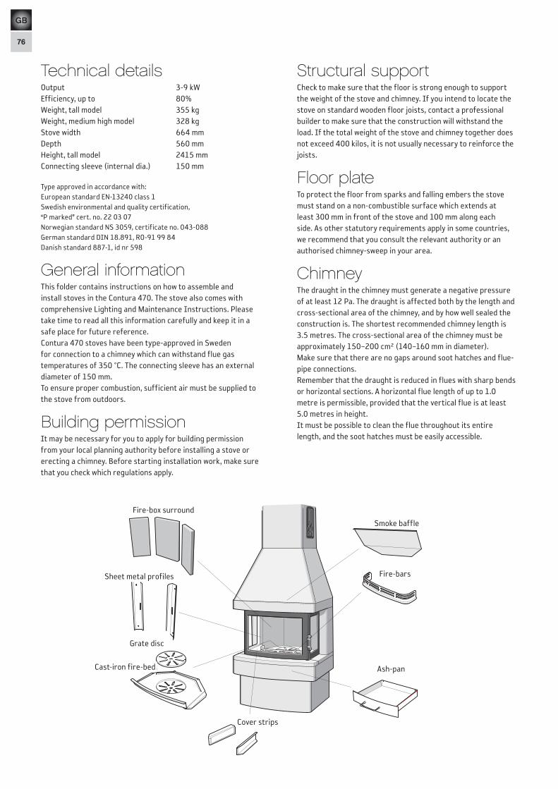
Technical detailsOutput 3-9 kWEfficiency, up to 80%Weight, tall model 355 kgWeight, medium high model 328 kgStove width 664 mmDepth 560 mmHeight, tall model 2415 mmConnecting sleeve (internal dia.) 150 mm
Type approved in accordance with:European standard EN-13240 class 1Swedish environmental and quality certification, “P marked” cert. no. 22 03 07Norwegian standard NS 3059, certificate no. 043-088German standard DIN 18.891, RO-91 99 84Danish standard 887-1, id nr 598
General informationThis folder contains instructions on how to assemble and install stoves in the Contura 470. The stove also comes with comprehensive Lighting and Maintenance Instructions. Please take time to read all this information carefully and keep it in a safe place for future reference. Contura 470 stoves have been type-approved in Sweden for connection to a chimney which can withstand flue gas temperatures of 350 °C. The connecting sleeve has an external diameter of 150 mm.To ensure proper combustion, sufficient air must be supplied to the stove from outdoors.
Building permissionIt may be necessary for you to apply for building permission from your local planning authority before installing a stove or erecting a chimney. Before start ing installation work, make sure that you check which regulations apply.
Structural supportCheck to make sure that the floor is strong enough to support the weight of the stove and chimney. If you intend to locate the stove on standard wooden floor joists, contact a professional builder to make sure that the construction will withstand the load. If the total weight of the stove and chimney together does not exceed 400 kilos, it is not usually necessary to reinforce the joists.
Floor plateTo protect the floor from sparks and falling embers the stove must stand on a non-combustible surface which extends at least 300 mm in front of the stove and 100 mm along each side. As other statutory requirements apply in some countries, we recommend that you consult the relevant authority or an authorised chimney-sweep in your area.
ChimneyThe draught in the chimney must generate a neg ative pressure of at least 12 Pa. The draught is affected both by the length and cross-sectional area of the chimney, and by how well sealed the construction is. The shortest recommended chimney length is 3.5 metres. The cross-sectional area of the chimney must be approximately 150–200 cm² (140–160 mm in diameter). Make sure that there are no gaps around soot hatch es and flue-pipe connections. Remember that the draught is reduced in flues with sharp bends or horizontal sections. A horizontal flue length of up to 1.0 metre is permissible, provided that the vertical flue is at least 5.0 metres in height. It must be possible to clean the flue throughout its entire length, and the soot hatches must be easily accessible.
Fire-bars
Ash-pan
Smoke baffle
Grate disc
Cast-iron fire-bed
Cover strips
Fire-box surround
Sheet metal profiles
292 292
664
340
1050
1600
Air inlet Ø64
Tall
mod
el
2415
Min
. 210
0 to
cei
ling

77
GB
Stand the stove on a floor plate which meets the requirements laid down on page 76. Measure to make sure that the size of the floor plate and the distance between the stove and the wall are at least as great as specified in the diagrams below. Allow at least 1.0 metre from the stove door to any combustible part of the building structure or interior fittings.
Important!
When placing the stove in a corner close to combustible wall materials or against a wall with a gap of only 305 mm to combustible materials, an extra side window with a heat-reflecting surface must always be fitted.
365
100
250
450*305
782*637
Air inlet Ø64
Combustible wall
* Only permissible with extra side window. Please see page 96.
370
1190
360
1050
407
40
520
560
265
340
ca
1790
940
ca
1610
Air inlet Ø64
Combustible roof
Med
ium
hig
h m
odel
205
0
349
432
282
50
50
845
Air inlet Ø64
Fire-retardant wall ofbrick or concrete
292 292
664
340
1050
1600
Air inlet Ø64
Tall
mod
el
2415
Min
. 210
0 to
cei
ling
*100
539
622
240
240
*399
*482
*100
1035*895
Air inlet Ø64
Combustible wall
Installation distances to walls and ceiling
50
105
5020
0382
Air inlet Ø64
Fire-retardant wall ofbrick or concrete
Fire-retardant wall of brick or concrete
Fire-retardant wall of brick or concrete
78
GB
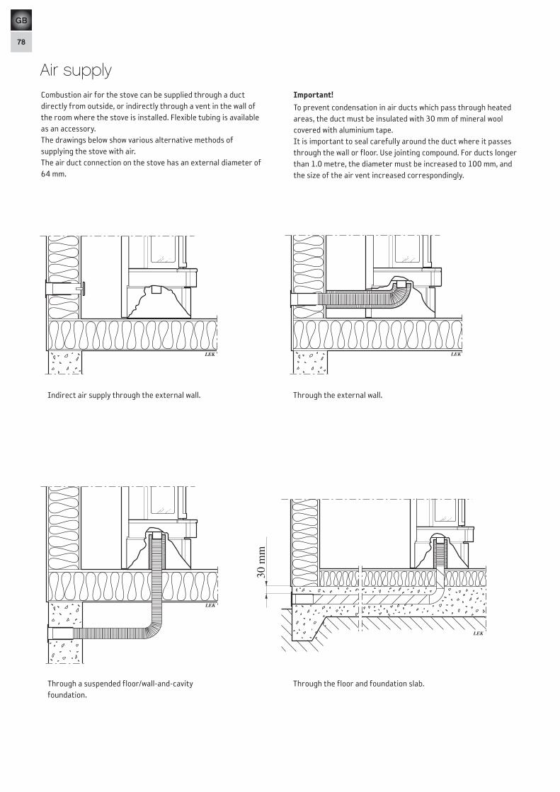
Combustion air for the stove can be supplied through a duct directly from outside, or indirectly through a vent in the wall of the room where the stove is installed. Flexible tubing is available as an accessory.The drawings below show various alternative methods of supplying the stove with air.The air duct connection on the stove has an external diameter of 64 mm.
Important!
To prevent condensation in air ducts which pass through heated areas, the duct must be insulated with 30 mm of mineral wool covered with aluminium tape.It is important to seal carefully around the duct where it passes through the wall or floor. Use jointing compound. For ducts longer than 1.0 metre, the diameter must be increased to 100 mm, and the size of the air vent increased correspondingly.
Through the external wall.Indirect air supply through the external wall.
LEK
Through the floor and foundation slab.Through a suspended floor/wall-and-cavityfoundation.
LEK
LEK
LEK
30 m
m
Air supply

79
GB
LEK
LE
K
Lift and transport the stove as shown in these sketches.The cast-iron door and fire-bed may be removed to
make the stove lighter and easier to move.
Remove the cast-iron cover strips below the side windows.
LEK
LEK
Remove the grate disc by lifting the edge furthest away from the draught control bar.
Lift the cast-iron fire-bed at one side and tilt it so that it can be removed through the door opening.
LEK
LEK
Unscrew the metal brackets from the rear edge of the side windows.
Unpacking

80
GB
Fitting the fire-box surrond
LEK
LEK
LEK
Vermiculitehållare
LEK
Remove the cast-iron cover strips below the side windows. Unscrew the metal brackets from the rear edge of the side windows.
Slot the two front fire-bricks. Screw the retaining brackets back into place and replace the cover strips.
Fit the rear fire-brick.
LEK
Lift the door upwards until it disengages from the lower hinge.
LEK
Vermiculite holder
Ease the bottom of the door slightly sideways until it clears the hinge pin.

81
GB
LEK
Stödtapp, sida Vermiculitehållare
LE
K
IMPORTANT!
When correctly placed on top of the supporting pegs, the baffle slopes upwards from the back to the front.
Installing the heat-retaining blocksPlace the five olivine blocks on top of the fire-box as shown.
LE
K
When connecting the stove to a steel chimney, always refer to the installation instructions supplied by the chimney manufacturer. The size of the hole in the ceiling through which the chimney passes must be adapted to the dimensions of the chimney shaft itself and to the mandatory “safe distances” to combustible materials in each individual instance. The sketches below show the required
gap between the chimney and any combustible material. The stove can support a maximum chimney weight of 250 kilos. However, we strongly recommend that you check with the building and planning department of your local authority to make sure that local building regulations permit a steel chimney to rest on a stove.
380
380
380380440
440
380
380
380380440
440
When the ceiling is flat, the hole in the ceiling must measure 380x380 mm in size and be cut so that it emulates the angle of the stove, both for installations against a straight wall and in corners.
When the ceiling slopes and the stove is placed in a corner, the hole in the ceiling must measure 440x440 mm in size and be cut parallel to the walls.
Sloping ceiling in corners Flat ceiling
380
380
380380440
440
Vermiculite- holder
Side peg
Top flue connection to steel chimney
Raise the folded front edge of the smoke baffle up over the side pegs. Then lift the rear edge of the baffle up over the vermiculite holder.
Fitting the smoke baffle

82
GB
Bend the four metal lugs on the top edge of the lower section of the chimney frame inwards and upwards. Then screw the upper section in place.
LEK
180°
LEK
Övre skorstensram
Nedre skorstensram
LEK
Startrör
Avtätningsplåt
Isoleringsskiva
Övre startrör
Stoppbricka
Övergångsisolering
Skorstensmodul
Check to ensure that the stove-body is standing straight and perpendicular. Slide the flue base over the collar. Make sure that the seal round the collar is not dislodged. If further sealing material is required, heat-resistant sealant may be used.
When using a Premodul chimney system, attach the sealing plate and insulating panel to the start pipe. Cut out the knockout from the sealing plate and fold the four tabs down slightly. Move the upper start pipe down through the sealing plate with all four tabs trailing against the outside of the pipe. Insert the upper start pipe down in the start pipe and check that the four tabs are against the outside of the upper start pipe and on the upper edge of the start pipe (see enlarged image). Install the insulating panel, stop washer, transitional insulation and chimney module.
For different chimney systems, the sealing plate can be screwed to the rear panel and the insulating panel laid on top.
Chimney frame - upper section
Chimney frame - lower section
Chimney module
Stop washer
Insulating panel
Upper start pipe
Sealing plate
Start pipe
Transitional insulation

83
GB
Bend up the fixing lugs on the supporting structure and screw the chimney frame into place on the structure.
LEK
90°
LEK
LEK
LEK
Hål i innertak90°
Poke the corners of the block of insulating material out through the holes in the corners of the chimney frame. Screw the back-panel of the chimney onto the chimney frame. Make sure the back panel of the chimney fits inside the back panel on the stove body.
LEK
Hole in ceiling
84
GB
LE
K
LEK
LEK
90ϒ LE
K
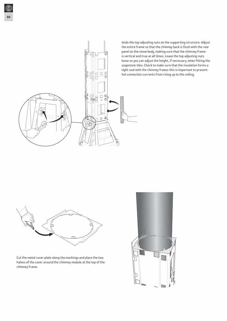
Cut the metal cover plate along the markings and place the two halves of the cover around the chimney module at the top of the chimney frame.
Undo the top adjusting nuts on the supporting structure. Adjust the entire frame so that the chimney back is flush with the rear panel on the stove body, making sure that the chimney frame is vertical and true at all times. Leave the top adjusting nuts loose so you can adjust the height, if necessary, when fitting the soapstone tiles. Check to make sure that the insulation forms a tight seal with the chimney frame: this is important to prevent hot convection currents from rising up to the ceiling.

85
GB
Slide the connecting flue over the collar. Make sure that the seal round the collar is not dislodged.
Cut away the inner and outer marked cover on the rear panel of the stove body.
LE
K
Brytlock
LE
K
Täcklock
LEK
LEK
Gäller ej!
Use sealing rope for a safe seal between the flue sleeve and the connecting flue. If further sealing material is required, heat-resistant sealant may be used.
LE
K
The stove is supplied ready for connection to a top flue. For rear-flue connections the covering cap and collar need to exchange places.
Loosen the top adjusting nuts for the support structure. Adjust the support structure to ensure that it is perfectly horizontal.Leave the top adjusting nuts loose in order to make any necessary adjustments to the height when installing the soapstone blocks.
LE
K
Mark out the centre of the hole to be made in the wall for a rear flue connection. Make a hole at least 180 mm in diameter and then secure the flue sleeve in the wall using heat-proof mortar (not supplied).
Check the height to make sure that the hole aligns with the chimney connection on the rear of the stove. Leave the mortar to dry before connecting the stove to the flue.
Low model, flue height 940 mm
Covering cap for flue
Partly punched cover
Rear flue connection to masonry chimney
86
GB
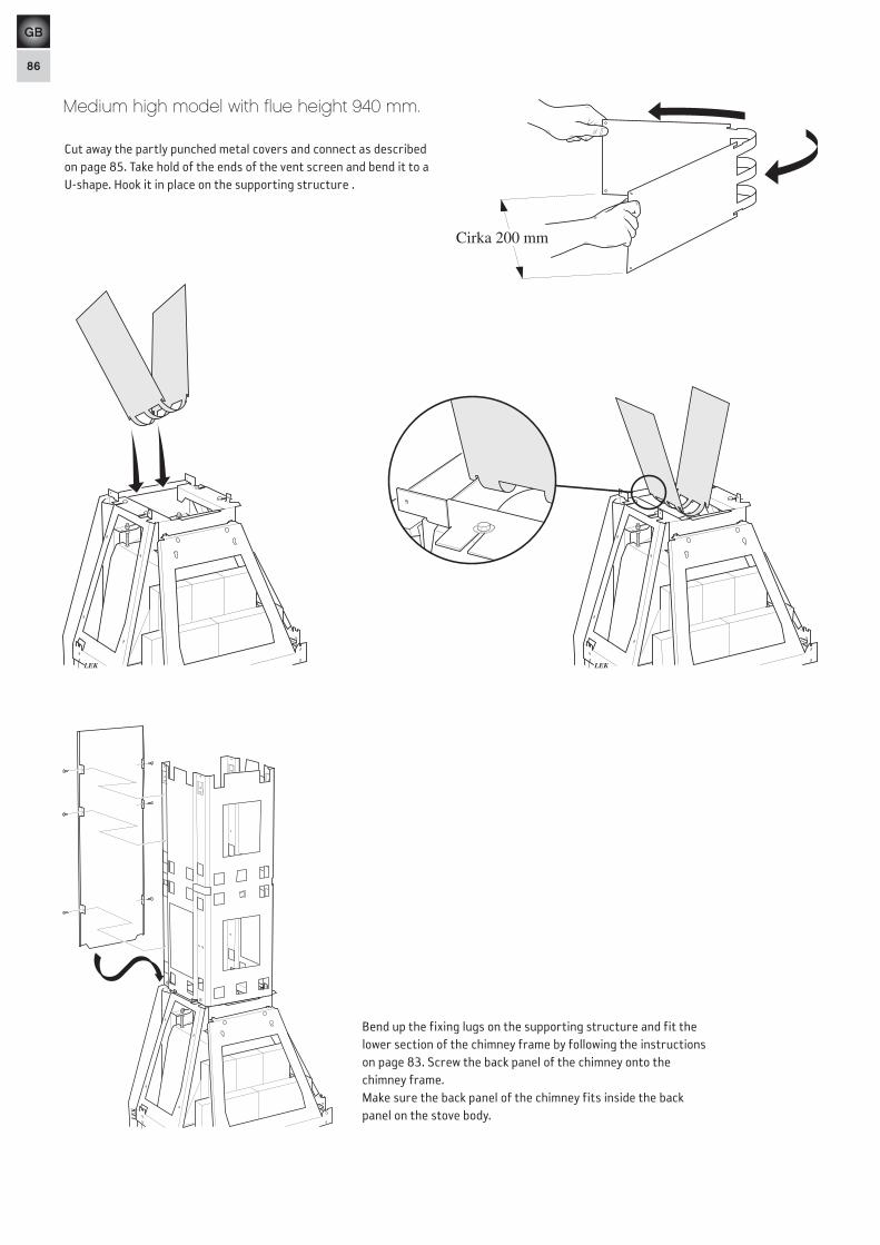
Cut away the partly punched metal covers and connect as described on page 85. Take hold of the ends of the vent screen and bend it to a U-shape. Hook it in place on the supporting structure .
LEK
Cirka 200 mm
LEK LEK
Bend up the fixing lugs on the supporting structure and fit the lower section of the chimney frame by following the instructions on page 83. Screw the back panel of the chimney onto the chimney frame.Make sure the back panel of the chimney fits inside the back panel on the stove body.L
EK
Medium high model with flue height 940 mm.
87
GB
LE
K
90 °
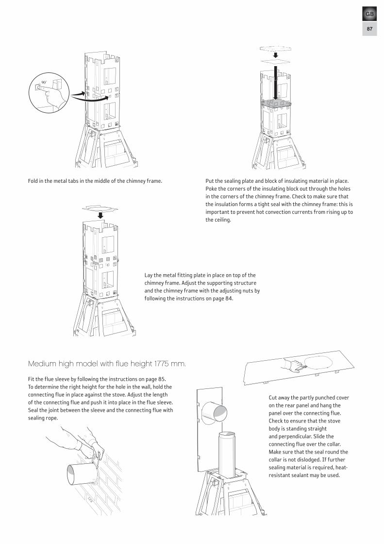
Lay the metal fitting plate in place on top of the chimney frame. Adjust the supporting structure and the chimney frame with the adjusting nuts by following the instructions on page 84.
Medium high model with flue height 1775 mm.
Fold in the metal tabs in the middle of the chimney frame.
LE
K
LE
K
Put the sealing plate and block of insulating material in place. Poke the corners of the insulating block out through the holes in the corners of the chimney frame. Check to make sure that the insulation forms a tight seal with the chimney frame: this is important to prevent hot convection currents from rising up to the ceiling.
LEK
LEK
LEK
Gäller ej!
Fit the flue sleeve by following the instructions on page 85. To determine the right height for the hole in the wall, hold the connecting flue in place against the stove. Adjust the length of the connecting flue and push it into place in the flue sleeve. Seal the joint between the sleeve and the connecting flue with sealing rope.
LE
K
Cut away the partly punched cover on the rear panel and hang the panel over the connecting flue.Check to ensure that the stove body is standing straight and perpendicular. Slide the connecting flue over the collar. Make sure that the seal round the collar is not dislodged. If further sealing material is required, heat-resistant sealant may be used.

88
GB
Bend up the fixing lugs on the supporting structure and fold in the metal tabs in the middle of the chimney frame as described in the instructions on pages 83 and 87. Hold the sealing plate and fit the chimney frame into place, ensuring that the sealing plate and insulation block are resting on the metal tabs. Secure the chimney frame by screwing into the fixing lugs on the supporting structure, and then poke the corners of the insulating block out through the holes in the corners of the chimney frame.Screw the back panel of the chimney onto the chimney frame. Adjust the entire chiimney frame with the adjusting nuts by following the instructions on page 84. Check to make sure that the insulation forms a tight seal with the chimney frame and the connecting flue: this is important to prevent hot convection currents from rising up to the ceiling. Lay the fitting plate in place on top of the chimney frame (see picture page 87).
Important!If you connect the stove to a rear flue, but wish to install an extra layer of soapstone tiles reaching right up to a ceiling made of combustible material, please note the following:• This is a special, customised solution, so the extra layer of chimney tiles and the chimney frame will have to be cut to size on site.• The elbow joint must be insulated with an extra 60 mm of mineral wool (not supplied.)• To ensure the right ventilation, there must be a gap of at least 200 mm between the ceiling and the top of the rear panel of the chimney
(the top section of the rear panel must be removed, or cut to size on site).• There must be a gap of at least 5 mm between the soapstone tiles and the ceiling to allow for an expansion in the length of the chimney
during heating.
LE
K
Cut away the partly punched metal cover and slide the sealing plate and the block of insulating material down into place around the connecting flue.
LE
K
Pannkitt
Spread sealant over all joints. Fit the elbow joint in place and slide it into the connecting flue.
Heat-resistant sealant

89
GB
Sockelfront 003692
Sockelsida 003691
Frissida 003693
Vänster fristopp003695
Pelare 003697
Kåpsidobas003698
Vänster kåpsida003700
Skorstenssida med varmluftshål 003705
Skorstenssida003702
Vänster & högerskorstenstopp003706
Frisfront 003694
Främre fristopp003696
Höger fristopp 003690
Kåpfrontbas 003699
Kåpfront 003701
Höger kåpsida003704
Skorstensfront003703
Främre skorstenstopp003707
Each tile is assigned a name and number, according to the scheme illustrated below. Certain tiles can be used in more than one position and therefore have the same number. We recommend that the tiles are fitted in the order described on the following pages.
Important!
Handle soapstone with care. The tiles scratch easily and may be marked by oil and grease.
Left & right chimney coping 003706
Chimney side 003702
Chimney side with air vent 003705
Left-hand hood 003700
Left-hand border top 003695
Border side 003693
Plinth side 003691
Front chimney coping 003707
Chimney front 003703
Right-hand hood 003704
Hood front 003701
Plinth front 003692
Left-hand hood base 003698
Pillar 003697
Hood-front base 003699
Right-hand border top 003690
Front border top 003696
Border front 003694
Fitting the soapstone surround

90
GB
LEK
Fit the left and right-hand hood bases with hexagon screws so that they align with the hood-front base. Make sure that the right and left-hand hood bases are horizontal (same height back and front).
LEK
Justerskruv
LEK
Justerskruv
105
LEK
20
12
67
8
40
30
1615
1413
1211
109
LEKLEK
72
20
12
67
8
40
30
1615
1413
1211
109
Adjust so that there is a 72 mm gap between the hood bases and the stove body.
Fit a stud bolt to the hood-front base and secure it.
The top of the tile should be flush with the edge of the metal by the screws. Adjust so that there is a 105 mm gap between the hood-front base and the stove frame.
Adjustment screw
Adjustment screw

91
GB
LEKLEK
383 10
LEKLEK
Silicone
Adjust the height of the entire hood by turning all of the adjusting nuts on the supporting structure by the same amount. When making the adjustment, all the locknuts on the top must be loose with a certain amount of play. Adjust the measurement so that the height between the bottom edge of the left and right-hand hood sides and the top edge of the guides is 383 mm on both
sides. Make sure that the measurements on page 90 are correctly adjusted and check them in accordance with the instructions on page 84. Tighten the locknuts on the top. There may be slight variations between the sides if the chimney frame is not exactly perpendicular. There should be a 10 mm gap between the top of the door and the hood-front base.
LEK
Squeeze two blobs of silicone onto the bottom half of the metal hood seats and put the hood’s side tiles in place.It is also possible to remove the hood seats with the tiles on and fit nuts to the stud bolts for added security. When the hood seats are put back in place, it is important that they are pushed into the bottom of the groove. Note that the washers should normally be on the top of the metal, but can be fitted to the underside if the hood seats need to be lowered individually.
Screw two stud bolts into each of the hood’s side tiles.

92
GB
LEK
Squeeze two blobs of silicone onto the bottom half of the metal hood seat and put the hood front in place.
Unscrew the angle-irons from the guides and screw them in place on the side tiles of the border. Fit the border sides in place with the help of the angle-irons.
LEKLEK
Lay the tiles that form the top of the border (left, front and right) in place, leaving a small gap of about 3 mm to the stove body. Check to make sure that they fit flush with the tiles that form the sides of the border. Adjust the side-tiles if necessary.
LEKLEK
Silicone
Screw two stud bolts into the hood front.
LEKLEK
3 mm
Montage-skruvarAssembly screws

93
GB
Silicone
Release the springs from the guide arms and fold down the metal frame for the border tiles.
LEKLEK
LEK
Screw the short stud bolts into the tile that forms the front of the border and squeeze out five small vertical beads of silicone onto the back of the tile. Screw the tile to the border frame.
LEK
0,5 - 1 mm
0,5 - 1 mmLEK
Undo the screws between the border frame and the guide arms. Adjust the border frame and the front border tile to allow about 0.5–1 mm clearance between the sides of the border and the front border top when the guide arms are fully pushed in.

94
GB
LEKLEK
Silicone
Glue the top tiles in the border to the stove body.
LEK
Place the pillars on the border top and ease them into place so that they clip over the metal tab in the hood seat. To protect the border top, place a piece of paper between the pillar and the top tiles in the border when moving the pillar into place. Glue into place with a bead of silicone between the top of the border and the pillar.
Papper
Pl ttunga
LEK
Silicone
Fit four clips to each chimney side and the chimney front. Note that the fixing holes are not symmetrically placed on the sides of the chimney but closer to the rear of the stove.
Screw a metal clip into the top hole on both pillars.
LEK LEK
Hook the springs on the guide arms. If they have come loose from their mounting on the inside, start by hooking them into place there. Hold the spring so that innermost loop is perfectly vertical. Move the spring in towards the hook, keeping the spring
supported by the body of the stove to the side and top. Test to make sure that the spring has hooked in place. Then extend it and fix it to the border frame.
Paper
Metal tab
95
GB
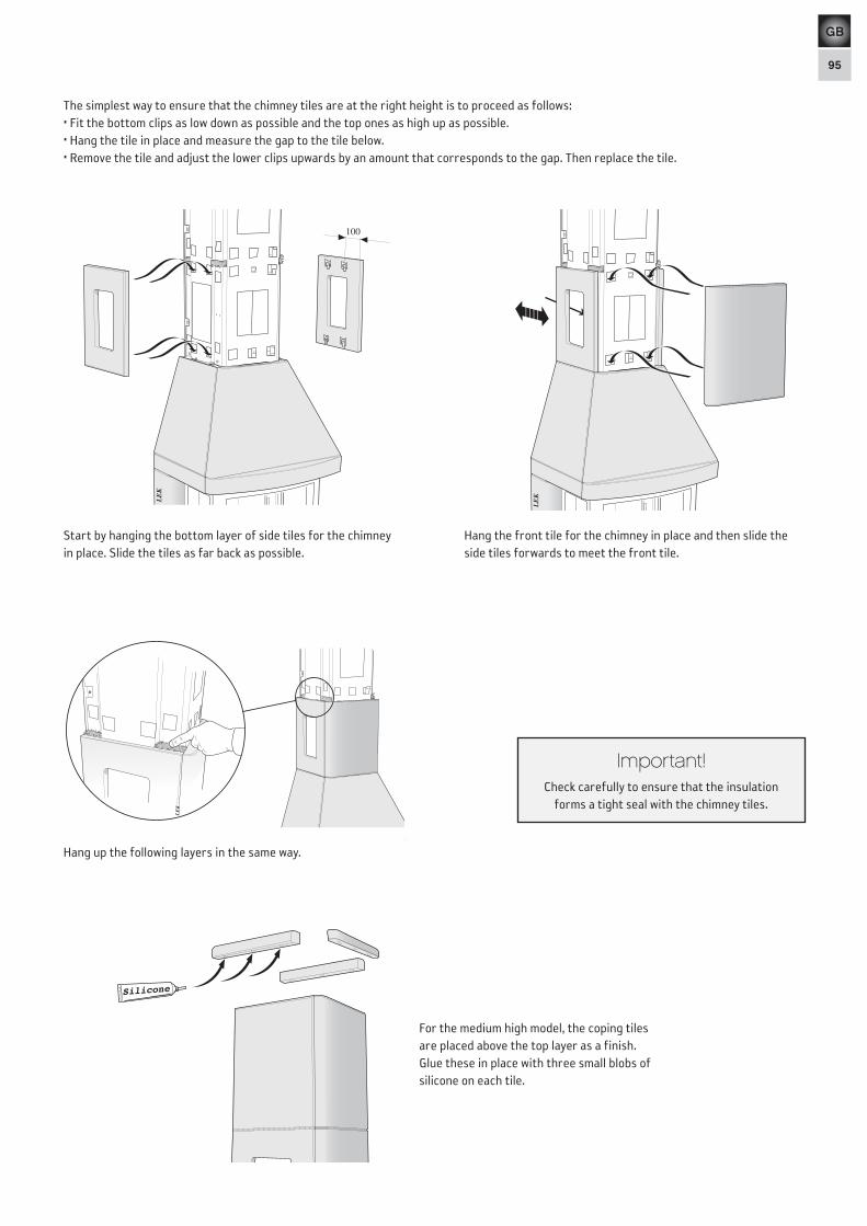
The simplest way to ensure that the chimney tiles are at the right height is to proceed as follows:• Fit the bottom clips as low down as possible and the top ones as high up as possible.• Hang the tile in place and measure the gap to the tile below.• Remove the tile and adjust the lower clips upwards by an amount that corresponds to the gap. Then replace the tile.
Silicone
LEK
LE
K
LE
K
100
Hang up the following layers in the same way.
For the medium high model, the coping tiles are placed above the top layer as a finish. Glue these in place with three small blobs of silicone on each tile.
Hang the front tile for the chimney in place and then slide the side tiles forwards to meet the front tile.
Start by hanging the bottom layer of side tiles for the chimney in place. Slide the tiles as far back as possible.
Important!Check carefully to ensure that the insulation
forms a tight seal with the chimney tiles.
LE
K

96
GB
Hook the retaining brackets for the extra windows into place on the stove body at the top and bottom of the side window.
LEKLEK LEK
Fitting extra side windows
Slide the extra glass into place flush against the rear panel.
LEK
LEK
Silicone
Fit the air vent grilles in place by squeezing out two large blobs of silicone on the side of each hole and pressing the grille into place.
Secure the magnets to the plinth front with screws and plugs. Put the small metal plates on the magnets and stand the plinth front and plinth sides round the fire-box.
LEK
Remove the sides and squeeze out a little silicone onto the metal plates. Then replace the plinth sides.

97
GB
Under normal conditions we recommend that the stove burns 2 kg of wood per hour. The maximum permissible amount is 3.5 kg per hour. Most types of wood can be used: deciduous (broad-leaf) woods are preferable, as they generally burn more calmly. It is important that the wood is dry and that logs are of a suitable size: about 25–35 cm long and 7–9 cm in diameter. Always open and close the door slowly and carefully to prevent the sudden changes in pressure inside the stove which otherwise can cause a back-draught of smoke in the room.1. Open the air supply control by moving the damper spindle to the
right.2. Place newspaper or a firelighter in the fire-box. Then stack
about 3–3.5 kg of fine-split logs on the fire-bed, laid in a criss-cross pattern as shown.
3. Light the fire.4. Push the door to, but do not close it until the fire is burning well
(after about 10–15 minutes).5. When the first pile of logs has burnt down, stoke up the fire
again by placing 3 or 4 logs (weighing 2–2.5 kg in all) on the embers.
Pulling out the damper bar opens the grate disc. This should only be done for a short time when lighting or re-stoking the fire to ensure that the wood catches light quickly, and when riddling the ash into the ash pan. If the grate is left open for a long time, the stove and the chimney may be damaged as a result of the excessive heat.
Important!
It is essential that the wood starts to burn quickly. Smouldering produces excessive amounts of smoke and may, in exceptional circumstances, cause the fumes produced to ignite spontaneously and damage the stove. You can get the logs to burn quickly by opening the grate disc for a short while after re-stoking the fire, or by leaving the door ajar until the wood is burning.
Important!Please read the separate Lighting and Maintenance Instructions carefully before lighting the stove for
the first time.
LEK
ÖPPET
ÖPPET
Roster
Förbränningsluft
Illus
trat
ions
: Lar
s-E
rik K
arls
son
2000
-09-
01
Air supply
Grate
OPEN
OPEN
How to use the stove


NIBE AB · Box 134 · SE-285 23 Markaryd · Swedenwww.contura.eu
Contura reserves the right to change dimensions and procedures described in these instructions at any time without special notice. The current edition can be downloaded from www.contura.eu
511435 IAV SE- EX C470 - 52014-01-27