5. scintillation counters - physikalisches institut heidelbergfschney/detektoren/detektoren... ·...
TRANSCRIPT
5. Scintillation counters
to detect radiation by means of scintillation is among oldest methods of particle detection historical example: particle impinging on ZnS screen -> emission of light flashprinciple of scintillation counter: dE/dx is converted into visible light and transmitted to an optical receiversensitivity of human eye quite good: 15 photons in the correct wavelength range within time interval of 0.1 s noticable by human
scintillating materials: - inorganic crystals - organic crystals - polymers (plastic scintillators)
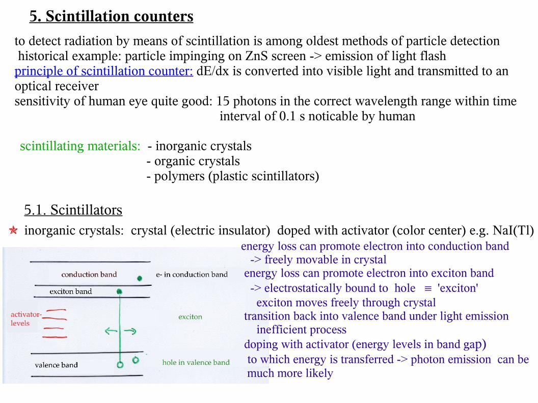
5.1. Scintillators inorganic crystals: crystal (electric insulator) doped with activator (color center) e.g. NaI(Tl)
energy loss can promote electron into conduction band -> freely movable in crystal energy loss can promote electron into exciton band -> electrostatically bound to hole 'exciton' exciton moves freely through crystal transition back into valence band under light emission inefficient process doping with activator (energy levels in band gap) to which energy is transferred -> photon emission can be much more likely
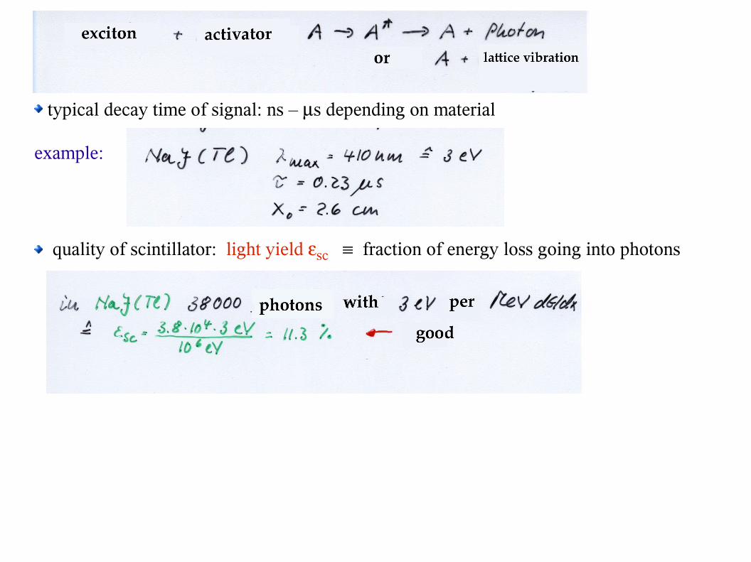
typical decay time of signal: ns – s depending on material
example:
quality of scintillator: light yield sc fraction of energy loss going into photons
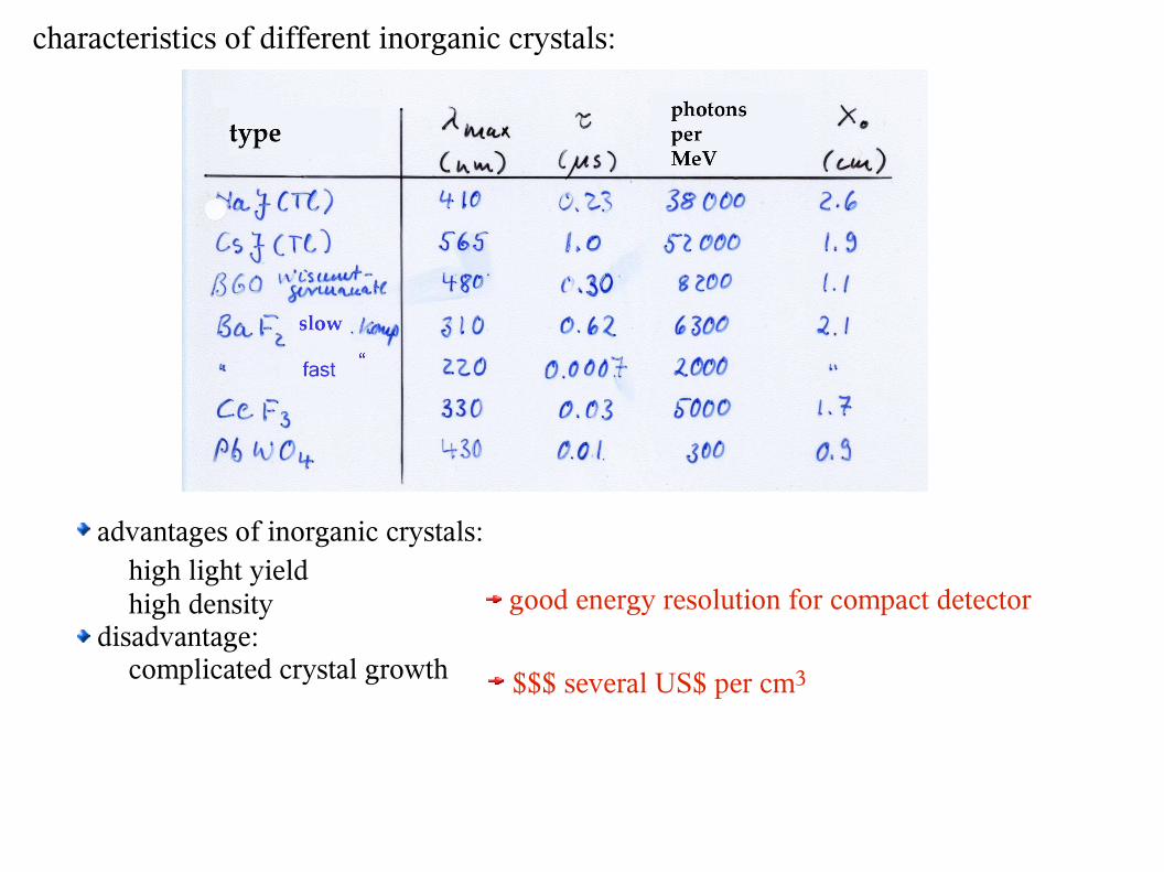
characteristics of different inorganic crystals:
advantages of inorganic crystals: high light yield high density disadvantage:
complicated crystal growth
good energy resolution for compact detector
$$$ several US$ per cm3
crystalsdepth
read-outnoise
dyn. range
gain=1
crystals
read-out gain =noise
dyn. range
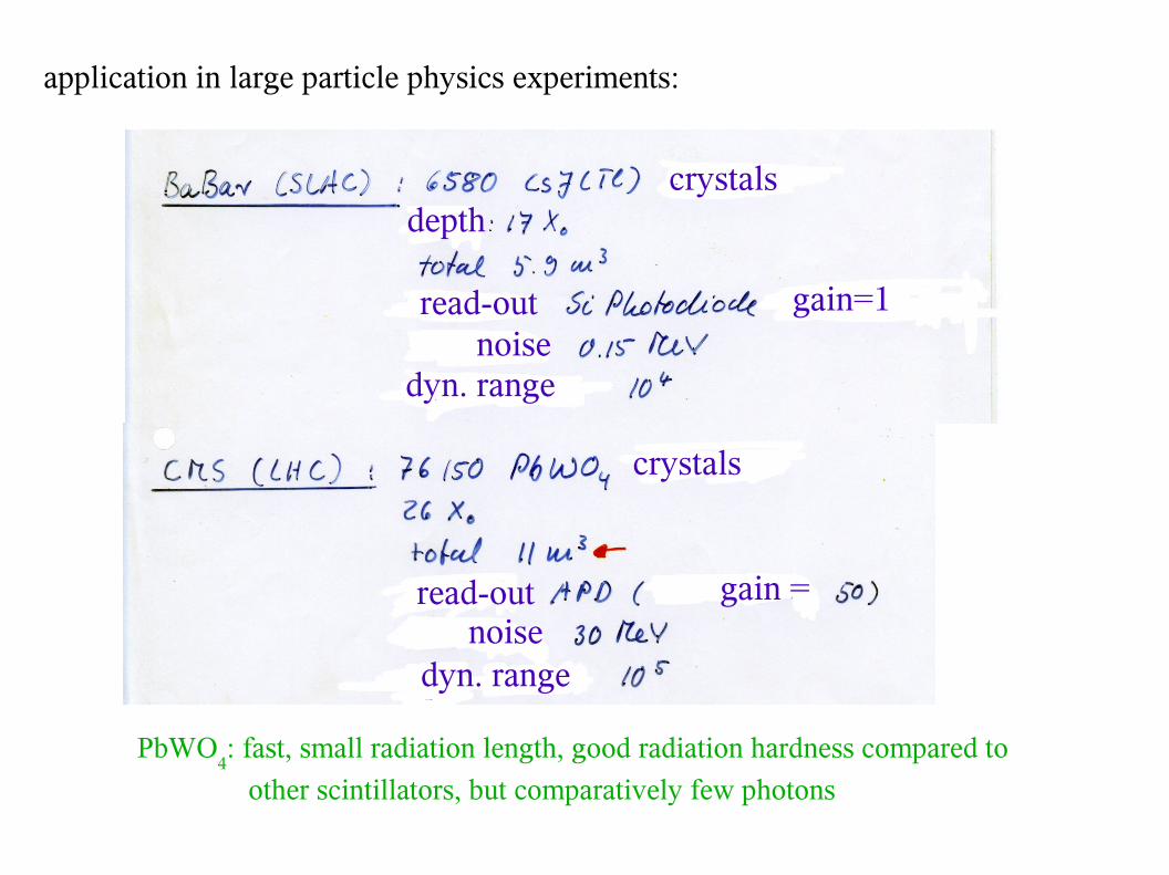
application in large particle physics experiments:
PbWO4: fast, small radiation length, good radiation hardness compared to
other scintillators, but comparatively few photons
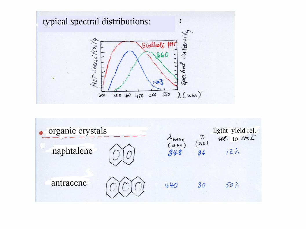
typical spectral distributions:
organic crystals ligtht yield rel.to
naphtalene
antracene
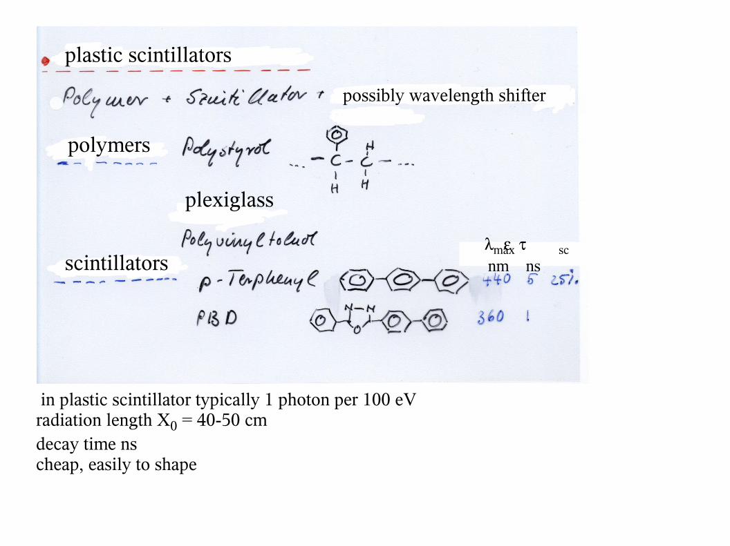
plastic scintillators
possibly wavelength shifter
polymers
plexiglass
scintillatorsmax sc
nm ns
in plastic scintillator typically 1 photon per 100 eVradiation length X0 = 40-50 cmdecay time nscheap, easily to shape
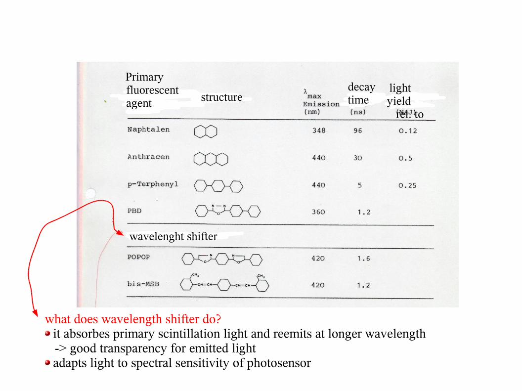
Primary fluorescent agent structure
decaytime
light yield rel. to
wavelenght shifter
what does wavelength shifter do? it absorbes primary scintillation light and reemits at longer wavelength
-> good transparency for emitted light adapts light to spectral sensitivity of photosensor
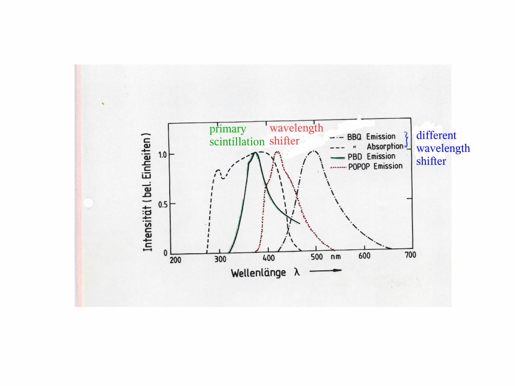
primary scintillation
wavelength shifter different
wavelengthshifter
triplet
states phosphorescence
fluorescence
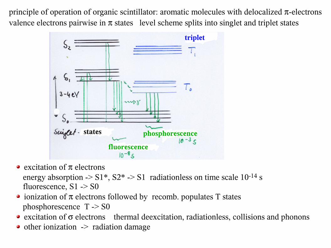
principle of operation of organic scintillator: aromatic molecules with delocalized -electronsvalence electrons pairwise in states level scheme splits into singlet and triplet states
excitation of electrons energy absorption -> S1*, S2* -> S1 radiationless on time scale 10-14 s fluorescence, S1 -> S0 ionization of electrons followed by recomb. populates T states
phosphorescence T -> S0 excitation of electrons thermal deexcitation, radiationless, collisions and phonons other ionization -> radiation damage
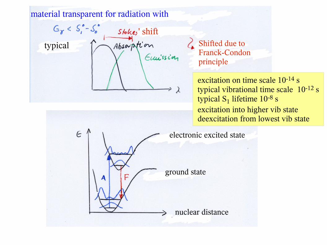
material transparent for radiation with
' shiftShifted due to Franck-Condonprinciple
typical
electronic excited state
ground state
nuclear distance
excitation on time scale 10-14 s typical vibrational time scale 10-12 stypical S1 lifetime 10-8 sexcitation into higher vib statedeexcitation from lowest vib state
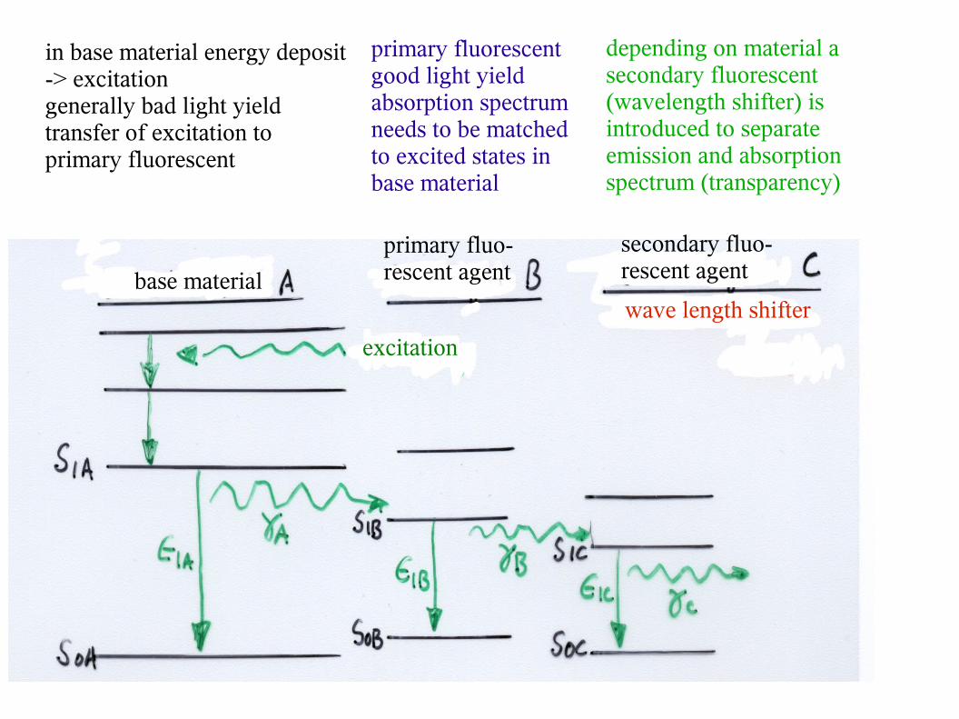
base material
primary fluo-rescent agent
secondary fluo-rescent agent
excitation
wave length shifter
in base material energy deposit-> excitationgenerally bad light yieldtransfer of excitation to primary fluorescent
primary fluorescent good light yieldabsorption spectrumneeds to be matchedto excited states in base material
depending on material asecondary fluorescent(wavelength shifter) isintroduced to separateemission and absorptionspectrum (transparency)
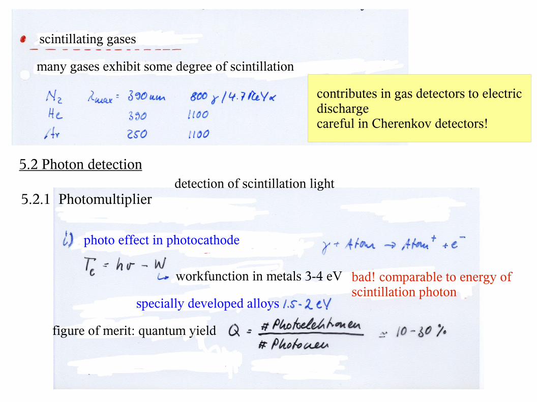
scintillating gases
many gases exhibit some degree of scintillation
contributes in gas detectors to electricdischargecareful in Cherenkov detectors!
5.2 Photon detection detection of scintillation light5.2.1 Photomultiplier
photo effect in photocathode
workfunction in metals 3-4 eV bad! comparable to energy of scintillation photon
specially developed alloys
figure of merit: quantum yield
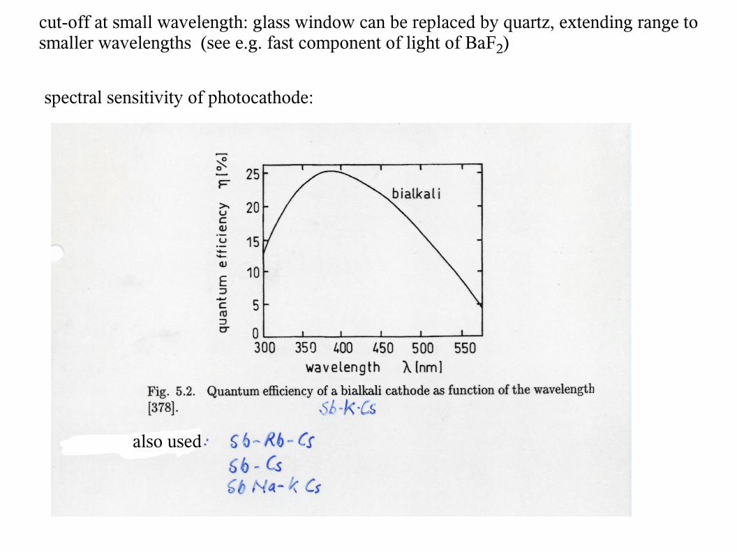
cut-off at small wavelength: glass window can be replaced by quartz, extending range to smaller wavelengths (see e.g. fast component of light of BaF2)
spectral sensitivity of photocathode:
also used
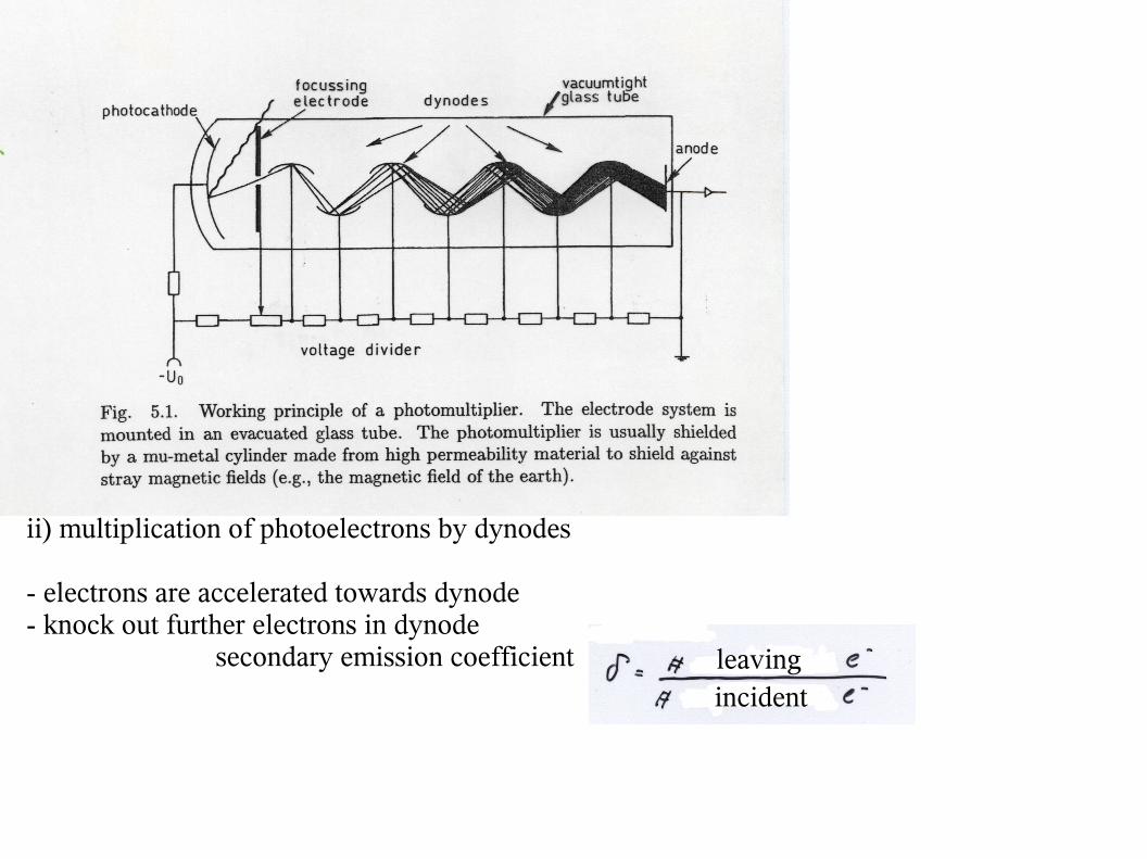
ii) multiplication of photoelectrons by dynodes
- electrons are accelerated towards dynode- knock out further electrons in dynode secondary emission coefficient leaving
incident
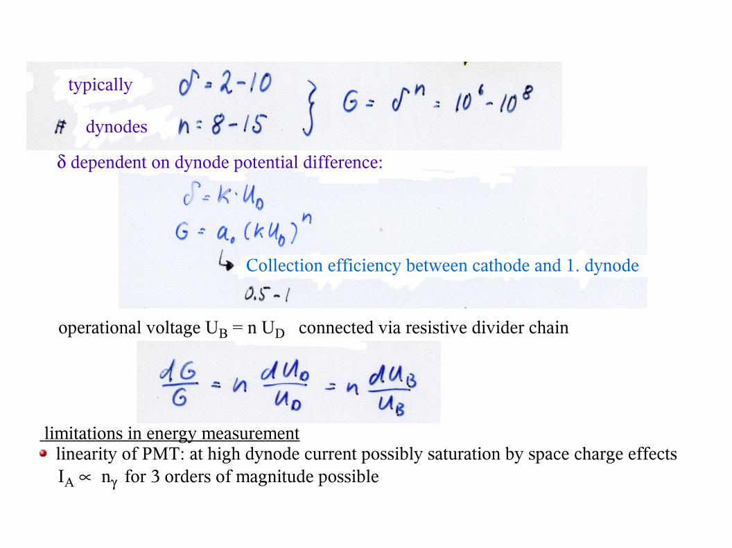
typically
dynodes
Collection efficiency between cathode and 1. dynode
dependent on dynode potential difference:
operational voltage UB = n UD connected via resistive divider chain
limitations in energy measurement linearity of PMT: at high dynode current possibly saturation by space charge effects
IA n for 3 orders of magnitude possible
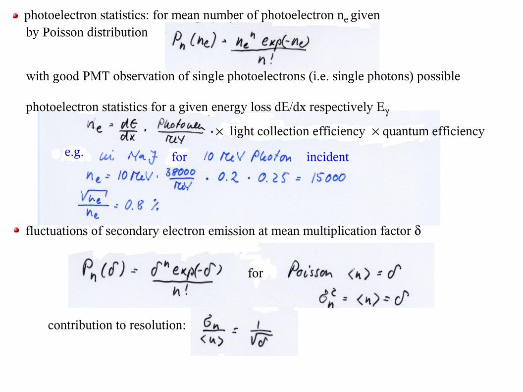
photoelectron statistics: for mean number of photoelectron ne given by Poisson distribution
with good PMT observation of single photoelectrons (i.e. single photons) possible
photoelectron statistics for a given energy loss dE/dx respectively E
light collection efficiency quantum efficiency
e.g. for incident
fluctuations of secondary electron emission at mean multiplication factor
for
contribution to resolution:
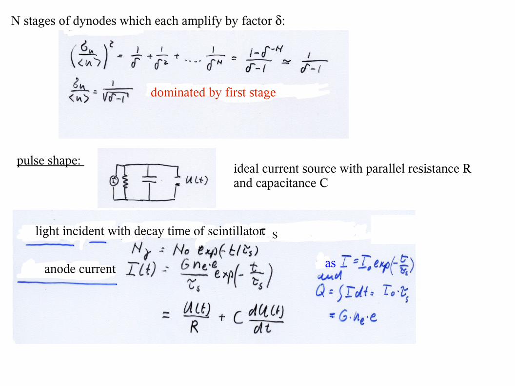
N stages of dynodes which each amplify by factor :
dominated by first stage
pulse shape: ideal current source with parallel resistance Rand capacitance C
light incident with decay time of scintillator S
anode current as
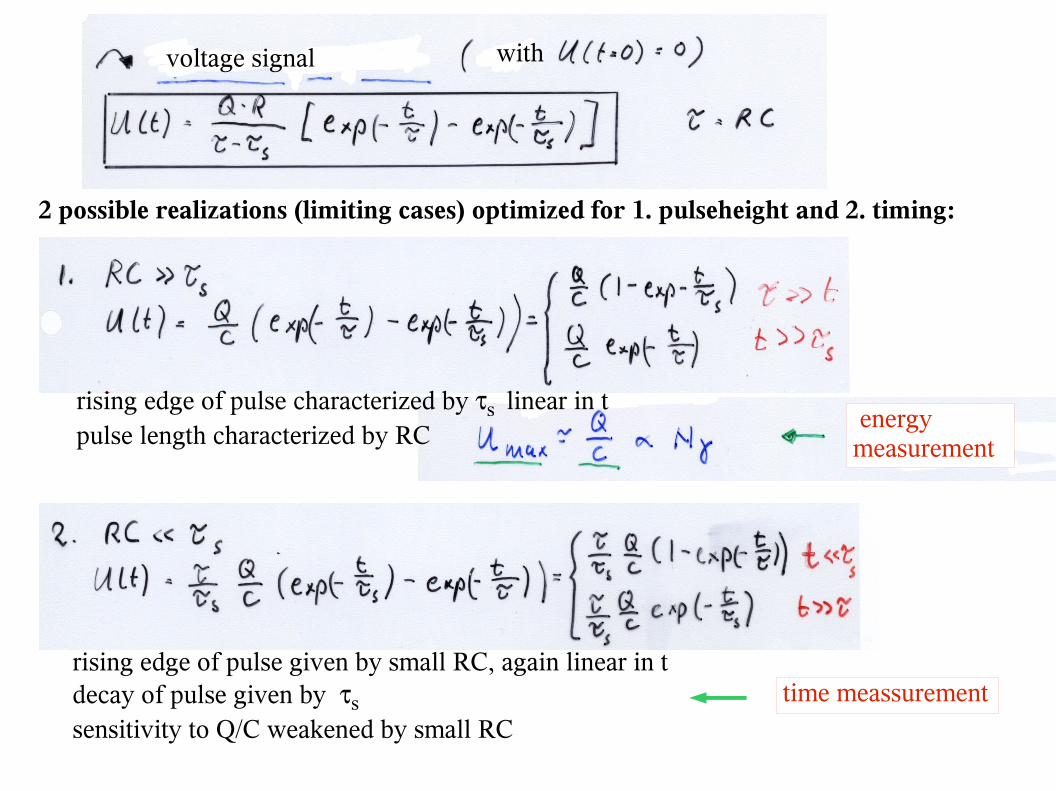
voltage signal with
2 possible realizations (limiting cases) optimized for 1. pulseheight and 2. timing:
rising edge of pulse characterized by s linear in t pulse length characterized by RC
energy measurement
rising edge of pulse given by small RC, again linear in tdecay of pulse given by s
sensitivity to Q/C weakened by small RC time meassurement
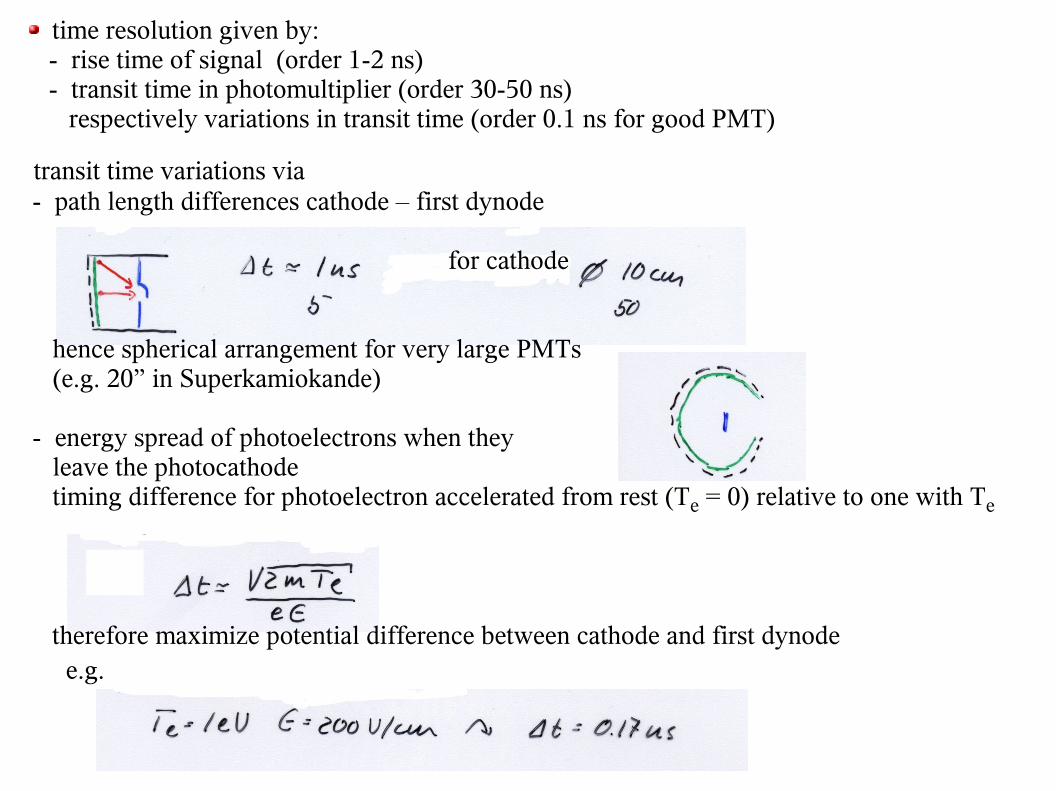
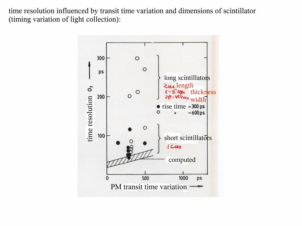
time resolution given by: - rise time of signal (order 1-2 ns) - transit time in photomultiplier (order 30-50 ns) respectively variations in transit time (order 0.1 ns for good PMT)
transit time variations via - path length differences cathode – first dynode
for cathode
hence spherical arrangement for very large PMTs (e.g. 20” in Superkamiokande)
- energy spread of photoelectrons when they leave the photocathode timing difference for photoelectron accelerated from rest (Te = 0) relative to one with Te
therefore maximize potential difference between cathode and first dynode e.g.
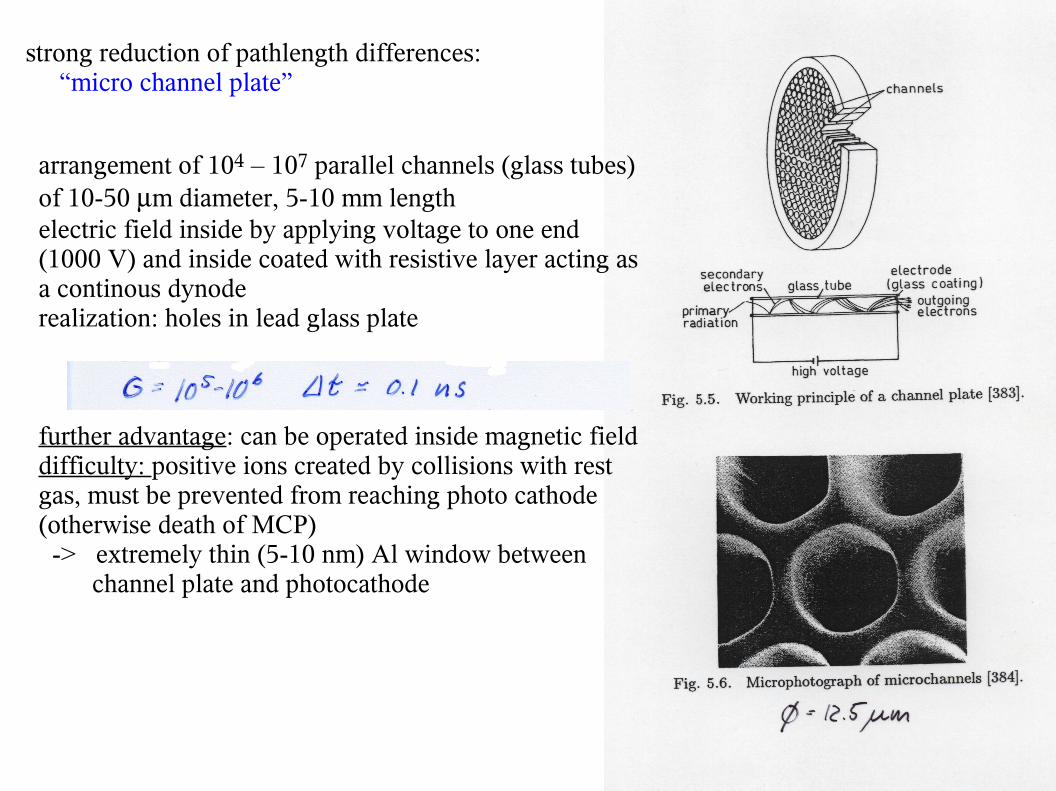
strong reduction of pathlength differences: “micro channel plate”
arrangement of 104 – 107 parallel channels (glass tubes) of 10-50 m diameter, 5-10 mm lengthelectric field inside by applying voltage to one end(1000 V) and inside coated with resistive layer acting as a continous dynoderealization: holes in lead glass plate
further advantage: can be operated inside magnetic fielddifficulty: positive ions created by collisions with rest gas, must be prevented from reaching photo cathode (otherwise death of MCP) -> extremely thin (5-10 nm) Al window between channel plate and photocathode
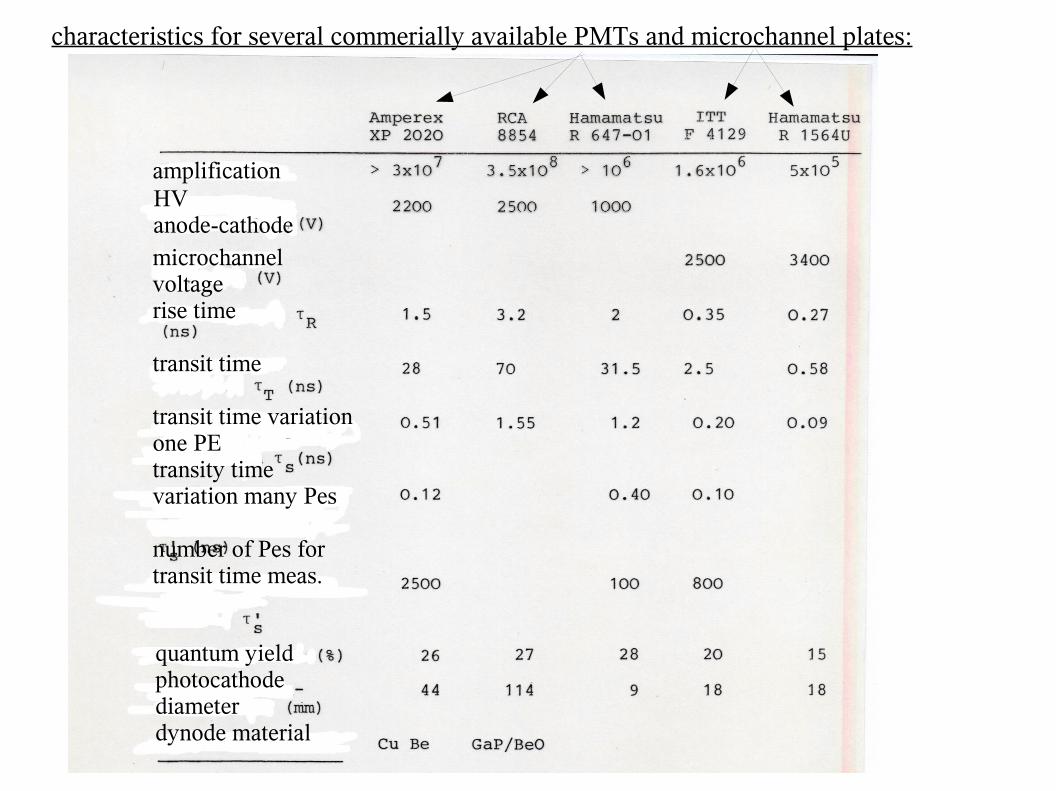
characteristics for several commerially available PMTs and microchannel plates:
amplificationHV anode-cathodemicrochannel voltagerise time
transit time
transit time variation one PEtransity time variation many Pes
number of Pes for transit time meas.
quantum yieldphotocathode diameterdynode material
long scintillators length
thicknesswidth
rise time
PM transit time variation
time
reso
luti
on
short scintillators
computed
time resolution influenced by transit time variation and dimensions of scintillator (timing variation of light collection):
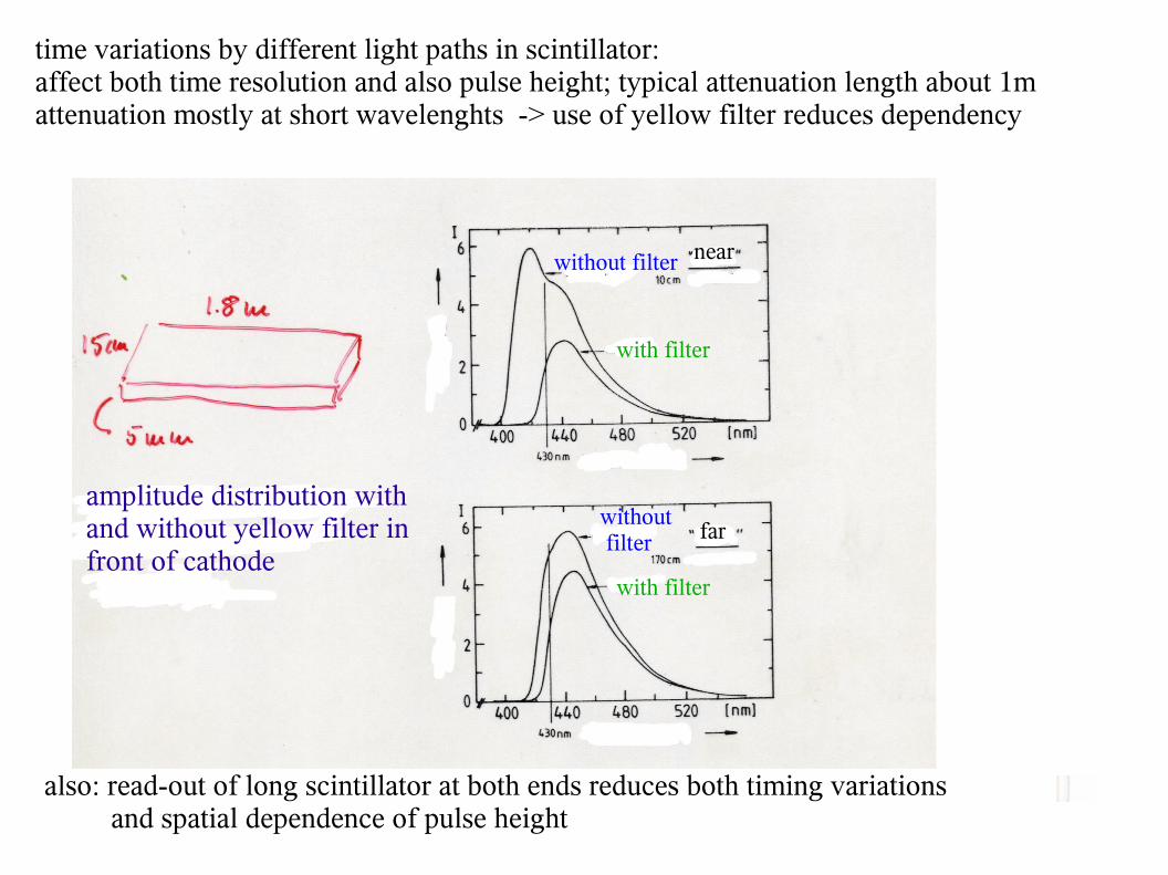
time variations by different light paths in scintillator:affect both time resolution and also pulse height; typical attenuation length about 1mattenuation mostly at short wavelenghts -> use of yellow filter reduces dependency
near
far
with filter
without filter
without filter
with filter
amplitude distribution with and without yellow filter in front of cathode
also: read-out of long scintillator at both ends reduces both timing variations and spatial dependence of pulse height
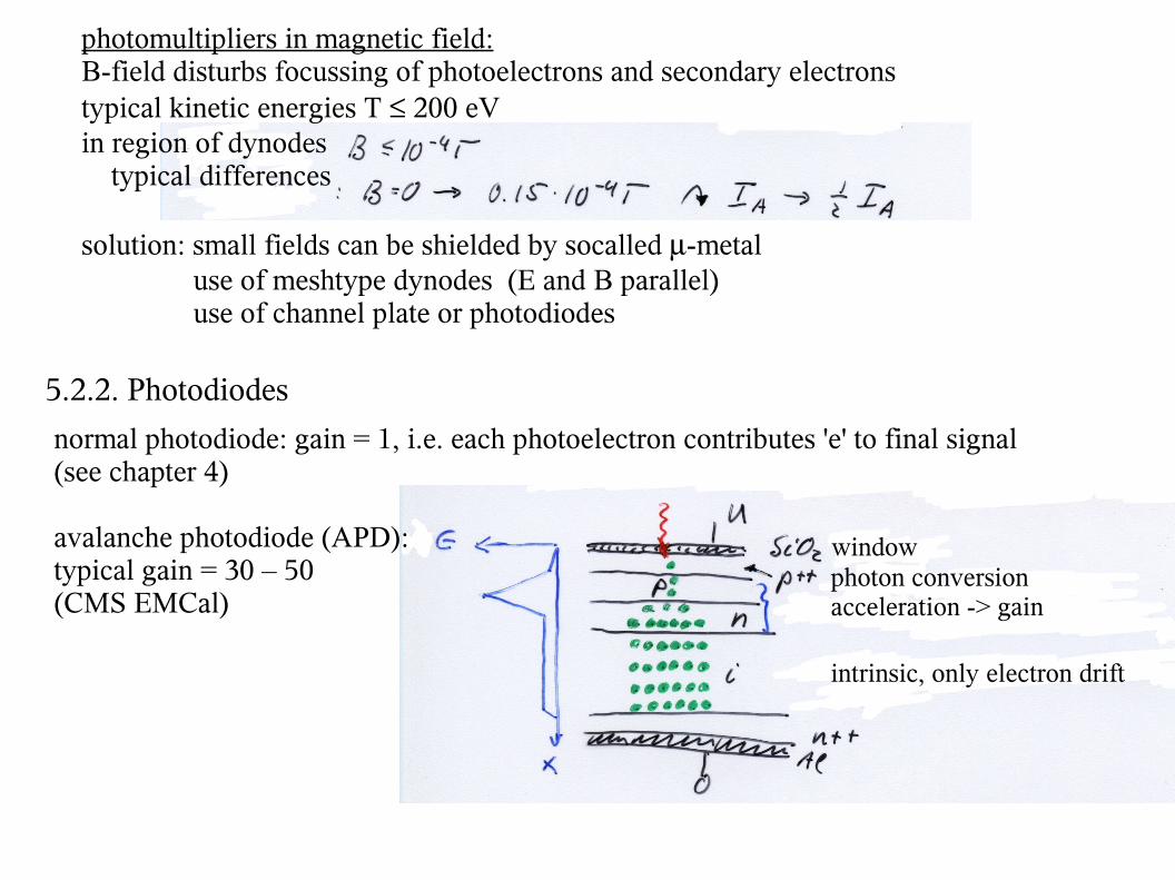
photomultipliers in magnetic field:B-field disturbs focussing of photoelectrons and secondary electronstypical kinetic energies T 200 eVin region of dynodes typical differences
solution: small fields can be shielded by socalled -metal use of meshtype dynodes (E and B parallel) use of channel plate or photodiodes
5.2.2. Photodiodes
normal photodiode: gain = 1, i.e. each photoelectron contributes 'e' to final signal (see chapter 4)
avalanche photodiode (APD):typical gain = 30 – 50(CMS EMCal)
windowphoton conversionacceleration -> gain
intrinsic, only electron drift
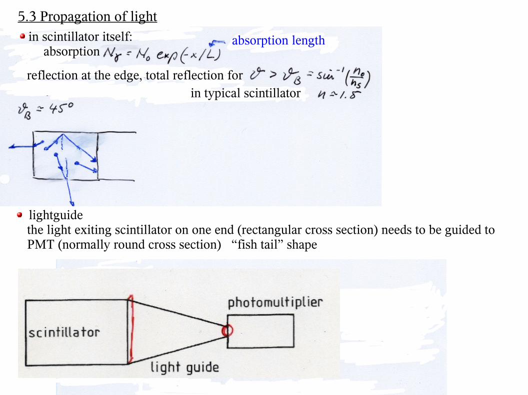
5.3 Propagation of light in scintillator itself:
absorptionabsorption length
reflection at the edge, total reflection forin typical scintillator
lightguide the light exiting scintillator on one end (rectangular cross section) needs to be guided to PMT (normally round cross section) “fish tail” shape
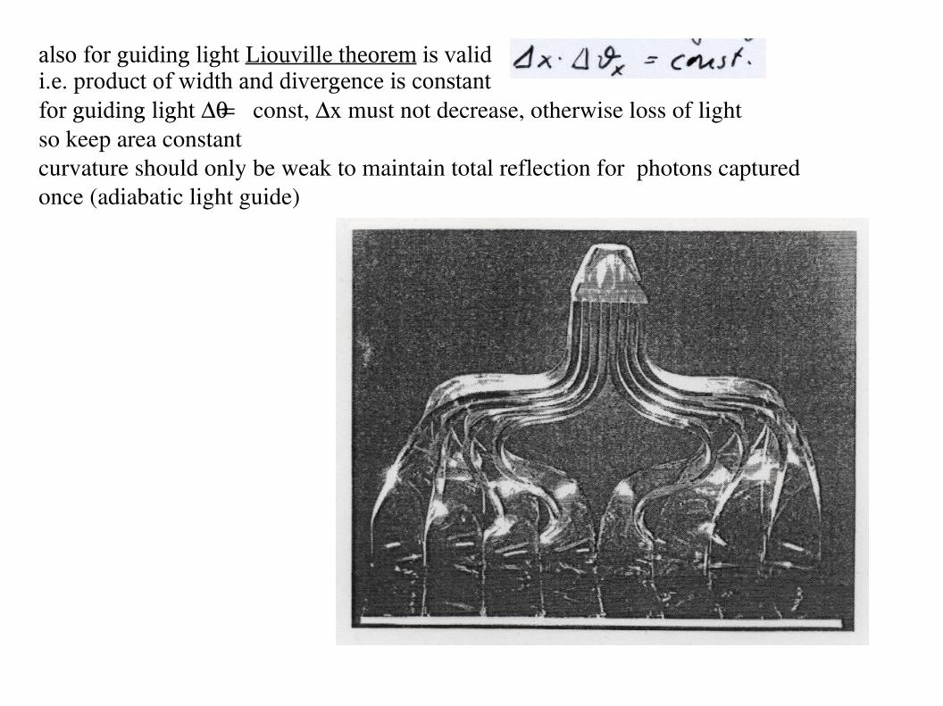
also for guiding light Liouville theorem is validi.e. product of width and divergence is constantfor guiding light const, x must not decrease, otherwise loss of lightso keep area constantcurvature should only be weak to maintain total reflection for photons captured once (adiabatic light guide)
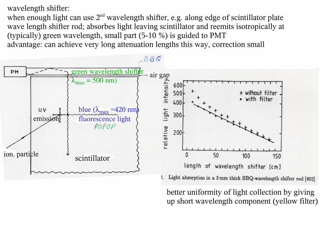
wavelength shifter: when enough light can use 2nd wavelength shifter, e.g. along edge of scintillator platewave length shifter rod; absorbes light leaving scintillator and reemits isotropically at (typically) green wavelength, small part (5-10 %) is guided to PMTadvantage: can achieve very long attenuation lengths this way, correction small
green wavelength shiftermax = 500 nm)
ion. particle
emissionblue (max =420 nm)fluorescence light
scintillator
better uniformity of light collection by givingup short wavelength component (yellow filter)
air gap
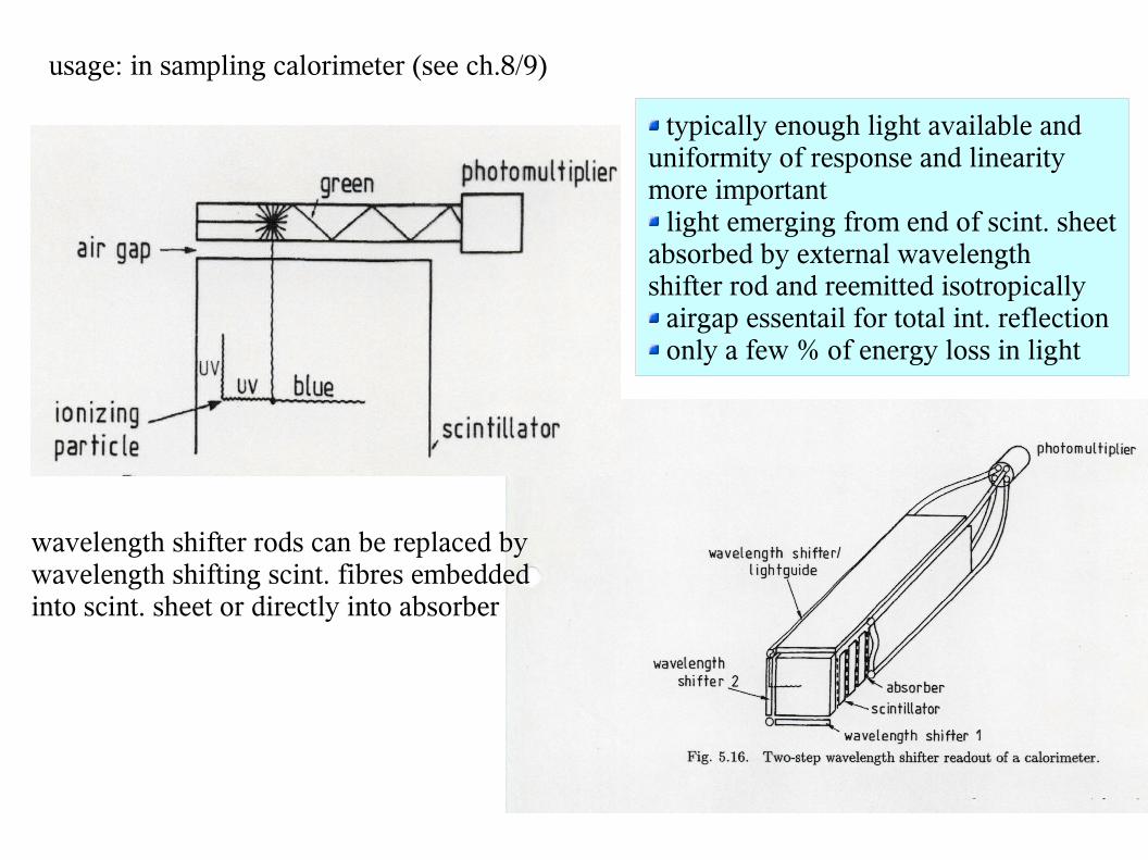
usage: in sampling calorimeter (see ch.8/9)
typically enough light available anduniformity of response and linearitymore important light emerging from end of scint. sheet
absorbed by external wavelengthshifter rod and reemitted isotropically airgap essentail for total int. reflection only a few % of energy loss in light
wavelength shifter rods can be replaced bywavelength shifting scint. fibres embeddedinto scint. sheet or directly into absorber
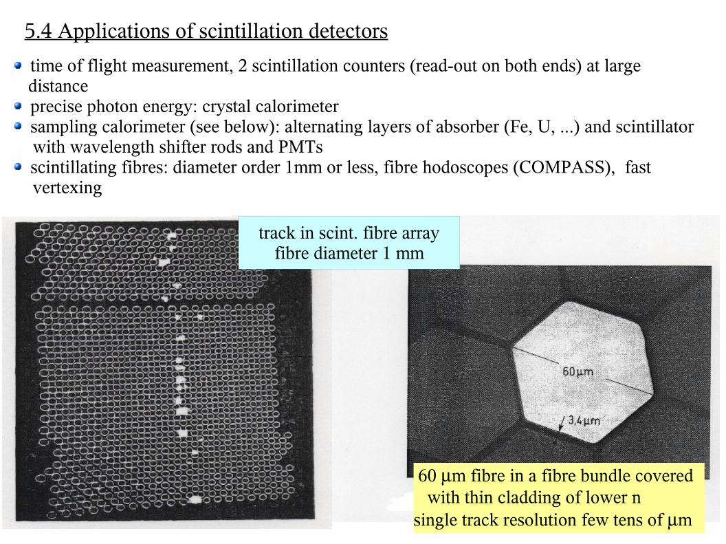
5.4 Applications of scintillation detectors
time of flight measurement, 2 scintillation counters (read-out on both ends) at large distance precise photon energy: crystal calorimeter sampling calorimeter (see below): alternating layers of absorber (Fe, U, ...) and scintillator
with wavelength shifter rods and PMTs scintillating fibres: diameter order 1mm or less, fibre hodoscopes (COMPASS), fast
vertexing
60 m fibre in a fibre bundle covered with thin cladding of lower nsingle track resolution few tens of m
track in scint. fibre arrayfibre diameter 1 mm
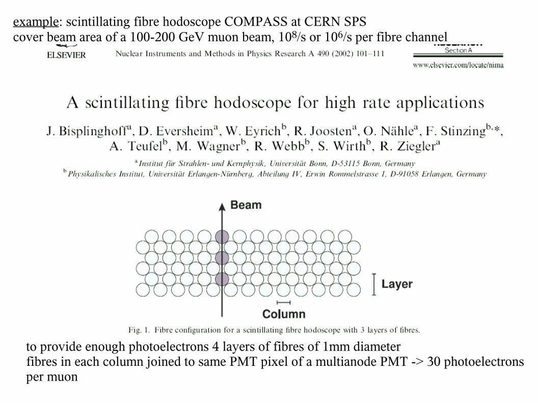
example: scintillating fibre hodoscope COMPASS at CERN SPScover beam area of a 100-200 GeV muon beam, 108/s or 106/s per fibre channel
to provide enough photoelectrons 4 layers of fibres of 1mm diameterfibres in each column joined to same PMT pixel of a multianode PMT -> 30 photoelectrons per muon
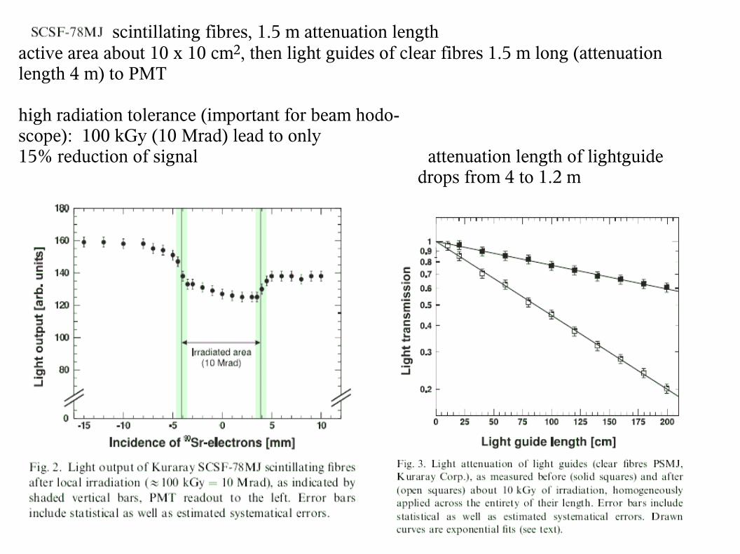
scintillating fibres, 1.5 m attenuation lengthactive area about 10 x 10 cm2, then light guides of clear fibres 1.5 m long (attenuation length 4 m) to PMT
high radiation tolerance (important for beam hodo-scope): 100 kGy (10 Mrad) lead to only 15% reduction of signal attenuation length of lightguide drops from 4 to 1.2 m
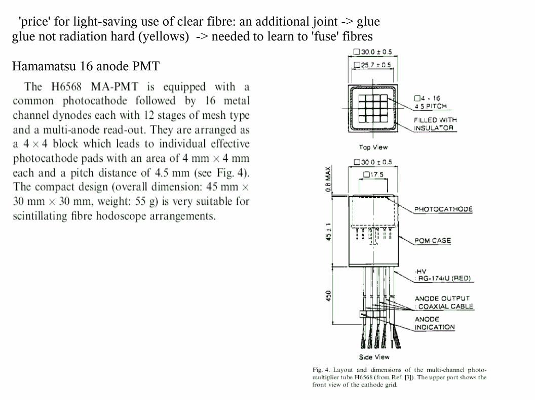
'price' for light-saving use of clear fibre: an additional joint -> glue glue not radiation hard (yellows) -> needed to learn to 'fuse' fibres
Hamamatsu 16 anode PMT
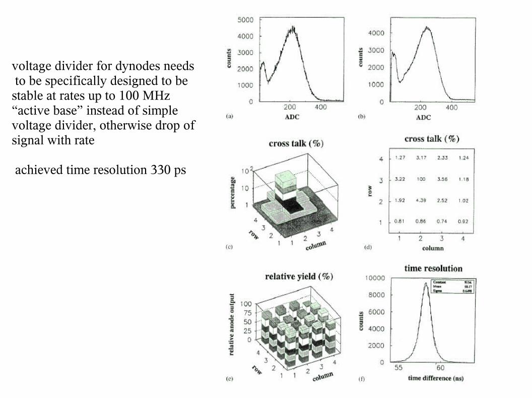
voltage divider for dynodes needs to be specifically designed to be stable at rates up to 100 MHz “active base” instead of simple voltage divider, otherwise drop of signal with rate
achieved time resolution 330 ps