5-inch 4-way modified open grid - steel bridge 4-way modified open grid ... @ 7.5" c/c 5...
TRANSCRIPT
Style / Main Beam Size & Spacing
Section Modulus (in3/ft)*50 ksi Steel Max Continuous Clear Span HS25 Wheel Load Approximate**
Weight (lbs/SF)Top Bottom L/800 Deflect 27 ksi Stress
4 Way M / 5.3# @ 7.5" 4.038 4.321 4.81 ft. 6.71 ft. 18.5
* Section modulus based on 50% of the diagonal bars active.** The deck weight psf is based on an uncoated standard panel width of 7'-8", actual weights may vary due to panel widths used, coating weight and deck attachments.
NOTE: The information contained herein has been prepared in accordance with generally accepted engineering principles. However, L.B. Foster Company is not responsible for any errors that may be contained herein. The user of the information provided herein should check the information supplied and make an independent determination as to its applicability to any particular project or application.
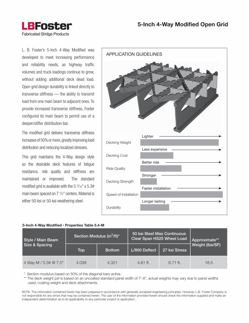
L. B. Foster’s 5-Inch 4-Way Modified was
developed to meet increasing performance
and reliability needs, as highway traffic
volumes and truck loadings continue to grow,
without adding additional deck dead load.
Open grid design durability is linked directly to
transverse stiffness — the ability to transmit
load from one main beam to adjacent ones. To
provide increased transverse stiffness, Foster
configured its main beam to permit use of a
deeper/stiffer distribution bar.
The modified grid delivers transverse stiffness
increases of 50% or more, greatly improving load
distribution and reducing localized stresses.
This grid maintains the 4-Way design style
so the desirable deck features of fatigue
resistance, ride quality and stiffness are
maintained or improved. The standard
modified grid is available with the 5 3/16" x 5.3#
main beam spaced on 7 1/2" centers. Material is
either 50-ksi or 50-ksi weathering steel.
5-Inch 4-Way Modified Open Grid
APPLICATION GUIDELINES
5-Inch 4-Way Modified • Properties Table 5.4-M
Lighter
Decking Weight
Less expensive
Decking Cost
Better ride
Ride Quality
Stronger
Decking Strength
Faster installation
Speed of Installation
Longer lasting
Durability

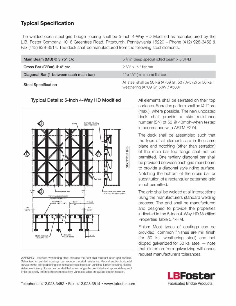
Main Beam (MB) @ 7.5" c/c 5 3/16" deep special rolled beam x 5.3#/LF
Cross Bar (C’Bar) @ 4" c/c 2 1/2" x 1/4" flat bar
Diagonal Bar (2 between each main bar) 1" x 1/4" (minimum) flat bar
Supplemental Bar @ 7.5" c/c 1" x 1/4" (minimum) flat bar
Steel SpecificationAll steel shall be 50 ksi (A709 Gr. 50 / A-572) or 50 ksi weathering (A709 Gr. 50W / A-588)
Typical SpecificationThe welded open steel grid bridge flooring shall be 5-Inch 4-Way Modified as manufactured by the L.B. Foster Company, 1016 Greentree Road, Pittsburgh, Pennsylvania 15220 – Phone (412) 928-3452 & Fax (412) 928-3514. The deck shall be manufactured from the following steel elements:
All elements shall be serrated on their top surfaces. Serration pattern shall be @ 1" c/c (max.), where possible. The new uncoated deck shall provide a skid resistance number (SN) of 53 @ 40mph-when tested in accordance with ASTM E274.
The deck shall be assembled such that the tops of all elements are in the same plane and notching (other than serration) of the main bar top flange shall not be permitted. Two tertiary diagonal bars shall be provided between each grid main beam to provide a diagonal style riding surface. Notching the bottom of the cross bar or substitution of a rectangular pattered grid is not permitted.
The grid shall be welded at all intersections using the manufacturers standard welding process. The grid shall be manufactured and designed to provide the properties indicated in the 5-Inch 4-Way Properties Table 5.4-M.
Finish: Most types of coatings can be provided; common finishes are mill finish (for 50 ksi weathering steel) and hot dipped galvanized for 50 ksi steel — note that distortion from galvanizing will occur, request manufacturer’s tolerances.
WARNING: Uncoated-weathering steel provides the best skid resistant open grid surface. Gal-vanized or painted coatings can reduce the skid resistance. Vertical and/or horizontal curves on the bridge decking can increase lateral forces on vehicles, further reducing skid resistance efficiency. It is recommended that lane changes be prohibited and appropriate speed limits be strictly enforced to promote safety. Various studies are available upon request.
Telephone: 412.928.3452 • Fax: 412.928.3514 • www.lbfoster.com
Typical Details: 5-Inch 4-Way Modified
Style / Main Beam Size & Spacing
Section Modulus (in3/ft)*50 ksi Steel Max Continuous Clear Span HS25 Wheel Load Approximate**
Weight (lbs/SF)Top Bottom L/800 Deflect 27 ksi Stress
4 way / 5.3# @ 3.75" 5.588 8.100 5.45 ft. 7.41 ft. 25.8
* Section modulus based on 50% of the diagonal bars active.** The deck weight psf is based on an uncoated standard panel width of 7'-8", actual weights may vary due to panel widths used, coating weight and deck attachments.
NOTE: The information contained herein has been prepared in accordance with generally accepted engineering principles. However, L.B. Foster Company is not responsible for any errors that may be contained herein. The user of the information provided herein should check the information supplied and make an independent determination as to its applicability to any particular project or application.
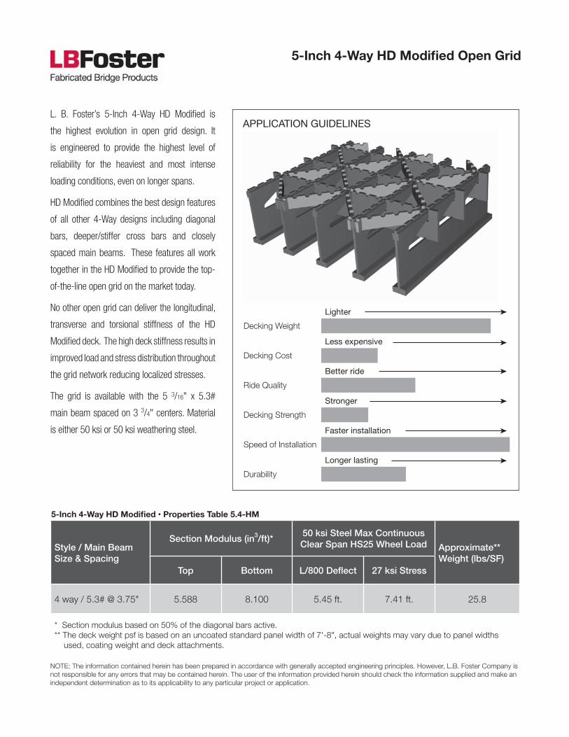
L. B. Foster’s 5-Inch 4-Way HD Modified is
the highest evolution in open grid design. It
is engineered to provide the highest level of
reliability for the heaviest and most intense
loading conditions, even on longer spans.
HD Modified combines the best design features
of all other 4-Way designs including diagonal
bars, deeper/stiffer cross bars and closely
spaced main beams. These features all work
together in the HD Modified to provide the top-
of-the-line open grid on the market today.
No other open grid can deliver the longitudinal,
transverse and torsional stiffness of the HD
Modified deck. The high deck stiffness results in
improved load and stress distribution throughout
the grid network reducing localized stresses.
The grid is available with the 5 3/16" x 5.3#
main beam spaced on 3 3/4" centers. Material
is either 50 ksi or 50 ksi weathering steel.
5-Inch 4-Way HD Modified Open Grid
APPLICATION GUIDELINES
5-Inch 4-Way HD Modified • Properties Table 5.4-HM
Lighter
Decking Weight
Less expensive
Decking Cost
Better ride
Ride Quality
Stronger
Decking Strength
Faster installation
Speed of Installation
Longer lasting
Durability
Main Beam (MB) @ 3.75" c/c 5 3/16" deep special rolled beam x 5.3#/LF
Cross Bar (C’Bar) @ 4" c/c 2 1/2" x 1/4" flat bar
Diagonal Bar (1 between each main bar) 1" x 1/4" (minimum) flat bar
Steel SpecificationAll steel shall be 50 ksi (A709 Gr. 50 / A-572) or 50 ksi weathering (A709 Gr. 50W / A588)
Typical Specification
All elements shall be serrated on their top surfaces. Serration pattern shall be @ 1" c/c (max.), where possible. The new uncoated deck shall provide a skid resistance number (SN) of 53 @ 40mph-when tested in accordance with ASTM E274.
The deck shall be assembled such that the tops of all elements are in the same plane and notching (other than serration) of the main bar top flange shall not be permitted. One tertiary diagonal bar shall be provided between each grid main beam to provide a diagonal style riding surface. Notching the bottom of the cross bar or substitution of a rectangular patterned grid is not permitted.
The grid shall be welded at all intersections using the manufacturers standard welding process. The grid shall be manufactured and designed to provide the properties indicated in the 5-Inch 4-Way HD Modified Properties Table 5.4-HM.
Finish: Most types of coatings can be provided; common finishes are mill finish (for 50 ksi weathering steel) and hot dipped galvanized for 50 ksi steel — note that distortion from galvanizing will occur, request manufacturer’s tolerances.
WARNING: Uncoated-weathering steel provides the best skid resistant open grid surface. Galvanized or painted coatings can reduce the skid resistance. Vertical and/or horizontal curves on the bridge decking can increase lateral forces on vehicles, further reducing skid re-sistance efficiency. It is recommended that lane changes be prohibited and appropriate speed limits be strictly enforced to promote safety. Various studies are available upon request.
Telephone: 412.928.3452 • Fax: 412.928.3514 • www.lbfoster.com
Typical Details: 5-Inch 4-Way HD Modified
The welded open steel grid bridge flooring shall be 5-Inch 4-Way HD Modified as manufactured by the L.B. Foster Company, 1016 Greentree Road, Pittsburgh, Pennsylvania 15220 – Phone (412) 928-3452 & Fax (412) 928-3514. The deck shall be manufactured from the following steel elements:

Style / Main Beam Size & Spacing
Section Modulus (in3/ft)*50 ksi Steel Max Continuous Clear Span HS25 Wheel Load Approximate**
Weight (lbs/SF)Top Bottom L/800 Deflect 27 ksi Stress
RB 4.2M / 5.3# @ 4" 6.421 7.889 5.69 ft. 8.48 ft. 25.4
* Section modulus based on 50% of the supplemental bars active.** The deck weight psf is based on an uncoated standard panel width of 8'-2", actual weights may vary due to panel widths used, coating weight and deck attachments.
NOTE: The information contained herein has been prepared in accordance with generally accepted engineering principles. However, L.B. Foster Company is not responsible for any errors that may be contained herein. The user of the information provided herein should check the information supplied and make an independent determination as to its applicability to any particular project or application.
L. B. Foster’s 5-Inch RB 4.2M is designed to
provide increased load carrying capability and
longer span capacity compared to the lighter RB
6.2M and RB 8.2M open grid designs. It’s 4"
spaced main beams and two supplemental bars
yield a more balanced section than RB 3.0M
resulting in greater load and span capabilities
with no added weight.
The Modified grid delivers transverse stiffness
increases of 50% or more when compared
to the outdated 2" deep cross bars offered
on some older open grid designs. The deeper
cross bars greatly improve load distribution and
reduce localized stresses.
This rectangular patterned deck is suitable for
lower traffic volume structures where the 4-
Way style grids may not be required. However,
the close spaced main beam design permits its
use on longer spans and for heavy loads.
5-Inch RB 4.2M Open Grid
APPLICATION GUIDELINES
5-Inch RB 4.2M • Properties Table 5.4.2M
Lighter
Decking Weight
Less expensive
Decking Cost
Better ride
Ride Quality
Stronger
Decking Strength
Faster installation
Speed of Installation
Longer lasting
Durability
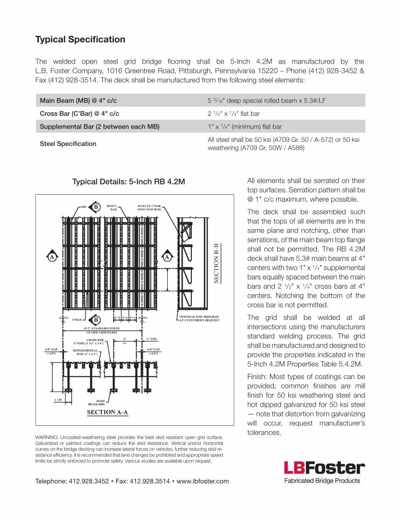
Main Beam (MB) @ 4" c/c 5 3/16" deep special rolled beam x 5.3#/LF
Cross Bar (C’Bar) @ 4" c/c 2 1/2" x 1/4" flat bar
Supplemental Bar (2 between each MB) 1" x 1/4" (minimum) flat bar
Steel SpecificationAll steel shall be 50 ksi (A709 Gr. 50 / A-572) or 50 ksi weathering (A709 Gr. 50W / A588)
Typical Specification
All elements shall be serrated on their top surfaces. Serration pattern shall be @ 1" c/c maximum, where possible.
The deck shall be assembled such that the tops of all elements are in the same plane and notching, other than serrations, of the main beam top flange shall not be permitted. The RB 4.2M deck shall have 5.3# main beams at 4" centers with two 1" x 1/4" supplemental bars equally spaced between the main bars and 2 1/2" x 1/4" cross bars at 4" centers. Notching the bottom of the cross bar is not permitted.
The grid shall be welded at all intersections using the manufacturers standard welding process. The grid shall be manufactured and designed to provide the properties indicated in the 5-Inch 4.2M Properties Table 5.4.2M.
Finish: Most types of coatings can be provided; common finishes are mill finish for 50 ksi weathering steel and hot dipped galvanized for 50 ksi steel — note that distortion from galvanizing will occur, request manufacturer’s tolerances.
WARNING: Uncoated-weathering steel provides the best skid resistant open grid surface. Galvanized or painted coatings can reduce the skid resistance. Vertical and/or horizontal curves on the bridge decking can increase lateral forces on vehicles, further reducing skid re-sistance efficiency. It is recommended that lane changes be prohibited and appropriate speed limits be strictly enforced to promote safety. Various studies are available upon request.
Telephone: 412.928.3452 • Fax: 412.928.3514 • www.lbfoster.com
Typical Details: 5-Inch RB 4.2M
The welded open steel grid bridge flooring shall be 5-Inch 4.2M as manufactured by the L.B. Foster Company, 1016 Greentree Road, Pittsburgh, Pennsylvania 15220 – Phone (412) 928-3452 & Fax (412) 928-3514. The deck shall be manufactured from the following steel elements:

Style / Main Beam Size & Spacing
Section Modulus (in3/ft)*50 ksi Steel Max Continuous Clear Span HS25 Wheel Load Approximate**
Weight (lbs/SF)Top Bottom L/800 Deflect 27 ksi Stress
RB 6.2M / 5.3# @ 6" 4.281 5.260 4.93 ft. 6.59 ft. 19.2
* Section modulus based on 50% of the supplemental bars active.** The deck weight psf is based on an uncoated standard panel width of 7'-8", actual weights may vary due to panel widths used, coating weight and deck attachments.
NOTE: The information contained herein has been prepared in accordance with generally accepted engineering principles. However, L.B. Foster Company is not responsible for any errors that may be contained herein. The user of the information provided herein should check the information supplied and make an independent determination as to its applicability to any particular project or application.
L. B. Foster’s 5-Inch RB 6.2M is the most
commonly used of the RB series rectangular
patterned open grids. RB 6.2M offers the
best compromise of deck weight to load and
span capability for the RB style rectangular
patterned decks.
Open grid design durability is linked directly to
transverse stiffness — the ability to transmit
load from one main beam to adjacent ones. To
provide increased transverse stiffness, Foster
configured its main beam to permit use of a
deeper/stiffer distribution bar.
The modified grid delivers transverse stiffness
increases of 50% or more when compared to
the outdated 2" deep cross bars offered on
some older open grid designs. The deeper
cross bars greatly improve load distribution
and reduce localized stresses.
If the superior 4-way riding surface is not
required, this design is suitable for use on low
speed, low to moderate traffic volume structures
where the ADTT and deck spans are modest.
5-Inch RB 6.2M Open Grid
APPLICATION GUIDELINES
5-Inch RB 6.2M • Properties Table 5.6.2M
Lighter
Decking Weight
Less expensive
Decking Cost
Better ride
Ride Quality
Stronger
Decking Strength
Faster installation
Speed of Installation
Longer lasting
Durability

Main Beam (MB) @ 6" c/c 5 3/16" deep special rolled beam x 5.3#/LF
Cross Bar (C’Bar) @ 4" c/c 2 1/2" x 1/4" flat bar
Supplemental Bar (2 between each MB) 1" x 1/4" (minimum) flat bar
Steel SpecificationAll steel shall be 50 ksi (A709 Gr. 50 / A-572) or 50 ksi weathering (A709 Gr. 50W / A588)
Typical Specification
All elements shall be serrated on their top surfaces. Serration pattern shall be @ 1" c/c (max.), where possible.
The deck shall be assembled such that the tops of all elements are in the same plane and notching (other than serration) of the main beam top flange shall not be permitted. The RB 6.2 deck shall have 5.3# main beams at 6" centers with two 1" x 1/4" supple-mental bars equally spaced between them and 2 1/2" x 1/4" cross bars at 4" centers. Notching the bottom of the cross bar is not permitted.
The grid shall be welded at all inter-sections using the manufacturers standard welding process. The grid shall be manufactured and designed to provide the properties indicated in the 5-Inch RB 6.2M Properties Table 5.6.2.
Finish: Most types of coatings can be provided; common finishes are mill finish (for 50 ksi weathering steel) and hot dipped galvanized for 50 ksi steel — note that distortion from galvaniz-ing will occur, request manufacturer’s tolerances.WARNING: Uncoated-weathering steel provides the best skid resistant open grid surface.
Galvanized or painted coatings can reduce the skid resistance. Vertical and/or horizontal curves on the bridge decking can increase lateral forces on vehicles, further reducing skid re-sistance efficiency. It is recommended that lane changes be prohibited and appropriate speed limits be strictly enforced to promote safety. Various studies are available upon request.
Telephone: 412.928.3452 • Fax: 412.928.3514 • www.lbfoster.com
Typical Details: 5-Inch RB 6.2M
The welded open steel grid bridge flooring shall be 5-Inch RB 6.2M as manufactured by the L.B. Foster Company, 1016 Greentree Road, Pittsburgh, Pennsylvania 15220 – Phone (412) 928-3452 & Fax (412) 928-3514. The deck shall be manufactured from the following steel elements:

Style / Main Beam Size & Spacing
Section Modulus (in3/ft)*50 ksi Steel Max Continuous Clear Span HS25 Wheel Load Approximate**
Weight (lbs/SF)Top Bottom L/800 Deflect 27 ksi Stress
RB 8.2 / 5.3# @ 8" 3.219 3.955 4.49 ft. 5.66 ft. 16.4
* Section modulus based on 50% of the supplemental bars active.** The deck weight psf is based on an uncoated standard panel width of 8'-2", actual weights may vary due to panel widths used, coating weight and deck attachments.
NOTE: The information contained herein has been prepared in accordance with generally accepted engineering principles. However, L.B. Foster Company is not responsible for any errors that may be contained herein. The user of the information provided herein should check the information supplied and make an independent determination as to its applicability to any particular project or application.
L. B. Foster’s 5-Inch RB 8.2M is generally
recommended for light duty and / or temporary
applications with shorter span lengths and
lighter loads. RB 8.2M offers a less expensive
alternative where a more heavy duty deck is not
required.
Open grid design durability is linked directly
to transverse stiffness, the ability to transmit
load from one main beam to adjacent ones. To
provide increased transverse stiffness, Foster
reconfigured its main beam to permit use of a
deeper/stiffer distribution bar.
The Modified grid delivers transverse stiffness
increases of 50% or more when compared to
the outdated 2" deep cross bars offered on
some older open grid designs. The deeper
cross bars greatly improve load distribution and
reduce localized stresses.
If the superior 4-Way riding surface is not
required, this design is suitable for use on low
speed, low to moderate traffic volume structures
where the ADTT and deck spans are modest.
5-Inch RB 8.2 M Open Grid
APPLICATION GUIDELINES
5-Inch RB 8.2M • Properties Table 5.8.2M
Lighter
Decking Weight
Less expensive
Decking Cost
Better ride
Ride Quality
Stronger
Decking Strength
Faster installation
Speed of Installation
Longer lasting
Durability

Main Beam (MB) @ 8" c/c 5 3/16" deep special rolled beam x 5.3#/LF
Cross Bar (C’Bar) @ 4" c/c 2 1/2" x 1/4" flat bar
Supplemental Bar (2 between each MB) 1" x 1/4" (minimum) flat bar
Steel SpecificationAll steel shall be 50 ksi (A709 Gr. 50 / A572) or 50 ksi weathering (A709 Gr. 50W / A588)
Typical Specification
All elements shall be serrated on their top surfaces. Serration pattern shall be @ 1"c/c (max.), where possible.
The deck shall be assembled such that the tops of all elements are in the same plane and notching (other than serration) of the main beam top flange shall not be permitted. The RB 8.2M deck shall have 5.3# main beams at 8” centers with two 1" x 1/4" supple-mental bars equally spaced between them and 2 1/2" x 1/4" cross bars at 4" centers. Notching the bottom of the cross bar is not permitted.
The grid shall be welded at all inter-sections using the manufacturer’s standard welding process. The grid shall be manufactured and designed to provide the properties indicated in the 5-Inch RB 8.2M Properties Table 5.8.2.
Finish: Most types of coatings can be provided; common finishes are mill finish (for 50 ksi weathering steel) and hot dipped galvanized for 50 ksi steel. Note that distortion from galvanizing will occur, request manufacturer’s tol-erances.
WARNING: Uncoated-weathering steel provides the best skid resistant open grid surface. Galvanized or painted coatings can reduce the skid resistance. Vertical and/or horizontal curves on the bridge decking can increase lateral forces on vehicles, further reducing skid re-sistance efficiency. It is recommended that lane changes be prohibited and appropriate speed limits be strictly enforced to promote safety. Various studies are available upon request.
Telephone: 412.928.3452 • Fax: 412.928.3514 • www.lbfoster.com
Typical Details: 5-Inch RB 8.2M
The welded open steel grid bridge flooring shall be 5-Inch RB 8.2M as manufactured by the L.B. Foster Company, 1016 Greentree Road, Pittsburgh, Pennsylvania 15220 – Phone (412) 928-3452 & Fax (412) 928-3514. The deck shall be manufactured from the following steel elements:
NOTE: The information contained herein has been prepared in accordance with generally accepted engineering principles. However, L.B. Foster Company is not responsible for any errors that may be contained herein. The user of the information provided herein should check the information supplied and make an independent determination as to its applicability to any particular project or application.
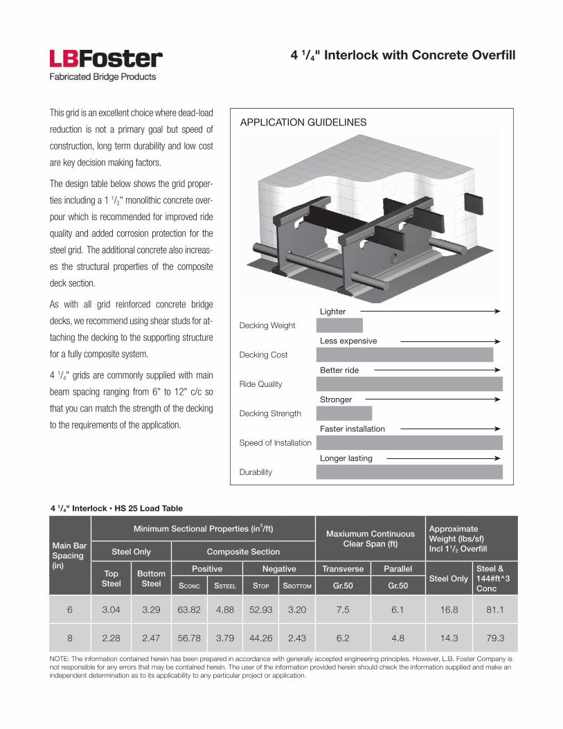
This grid is an excellent choice where dead-load
reduction is not a primary goal but speed of
construction, long term durability and low cost
are key decision making factors.
The design table below shows the grid proper-
ties including a 1 1/2" monolithic concrete over-
pour which is recommended for improved ride
quality and added corrosion protection for the
steel grid. The additional concrete also increas-
es the structural properties of the composite
deck section.
As with all grid reinforced concrete bridge
decks, we recommend using shear studs for at-
taching the decking to the supporting structure
for a fully composite system.
4 1/4" grids are commonly supplied with main
beam spacing ranging from 6" to 12" c/c so
that you can match the strength of the decking
to the requirements of the application.
4 1/4" Interlock with Concrete Overfill
APPLICATION GUIDELINES
4 1/4" Interlock • HS 25 Load Table
Main Bar Spacing (in)
Minimum Sectional Properties (in3/ft)Maxiumum Continuous
Clear Span (ft)
Approximate Weight (lbs/sf)Incl 11/2 OverfillSteel Only Composite Section
Top Steel
Bottom Steel
Positive Negative Transverse ParallelSteel Only
Steel & 144#ft^3 ConcSconc SSteel Stop Sbottom Gr.50 Gr.50
6 3.04 3.29 63.82 4.88 52.93 3.20 7.5 6.1 16.8 81.1
8 2.28 2.47 56.78 3.79 44.26 2.43 6.2 4.8 14.3 79.3
Lighter
Decking Weight
Less expensive
Decking Cost
Better ride
Ride Quality
Stronger
Decking Strength
Faster installation
Speed of Installation
Longer lasting
Durability

Main Beam (MB) @ 6" or 8" c/c 4 1/4" deep special rolled beam x 5#/LF
Cross Bar (C’Bar) @ 4" or 8" c/c 1 1/2" x 1/4" flat bar
Bottom Round Bar @ 8" c/c 5/8" Diameter round bar or #5 Rebar
Steel SpecificationAll steel shall be 50 ksi (A709 Gr. 50 / A572) or 50 ksi weathering (A709 Gr. 50W / A588)
Typical Specification
The deck shall be assembled such that the tops of all elements are in the same plane and notching of the main beam top flange shall not be permitted.
Grid assembly welding will be per manufacturer’s standard welding details.
Finish: Most types of coatings can be provided; common finishes are mill finish for 50 ksi weathering steel and hot dipped galvanized for 50 ksi steel-note that distortion from galvanizing will occur, request manufacturer’s tolerances.
Telephone: 412.928.3452 • Fax: 412.928.3514 • www.lbfoster.com
Typical Details: 4 1/4" Interlock with Concrete Overfill
The steel grid bridge flooring shall be 4 1/4" Interlock as manufactured by the L.B. Foster Company, 1016 Greentree Road, Pittsburgh, Pennsylvania 15220 – Phone (412) 928-3452 & Fax (412) 928-3514. The deck shall be manufactured from the following steel elements:
Request manufacturer’s standard 4 part product specification for inclusion with project documents.

Lighter
Decking Weight
Less expensive
Decking Cost
Better ride
Ride Quality
Stronger
Decking Strength
Faster installation
Speed of Installation Cast in place Precast
Longer lasting
Durability
Main Bar Spacing (in)
Minimum Sectional Properties (in3/ft)Maxiumum Continuous
Clear Span (ft)
Approximate Weight (lbs/sf)Incl 11/2 OverfillSteel Only Composite Section
Top Steel
Bottom Steel
Positive Negative Transverse ParallelSteel Only
Steel & 144#ft^3 ConcSconc SSteel Stop Sbottom A36 A588 A36 A588
6 4.38 5.18 91.77 7.78 4.38 5.18 8.8 10.1 6.3 8.3 19.6 65.0
NOTE: The information contained herein has been prepared in accordance with generally accepted engineering principles. However, L.B. Foster Company is not responsible for any errors that may be contained herein. The user of the information provided herein should check the information supplied and make an independent determination as to its applicability to any particular project or application.
5" RB half-filled grid products are available
with a variety of bar spacings, typically ranging
from 6" c/c to 10" c/c, but can be more or less
depending on the required loading and support
spacing. Different configurations allow the
designer to match the strength of the decking
to the requirements of the application. The 5"
RB 6.1 has grid main beams at 6" c/c and one
supplemental bar.
Because this grid is half filled with concrete it
is significantly lighter than a common rebar
reinforced slab and most fully filled grids. The
concrete provides a smooth, quiet, non-skid riding
surface. Supplemental bars that run parallel with
the grid main beams are added to help balance
out the section properties of the deck.
Grids can be made fully composite with supports
and can accommodate complex deck geometry,
cross-slopes and super-elevation. Speed of
construction, high strength to weight ratio and
excellent long term durability make these grid
systems an excellent product choice.
5-Inch RB 6.1 Half-Filled Grid w/ Overfill
APPLICATION GUIDELINES
5" RB 6.1 Half-Depth • HS 25 Load Table

Main Beam (MB) @ 6" c/c 5 3/16" deep special rolled beam x 5.6 #/LF
Cross Bar (C’Bar) @ 4" or 8” c/c 2" x 1/4" flat bar
Supplemental Bar (1 between each MB) 1" x 1/4" (minimum) flat bar
Steel SpecificationAll steel shall be 50 ksi (A709 Gr. 50 / A-572) or 50 ksi weathering (A709 Gr. 50W / A588)
Typical Specification
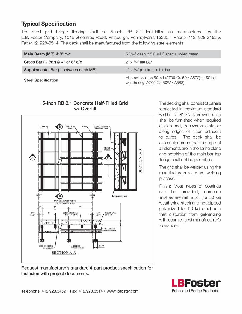
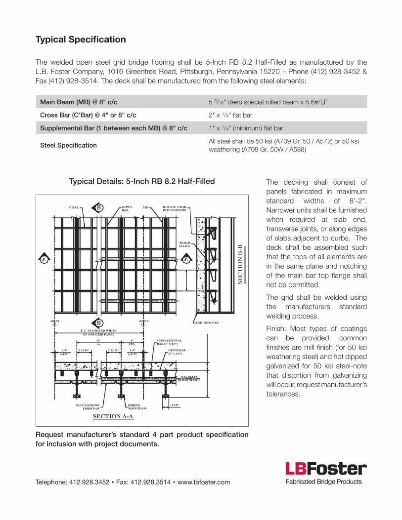
The decking shall consist of panels fabricated in maximum standard widths of 8-0". Narrower units shall be furnished when required at slab end, transverse joints, or along edges of slabs adjacent to curbs. The deck shall be assembled such that the tops of all elements are in the same plane and notching of the main bar top flange shall not be permitted.
The grid shall be welded using the manufacturers standard welding process.
Finish: Most types of coatings can be provided; common finishes are mill finish (for 50 ksi weathering steel) and hot dipped galvanized for 50 ksi steel-note that distortion from galvanizing will occur, request manufactur-er’s tolerances.
Telephone: 412.928.3452 • Fax: 412.928.3514 • www.lbfoster.com
Typical Details: 5-Inch RB 6.1 Half-Filled
The steel grid bridge flooring shall be 5-Inch RB 6.1 Half-Filled as manufactured by the L.B. Foster Company, 1016 Greentree Road, Pittsburgh, Pennsylvania 15220 – Phone (412) 928-3452 & Fax (412) 928-3514. The deck shall be manufactured from the following steel elements:
Request manufacturer’s standard 4 part product specification for inclusion with project documents.

Lighter
Decking Weight
Less expensive
Decking Cost
Better ride
Ride Quality
Stronger
Decking Strength
Faster installation
Speed of Installation Cast in place Precast
Longer lasting
Durability
Main Bar Spacing (in)
Minimum Sectional Properties (in3/ft)Maxiumum Continuous
Clear Span (ft)
Approximate Weight (lbs/sf)Incl 11/2 OverfillSteel Only Composite Section
Top Steel
Bottom Steel
Positive Negative Transverse ParallelSteel Only
Steel & 144#ft^3 ConcSconc SSteel Stop Sbottom A36 A588 A36 A588
6 5.84 5.47 94.07 7.76 5.84 5.51 10.1 10.1 7.8 10.1 21.3 66.4
NOTE: The information contained herein has been prepared in accordance with generally accepted engineering principles. However, L.B. Foster Company is not responsible for any errors that may be contained herein. The user of the information provided herein should check the information supplied and make an independent determination as to its applicability to any particular project or application.
5" RB half-filled grid products are available
with a variety of bar spacings, typically ranging
from 6" c/c to 10" c/c, but can be more or less
depending on the required loading and support
spacing. Different configurations allow the
designer to match the strength of the decking
to the requirements of the application. The 5"
RB 6.2 has grid main beams at 6" c/c and two
supplemental bars.
Because this grid is half filled with concrete it
is significantly lighter than a common rebar
reinforced slab and most fully filled grids. The
concrete provides a smooth, quiet, non-skid riding
surface. Supplemental bars that run parallel with
the grid main beams are added to help balance
out the section properties of the deck.
Grids can be made fully composite with supports
and can accommodate complex deck geometry,
cross-slopes and super-elevation. Speed of
construction, high strength to weight ratio and
excellent long term durability make these grid
systems an excellent product choice.
5-Inch RB 6.2 Half-Filled Grid w/ Overfill
APPLICATION GUIDELINES
5" RB 6.2 Half-Depth • HS 25 Load Table

Main Beam (MB) @ 6" c/c 5 3/16" deep special rolled beam x 5.6#/LF
Cross Bar (C’Bar) @ 4" or 8" c/c 2" x 1/4" flat bar
Supplemental Bar (2 between each MB) 1" x 1/4" (minimum) flat bar
Steel SpecificationAll steel shall be 50 ksi (A709 Gr. 50 / A-572) or 50 ksi weathering (A709 Gr. 50W / A588)
Typical Specification
The decking shall consist of panels fabricated in maximum standard widths of 8-0". Narrower units shall be furnished when required at slab end, trans-verse joints, or along edges of slabs adjacent to curbs. The deck shall be assembled such that the tops of all elements are in the same plane and notching of the main bar top flange shall not be permitted.
The grid shall be welded using the manufacturers standard welding process.
Finish: Most types of coatings can be provided; common finishes are mill finish (for 50 ksi weathering steel) and hot dipped galvanized for 50 ksi steel-note that distortion from galvanizing will occur, request manufactur-er’s tolerances.
Telephone: 412.928.3452 • Fax: 412.928.3514 • www.lbfoster.com
Typical Details: 5-Inch RB 6.2 Half-Filled
The steel grid bridge flooring shall be 5-Inch RB 6.2 Half-Filled as manufactured by the L.B. Foster Company, 1016 Greentree Road, Pittsburgh, Pennsylvania 15220 – Phone (412) 928-3452 & Fax (412) 928-3514. The deck shall be manufactured from the following steel elements:
Request manufacturer’s standard 4 part product specification for inclusion with project documents.
Lighter
Decking Weight
Less expensive
Decking Cost
Better ride
Ride Quality
Stronger
Decking Strength
Faster installation
Speed of Installation Cast in place Precast
Longer lasting
Durability
NOTE: The information contained herein has been prepared in accordance with generally accepted engineering principles. However, L.B. Foster Company is not responsible for any errors that may be contained herein. The user of the information provided herein should check the information supplied and make an independent determination as to its applicability to any particular project or application.
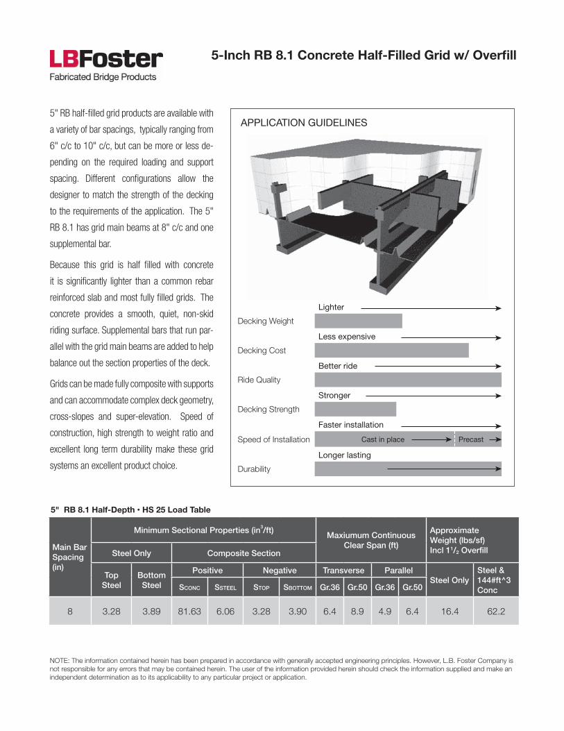
5" RB half-filled grid products are available with
a variety of bar spacings, typically ranging from
6" c/c to 10" c/c, but can be more or less de-
pending on the required loading and support
spacing. Different configurations allow the
designer to match the strength of the decking
to the requirements of the application. The 5"
RB 8.1 has grid main beams at 8" c/c and one
supplemental bar.
Because this grid is half filled with concrete
it is significantly lighter than a common rebar
reinforced slab and most fully filled grids. The
concrete provides a smooth, quiet, non-skid
riding surface. Supplemental bars that run par-
allel with the grid main beams are added to help
balance out the section properties of the deck.
Grids can be made fully composite with supports
and can accommodate complex deck geometry,
cross-slopes and super-elevation. Speed of
construction, high strength to weight ratio and
excellent long term durability make these grid
systems an excellent product choice.
5-Inch RB 8.1 Concrete Half-Filled Grid w/ Overfill
APPLICATION GUIDELINES
5" RB 8.1 Half-Depth • HS 25 Load Table
Main Bar Spacing (in)
Minimum Sectional Properties (in3/ft)Maxiumum Continuous
Clear Span (ft)
Approximate Weight (lbs/sf)Incl 11/2 OverfillSteel Only Composite Section
Top Steel
Bottom Steel
Positive Negative Transverse ParallelSteel Only
Steel & 144#ft^3 ConcSconc SSteel Stop Sbottom Gr.36 Gr.50 Gr.36 Gr.50
8 3.28 3.89 81.63 6.06 3.28 3.90 6.4 8.9 4.9 6.4 16.4 62.2
Main Beam (MB) @ 8" c/c 5 3/16" deep x 5.6 #/LF special rolled beam
Cross Bar (C’Bar) @ 4" or 8" c/c 2" x 1/4" flat bar
Supplemental Bar (1 between each MB) 1" x 1/4" (minimum) flat bar
Steel SpecificationAll steel shall be 50 ksi (A709 Gr. 50 / A572) or 50 ksi weathering (A709 Gr. 50W / A588)
Typical SpecificationThe steel grid bridge flooring shall be 5-Inch RB 8.1 Half-Filled as manufactured by the L.B. Foster Company, 1016 Greentree Road, Pittsburgh, Pennsylvania 15220 – Phone (412) 928-3452 & Fax (412) 928-3514. The deck shall be manufactured from the following steel elements:
The decking shall consist of panels fabricated in maximum standard widths of 8'-2". Narrower units shall be furnished when required at slab end, transverse joints, or along edges of slabs adjacent to curbs. The deck shall be assembled such that the tops of all elements are in the same plane and notching of the main bar top flange shall not be permitted.
The grid shall be welded using the manufacturers standard welding process.
Finish: Most types of coatings can be provided; common finishes are mill finish (for 50 ksi weathering steel) and hot dipped galvanized for 50 ksi steel-note that distortion from galvanizing will occur, request manufacturer’s tolerances.
Telephone: 412.928.3452 • Fax: 412.928.3514 • www.lbfoster.com
5-Inch RB 8.1 Concrete Half-Filled Grid w/ Overfill
Request manufacturer’s standard 4 part product specification for inclusion with project documents.
Lighter
Decking Weight
Less expensive
Decking Cost
Better ride
Ride Quality
Stronger
Decking Strength
Faster installation
Speed of Installation Cast in place Precast
Longer lasting
Durability
NOTE: The information contained herein has been prepared in accordance with generally accepted engineering principles. However, L.B. Foster Company is not responsible for any errors that may be contained herein. The user of the information provided herein should check the information supplied and make an independent determination as to its applicability to any particular project or application.
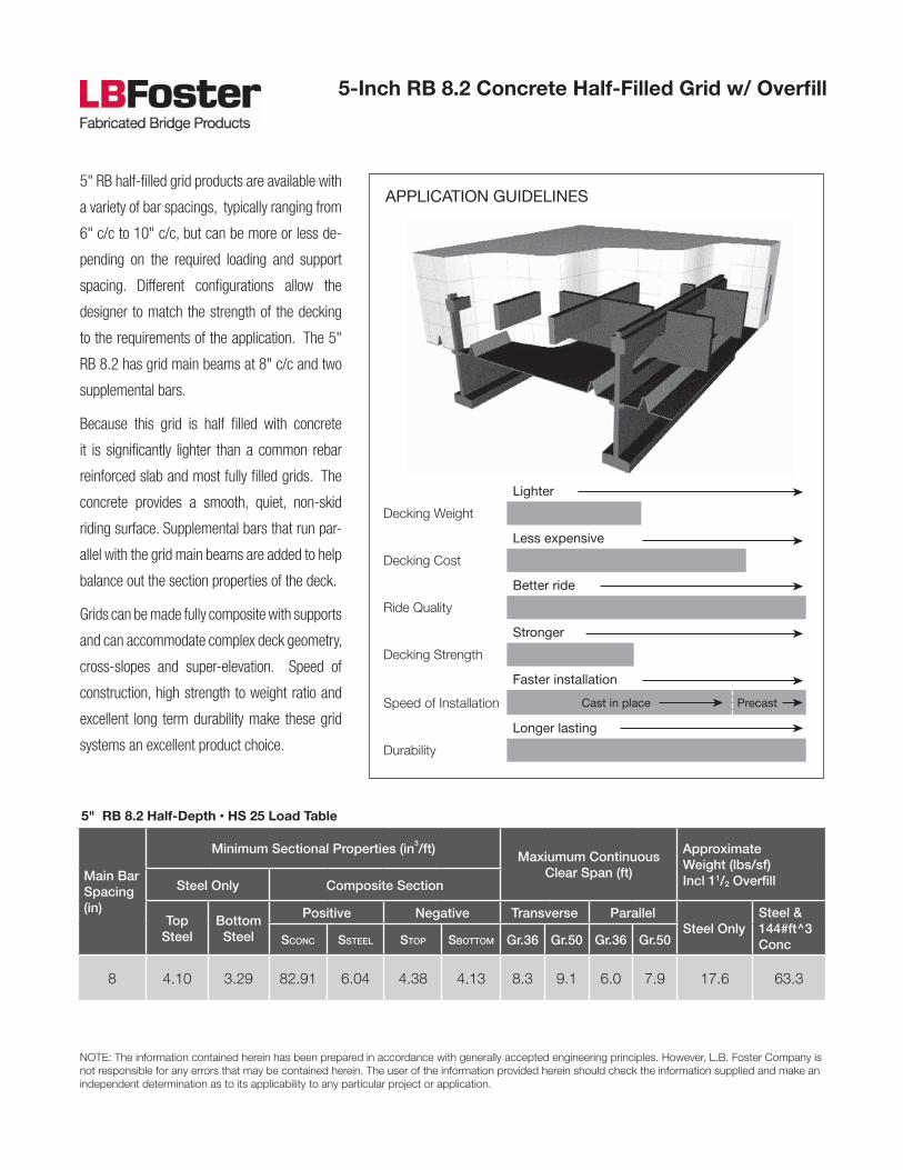
5" RB half-filled grid products are available with
a variety of bar spacings, typically ranging from
6" c/c to 10" c/c, but can be more or less de-
pending on the required loading and support
spacing. Different configurations allow the
designer to match the strength of the decking
to the requirements of the application. The 5"
RB 8.2 has grid main beams at 8" c/c and two
supplemental bars.
Because this grid is half filled with concrete
it is significantly lighter than a common rebar
reinforced slab and most fully filled grids. The
concrete provides a smooth, quiet, non-skid
riding surface. Supplemental bars that run par-
allel with the grid main beams are added to help
balance out the section properties of the deck.
Grids can be made fully composite with supports
and can accommodate complex deck geometry,
cross-slopes and super-elevation. Speed of
construction, high strength to weight ratio and
excellent long term durability make these grid
systems an excellent product choice.
5-Inch RB 8.2 Concrete Half-Filled Grid w/ Overfill
APPLICATION GUIDELINES
5" RB 8.2 Half-Depth • HS 25 Load Table
Main Bar Spacing (in)
Minimum Sectional Properties (in3/ft)Maxiumum Continuous
Clear Span (ft)
Approximate Weight (lbs/sf)Incl 11/2 OverfillSteel Only Composite Section
Top Steel
Bottom Steel
Positive Negative Transverse ParallelSteel Only
Steel & 144#ft^3 ConcSconc SSteel Stop Sbottom Gr.36 Gr.50 Gr.36 Gr.50
8 4.10 3.29 82.91 6.04 4.38 4.13 8.3 9.1 6.0 7.9 17.6 63.3
Main Beam (MB) @ 8" c/c 5 3/16" deep special rolled beam x 5.6#/LF
Cross Bar (C’Bar) @ 4" or 8" c/c 2" x 1/4" flat bar
Supplemental Bar (1 between each MB) @ 8" c/c 1" x 1/4" (minimum) flat bar
Steel SpecificationAll steel shall be 50 ksi (A709 Gr. 50 / A572) or 50 ksi weathering (A709 Gr. 50W / A588)
Typical Specification
The decking shall consist of panels fabricated in maximum standard widths of 8'-2". Narrower units shall be furnished when required at slab end, transverse joints, or along edges of slabs adjacent to curbs. The deck shall be assembled such that the tops of all elements are in the same plane and notching of the main bar top flange shall not be permitted.
The grid shall be welded using the manufacturers standard welding process.
Finish: Most types of coatings can be provided; common finishes are mill finish (for 50 ksi weathering steel) and hot dipped galvanized for 50 ksi steel-note that distortion from galvanizing will occur, request manufacturer’s tolerances.
Telephone: 412.928.3452 • Fax: 412.928.3514 • www.lbfoster.com
Typical Details: 5-Inch RB 8.2 Half-Filled
The welded open steel grid bridge flooring shall be 5-Inch RB 8.2 Half-Filled as manufactured by the L.B. Foster Company, 1016 Greentree Road, Pittsburgh, Pennsylvania 15220 – Phone (412) 928-3452 & Fax (412) 928-3514. The deck shall be manufactured from the following steel elements:
Request manufacturer’s standard 4 part product specification for inclusion with project documents.
Lighter
Decking Weight
Less expensive
Decking Cost
Better ride
Ride Quality
Stronger
Decking Strength
Faster installation
Speed of Installation Cast in place Precast
Longer lasting
Durability
NOTE: The information contained herein has been prepared in accordance with generally accepted engineering principles. However, L.B. Foster Company is not responsible for any errors that may be contained herein. The user of the information provided herein should check the information supplied and make an independent determination as to its applicability to any particular project or application.
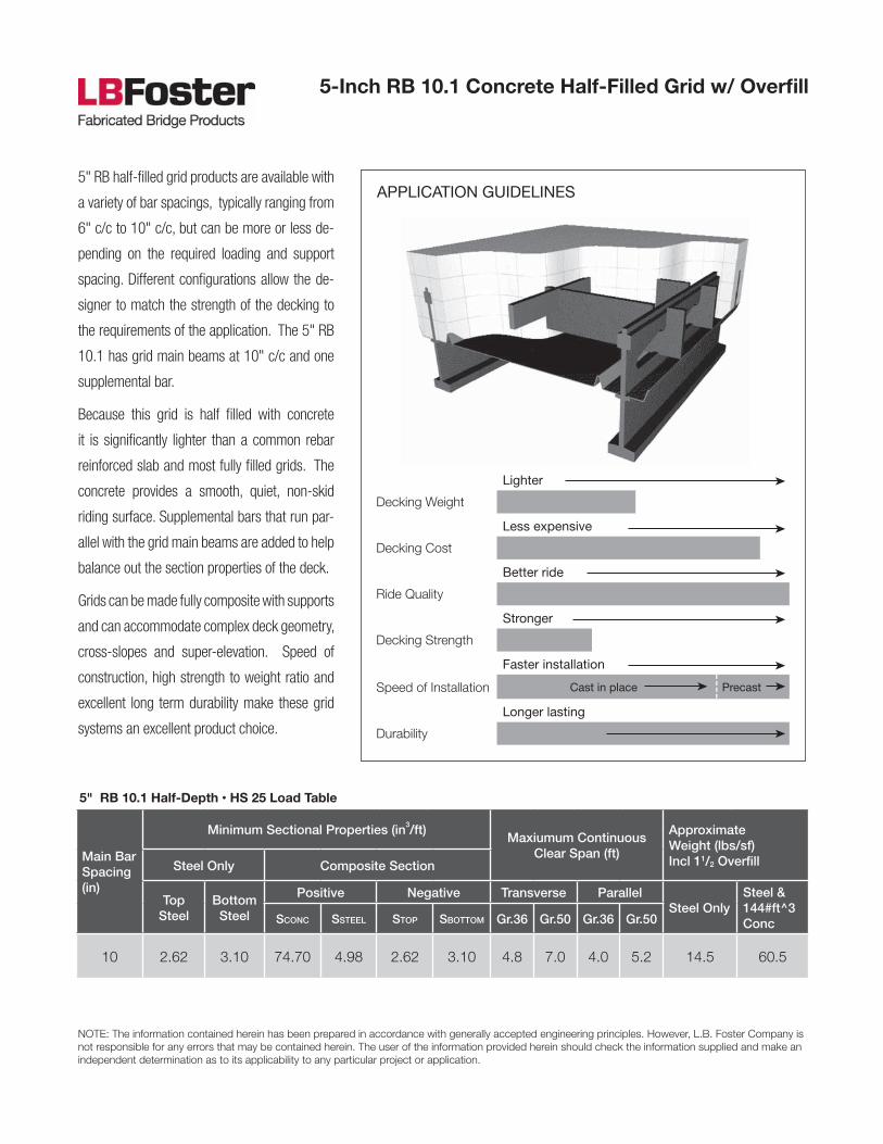
5" RB half-filled grid products are available with
a variety of bar spacings, typically ranging from
6" c/c to 10" c/c, but can be more or less de-
pending on the required loading and support
spacing. Different configurations allow the de-
signer to match the strength of the decking to
the requirements of the application. The 5" RB
10.1 has grid main beams at 10" c/c and one
supplemental bar.
Because this grid is half filled with concrete
it is significantly lighter than a common rebar
reinforced slab and most fully filled grids. The
concrete provides a smooth, quiet, non-skid
riding surface. Supplemental bars that run par-
allel with the grid main beams are added to help
balance out the section properties of the deck.
Grids can be made fully composite with supports
and can accommodate complex deck geometry,
cross-slopes and super-elevation. Speed of
construction, high strength to weight ratio and
excellent long term durability make these grid
systems an excellent product choice.
5-Inch RB 10.1 Concrete Half-Filled Grid w/ Overfill
APPLICATION GUIDELINES
5" RB 10.1 Half-Depth • HS 25 Load Table
Main Bar Spacing (in)
Minimum Sectional Properties (in3/ft)Maxiumum Continuous
Clear Span (ft)
Approximate Weight (lbs/sf)Incl 11/2 OverfillSteel Only Composite Section
Top Steel
Bottom Steel
Positive Negative Transverse ParallelSteel Only
Steel & 144#ft^3 ConcSconc SSteel Stop Sbottom Gr.36 Gr.50 Gr.36 Gr.50
10 2.62 3.10 74.70 4.98 2.62 3.10 4.8 7.0 4.0 5.2 14.5 60.5

Main Beam (MB) @ 10" c/c 5 3/16" deep special rolled beam x 5.6 #/LF
Cross Bar (C’Bar) @ 4" or 8" c/c 2" x 1/4" flat bar
Supplemental Bar (1 between each MB) 1" x 1/4" (minimum) flat bar
Steel SpecificationAll steel shall be 50 ksi (A709 Gr. 50 / A572) or 50 ksi weathering (A709 Gr. 50W / A588)
Typical SpecificationThe steel grid bridge flooring shall be 5-Inch RB 10.1 Half-Filled as manufactured by the L.B. Foster Company, 1016 Greentree Road, Pittsburgh, Pennsylvania 15220 – Phone (412) 928-3452 & Fax (412) 928-3514. The deck shall be manufactured from the following steel elements:
The decking shall consist of panels fabricated in maximum standard widths of 8'-4". Narrower units shall be furnished when required at slab end, transverse joints, or along edges of slabs adjacent to curbs. The deck shall be assembled such that the tops of all elements are in the same plane and notching of the main bar top flange shall not be permitted.
The grid shall be welded using the manufacturers standard welding process.
Finish: Most types of coatings can be provided; common finishes are mill finish (for 50 ksi weathering steel) and hot dipped galvanized for 50 ksi steel-note that distortion from galvanizing will occur, request manufacturer’s tolerances.
Telephone: 412.928.3452 • Fax: 412.928.3514 • www.lbfoster.com
5-Inch RB 10.1 Concrete Half-Filled Grid w/ Overfill
Request manufacturer’s standard 4 part product specification for inclusion with project documents.

Lighter
Decking Weight
Less expensive
Decking Cost
Better ride
Ride Quality
Stronger
Decking Strength
Faster installation
Speed of Installation Cast in place Precast
Longer lasting
Durability
NOTE: The information contained herein has been prepared in accordance with generally accepted engineering principles. However, L.B. Foster Company is not responsible for any errors that may be contained herein. The user of the information provided herein should check the information supplied and make an independent determination as to its applicability to any particular project or application.
L. B. Foster’s 5-Inch RB 10.2 Half-Filled w/
Overfill 5" RB half-filled grid products are
available with a variety of bar spacings, typically
ranging from 6" c/c to 10" c/c, but can be more
or less depending on the required loading and
support spacing. Different configurations allow
the designer to match the strength of the
decking to the requirements of the application.
The 5" RB 10.2 has grid main beams at 10" c/c
and two supplemental bars.
Because this grid is half filled with concrete it
is significantly lighter than a common rebar
reinforced slab and most fully filled grids. The
concrete provides a smooth, quiet, non-skid riding
surface. Supplemental bars that run parallel with
the grid main beams are added to help balance
out the section properties of the deck.
Grids can be made fully composite with supports
and can accommodate complex deck geometry,
cross-slopes and super-elevation. Speed of
construction, high strength to weight ratio and
excellent long term durability make these grid
systems an excellent product choice.
5-Inch RB 10.2 Concrete Half-Filled Grid w/ Overfill
APPLICATION GUIDELINES
5" RB 10.2 Half-Depth • HS 25 Load Table
Main Bar Spacing (in)
Minimum Sectional Properties (in3/ft)Maxiumum Continuous
Clear Span (ft)
Approximate Weight (lbs/sf)Incl 11/2 OverfillSteel Only Composite Section
Top Steel
Bottom Steel
Positive Negative Transverse ParallelSteel Only
Steel & 144#ft^3 ConcSconc SSteel Stop Sbottom Gr.36 Gr.50 Gr.36 Gr.50
10 3.50 3.28 75.42 4.97 3.50 3.30 6.4 8.4 4.9 6.4 15.5 61.4

Main Beam (MB) @ 10" c/c 5 3/16" deep special rolled beam x 5.6 #/LF
Cross Bar (C’Bar) @ 4" or 8" c/c 2" x 1/4" flat bar
Supplemental Bar (2 between each MB) 1" x 1/4" (minimum) flat bar
Steel SpecificationAll steel shall be 50 ksi (A709 Gr. 50 / A572) or 50 ksi weathering (A709 Gr. 50W / A588)
Typical SpecificationThe steel grid bridge flooring shall be 5-Inch RB 10.2 Half-Filled as manufactured by the L.B. Foster Company, 1016 Greentree Road, Pittsburgh, Pennsylvania 15220 – Phone (412) 928-3452 & Fax (412) 928-3514. The deck shall be manufactured from the following steel elements:
The decking shall consist of panels fabricated in maximum standard widths of 8'-4". Narrower units shall be furnished when required at slab end, transverse joints, or along edges of slabs adjacent to curbs. The deck shall be assembled such that the tops of all elements are in the same plane and notching of the main bar top flange shall not be permitted.
The grid shall be welded using the manufacturers standard welding process.
Finish: Most types of coatings can be provided; common finishes are mill finish (for 50 ksi weathering steel) and hot dipped galvanized for 50 ksi steel-note that distortion from galvanizing will occur, request manufacturer’s tolerances.
Telephone: 412.928.3452 • Fax: 412.928.3514 • www.lbfoster.com
5-Inch RB 10.2 Concrete Half-Filled Grid w/ Overfill
Request manufacturer’s standard 4 part product specification for inclusion with project documents.

The information contained herein has been prepared in acordance with generally accepted engineering principles. However, L. B. Foster is not responsible for any errors that may be contained herein. The user of the information provided herein should check the information supplied and make an independent determination as to its applicability to any particular project or application.
The 6.5” Half-Depth grid reinforced concrete
bridge decking is the latest design innovation
from L.B. Foster. The increased decking depth
offers improved stiffness for longer spans.
Important changes in the grid construction have
helped to make this grid cost competitive with
alternative deck types while still offering the
advantages of higher strength-to-weight ratio,
better durability and faster installation time.
Because this grid is filled half-depth with
concrete it has a much higher strength-to-
weight ratio than a common rebar reinforced
slab. The half-depth concrete in the grid drops
down to full depth at the supports and is
typically attached with headed shear studs for
full composite action.
This grid style requires the use of a concrete
overfill which is the amount of concrete
poured over the top of the steel grid. As with
all grid reinforced concrete bridge decking, the
concrete overfill provides increased stiffness,
added corrosion protection for the steel and a
smooth riding surface that can be resurfaced, as
required, with standard resurfacing techniques.
6.5 inch RB Half Depth
APPLICATION GUIDELINES
6.5 inch RB Half Depth • HS 25 Load Table
Main Bar Spacing (in)
Minimum Sectional Properties (in3/ft)Maxiumum Continuous Clear
Span (ft)Approximate Weight (lbs/sf)
Steel Only Composite Section
Top Steel
Bottom Steel
Positive Negative Transverse or Parallel Steel OnlySteel & 144#ft^3 Conc
6 13.9087 13.6836 183.2325 13.7386 17.1 28.3 86.3
8 10.4315 10.2627 160.827 10.3039 15.4 22.4 80.9
10 8.3452 8.2101 145.9349 8.2431 14.1 18.9 77.7
12 6.9543 6.8418 135.1171 6.8693 13.2 17.2 75.6
Lighter
Decking Weight
Less expensive
Decking Cost
Better ride
Ride Quality
Stronger
Decking Strength
Faster installation
Speed of Installation Cast in place Precast
Longer lasting
Durability

Main Beam (MB) 6 1/2" deep special rolled beam x 8.9 #/LF
Cross Bar (C’Bar) @ 5" c/c 2" x 1/4" flat bar & #6 Rebar - Alternating
Supplemental Bar (2 between each MB) #6 Rebar
Steel SpecificationSteel shall be 50 ksi (A709 Gr. 50 / A572) or 50 ksi weathering (A709 Gr. 50W / A588) Rebar to be ASTM A-615 Gr.60
Typical SpecificationThe steel grid bridge flooring shall be 6.5 inch RB Half Depth as manufactured by the L.B. Foster Company, 1016 Greentree Road, Pittsburgh, Pennsylvania 15220 – Phone (412) 928-3452 & Fax (412) 928-3514. The deck shall be manufactured from the following steel elements:
Telephone: 412.928.3452 • Fax: 412.928.3514 • www.lbfoster.com
6.5 inch RB Half Depth
Request manufacturer’s standard 4-part product specification for inclusion with your project documents.
L. B. FOSTER, CO.GENERAL OFFICES
PITTSBURGH, PENNSYLVANIA 15220
SYSTEM: 6-1/2" RB HALF-FILLED GRID DECK
A
B
SECTION A-A
SEC
TIO
N B
-B
A
B
* 2"
20 GAUGEFORM PAN
1/8"
(±1/8")
1/4" GAP
(±1/4")
2" x 1/4"CROSS BAR
#6REBAR
6", 8", 10", 12" c/c
("S")
"S"/2 MAX.
1 1/2" MIN.
SPLICECL.
SPLICECL.
8'-0" STANDARD WIDTH OF ONE GRID UNIT
(7'-6" FOR 10" c/c)
2" M
INIM
UM
REC
OM
MEN
DED
OV
ERFI
LL
* 6
1/2"
OPTIONAL END TRIM BAR ATCUSTOMER REQUEST FLUSHWITH CONCRETE OVERFILL.
10"
c/c
#6 R
EBA
RS
10"
c/c
CR
OSS
BA
RS
ROTATE CROSSBAR INTOPOSITION
10"
c/c
#6 N
ON
-WEL
DED
REB
AR
SPLI
CE
6 1/2" RIBBEDMAIN BAR
CROSSBAR#6
REBAR
6 1/2" RIBBEDMAIN BAR
NOTES:1. MANUFACTURER RESERVES THE RIGHT TO MAKE MINOR CHANGES FOR PRODUCT IMPROVEMENT.
2. FOR A "CAST IN PLACE" SYSTEM, L. B. FOSTER RECOMMENDS THE "NON-WELDED REBAR SPLICE" AS THE PREFERRED JOINT CONNECTION. CONTACT L. B. FOSTER FOR ALTERNATE JOINT CONNECTIONS.
* SUBJECT TO MILL TOLERANCES.
3/16
"S"/3 "S"/3 "S"/3
10"
c/c
#4 N
ON
-WEL
DED
REB
AR
SPLI
CE