5. gating design and analysis - tripod.combravi11.tripod.com/cdach5.pdf · 5. gating design and...
TRANSCRIPT

57
5 . Gat ing Des ign and Analys is On the timeline of a cast product, mold filling is a mere dot. Yet, it has the greatest influence on casting quality, both internal and external. The flow of molten metal after being poured is a transient phenomenon which is accompanied by turbulence, splashing, separation of streams near change of sections, branching off and rejoining of streams, changes in melt properties such as density, viscosity and surface tension and the onset of solidification. In this chapter, we describe the objectives and types of gating systems, followed by a systematic procedure for their location, design, analysis, optimization and validation. 5.1 Mold Fil l ing Phenomenon Let us review two major characteristics of molten metal related to mold filling – fluidity and turbulence, and see how they are related to flow related defects. Fluidity is not a physical property. It is a technological characteristic. It indicates the ability of liquid metal to flow through a given mold passage – even as it is solidifying – and fill the cavity to reproduce the design details. It is quantified in terms of the solidified length of a standard spiral casting. The fluidity as defined by the foundry community is different that defined by physicists (as the reciprocal of viscosity). The casting fluidity is driven by metallostatic pressure and hindered by: viscosity and surface tension of molten metal, heat diffusivity of mold, back pressure of air in mold cavity and friction between the metal-mold pair. Metallostatic head: The metallostatic pressure is given by ñ g h where ñ is the metal density and h is the height of liquid metal column above the filling point. A higher metallostatic pressure gives higher velocity of molten metal, and thereby higher fluidity. Viscosity: Viscosity depends on the metal family, composition and the instantaneous temperature. For most metals, the viscosity at the pouring temperature is close to that of water (1 centistoke); aluminum: 1.2 and iron: 0.9 centistokes. In comparison, the viscosity of typical mineral oils is about 600. Surface tension: For a flat plate of thickness t, the relation between head, thickness and surface tension is given by: ñ g h = ã / t, where ã is the surface tension. At the pouring temperature, the surface tension of aluminum and iron is 0.5 and 0.9 N/m respectively; similar to mercury at room temperature (0.46 N/m), but higher than water (0.07 N/m).

58
Heat diffusivity: Molds with high heat diffusivity transfer heat faster from the molten metal, causing it to freeze earlier and stop flowing. It is given by • (Km ñm Cm), where Km is thermal conductivity, ñm is density and Cm is specific heat of the mold material. Back Pressure: As molten metal advances in the mold, the back pressure of air that is being compressed in the cavity ahead effectively reduces the metallostatic pressure, and thus hinders filling. The back pressure depends on the cavity volume, mold permeability and the velocity of the advancing front. Venting helps. Friction: The rough surface of sand mold hinders metal flow. Thus mold coating (usually water based, containing silica flour and graphite) reduces the friction between the metal and mold, contributing to higher fluidity. In general, fluidity of pure metals is higher than alloys. Within alloys, eutectics have higher fluidity than non-eutectics. The fluidity of grey iron ranges between 0.5-1.0 m, and can be estimated by the empirical equation:
Fluidity = 14.9 CE + 0.05 Tp - 155 inch Where CE is the carbon equivalent given by CE = %C + 0.25 %Si + 0.5 %P and Tp is the pouring temperature in Fahrenheit. Turbulence implies irregular, fluctuating flow with disturbances. It is observed when: (1) inertia forces (which make the fluid continue in the same direction), are much higher than the drag forces (which tend to stop the fluid motion), and (2) there are obstructions in the path of flow, such as a sharp corner or a change of section thickness. The drag forces include those caused by viscosity and surface tension. The viscous forces mainly operate in the bulk of the liquid metal, whereas surface tension forces operate near the mold wall. Thus we have two types of turbulence: bulk and surface. Bulk turbulence is quantified by Reynolds number Re, which is the ratio of inertia to viscous pressure in a fluid. It is given by ñ V d / ì where ñ is the density, ì is the viscosity and V is the velocity of the liquid; d is a characteristic dimension of the flow path. If Re is more than 2000, then the flow is usually turbulent. Surface turbulence is quantified by the Weber number We, which is the ratio of inertia to surface tension pressure in a fluid. It is given by ñ V2 r / ã where r is the radius of curvature of the free liquid surface. For We is less than 1, surface turbulence is absent. When it is 100 or more, surface turbulence is prominent, leading to violent mixing of surface layers with the bulk of the molten metal. The path of molten metal during casting process comprises mainly four parts: 1. Pouring of molten metal from ladle to the cup in the mold 2. Flow within the gating channels, from pouring basin to ingate

59
3. Jet of molten metal emerging from ingate and entering the mold cavity 4. Filling of mold cavity by liquid movements in the bulk as well as near the surface. In general, the entire path of molten metal, within the gating system as well as the mold cavity, is turbulent in most castings. This can be readily ascertained by calculating the value of Reynolds number for a typical casting. A major purpose of the gating system (instead of pouring metal directly into the mold cavity) is to reduce the turbulence, though it cannot be completely eliminated. There are mainly three major classes of casting defects related to mold filling: incomplete filling, solid inclusions and gaseous entrapments (Fig.4.1).
Fig.4.1: Filling related defects. Top left - cold shut, right - misrun.
Bottom left - blow hole, right - sand and slag inclusions. [Source: Atlas of Casting Defects, Institute of British Foundrymen]
Incomplete filling: This is primarily caused by poor fluidity of molten metal, and manifests in the form of a cold shut or misrun. A cold shut occurs when two streams of molten metal coming from opposite directions meet, but do not fuse completely. A misrun occurs when the molten metal does not completely fill a section of the mold cavity (usually an end section far from the entry point). The presence of surface oxides and impurities on the advancing front of liquid metal aggravates such defects. Solid inclusions: This is primarily caused by the turbulence in molten metal, and manifests in the form of sand inclusion or slag inclusion. Sand inclusions are mainly caused by bulk turbulence in gating channels or mold cavity, which dislodges sand

60
particles from the mold wall. Slag inclusions can be caused by surface turbulence anywhere along the path of molten metal, leading to mixing of surface oxide layers with the rest of molten metal. Gaseous entrapments: This class of casting defects includes air and gas entrapment, usually in form of blow hole and gas porosity, respectively. They occur when the air or gas inside the mold cavity cannot escape through the mold. The major source of gases includes dissolved gases in the molten metal, vaporization of mold sand moisture and combustion of binders in core or mold sand. The occurrence of these defects increases when the amount of air entrapped or gas generated is high, filling and solidification of molten metal are fast, the venting of the mold is poor.
5.2 Gating S ys tem and T ypes A mold cavity must be filled with clean metal in a smooth, controlled, uniform and complete manner, for the casting to be free of discontinuities, solid inclusions and voids. This can be achieved by a well-designed gating system. The first step involves selecting the type of gating system and the layout of gating channels: the orientation and position of sprue, runner and ingate(s). The most critical design decision is the ideal filling time, based on which the gating channels are designed. The main objective of a gating system is to lead clean molten metal poured from ladle to the casting cavity, ensuring smooth, uniform and complete filling. Clean metal implies preventing the entry of slag and inclusions into the mold cavity, and minimizing surface turbulence. Smooth filling implies minimizing bulk turbulence. Uniform filling implies that all portions of the casting fill in a controlled manner, usually at the same time. Complete filling implies leading molten metal to thin and end sections with minimum resistance.
Fig.4.2: Major elements of a gating system
61
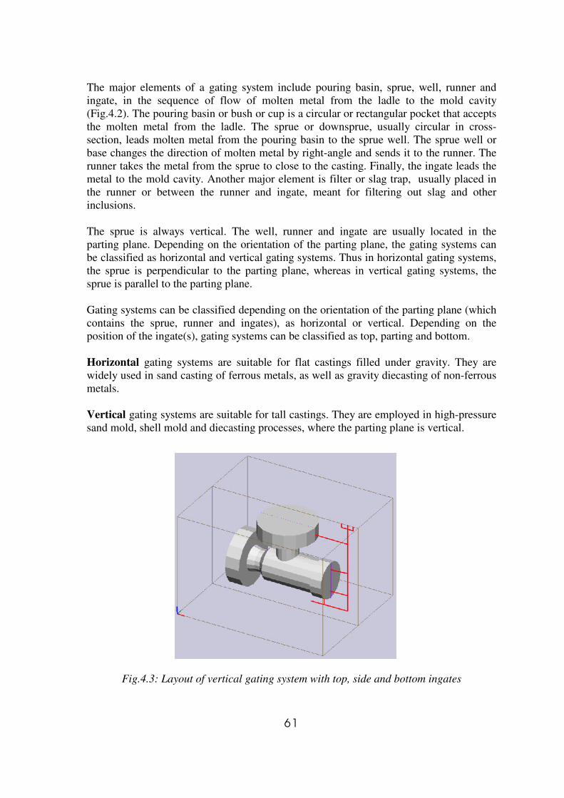
The major elements of a gating system include pouring basin, sprue, well, runner and ingate, in the sequence of flow of molten metal from the ladle to the mold cavity (Fig.4.2). The pouring basin or bush or cup is a circular or rectangular pocket that accepts the molten metal from the ladle. The sprue or downsprue, usually circular in cross-section, leads molten metal from the pouring basin to the sprue well. The sprue well or base changes the direction of molten metal by right-angle and sends it to the runner. The runner takes the metal from the sprue to close to the casting. Finally, the ingate leads the metal to the mold cavity. Another major element is filter or slag trap, usually placed in the runner or between the runner and ingate, meant for filtering out slag and other inclusions. The sprue is always vertical. The well, runner and ingate are usually located in the parting plane. Depending on the orientation of the parting plane, the gating systems can be classified as horizontal and vertical gating systems. Thus in horizontal gating systems, the sprue is perpendicular to the parting plane, whereas in vertical gating systems, the sprue is parallel to the parting plane. Gating systems can be classified depending on the orientation of the parting plane (which contains the sprue, runner and ingates), as horizontal or vertical. Depending on the position of the ingate(s), gating systems can be classified as top, parting and bottom. Horizontal gating systems are suitable for flat castings filled under gravity. They are widely used in sand casting of ferrous metals, as well as gravity diecasting of non-ferrous metals. Vertical gating systems are suitable for tall castings. They are employed in high-pressure sand mold, shell mold and diecasting processes, where the parting plane is vertical.
Fig.4.3: Layout of vertical gating system with top, side and bottom ingates

62
Top gating systems, in which hot molten metal enters at the top of the casting, promote directional solidification from bottom to top of the casting. These are however, suitable only for flat castings to limit the damage to metal as well as the mold by free fall of the molten metal during initial filling. Bottom gating systems have the opposite characteristics: the metal enters at the bottom of the casting and gradually fills up the mold with minimal disturbances. It is recommended for tall castings, where free fall of molten metal (from top or parting gates) has to be avoided. Middle or side or parting gating systems combine the characteristics of top and bottom gating systems. If the gating channels are at the parting plane, they are also easier to produce and modify if necessary, during trial runs. The most widely used system is the horizontal gating with ingates at the parting plane. In vertical gating systems, ingates may be positioned at top, bottom and side.
5.3 Gating Channel Layout The most important decision here is the number and location of ingate(s). Let us consider horizontal gating systems with side ingates. Their location is governed by the following considerations (Fig.4.4).
Fig.4.4 Heuristics for ingate location 1. Side feeders: If side feeders are employed, then their efficiency can be improved by filling with the first stream of hot molten metal through ingates. It also reduces the fettling effort and the resulting marks on the casting, since the ingates do not have to be removed separately.

63
2. Thick sections: The next best position after a side feeder is a thick section, which will allow molten metal to flow to other sections with minimal cooling. It will also reduce occasional breakage during fettling of ingates. 3. Clear path: In sand casting, the molten metal should be allowed to flow with minimal obstructions and change of direction (particularly at sharp corners) to avoid turbulence-related problems. Ingates should never be placed directly opposite a core. 4. Low free fall: The ingate should be located where the free fall of molten metal inside the mold cavity is low. This minimizes oxidation during fall and erosion at the point of impact of molten metal. The number of ingates must be sufficient enough, so that the distance of flow from any ingate to the farthest point filled by that ingate is less than the fluidity distance. The sprue conducts the molten metal from the pouring basin at its top to the plane in which the runners and ingates are located. Its location is governed by the following considerations: 1. Flow distance: The sprue location must minimize the total flow distance within the gating channels, to reduce heat loss as well as maximize yield. 2. Heat concentration: Since the hottest metal flows through the sprue, it must be away from hot spots (essentially thick sections) in the casting. 3. Mold layout: The sprue must be located to minimize the size of the bounding box enclosing the entire casting (including the gating channels), so that a smaller mold is required. This also applies to multi cavity layout, where the sprue and runner(s) are shared by multiple cavities. The runner layout is simply given by the shortest path to connect the ingates with sprue. 5.4 Optimal Fil l ing T ime A casting that fills too slow can have discontinuities such as cold shuts and misruns. Too fast filling can lead to solid and gaseous inclusions. The higher limit of filling time (slowest filling) is governed by the need to avoid premature freezing in thin sections before complete filling. The lower limit of the filling time (fastest filling) is governed by the onset of surface turbulence. The correct filling time lies somewhere in between, and is a function of cast metal, weight, minimum section thickness and pouring temperature. Several empirical equations for determining the correct filling time for major metals have been developed by casting researchers, based on experimental investigations. The filling
64
time τf is expressed as a function of casting weight W in kg, section thickness t in mm and fluidity length Lf in mm. A generalized equation for filling time can be written as:
τf = K0 (Kf Lf / 1000 ) ( Ks + Kt t / 20 ) ( Kw W )P
There are five coefficients: K0 is an overall coefficient, and Kf , Ks , Kt , Kw are the coefficients for fluidity, size, thickness and weight, respectively. For grey iron the following values may be used: K0 = 1.0, Kf = 1.0, Ks = 1.1 (for castings of size 100-1000 mm), Kt = 1.4 (for wall thickness up to 10 mm), Kw = 1 and P = 0.4. Based on individual experience, an expert casting engineer can set the values of the coefficients for each metal-process combination. These form a valuable part of the knowledge base of a foundry specializing in specific castings. Metal velocity: The optimal filling time is determined such that gating channels can be designed to avoid surface turbulence and minimize bulk turbulence within the gating channels as well as the mold cavity. This mainly depends on the velocity of the molten metal, which varies widely within the gating channels as well as inside the mold cavity. For a given location in the casting, the velocity also changes with time, from the start to end of filling. The most important event is that of molten metal emerging from the ingate, just after the filling of gating channels and before the filling of mold cavity. The metal is both hot and fast at this location and instant, and can lead to considerable damage if not controlled properly. The velocity of molten metal at the ingate depends on mainly two parameters: (1) the metallostatic head and (2) the ratio of cross-sections of sprue exit, runner(s) and ingates(s), referred to as the gating ratio. In general, the velocity of molten metal must be kept lower than 1 m/s for ferrous metals and 0.5 m/s for aluminum alloys. Gating Ratio: It is given by As:Ar:Ag where As , Ar , Ag are the cross-sectional areas of sprue exit, runner(s) and ingate(s). If multiple runners and ingates are present, the total area (of all runners, or all ingates, respectively) must be considered. A converging-diverging system, where the ingate area is more than the sprue exit area, is to be preferred. This ensures that the metal slows down (thereby reducing turbulence-related problems). Examples of such gating ratios include: 1:2:1.5 for ferrous and 1:4:4 for non-ferrous metals. Higher values of ingate area may be used (such as 1:4:8) to further reduce the velocity of molten metal through the ingates to within the recommended range, as long as flow separation (and thereby air aspiration) is avoided. 5.5 Gating Element Des ign The gating system can be designed to fill a given casting in a predetermined time, by keeping a constant level of liquid metal in the pouring basin during pouring, to achieve a controlled rate of flow through the choke. The choke is the smallest cross-section in the gating system that controls the flow rate of molten metal. The element (sprue exit, runners or ingates) with the smallest value in the gating ratio is considered the choke. The choke area Ac is given by:
Ac = W / ( ñc τf Vc )

65
Where, W is the total casting weight (including feeders and gating channels), ñc is the metal density, τf is the total filling time and Vc is the choke velocity. The choke velocity is given by: Vc = Vp + cf • (2 g H) where H is the metallostatic pressure head, given by the vertical distance between the liquid level in pouring cup and the centerline of the choke. The value of pouring velocity Vp is non-zero, if poured from a height or if bottom pouring ladles are used. The friction factor cf within the gating system depends on its geometry and surface finish, and ranges between 0.6-0.9. Note that the weight of the gating system is unknown at the time of calculating the mold filling time and choke area. This can be overcome by determining the total casting weight after gating design and repeating the calculations. During actual filling, the metallostatic pressure head gradually decreases after the molten metal starts rising above the level of choke. Thus the average value of actual choke velocity is less than the one used above, leading to slower filling. This can be compensated by estimating the actual filling time (as described in a later section), and then correcting the choke area.
Fig.4.5: Flow chart of gating element design
The cross-sectional area of sprue exit, runners and ingates, is initially determined based on the choke area, gating ratio and the number of individual elements. Then the sectional area of individual elements, as well as their shape and dimensions are determined as follows. Sprue: It usually has a circular cross-section, which minimizes turbulence and heat loss. The cross-sectional area at the sprue exit or bottom is calculated from the choke area and
66
gating ratio. The area of the sprue top should be calculated using mass and energy balance equations, to prevent flow separation in the sprue. Essentially,
A1 • H1 = A2 • H2 Where, H1 and H2 are the metallostatic pressure head at the top and bottom of the sprue, respectively; A1 and A2 being the respective cross-sectional areas. The ideal sprue must be larger at the top and smaller at the bottom. Since this leads to an undercut, such a sprue can not be created by the pattern during molding operations, and must be formed by a core. If this is not economical, then the choke can be created in the beginning of runner. Sprue well: It arrests the free fall of molten metal through the sprue and turns it by a right angle towards the runner. It must be designed to minimize turbulence and air aspiration. The recommended shape of a sprue well is cylindrical, with diameter twice that of sprue exit and depth twice that of runner. A fillet between the well and runner will facilitate smooth transfer of molten metal. Runner: The main function of the runner is to slow down the molten metal, which speeds up during its free fall through the sprue, and take it to all the ingates. This implies that the total cross-sectional area of runner(s) must be greater than the sprue exit. In general, a ratio of 1:2 is recommended. A much higher ratio (such as 1:4) may lead to flow separation in the runner. The second implication is that the runner must fill completely before letting the molten metal enter the ingates. Finally, in casting where more than one ingate is present, the runner cross-section area must be reduced after each ingate connection (by an amount equal to the area of that ingate), to ensure uniform flow. Ingate: The ingate leads the molten metal from the gating system to the mold cavity. A number of conflicting requirements apply to the design of ingates, as listed below. 1. Ingate section must be designed to reduce the metal velocity below the critical limit.
This implies that in general, the ingate area must be more than the sprue exit (choke). 2. Ingate must be easy to fettle. This implies a smaller cross-section, preferably a flat
section (against a square one), is preferred. 3. Ingate must not lead to a local hot spot. This implies that the ingate modulus (ratio of
volume to cooling surface area) must be smaller than that of the connected section. 4. Flow of molten metal through an ingate (and therefore its cross-sectional area) must
be proportional to the volume of the connected casting region. The number, shape (aspect ratio) and dimensions of ingates must be carefully designed to optimize the above requirements. 5.6 Mold Fil l ing Analys is The flow of molten metal during casting process is a transient event, accompanied by splashing, flow through contracting or expanding sections and bends, stream separation

67
and rejoining, flow against the forces of viscosity, surface tension, friction and gravity, air aspiration and entrapment, mold erosion, metal oxidation and the onset of solidification. We will focus on two major issues: instantaneous metal velocity and total filling time. To facilitate mathematical analysis of mold filling, it is divided into three phases – gating channel filling, melt stream impinging on the mold wall, and mold cavity filling. As we will see, determination of molten metal velocity (including its direction) becomes gradually difficult as we move from the first phase to the last.
Fig.4.6: Gating parameters for filling analysis
Assuming that the gating channels have been designed correctly to avoid flow separation and surface turbulence, the velocities in different sections of the gating channels are given by the following equations. The subscripts 1 and 2 refer to entry and exit cross-sections, respectively, of any gating element.
Vbasin2 = Vsprue1 = cf √ (2 g ( hpour + hbasin ))
Vsprue2 = cf √ (2 g ( hpour + hbasin + hsprue ))
Vingate = Vsprue2 Asprue2 / Aingate = cf √ (2 g ( hpour + hcope )) Gsprue / Gingate
Where, Gsprue and Gingate are the sprue and ingate terms of the gating ratio.
68
The above equation for ingate velocity is valid only in the case of top gating. If the ingates are located at the bottom or side of the casting, then the ingate velocity gradually starts decreasing after the metal starts rising above the level of ingates. The instantaneous velocity of molten metal through the ingates in such a case is given by:
Vingate = cf √ (2 g ( hpour + hcope – hi )) Gsprue / Gingate Where, hi is the instantaneous vertical distance of molten metal level above the plane of ingates. The filling time of the entire gating system can be calculated based on the velocity of molten metal in each element (basin, sprue, runners, ingates, etc.). The first stream of molten metal emerging from the ingate(s) is both hot and fast, and can erode the mold wall at the point of impingement, leading to sand inclusions. The occurrence and severity of mold erosion is governed by the velocity of molten metal at the point of impingement: its speed as well as direction. The instantaneous velocity Vi of molten metal at an instant • ô after emerging from the ingate is given by:
Vi = Vingate + g • ô = cf √ (2 g ( hpour + hcope – hi )) Gsprue / Gingate + g • ô The initial direction of the molten metal stream is assumed to be along the axis of the ingate. The vertical and horizontal distance traveled by the stream can be computed by taking small increments of time, finally giving the location and direction of impingement when the stream touches the mold wall. At the point of impingement, mold damage (erosion) may be caused if: 1. The velocity of impingement is more than the critical velocity for the mold material. 2. The angle between the direction nim of molten metal and normal nf to that face is less
than a critical value. A simplified approach to determining the total filling time is based on the assumption that the casting fills layer-by-layer. The time • ô to fill a layer is given by
• ô = Ai • h / • j Vingate-j Aingate-j where, Ai is the cross-sectional area of the casting layer being filled, • h is the layer thickness; and Aingate-j and Vingate-j are the cross-sectional area and the instantaneous velocity respectively, of ingate j. The total time to fill the mold cavity can be determined by integrating the incremental time of filling for all layers from the bottom to the top of the mold cavity:
ôf = • 0-h (Ai / • j Vingate-j Aingate-j ) dh The above approach cannot predict other phenomenon in mold filling (such as splashing, branching and rejoining of streams), which require determination of the velocity components along the three axes. This requires numerical simulation of mold filling.

69
5.7 Numer ical S imulation Numerical simulation of mold filling is based on three fundamental equations for mass, momentum and energy balance. These equations, expressed in a differential form are referred to as Navier-Stokes equations, given below. The first one is for continuity, the next three for momentum along x, y and z directions, respectively, and the last for energy.
( ) ( ) ( ) 0=∂∂+
∂∂+
∂∂+
∂∂
zyx vz
vy
vx
ρρρτρ
xxxxx
zx
yx
xx g
zv
yv
xv
xp
zv
vyv
vxv
vv ρµτ
ρ +
∂∂
+∂∂
+∂∂
+∂∂−=
∂∂
+∂∂
+∂∂
+∂∂
2
2
2
2
2
2
yyyyy
zy
yy
xy g
z
v
y
v
x
v
yp
z
vv
y
vv
x
vv
vρµ
τρ +
∂∂
+∂∂
+∂∂
+∂∂−=
∂
∂+
∂∂
+∂∂
+∂∂
2
2
2
2
2
2
zzzzz
zz
yz
xz g
zv
yv
xv
zp
zv
vyv
vxv
vv ρµτ
ρ +
∂∂
+∂∂
+∂∂
+∂∂−=
∂∂
+∂∂
+∂∂
+∂∂
2
2
2
2
2
2
∂∂+
∂∂
+∂∂
∂∂−
∂∂+
∂∂
+∂∂−=
∂∂+
∂∂+
∂∂+
∂∂
zv
y
v
xv
Tp
Tzq
y
q
xq
zT
vyT
vxT
vT
C zyxzyxzyxv
ρτρ
The equations are solved using finite difference methods such as Marker and Cell (MAC), simplified MAC (SMAC) and Solution Algorithm-Volume of Fluid (SOLA-VOF). All the methods divide the mold model into a number of rectangular cells, which are classified as empty, full or surface cells. The methods differ in the way they keep track of the location of free surface. In MAC and SMAC a set of imaginary markers is introduced into the system to represent the location of fluid at any instant. A cell is empty if it contains no markers; full when it contains at least one marker and all the cells surrounding it also contain at least one marker; and surface when it contains at least one marker and at least one cell surrounding it contains no marker. The SOLA-VOF method uses fluid function values F to classify the cells. A cell is considered empty when F=0, full (or interior) when F=1, and surface when F has an intermediate value. For an interior cell, the following principles are applied: 1. Continuity: mass of metal flowing into the cell equals mass flowing out of the cell. 2. Momentum: change of momentum equals momentum-in minus momentum-out. For a surface cell, the following principles are applied: 3. Tangential stress on the free surface is zero 4. Normal stress is equal to the sum of applied pressure and surface tension.

70
The equations are solved for pressure and velocity, and repeated for the time steps considered. Finally, the results are processed and displayed graphically, to visualize the flow front (sequence of filling) through the casting. This aids prediction of filling-related defects such as cold shuts and blow holes.
ô = 3.00 s
ô = 5.25 s ô = 6.75 s
ô = 7.14 s
Fig.4.7: Mold filling simulation of a grey iron textile machine casting by SOLA-VOF method

71
5.8 Optimization and Validation Several iterations of gating system design and mold filling analysis may be carried out until filling related problems are eliminated. In general, several different gating designs (essentially, the number, location and dimensions of gating channels) may lead to defect-free castings. We will therefore, develop a set of criteria to assess a given gating design, which can be used in an optimization exercise. Finally we describe different experimental techniques to observe mold filling for validating the gating design. A given design of gating system can be assessed using the following criteria. All criteria have been normalized and are sought to be maximized. Mold filling time: The actual filling time as determined by computer simulation or actual experiment must be close to the optimal filling time for which the gating system was designed. This criterion is expressed as follows:
CG1 = 1 – ( | τf-actual - τf-optimal | ) / τf-optimal Note that if a casting is found to have filling-related defects at the optimal filling time, but is defect-free at some other filling time, then the empirical equation for optimal filling time may be corrected for the particular combination of geometry, metal and process. Ingate velocity: The velocity of molten metal emerging from the ingate must be as low as possible to minimize turbulence.
CG2 = 1 – ( Vingate / Vcritical ) Where, Vcritical is the recommended limit of velocity depending on the metal: about 1 m/s for iron, and 0.5 m/s for aluminum. Impingement: The velocity and direction of the first stream of molten metal emerging from an ingate and striking a mold face affect mold erosion at that location. A fast stream striking in a direction perpendicular to the face of impingement should be avoided. This is expressed as follows:
CG3 = Vimp-limit / ( Vimp ( nimp . nf )) Where, Vimp-limit is the limiting value of impingement velocity for the onset of mold erosion, Vimp is the velocity of impingement; nimp and nf are the unit vectors along the direction of impingement and normal to the casting face of impingement, respectively. Gating yield: The volume of the gating system must be minimized to increase the yield. The criterion is given by:
CG4 = Nc vc / ( Nc vc + vg ) Where, Nc is number of casting cavities per mold, vc is the volume of each cavity, and vg is the volume of the common gating system for all the cavities in the mold.

72
Fettling: The size of an ingate must be small compared to the connected portion of the casting to avoid casting breakage or cracks during fettling. When several ingates are present, one that is most likely to cause damage determines the criteria assessment value.
CG5 = mini ( 1 – ( tgi / tci ) Where, tgi is the thickness of ingate i and tci is the thickness of the connected potion of casting. The gating design can be validated by various techniques. Visualization of mold filling – even if indirect (since the molds are opaque) – provides a useful pointer to filling-related defects and their causes. Other techniques are briefly described here. Shop floor trials: Sample castings are produced using the materials and processes that will be finally used for production castings. Then their surface, sub-surface and internal quality may be observed by visual, destructive and non-destructive testing. Destructive testing includes machining and cutting the sections through critical regions. High-speed radiography: This involves recording the mold-filling phenomenon using a high-speed x-ray camera. This is most useful for observing all major phenomenon in mold filling, including initial filling of the gating system, the sequence of filling through different ingates, branching and rejoining of streams, etc. It is however, limited to low density metals and small castings (in terms of thickness along the direction of rays). Partial filling: Several molds are prepared; and say only 10% of metal is poured in the first mold, 20% in the second mold, and so on. The sequence of partially filled and solidified castings facilitates visualizing the mold filling. This is suitable for thin castings in which the mold filling time is comparable to the casting solidification time. Open mold: This is suitable for castings that are primarily in the drag. A portion of cope directly above the casting cavity is cut away, leaving the gating system. A standard video camera is used to record the molten metal stream emerging from the ingate and the gradual filling of the mold. The video can later be played back in slow motion. The absence of back pressure of air in the mold may lead to some errors. Contact wire sensing: Contact wires can be placed in different parts of the mold. The completion of circuit when the metal reaches a particular wire is recorded by a multi-channel recorder. Based on the sequence of observations, the time taken for the metal to reach different parts of the mold can be assessed. This is however, useful only to record the initial flow of metal to different parts of the mold. Water in transparent mold: Since the viscosity of water is close to that of most molten metals, the flow of water in a transparent mold (constructed by Perspex or other transparent polymers) provides a very useful indicator. A color marker (if turbulence is low), oil droplets or particles are introduced for better visualization and determination of velocity in different sections. This is however, not suitable for studying flow in thin castings in which the flow of molten metal is affected by the onset of solidification.