5 – 22 –2002 sbir phase i intelligent automation, inc. 1 docking sensor and guidance system for...
TRANSCRIPT

5 – 22 –2002 SBIR Phase I Intelligent Automation, Inc.
1
Docking Sensor and Guidance System for Unmanned Micro-Satellites
Eric van Doorn, Vikram Manikonda, Chujen Lin, Leonard Haynes and Don Myers
Intelligent Automation Inc7519 Research Place, Suite200
Rockville, MD 20855
Subcontractor: Time Domain Corporation, Huntsville, AL
TPOC: Don J. PearsonNASA JSC
Project Duration: 11/2 – 5/2 (6 months)
5 – 22 –2002 SBIR Phase I Intelligent Automation, Inc.
2
Phase I Objectives
• Demonstrate the feasibility of developing a docking using ultra wide band (UWB)-based sensor technology
• Specific Objectives– Over all design of the UWB docking sensor
– Determine sensor limits on timing of acquisition and initialization
– Expected ranging limits and accuracies
– Physical layout of the hardware : tradeoff w.r.t proximity, accuracy and interference
5 – 22 –2002 SBIR Phase I Intelligent Automation, Inc.
3
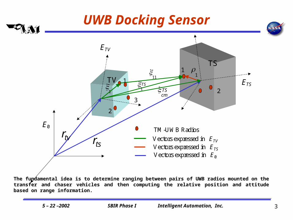
UWB Docking Sensor
0 E
TV E
TS E
TS
TV
ts r tv r
1
2
3
1
2 1 TS
11
1 TS cm
1
Vectors expressed in TV E Vectors expressed in TS E
0 Vectors expressed in E
TM-UWB Radios
The fundamental idea is to determine ranging between pairs of UWB radios mounted on the transfer and chaser vehicles and then computing the relative position and attitude based on range information.

5 – 22 –2002 SBIR Phase I Intelligent Automation, Inc.
4
UWB Technology Overview
• Time Domain Corporation (Time Domain) has developed a wireless radio frequency (RF) technology (PulsOn ®), which enables new capabilities in communications, precision positioning and radar sensing.
• PulsON architectures are characterized by:
– Ultra-short duration pulses, which yield ultra wideband width signals.
– Extremely low power spectral densities.
– Excellent immunity to interference from other radio systems.
5 – 22 –2002 SBIR Phase I Intelligent Automation, Inc.
5
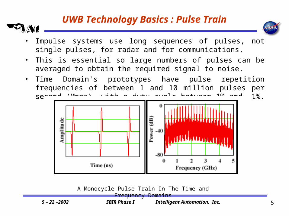
UWB Technology Basics : Pulse Train
• Impulse systems use long sequences of pulses, not single pulses, for radar and for communications.
• This is essential so large numbers of pulses can be averaged to obtain the required signal to noise.
• Time Domain's prototypes have pulse repetition frequencies of between 1 and 10 million pulses per second (Mpps), with a duty cycle between 1% and .1%.
A Monocycle Pulse Train In The Time and Frequency Domains
5 – 22 –2002 SBIR Phase I Intelligent Automation, Inc.
6
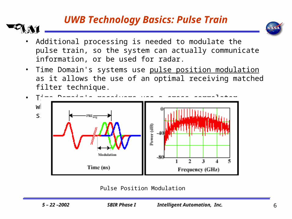
UWB Technology Basics: Pulse Train
• Additional processing is needed to modulate the pulse train, so the system can actually communicate information, or be used for radar.
• Time Domain's systems use pulse position modulation as it allows the use of an optimal receiving matched filter technique.
• Time Domain's receivers use a cross correlator, which gives the receiver the ability to find the signal well below the ambient noise level.
Pulse Position Modulation

5 – 22 –2002 SBIR Phase I Intelligent Automation, Inc.
7
UWB Technology Basics: Psuedo Random Coding
• By shifting each pulse's actual transmission time over a large time frame in accordance with a code one can channelize a pulse train.
• Time Domain uses "pseudo-random noise" codes (PRN codes) for this purpose.
• For a multiple access, each user would have their own pseudo-random noise code sequence.
• Only a receiver operating with the same pseudo-random noise code sequence can decode the transmission.
Pseudo-random Noise Coding
In Freq. Domain PRN Code appears
as noise

5 – 22 –2002 SBIR Phase I Intelligent Automation, Inc.
8
Experimental Setup
Example of one receiving antenna locking to each antenna from the mobile platform in a sequential manner
Reference platform
5 – 22 –2002 SBIR Phase I Intelligent Automation, Inc.
9
Summary of Phase I Results
• Radios do not noticeably interfere with one another, even when spaced within a few feet from each other, providing several configurations for optimally mounting the hardware.
• Weight per radio is less than 12oz for current hardware, new hardware available for Phase II will weigh considerably less.
• The radios can be used simultaneously for ranging and data transmission.

5 – 22 –2002 SBIR Phase I Intelligent Automation, Inc.
10
Detailed Presentation
5 – 22 –2002 SBIR Phase I Intelligent Automation, Inc.
11
Phase I Objectives
• Demonstrate the feasibility of developing a docking using UWB-based sensor technology
• Specific Objectives– Over all design of the UWB docking sensor
– Determine sensor limits on timing of acquisition and initialization
– Expected ranging limits and accuracies
– Physical layout of the hardware : tradeoff w.r.t proximity, accuracy and interference
5 – 22 –2002 SBIR Phase I Intelligent Automation, Inc.
12
UWB Technology Overview
• Time Domain Corporation (Time Domain) has developed a wireless radio frequency (RF) technology (PulsOn ®), which enables new capabilities in communications, precision positioning and radar sensing.
• PulsON architectures are characterized by:
– Ultra-short duration pulses, which yield ultra wideband width signals.
– Extremely low power spectral densities.
– Excellent immunity to interference from other radio systems.

5 – 22 –2002 SBIR Phase I Intelligent Automation, Inc.
13
UWB Technology Basics : Pulse Train
• Impulse systems use long sequences of pulses, not single pulses, for radar and for communications.
• This is essential so large numbers of pulses can be averaged to obtain the required signal to noise.
• Time Domain's prototypes have pulse repetition frequencies of between 1 and 10 million pulses per second (Mpps), with a duty cycle between 1% and .1%.
A Monocycle Pulse Train In The Time and Frequency Domains

5 – 22 –2002 SBIR Phase I Intelligent Automation, Inc.
14
UWB Technology Basics: Pulse Train
• Additional processing is needed to modulate the pulse train, so the system can actually communicate information, or be used for radar.
• Time Domain's systems use pulse position modulation as it allows the use of an optimal receiving matched filter technique.
• Time Domain's receivers use a cross correlator, which gives the receiver the ability to find the signal well below the ambient noise level.
Pulse Position Modulation
5 – 22 –2002 SBIR Phase I Intelligent Automation, Inc.
15
UWB Technology Basics: Psuedo Random Coding
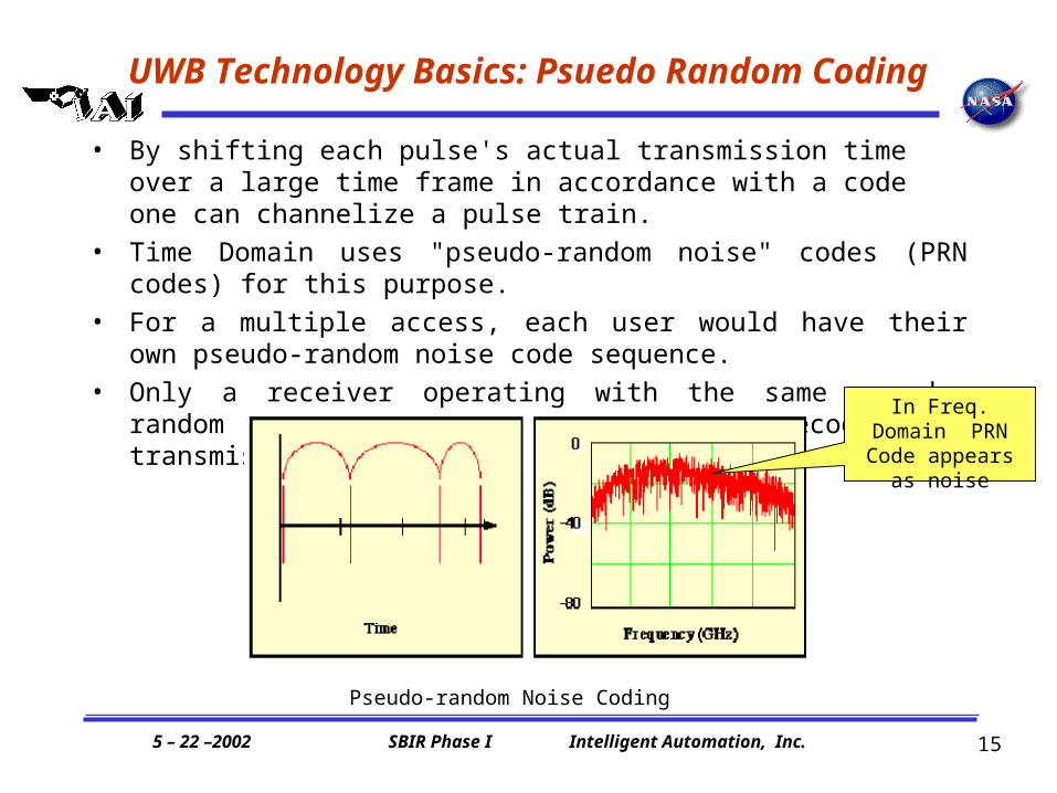
• By shifting each pulse's actual transmission time over a large time frame in accordance with a code one can channelize a pulse train.
• Time Domain uses "pseudo-random noise" codes (PRN codes) for this purpose.
• For a multiple access, each user would have their own pseudo-random noise code sequence.
• Only a receiver operating with the same pseudo-random noise code sequence can decode the transmission.
Pseudo-random Noise Coding
In Freq. Domain PRN Code appears
as noise
5 – 22 –2002 SBIR Phase I Intelligent Automation, Inc.
16
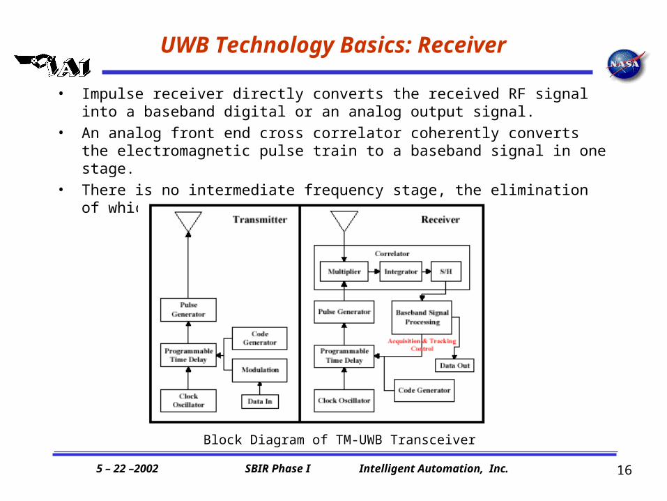
UWB Technology Basics: Receiver
• Impulse receiver directly converts the received RF signal into a baseband digital or an analog output signal.
• An analog front end cross correlator coherently converts the electromagnetic pulse train to a baseband signal in one stage.
• There is no intermediate frequency stage, the elimination of which reduces complexity.
Block Diagram of TM-UWB Transceiver

5 – 22 –2002 SBIR Phase I Intelligent Automation, Inc.
17
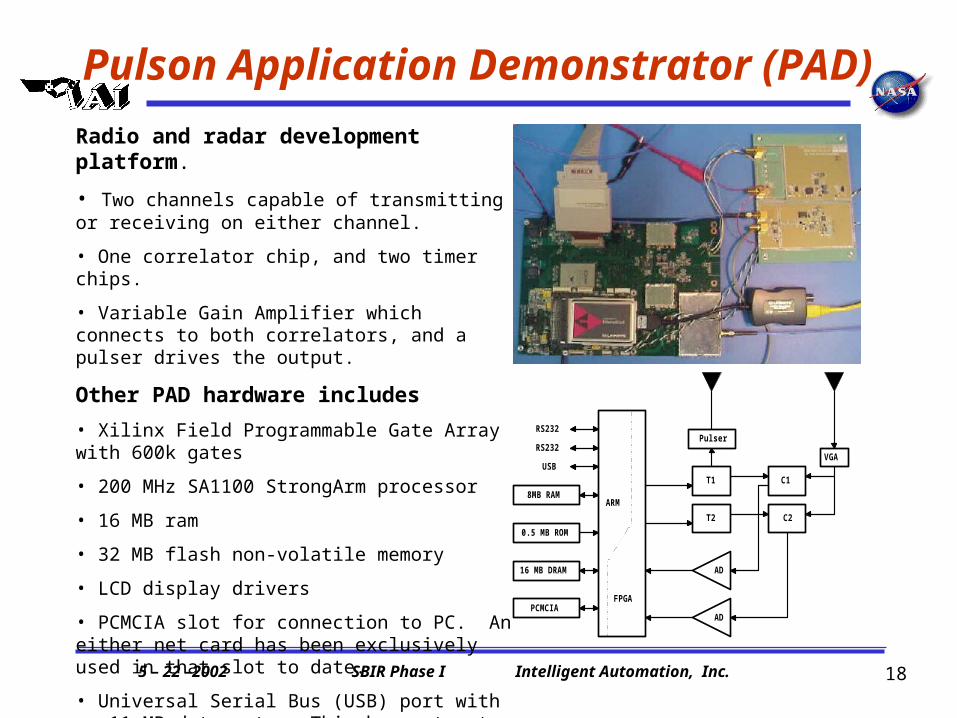
Pulson Application Demonstrator (PAD)
Pulson Application Demonstrator (PAD)Broadspec Antenna (Bandwidth >5GHz)
5 – 22 –2002 SBIR Phase I Intelligent Automation, Inc.
18
Pulson Application Demonstrator (PAD)
ARM
FPGA
AD
AD
Pulser
T1
T2
C1
C2
8MB RAM
0.5 MB ROM
16 MB DRAM
PCMCIA
RS232
RS232
USBVGA
Radio and radar development platform.
• Two channels capable of transmitting or receiving on either channel.
• One correlator chip, and two timer chips.
• Variable Gain Amplifier which connects to both correlators, and a pulser drives the output.
Other PAD hardware includes
• Xilinx Field Programmable Gate Array with 600k gates
• 200 MHz SA1100 StrongArm processor
• 16 MB ram
• 32 MB flash non-volatile memory
• LCD display drivers
• PCMCIA slot for connection to PC. An either net card has been exclusively used in that slot to date.
• Universal Serial Bus (USB) port with an 11 MB data rate. This has not yet been used.
• 512KB boot ROM for booting processor

5 – 22 –2002 SBIR Phase I Intelligent Automation, Inc.
19
UWB Docking Sensor
0 E
TV E
TS E
TS
TV
ts r tv r
1
2
3
1
2 1 TS
11
1 TS cm
1
Vectors expressed in TV E Vectors expressed in TS E
0 Vectors expressed in E
TM-UWB Radios
The fundamental idea is to determine ranging between pairs of UWB radios mounted on the transfer and chaser vehicles and then computing the relative position and attitude based on range information.
5 – 22 –2002 SBIR Phase I Intelligent Automation, Inc.
20
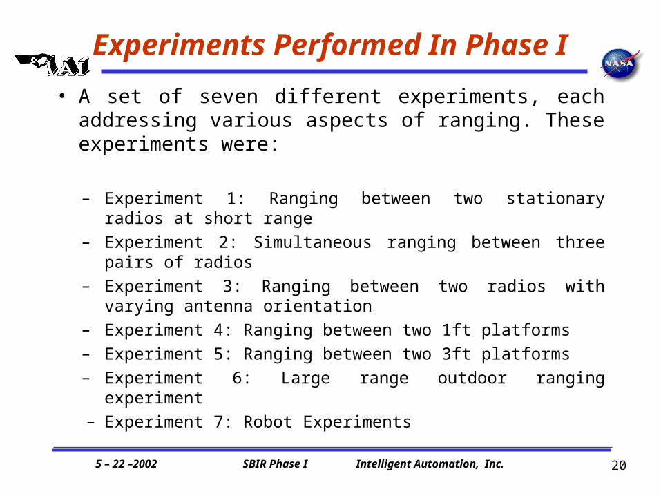
Experiments Performed In Phase I
• A set of seven different experiments, each addressing various aspects of ranging. These experiments were:
– Experiment 1: Ranging between two stationary radios at short
range
– Experiment 2: Simultaneous ranging between three pairs of radios
– Experiment 3: Ranging between two radios with varying antenna orientation
– Experiment 4: Ranging between two 1ft platforms
– Experiment 5: Ranging between two 3ft platforms
– Experiment 6: Large range outdoor ranging experiment
– Experiment 7: Robot Experiments

5 – 22 –2002 SBIR Phase I Intelligent Automation, Inc.
21
Ranging Between Antenna Pairs
• Experiments were performed with two 1ft and 3ft plates with 3 and 4 antennas
• Each antenna has dedicated radio• Ranging is sequential
Procedure:
• Find 3D coordinates of reference antennas (R1-R4)
and mobile antennas (M1-M3) with respect to plates
• Level each plate, measure distance from floor
• Mark location of each support• Transform antenna coordinates to
lab-frame of reference• Compute expected ranges• Take range data• Compute errors in ranges

5 – 22 –2002 SBIR Phase I Intelligent Automation, Inc.
22
Experimental Setup
Example of one receiving antenna locking to each antenna from the mobile platform in a sequential manner
Reference platform
5 – 22 –2002 SBIR Phase I Intelligent Automation, Inc.
23
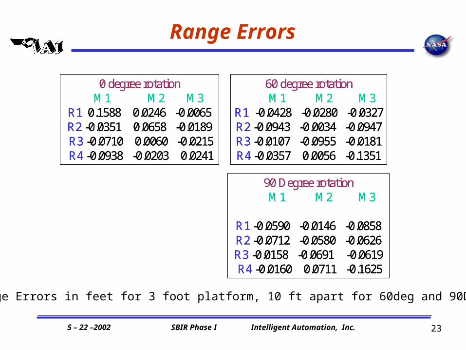
Range Errors
60 degree rotationM1 M2 M3
R1 -0.0428 -0.0280 -0.0327R2 -0.0943 -0.0034 -0.0947R3 -0.0107 -0.0955 -0.0181R4 -0.0357 0.0056 -0.1351
90 Degree rotationM1 M2 M3
R1 -0.0590 -0.0146 -0.0858R2 -0.0712 -0.0580 -0.0626R3 -0.0158 -0.0691 -0.0619R4 -0.0160 0.0711 -0.1625
0 degree rotationM1 M2 M3
R1 0.1588 0.0246 -0.0065R2 -0.0351 0.0658 -0.0189R3 -0.0710 0.0060 -0.0215R4 -0.0938 -0.0203 0.0241
Range Errors in feet for 3 foot platform, 10 ft apart for 60deg and 90Deg Yaw

5 – 22 –2002 SBIR Phase I Intelligent Automation, Inc.
24
Ranging and Audio Communication*
Shows 3-D tracking and video and audio communication happening simultaneously. IAI engineer Ben Lonske is wearing both the headsets (the one hooked-up to the mobile radio laptop and one to the reference radios’ desktop computer) to be able to monitor the audio quality of both channels
Four reference radios ranged to a mobile radio to perform 3D tracking while simultaneously doing a NetMeeting video conference.
*These measurements were performed under NASA Phase II project Time-Modulated Ultra-Wideband Multichannel Data System

5 – 22 –2002 SBIR Phase I Intelligent Automation, Inc.
25
Summary of Phase I Results
• With current hardware, range measurements were taken at a 300ms data rate at ranges between about 2m and 250m (though signal strength was recorded out to 572m)
• Standard deviation of the data is of the order of 0.01-0.02m. Accuracy is of similar magnitude, is limited by multipath interference, and can be improved by time averaging. For a 1m platform this yields about 1 degree accuracy in angular measurements. The accuracy for space application where multipath interference is limited, will be significantly more.
• Currently, ranging can be performed at a 1/300ms rate. The rate is presently limited by the acquisition process, which will be performed entirely in hardware (in one clock cycle) in the new hardware. After discussions with TDC, we believe that sampling rates will be improved to at least a few hundred Hz, possibly 1KHz or higher.
5 – 22 –2002 SBIR Phase I Intelligent Automation, Inc.
26
Summary of Phase I Results
• Noise on the range measurements appears normally distributed, and de-correlated within one sampling time. This suggests that accuracy can be improved significantly by time-averaging
• Ranging performance is completely insensitive to antenna yaw, allowing for
effective ranging and operation of a TM-UWB navigation system for all yaw angles between –180 and 180 degrees.
• Some sensitivity to antenna pitch, and roll is seen (std doubles for 30 degree pitch). It appears that this sensitivity is due to multipath(ground) interference, which would not be an issue for docking applications.
• Total power requirements of complete PADS (including Ethernet, fan, FPGA, serial port, and other elements) is about 7W. At most four units would be needed on the chaser vehicle, three would be needed on the target vehicle. Alternatively, one radio could be used on each vehicles, and multiple antennas address sequentially, at some cost to the data rate.

5 – 22 –2002 SBIR Phase I Intelligent Automation, Inc.
27
Summary of Phase I Results
• Radios do not noticeably interfere with one another, even when spaced within a few feet from each other, providing several configurations for optimally mounting the hardware.
• Weight per radio is less than 12oz for current hardware, new hardware available for Phase II will weigh considerably less.
• The radios can be used simultaneously for ranging and data transmission.
5 – 22 –2002 SBIR Phase I Intelligent Automation, Inc.
28
Phase II Objectives
• Thoroughly characterize ranging performance of next generation hardware under both static and dynamic conditions
• Determine how range errors propagate to uncertainty in the estimation of the six degrees of freedom of the target vehicle.
• Determine the optimum hardware configuration
• Customize hardware elements (power/range/packaging), and ranging software/firmware for the docking sensor
• Evaluate and ameliorate radiation vulnerability of key components
• Integrate UWB relative tracking with Global Positioning System (GPS)
• Incorporate the ranging system in a trajectory planner or motion controller
• Design, fabricate and deliver prototype UWB-Docking Sensor to JSC