4–stroke air-cooled v-twin gasoline engine service manual
TRANSCRIPT

FH601D, FH641DFH680D
4–stroke air-cooled v-twin gasoline engine
Service Manual
All rights reserved. No parts of this publication may be reproduced, stored in a retrieval system, or transmitted in anyform or by any means, electronic mechanical photocopying, recording or otherwise, without the prior written permission ofQuality Assurance Department/Consumer Products & Machinery Group/Kawasaki Heavy Industries, Ltd., Japan.
No liability can be accepted for any inaccuracies or omissions in this publication, although every possible care has beentaken to make it as complete and accurate as possible.
The right is reserved to make changes at any time without prior notice and without incurring an obligation to make suchchanges to products manufactured previously.
All information contained in this publication is based on the latest product information available at the time of publication.Illustrations and photographs in this publication are intended for reference use only and may not depict actual modelcomponent parts.
© Kawasaki Heavy Industries, Ltd. 2000 Second Edition (1) : Dec. 11, 2000 (K)
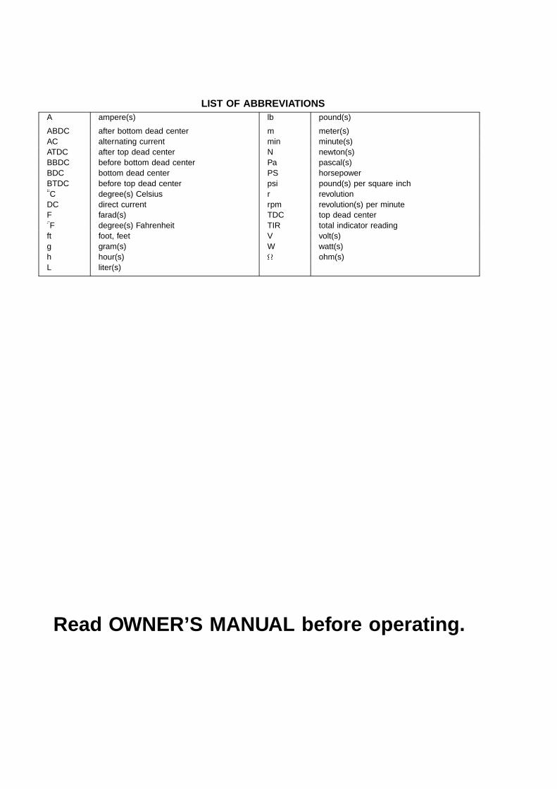
LIST OF ABBREVIATIONSA ampere(s) lb pound(s)
ABDC after bottom dead center m meter(s)AC alternating current min minute(s)ATDC after top dead center N newton(s)BBDC before bottom dead center Pa pascal(s)BDC bottom dead center PS horsepowerBTDC before top dead center psi pound(s) per square inch�C degree(s) Celsius r revolutionDC direct current rpm revolution(s) per minuteF farad(s) TDC top dead center�F degree(s) Fahrenheit TIR total indicator readingft foot, feet V volt(s)g gram(s) W watt(s)h hour(s) ohm(s)L liter(s)
Read OWNER’S MANUAL before operating.
EMISSION CONTROL INFORMATION
To protect the environment in which we all live, Kawasaki has incorporated crankcase emission (1) and exhaust emission(2) control systems (EM) in compliance with applicable regulations of the United States Environmental Protection Agencyand California Air Resources Board.
1. Crankcase Emission Control SystemA sealed-type crankcase emission control system is used to eliminate blow-by gasses. The blow-by
gasses are led to a breather chamber through the crankcase and from there to the air cleaner.Oil is separated from the gasses while passing through the inside of the breather chamber from the
crankcase, and then returned to the bottom of crankcase.2. Exhaust Emission Control System
The exhaust emission control system applied to this engine consists of a carburetor and an ignitionsystem having optimum ignition timing characteristics.
The carburetor has been calibrated to provide lean air/fuel mixture characteristics and optimum fueleconomy with a suitable air cleaner and exhaust system.
TAMPERING WITH EMISSION CONTROL SYSTEM PROHIBITED
Federal law and California State law prohibits the following acts or the causing thereof: (1) the removal or renderinginoperative by any person other than for purposes of maintenance, repair, or replacement, of any device or element ofdesign incorporated into any new engine for the purpose of emission control prior to its sale or delivery to the ultimatepurchaser or while it is in use, or (2) the use of the engine after such device or element of design has been removed orrendered inoperative by any person.
Among those acts presumed to constitute tampering are the acts listed below:Do not tamper with the original emission related part:
• Carburetor and internal parts• Spark plugs• Magneto or electronic ignition system• Fuel filter element• Air cleaner elements• Crankcase• Cylinder heads• Breather chamber and internal parts• Intake pipe and tube
Foreword
This manual is designed primarily for use by trainedmechanics in a properly equipped shop. However, itcontains enough detail and basic information to makeit useful to the owner who desires to perform his ownbasic maintenance and repair work. A basic knowledgeof mechanics, the proper use of tools, and workshopprocedures must be understood in order to carry outmaintenance and repair satisfactorily. Whenever theowner has insufficient experience or doubts as to hisability to do the work, all adjustments, maintenance, andrepair should be carried out only by qualified mechanics.
In order to perform the work efficiently and to avoidcostly mistakes, read the text, thoroughly familiarizeyourself with the procedures before starting work, andthen do the work carefully in a clean area. Wheneverspecial tools or equipment are specified, do not usemakeshift tools or equipment. Precision measurementscan only be made if the proper instruments are used,and the use of substitute tools may adversely affect safeoperation.
To get the longest life out of your engine:
• Follow the Periodic Maintenance Chart in the ServiceManual.
• Be alert for problems and non-scheduled maintenance.
• Use proper tools and genuine Kawasaki engine parts.Genuine parts provided as spare parts are listed in theParts Catalog.
• Follow the procedures in this manual carefully. Don’ttake shortcuts.
• Remember to keep complete records of maintenanceand repair with dates and any new parts installed.
How to Use This ManualIn preparing this manual, we divided the product into
its major systems. These systems became the manual’schapters. All information for a particular system fromadjustment through disassembly and inspection is locatedin a single chapter.
The Quick Reference Guide shows you all of theproduct’s system and assists in locating their chapters.Each chapter in turn has its own comprehensive Table ofContents.
The Periodic Maintenance Chart is located in theGeneral Information chapter. The chart gives a timeschedule for required maintenance operations.
If you want spark plug information, for example, go tothe Periodic Maintenance Chart first. The chart tells youhow frequently to clean and gap the plug. Next, use theQuick Reference Guide to locate the Electrical Systemchapter. Then, use the Table of Contents on the first pageof the chapter to find the Spark Plug section.
Whenever you see these WARNING and CAUTIONsymbols, heed their instructions! Always follow safeoperating and maintenance practices.
This warning symbol identifies special instruc-tions or procedures which, if not correctly fol-lowed, could result in personal injury, or loss oflife.
CAUTION
This caution symbol identifies special instruc-tions or procedures which, if not strictly ob-served, could result in damage to or destructionof equipment.
This manual contains four more symbols (in addition toWARNING and CAUTION) which will help you distinguishdifferent types of information.
NOTE
This note symbol indicates points of particular in-terest for more efficient and convenient operation.
• Indicates a procedural step or work to be done. Indicates a procedural sub-step or how to do the work
of the procedural step it follows. It also precedes thetext of a WARNING, CAUTION, or NOTE.Indicates a conditional step or what action to take basedon the results of the test or inspection in the proceduralstep or sub-step it follows.
In most chapters an exploded view illustration of thesystem components follows the Table of Contents. Inthese illustrations you will find the instructions indicatingwhich parts require specified tightening torque, oil, greaseor a locking agent during assembly.

GENERAL INFORMATION 1-1
General Information
Table of Contents
1
Before Servicing.................................................................................................................................................................1-2Model Identification ............................................................................................................................................................ 1-4General Specifications ....................................................................................................................................................... 1-5Periodic Maintenance Chart...............................................................................................................................................1-6Torque and Locking Agent .................................................................................................................................................1-7Special Tools ......................................................................................................................................................................1-9

1-2 GENERAL INFORMATIONBefore Servicing
Before starting to service the engine, carefully read the applicable section to eliminate unnecessary work. Photographs,diagrams, notes, cautions, warnings, and detailed descriptions have been included wherever necessary. Nevertheless,even a detailed account has limitations, a certain amount of basic knowledge is required for successful work.
Especially note the following:(1) Dirt
Before removal and disassembly, clean the engine. Any dirt entering the engine, carburetor, or other parts, willwork as an abrasive and shorten the life of engine. For the same reason, before installing a new part, clean off anydust or metal filings.
(2) Battery GroundRemove the ground (—) lead from the battery before performing any disassembly operations on the equipment.
This prevents:(a) the possibility of accidentally turning the engine over while partially disassembled.(b) sparks at electrical connections which will occur when they are disconnected.(c) damage to electrical parts.
(3) Tightening SequenceGenerally, when installing a part with several bolts, nuts, or screws, start them all in their holes and tighten them to
a snug fit. Then tighten them evenly, in a staggered sequence. This is to avoid distortion of the part and/or causinggas or oil leakage. Conversely when loosening the bolts, nuts, or screws, first loosen all of them by about a quarterof a turn and then remove them. Where there is a tightening sequence indication in this Service Manual, the bolts,nuts, or screws must be tightened in the order and method indicated.
(4) TorqueWhen torque values are given in this Service Manual, use them. Either too little or too much torque may lead to
serious damage. Use a good quality, reliable torque wrench.(5) Force
Common sense should dictate how much force is necessary in assembly and disassembly. If a part seems especiallydifficult to remove or install, stop and examine what may be causing the problem. Whenever tapping is necessary, taplightly using a wooden or plastic-faced mallet. Use an impact driver for screws (particularly for the removal of screwsheld by a locking agent) in order to avoid damaging the heads.
(6) EdgesWatch for sharp edges, especially during major engine disassembly and assembly. Protect your hands with gloves
or a piece of thick cloth when lifting the engine or turning it over.(7) High-Flash Point Solvent
A high-flash point solvent is recommended to reduce fire danger. A commercial solvent commonly available in NorthAmerica is Standard solvent (generic name). Always follow manufacturer and container directions regarding the useof any solvent.
(8) Gasket, O-RingDo not reuse a gasket or O-ring once it has been in service. The mating surfaces around the gasket should be
free of foreign matter and perfectly smooth to avoid oil or compression leaks.(9) Liquid Gasket, Non-Permanent Locking Agent
Follow manufacturer’s directions for cleaning and preparing surfaces where these compounds will be used. Applysparingly. Excessive amounts may block engine oil passages and cause serious damage. An example of a non-permanent locking agent commonly available in North America is Loctite Lock’n Seal (Blue).
(10) PressA part installed using a press or driver, such as a journal, should first be coated with oil on its outer or inner
circumference so that it will go into place smoothly.(11) Ball Bearing
When installing a ball bearing, the bearing race which is affected by friction should be pushed by a suitable driver.This prevents severe stress on the balls and races, and prevents races and balls from being dented. Press a ballbearing until it stops at the stop in the hole or on the shaft.
(12) Oil Seal and Grease SealReplace any oil or grease seals that were removed with new ones, as removal generally damages seals.When pressing in a seal which has manufacturer’s marks, press it in with the marks facing out. Seals should be
pressed into place using a suitable driver, which contacts evenly with the side of seal, until the face of the seal is evenwith the end of the hole.
(13) Seal GuideA seal guide is required for certain oil or grease seals during installation to avoid damage to the seal lips. Before
a shaft passes through a seal, apply a little oil, preferably high temperature grease on the lips to reduce rubber tometal friction.
(14) Circlip, Retaining RingReplace any circlips and retaining rings that were removed with new ones, as removal weakens and deforms them.
When installing circlips and retaining rings, take care to compress or expand them only enough to install them andno more.
GENERAL INFORMATION 1-3Before Servicing
(15) Cotter PinReplace any cotter pins that were removed with new ones, as removal deforms and breaks them.
(16) LubricationEngine wear is generally at its maximum while the engine is warming up and before all the rubbing surfaces have
an adequate lubricative film. During assembly, oil or grease (whichever is more suitable) should be applied to anyrubbing surface which has lost its lubricative film. Old grease and dirty oil should be cleaned off. Deteriorated greasehas lost its lubricative quality and may contain abrasive foreign particles.
Don’t use just any oil or grease. Some oils and greases in particular should be used only in certain applications andmay be harmful if used in an application for which they are not intended. This manual makes reference to molybdenumdisulfide grease (MoS2) in the assembly of certain engine parts. Always check manufacturer recommendations beforeusing such special lubricants.
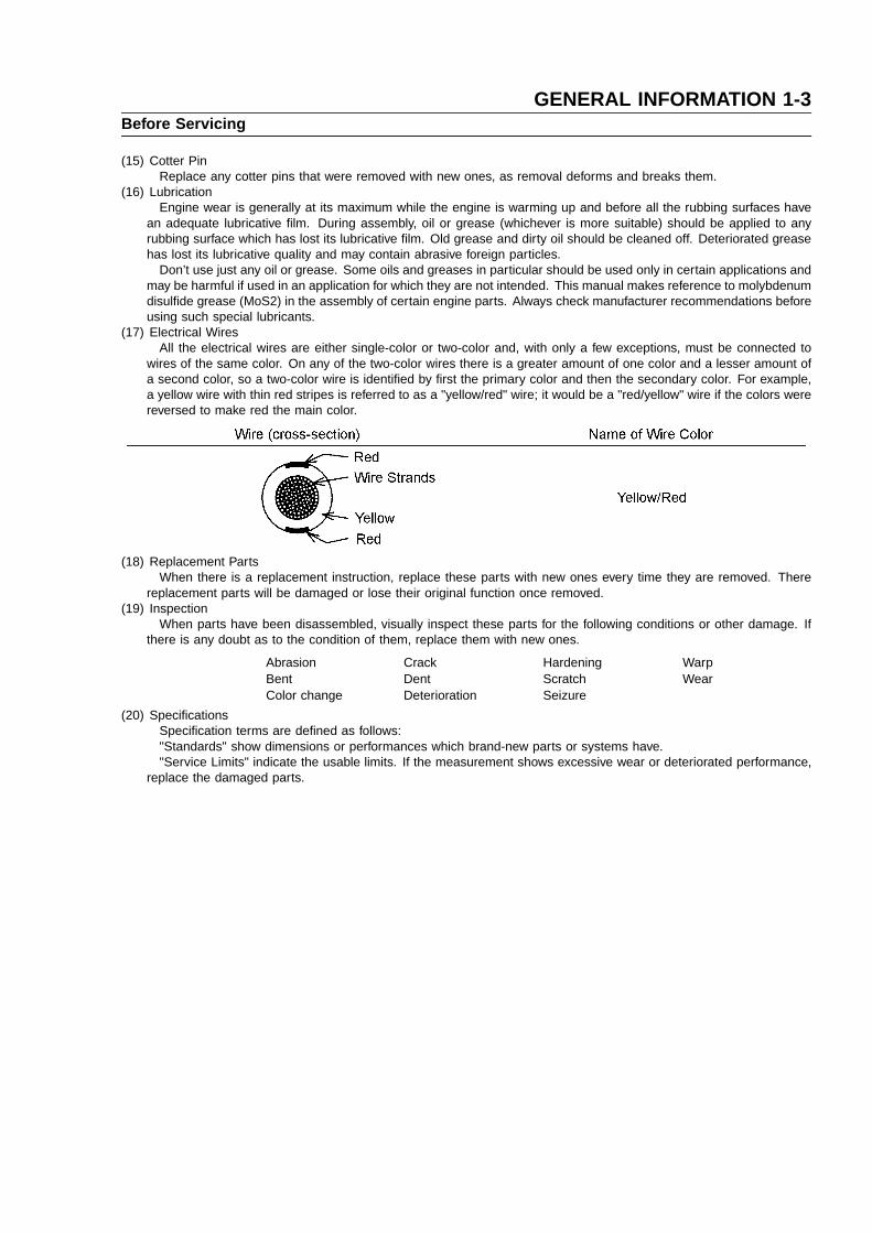
(17) Electrical WiresAll the electrical wires are either single-color or two-color and, with only a few exceptions, must be connected to
wires of the same color. On any of the two-color wires there is a greater amount of one color and a lesser amount ofa second color, so a two-color wire is identified by first the primary color and then the secondary color. For example,a yellow wire with thin red stripes is referred to as a "yellow/red" wire; it would be a "red/yellow" wire if the colors werereversed to make red the main color.
(18) Replacement PartsWhen there is a replacement instruction, replace these parts with new ones every time they are removed. There
replacement parts will be damaged or lose their original function once removed.(19) Inspection
When parts have been disassembled, visually inspect these parts for the following conditions or other damage. Ifthere is any doubt as to the condition of them, replace them with new ones.
Abrasion Crack Hardening WarpBent Dent Scratch WearColor change Deterioration Seizure
(20) SpecificationsSpecification terms are defined as follows:"Standards" show dimensions or performances which brand-new parts or systems have."Service Limits" indicate the usable limits. If the measurement shows excessive wear or deteriorated performance,
replace the damaged parts.

1-4 GENERAL INFORMATIONModel Identification
Cylinder Number Designation:No.1 Cylinder is on the electric starter side.No.2 Cylinder is on the oil fileter side.

GENERAL INFORMATION 1-5General Specifications
Items FH601D, FH641D, FH680D
Type of engine Forced air-cooled, horizontal shaft, OHV, 4-stroke gasoline engine.
Cylinder layout 90� V-Twin
Bore x Stroke 75.2 mm x 76 mm (2.96 in x 2.99 in)
Piston displacement 675 mL (41.19 cu. in)
Direction of rotation Counterclockwise facing the PTO shaft
Compression release Automatic compression release
Low idle speed 1550 rpm
Fast idle speed 3600 rpm
Ignition system Transistorized-fly wheel magneto
RFI Per Canada and U.S.A. requirements
Starting system Electric starter
Charging system 12 V - 13 amps with regulator
Spark plug NGK BPR4ES
Carburetor Float type, fixed main jet, two barrel
Fuel pump Diaphragm type pulse pump
Air cleaner Dual stage element, dry type
Governor Flyweight all speed governor
Lubrication system Pressure feed by positive displacement pump
Oil filter Cartridge type full flow filter
Oil pressuer switch ON-OFF switch
Oil capacity 1.6 L (1.7 US�qt)…(when engine is completely dry)
Cooling system Forced air cooling by fan
Dimensions (L x W x H ): without muffler 442 mm x 430 mm x 491 mm (17.4 in x 16.9 in x 19.3 in)
Dry weight: without muffler 44.5 kg (98.1 lb)
Specifications are subject to change without notice.

1-6 GENERAL INFORMATIONPeriodic Maintenance Chart
To ensure satisfactory operation over an extended period of time, any engine requires normal maintenance regularintervals. The Periodic Maintenance Chart below shows periodic inspection and maintenance items and suitable intervals.The bullet mark (•) designates that the corresponding item should be performed at that interval.
Some adjustments require the use of special tools or other equipment. An electronic tachometer will facilitate settingidle and running speeds.
OPERATION INTERVAL
DailyFirst8 hr.
Every25 hr.
Every50 hr.
Every100 hr.
Every200 hr.
Every300 hr.
Check or clean air intake screen •Check and add engine oil •Check for fuel and oil leakage •Check for loose or lost nut and screw •Check battery electrolyte level •Clean air cleaner foam element (1) •Clean air cleaner paper element (1) •Clean dust and dirt from cylinder and •
cylinder head fins (1)
Tighten nut and screws •Change engine oil • •Clean and re-gap spark plugs •Change Oil filter •Change air cleaner paper element (1) •
♦ Check and adjust vlave clearance •♦ Clean and lap valve seating surface •♦ Clean combustion chamber •
(1): Service more frequently under dusty conditions.♦: These items must be performed with the proper tools. See your authorized Kawasaki Engine Dealer for service,
unless you have the proper equipment and mechanical proficiency.

GENERAL INFORMATION 1-7Torque and Locking Agent
The following tables lists the tightening torque for the major fasteners, and the parts requiring use of a non-permanentlocking agent or liquid gasket.
Letters used in the "Remarks" column mean:L : Apply a non-permanent locking agent to the threads.M : Apply a molybdenum disulfide lubricant (grease or oil) to the threads, seated surface, or washer.O : Apply an oil to the threads, seated surface, or washer.S : Tighten the fasteners following the specified sequence.
SS : Apply silicone sealant.
Fastener Torque Remarks
N�m kg �m ft �lb
Fuel System:
Choke Valve Screw ♦0.95 ♦0.097 ♦8.4 in �lb ♦=L
Throttle Valve Screws ♦0.95 ♦0.097 ♦8.4 in �lb ♦=L
Plug, Main Jet 18 1.8 13
Drain Screw (Carburetor) 2.0 0.2 18 in�lb
Fuel Shut Off Solenoid Valve (Carburetor) 19 1.9 14
Float Chamber Mounting Screw (Carburetor) 4.0 0.4 35 in�lb
Governor Arm Clamp Nut 7.8 0.8 69 in�lb
Governor Shaft Plate Screws 2.0 0.2 17 in�lb
Carburetor and Intake Pipe Mounting Bolts and Nuts 5.9 0.6 52 in�lb
Intake Manifold Mounting Bolts 5.9 0.6 52 in�lb
Air Cleaner Body Mounting Bolts 5.9 0.6 52 in�lb
Control Panel Mounting Bolts 5.9 0.6 52 in�lb
Cooling System:
Screen Bolts 5.9 0.6 52 in�lb
Engine-shroud Bolt (M8: on Cylinder Head) 6.9 0.7 61 in�lb
Engine-shroud Bolts (M6) 5.9 0.6 52 in�lb
Engine Top End:
Cylinder Head Bolts ♦28 ♦2.8 ♦21 ♦=S
Valve Clearance Lock Screws 6.9 0.7 61 in�lb
Connecting Rod Big End Cap Bolts ♦9.8 ♦1.0 ♦87 in �lb ♦=O
Rocker Arm Bolts 28 2.8 21
Rocker Cover Mounting Bolts 6.9 0.7 61 in�lb
Muffler Flange Nuts 15 1.5 11
Spark Plugs 22 2.2 16
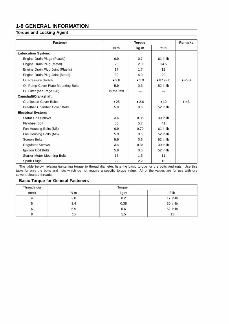
1-8 GENERAL INFORMATIONTorque and Locking Agent
Fastener Torque Remarks
N�m kg �m ft �lb
Lubrication System:
Engine Drain Plugs (Plastic) 6.9 0.7 61 in�lb
Engine Drain Plug (Metal) 20 2.0 14.5
Engine Drain Plug Joint (Plastic) 17 1.7 12
Engine Drain Plug Joint (Metal) 39 4.0 29
Oil Pressure Switch ♦9.8 ♦1.0 ♦87 in �lb ♦=SS
Oil Pump Cover Plate Mounting Bolts 5.9 0.6 52 in�lb
Oil Filter (see Page 5-6) in the text
Camshaft/Crankshaft:
Crankcase Cover Bolts ♦25 ♦2.6 ♦19 ♦=S
Breather Chamber Cover Bolts 5.9 0.6 52 in�lb
Electrical System:
Stator Coil Screws 3.4 0.35 30 in�lb
Flywheel Bolt 56 5.7 41
Fan Housing Bolts (M8) 6.9 0.70 61 in�lb
Fan Housing Bolts (M6) 5.9 0.6 52 in�lb
Screen Bolts 5.9 0.6 52 in�lb
Regulator Screws 3.4 0.35 30 in�lb
Ignition Coil Bolts 5.9 0.6 52 in�lb
Starter Motor Mounting Bolts 15 1.5 11
Spark Plugs 22 2.2 16
The table below, relating tightening torque to thread diameter, lists the basic torque for the bolts and nuts. Use thistable for only the bolts and nuts which do not require a specific torque value. All of the values are for use with drysolvent-cleaned threads.
Basic Torque for General Fasteners
Threads dia Torque
(mm) N�m kg�m ft�lb
4 2.0 0.2 17 in�lb
5 3.4 0.35 30 in�lb
6 5.9 0.6 52 in�lb
8 15 1.5 11

GENERAL INFORMATION 1-9Special Tools
Compression Gauge: 57001–221
Piston Ring Pliers: 57001–115
Piston Ring Compression Grip: 57001–1095
Piston Ring Compression Belt, Ø67 -Ø79: 57001–1097
Valve Seat Cutter Holder Bar: 57001–1128
Valve Seat Cutter Holder Ø6: 57001–1360
Valve Seat Cutter, 45 � – 35.0 : 57001–1116
Valve Seat Cutter, 30 � – 33.0 : 57001–1199
Compression Gauge Adapter M14 x 1.25: 57001–1159
Valve Seat Cutter, 30 � – 30 : 57001–1120

1-10 GENERAL INFORMATIONSpecial Tools
Oil Filter Wrench : 57001–1249
Hand Tester: 57001–1394
Kawasaki Bond (Silicone Sealant) : 56019–120

FUEL SYSTEM 2-1
Fuel System
Table of Contents
2
Exploded View.............................................................2-2Specifications...............................................................2-4Governor Link Mechanism.......................................... 2-5
Control Panel Assembly Removal........................2-5Control Panel Assembly Installation.....................2-5Governor Arm Removal........................................2-5Governor Arm Installation.....................................2-6Governor Assembly Removal...............................2-6Governor Assembly Installation............................2-6Governor Assembly Inspection.............................2-7Governor Shaft Removal......................................2-7Governor Shaft Installation...................................2-7
Carburetor....................................................................2-8Fuel and Air Flow.................................................2-8Fuel Shut Off Solenoid Valve (Electric StarterModel)...................................................................2-9Low Idle Speed Adjustment..................................2-9High Idle Speed Adjustment...............................2-10High Altitude Operation......................................2-11Main Jet Replacement........................................2-11Fuel System Cleanliness Inspection..................2-11
Carburetor Removal............................................2-11Carburetor Installation ........................................2-12Carburetor Disassembly/Assembly.....................2-13Carburetor Cleaning...........................................2-14Carburetor Inspection.........................................2-14Fuel Shut-Off Solenoid Valve Test ..................... 2-15
Intake Manifold..........................................................2-16Intake Manifold Removal ....................................2-16Intake Manifold Installation.................................2-16Intake Manifold Inspection..................................2-17
Fuel Pump, Fuel Filter...............................................2-18Fuel Pump Inspection.........................................2-18Fuel Filter Inspection..........................................2-18
Air Cleaner.................................................................2-19Element Removal ............................................... 2-19Element Installation............................................2-19Element Cleaning and Inspection.......................2-19Cleaner Body Removal.......................................2-20Cleaner Body Installation....................................2-20Housing (Cover and Body) Inspection ............... 2-20

2-2 FUEL SYSTEMExploded View
1. Pilot Screw2. Pilot Air Jet3. Main Air Jet4. Main Jet5. Pilot Jet6. Solenoid Valve
T1: 0.95 N�m (0.097 kg�m, 8.4 in�lb)T2: 0.98 N�m (0.1 kg�m, 8.7 in�lb)T3: 2.0 N�m (0.2 kg�m, 18 in�lb)T4: 3.4 N�m (0.35 kg�m, 30 in�lb)T5: 5.9 N�m (0.6 kg�m, 52 in�lb)T6: 19 N�m (1.9 kg�m, 14 ft�lb)

FUEL SYSTEM 2-3Exploded View
O: Apply engine oil.T1: 2.0 N�m (0.2 kg�m, 17 in�lb)T2: 5.9 N�m (0.6 kg�m, 52 in�lb)T3: 7.8 N�m (0.8 kg�m, 69 in�lb)
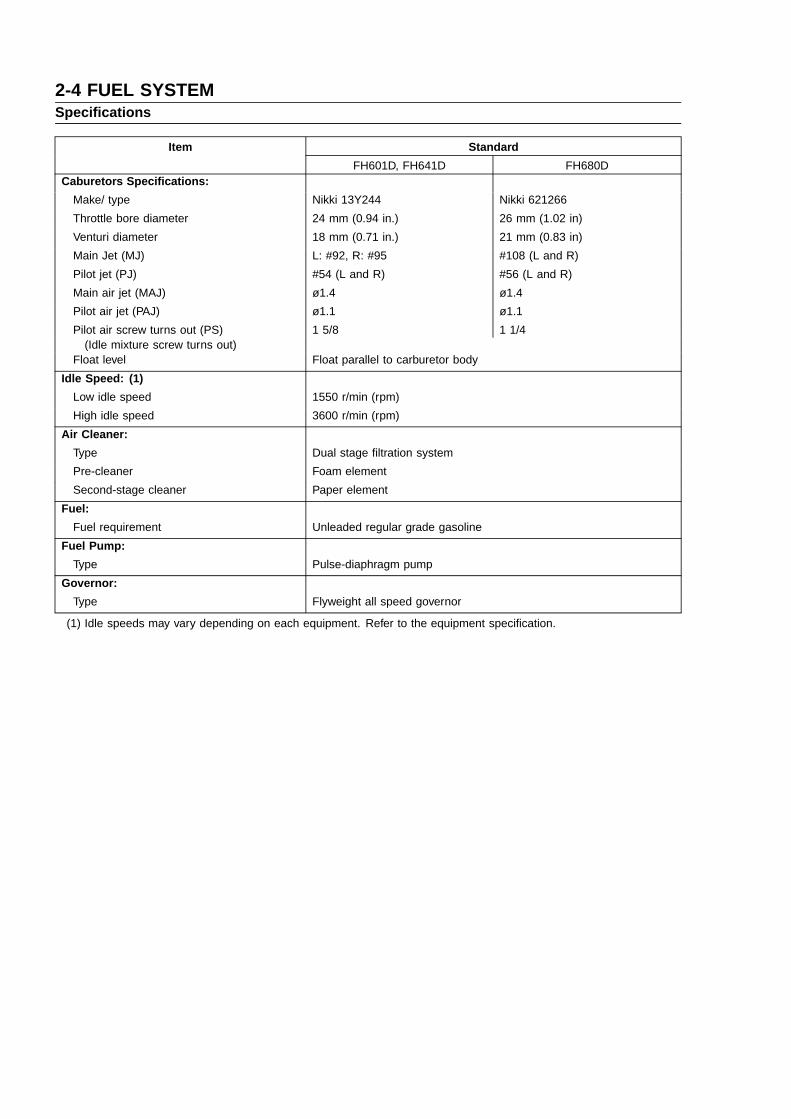
2-4 FUEL SYSTEMSpecifications
Item Standard
FH601D, FH641D FH680DCaburetors Specifications:
Make/ type Nikki 13Y244 Nikki 621266
Throttle bore diameter 24 mm (0.94 in.) 26 mm (1.02 in)
Venturi diameter 18 mm (0.71 in.) 21 mm (0.83 in)
Main Jet (MJ) L: #92, R: #95 #108 (L and R)
Pilot jet (PJ) #54 (L and R) #56 (L and R)
Main air jet (MAJ) ø1.4 ø1.4
Pilot air jet (PAJ) ø1.1 ø1.1
Pilot air screw turns out (PS) 1 5/8 1 1/4(Idle mixture screw turns out)
Float level Float parallel to carburetor body
Idle Speed: (1)
Low idle speed 1550 r/min (rpm)
High idle speed 3600 r/min (rpm)
Air Cleaner:
Type Dual stage filtration system
Pre-cleaner Foam element
Second-stage cleaner Paper element
Fuel:
Fuel requirement Unleaded regular grade gasoline
Fuel Pump:
Type Pulse-diaphragm pump
Governor:
Type Flyweight all speed governor
(1) Idle speeds may vary depending on each equipment. Refer to the equipment specification.

FUEL SYSTEM 2-5Governor Link Mechanism
Control Panel Assembly Removal
• Remove:Air Cleaner (see Cleaner Body Removal)Air Cleaner Mount Bracket Bolts [A]Air Cleaner Mount Bracket [B]Control Panel Mounting Bolts [C]
• Remove the control panel assembly [A] while unhooking the governorspring [B] end loop at the panel bracket.
• Clear the choke link rod end from the choke lever [C].
Control Panel Assembly Installation
• Before installing the control panel assembly, check to see that thechoke lever [A] and engine speed control lever [B] move smoothly inall directions.If any part is worn or damaged, replace the control panel assembly.
• After installation, adjust the low idle speeds and high idle speedsto the specifications (see Low Idle Speed and High Idle Speedadjustment).
Governor Arm Removal
• Remove:Control Panel Assembly
• Loosen the clamp nut [A] and take off the governor arm [B].
• Unhooking the throttle link rod spring [C] end loop and clear thethrottle link rod end [D].

2-6 FUEL SYSTEMGovernor Link Mechanism
Governor Arm Installation
• Insert the jig pin (2 mm dia) [I] through the jig pin hole of governorshaft [B].
• Install the governor arm [A] onto the governor shaft [B] temporarily.
• Be sure the link spring [C] around the throttle link rod [D] is inplaceand that it pulls the governor arm and throttle lever [E] each other.
• Loosen the clamp nut [F] on the governor arm enough to move thegovernor shaft.
• Turn the top end of the governor arm counterclockwise to fully openthe carburetor [G] throttle valve and hold it there.
• Using the jig pin [I], turn the governor shaft counterclockwise, fullyturn the shaft to end of its travel.
• Tighten the clamp nut.
Torque - Governor Arm Clamp Nut: 7.8 N �m (0.80 kg �m, 69 in �lb)
• Be sure the governor shaft extend from the governor arm is approxi-mately 6.5 mm (0.26 in) [H] as shown.
• Remove the jig pin [I].
• Install the control panel assembly, and connect the governor arm withthe governor spring.
Governor Assembly Removal
• Remove the crankcase cover (see Camshaft/Crankshaft chapter).
• Remove the push rod. (see Engine Top End chapter)
• Upside down the engine.
• Remove the camshaft [A].
• Remove:Washer [A]Snap Ring [B]Sleeve [C]Governor Plate [D]Snap Ring [B]Steel balls [E]Ball Guide [F]Ball Plate [G]
Governor Assembly Installation
• Fit the snap rings [A] into the grooves securely.
• Spin the governor plate by hand and check that the steel balls andgovernor plate operate freely.

FUEL SYSTEM 2-7Governor Link Mechanism
Governor Assembly Inspection Visually check all governor parts for wear and damage.
If any parts are worm or damaged, replace them.
Governor Shaft Removal
• Split the crankcase (see Camshaft/Crankcase chapter).
• Unscrew the governor shaft plate screws [A], and pull out the governorshaft [B] outside.
NOTE It is not necessary to remove the governor shaft unless it is being
replaced.
• Replace the oil seal only if the lip shows signs of leakage or it hasbeen damaged.
• When replacing the oil seal [A] of the governor shaft, note thefollowing.
Install the oil seal into the crankcase cover [B] after the governor shaftis inserted in the cover, and so that the marks [C] face out.
The depth [D] is 0 2 mm (0 0.08 in.).
Governor Shaft Installation
• Apply engine oil to the governor shaft.
• Insert the governor shaft into the crankcase.
• Install the governor shaft plate [A] to the shaft [B] as shown.
Torque - Governor Shaft Plate Screws: 2.0 N �m (0.20 kg �m, 17 in �lb)
• Check that the governor shaft moves freely in its operating range.
NOTE If the oil seal is removed, oil seal is put on after shaft is installed.

2-8 FUEL SYSTEMCarburetor
Fuel and Air FlowThe main system of the carburetor consists of the main jet [A], Valve
seat [B] main nozzle [C], and the main air passage [D] (main air jet[E]). The main system meters fuel to the engine during moderate toheavy load conditions. Fuel flows through the main jet and into themain nozzle, where it is joined by air from the main air passage (mainair jet). The resulting mixture flows out the end of the main nozzle intothe carburetor bore, where it is atomized by the high speed air flow, andcarried into the engine.
The pilot system includes the pilot jet [F], pilot air screw [G] (Idlemixture screw), pilot air jet [H], pilot outlet [I], and the bypass holes [J].The pilot system meters the fuel/air mixture while the engine is idlingand running under a light load. Under these conditions there is verylittle air flow through the carburetor bore; so little that it is not enoughto draw fuel through the main system of the carburetor and atomizeit. Instead, the fuel is drawn through the pilot system, since the nearlyclosed throttle valve [K] causes high speed air flow past the pilot outletand bypass holes (even at low engine speed).
Fuel flow in the pilot system is metered by the pilot jet. Air for betteratomization is admitted via the pilot air jet in the mouth of the carburetor.The fuel/air mixture passes into the bore of the carburetor side streamof the throttle valve through the bypass holes and pilot outlet. Whilethe throttle valve is almost closed, it covers the small bypass holesopening into the bore from the pilot system. As the throttle valve beginsto open, it uncovers the bypass holes, allowing more fuel/air mixture toflow. The extra flow is needed because the engine starts to run fasteras the throttle is opened. The pilot screw controls the amount of fuel/airmixture allowed through the pilot outlet, but does not meter the bypassholes. A moderate amount of air comes in around the throttle valve atan idle, so adjusting the pilot screw changes the fuel/air ratio. Turningthe pilot screw (Idle mixture screw) out (Counterclockwise) enrichensthe mixture; turning it in (clockwise) leans the mixture.
Main Fuel Flow !Pilot Fuel Flow ⇒

FUEL SYSTEM 2-9Carburetor
Fuel Shut Off Solenoid Valve (Electric Starter Model)To avoid after firing when stopping the engine, a solenoid actuated
fuel shut off solenoid valve [A] is installed in the carburetor bowl. Thevalve shuts off the fuel supply to the valve seat [B] simultaneously whenthe switch key turned to the “OFF” position.
The valve opens automatically when the switch key is turned to the“Run” position.
Low Idle Speed Adjustment
• Disconnect all possible external loads from the engine.
• Start the engine and warm it up thoroughly.
Always keep your hands clear of the moving parts.
• Move the throttle lever on dash to the idle position, and hold thethrottle lever on the carburetor in closed position (turn the governerarm clockwise all the way) and adjust the low idle speed screw [A]until the engine idles at specified speed.
Idle Speed (Carburetor idle rpm)1450 rpm
• Release the throttle lever and adjust the low idle speed set screw [B]on the control plate to obtain the specified governed low idle speed.
Low Idle Speed (Governed idle rpm)1550 rpm

2-10 FUEL SYSTEMCarburetor
High Idle Speed Adjustment
NOTE High idle speed adjustment should be made after the idle speed
adjustment is performed.
CAUTION
Do not adjust high idle speed with the air cleaner removed.
• Start and warm up the engine thoroughly.
Always keep your hands clear of the moving parts.
• Move the throttle lever at a dash to the high idle position and matchthe lever hole position with the panel hole by inserting 6 mm dia., pinor bolt [A].
• Loosen two M6 control panel mounting bolts [B] enough to move thecontrol panel assembly.
• Carefully move the control panel assembly right side [C] up or downto obtain the specified high idle speed.
High Idle Speed3600 rpm
• Tighten the M6 mounting bolts.
Torque - Control Panel Mounting Bolts: 5.9 N �m (0.60 kg �m, 52 in �lb)
• Remove the 6 mm dia., pin or bolt.
• Check the idle speed, and readjust the idle speed if necessary.
CAUTION
Be sure to make the idle and high idle speeds respectivelycorrespond to those of the equipment.
FUEL SYSTEM 2-11Carburetor
High Altitude OperationAt high altitude, the standard carburetor air-fuel mixture will be
excessively rich. Performance will decrease, and fuel consumption willincrease. High altitude performance can be improved by installing asmaller diameter main-jet in the carburetor and correct idle speed.
NOTE The main jet high altitude kits are available if the equipment is to
be used in the high altitudes. The main jet numbers are stampedon ends of the main jets.
High Altitude Main Jet
Main Jet No.
Altitude FH601D, FH641D FH680D
0 ~ 1000 m (0 ~ 3000 ft) L:#92 R: #95 #108: L and R
1000 ~ 2000 m (3000 ~6000 ft)
L: #89 R: #92 #105: L and R
2000 m (6000 ft) and higher L: #86 R: #89 #102: L and R
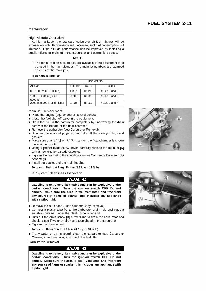
Main Jet Replacement
• Place the engine (equipment) on a level surface.
• Close the fuel shut off valve in the equipment.
• Drain the fuel in the carburetor completely by unscrewing the drainscrew at the bottom of the float chamber.
• Remove the carburetor (see Carburetor Removal).
• Unscrew the main jet plugs [C] and take off the main jet plugs andgaskets.
• Make sure that “L” [L] or “R” [R] mark on the float chamber is shownthe main jet position.
• Using a proper blade screw driver, carefully replace the main jet [D]with a new one for altitude expected.
• Tighten the main jet to the specification (see Carburetor Disassembly/Assembly).
• Install the gasket and the main jet plug.
Torque - Main Jet Plug: 19 N �m (1.9 kg �m, 14 ft �lb)
Fuel System Cleanliness Inspection
Gasoline is extremely flammable and can be explosive undercertain conditions. Turn the ignition switch OFF. Do notsmoke. Make sure the area is well-ventilated and free fromany source of flame or sparks; this includes any appliancewith a pilot light.
• Remove the air cleaner. (see Cleaner Body Removal)
• Connect a plastic tube [A] to the carburetor drain hole and place asuitable container under the plastic tube other end.
• Turn out the drain screw [B] a few turns to drain the carburetor andcheck to see if water or dirt has accumulated in the carburetor.
• Tighten the drain screw.
Torque - Drain Screw: 2.0 N �m (0.2 kg �m, 18 in �lb)
• If any water or dirt is found, clean the carburetor (see CarburetorCleaning), and fuel tank, and check the fuel filter.
Carburetor Removal
Gasoline is extremely flammable and can be explosive undercertain conditions. Turn the ignition switch OFF. Do notsmoke. Make sure the area is well- ventilated and free fromany source of flame or sparks; this includes any appliance witha pilot light.

2-12 FUEL SYSTEMCarburetor
• Remove:Air Cleaner and Related Parts (see Cleaner Body).
• Turn the fuel shut off valve to the OFF position.
• Drain the carburetor.
• Disconnect the fuel tube at the fuel inlet joint [A] of the carburetor.
• Remove the carburetor mounting bolts [B] and nuts [C].
• Disconnect the solenoid valve lead terminal and remove the earthterminal.
• Unhook the throttle link spring [B] at the throttle shaft lever [C] clipend with a long nose plier.
• Unhook the throttle [D] and choke link rods [E] at the top ends of theirarms while pull off the carburetor.
Carburetor Installation
• Clean the mating surfaces of the carburetor and intake manifold, andfit the new gaskets.
• Take care not to bend the throttle and choke link rods duringinstallation. Make sure the link spring around the throttle link rodis inplace and that it pulls the governor arm and carburetor throttleshaft lever toward each other.
• Install the intake manifold [A], new gaskets [B], insulator [C], carbu-retor [D] and intake pipe [E] sequence as shown.
• Tighten the carburetor mounting bolts and nuts.
Torque - Bolts and Nuts: 5.9 N �m (0.6 kg �m, 52 in �lb)
• Adjust:Carburetor Pilot ScrewIdle Speed

FUEL SYSTEM 2-13Carburetor
Carburetor Disassembly/Assembly
• Refer to the illustration shown for disassembly and assembly.
• There are several passage plugs (Ball plugs) in the carburetor body.Do not remove.
• Before disassembly, mark the outside of choke valve and throttlevalves for assembling them.
• Replace the pilot screw in accordance with the following procedure ifnecessary.
Carefully mark the position of the pilot screw limiter on the carburetorbody so that it can be installed and set to its original position later.
Remove the limiter. Be careful not to turn pilot screw at this point. Turn the pilot screw clockwise and count the number of turns until
screw is gently seated in the pilot passage. Record the number ofturns needed to closed the screw.
Turn out the pilot screw to replace it with anew one. Install the new pilot screw until the screw is gently seated. Then open
the screw the same number of turns as recorded prior to removal. Align the limiter with the mark on the carburetor body to install, taking
care not to turn the pilot screw.
• Install the choke valve and throttle valve on the shaft as the out sidemark of them facing outside, and apply a small amount of a bondngagent to the valve screw threads.
CAUTION
Do not apply too much bonding aent to the valve screws itselfmay be fixed.
• Drive the float pin so that it’s big diameter side faces the throttle shaftlever.
• The fuel inlet valve seat is pressed into the carburetor body and isnot replaceable.
• Assemble carburetor parts which recommended tightening torque.(see Exploded View)
1. Limiter 16. Gasket2. Pilot Screw 17. Pilot Jet3. Spring 18. Pilot Jet4. Screw 19. Plug, Main Jet5. Choke Valve 20. Gasket6. Choke Shaft 21. Main Jet (L)7. Seal 22. Main Jet (R)8. Screw 23. Gasket9. Throttle Valve 24. Solenoid Valve
10. Throttle Shaft 25. Screws11. Collar 26. Spring12. Seal 27. Drain Screw13. Float Valve14. Pin15. Float

2-14 FUEL SYSTEMCarburetor
Carburetor Cleaning
Clean the carburetor in a well-ventilated area, and take carethat there is no sparks or flame anywhere near the workingarea; this includes any appliance with a pilot light. Becauseof the danger of highly flammable liquids, do not use gasolineor low flash-point solvents to clean the carburetors.
CAUTION
Do not use compressed air on an assembled carburetor, or thefloats may be crushed by the pressure.Remove as many rubber or plastic parts from the carburetoras possible before cleaning the carburetor with a cleaningsolution. This will prevent damage to or deterioration of theparts.The carburetor body has plastic parts that cannot be removed.Do not use a strong carburetor cleaning solution which couldattack these parts; instead, use a mild high flash-point clean-ing solution safe for plastic parts.Do not use wire or any other hard instrument to clean carbu-retor parts, especially jets, as they may be damaged.
• Disassemble the carburetor.
• Immerse all the metal parts in a carburetor cleaning solution.
• Rinse the parts in water and dry them with compressed air.
• Do not use rags or paper to dry parts. Lint may plug the holes orpassages.
• Blow air through the holes and fuel passages with the compressedair. All holes must be open.
• Assemble the carburetor.
Carburetor Inspection
Gasoline is extremely flammable and can be explosive undercertain. Turn the ignition switch OFF. Do not smoke. Makesure the area is well ventilated and free from any source offlame or sparks; this includes any appliance with a pilot light.
• Inspect the carburetor body for damage. Flange sealing surfacesshould be smooth and free of burns and nicks. Replace the gasket ifnecessary.
• Turn the throttle and choke shafts to check that the throttle and chokebutterfly valves move smoothly.If the valves do not move smoothly, replace the carburetor body and/or throttle shaft and choke shaft assembly.
• Check the gasket on the carburetor body.If the gasket is not in good condition, replace it.
• Check the other parts of the carburetor for wear or damage. Replacethe part if necessary.
• Clean and check the float level as follows.
CAUTION
Do not push down on the float during float level checking.

FUEL SYSTEM 2-15Carburetor
• With the float [A] assembly installed onto the carburetor body [B], holdthe carburetor upside down at eye level. Gently support the float witha finger and bring it down slowly so that the float arm tab [C] justtouches the float valve needle [D]. The float lower surface [E] shouldbe parallel with the carburetor body mating surfaces [F].If the float position is not correct, replace it.
• Inspect the inlet needle valve for excessive wear or damage. The tipshould be smooth, without any grooves, scratches, or tears. The rodat the other end of the needle should move smoothly when push inand released.If either the needle or the seat is worn or damaged, replace the floatassembly and carburetor body as a set.
• Inspect the tapered portion [A] of the pilot screw [B] for wear ordamage.If the pilot screw is worn or damaged on the taper portion, replace it.
• Check the spring for weakened condition, replace it, if necessary.
Fuel Shut-Off Solenoid Valve Test
• Unscrew the fuel shut off valve and remove the valve.
• Connect a 12 VDC source to the solenoid as shown.If the actuate solenoid plunger (Needle Valve) does not pop in whenthe Test Voltage is applied, replace it.
NOTE If may be necessary to push the plunger slightly for the plunger to
withdraw.
2-16 FUEL SYSTEMIntake Manifold
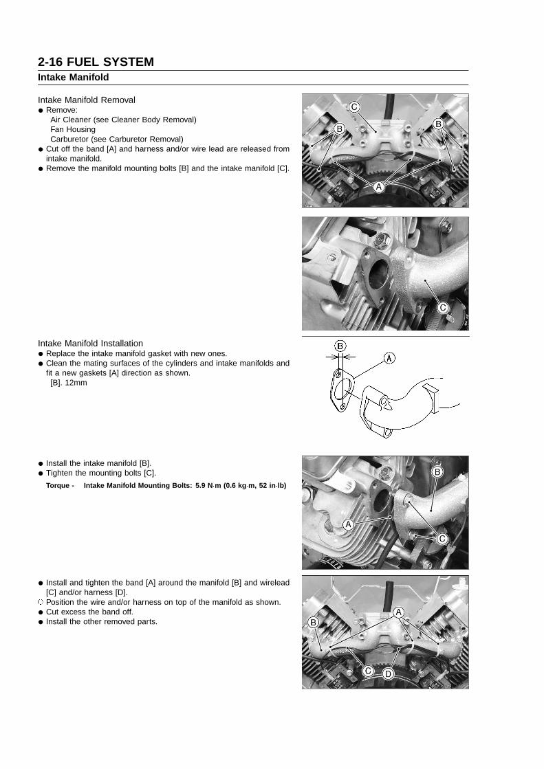
Intake Manifold Removal
• Remove:Air Cleaner (see Cleaner Body Removal)Fan HousingCarburetor (see Carburetor Removal)
• Cut off the band [A] and harness and/or wire lead are released fromintake manifold.
• Remove the manifold mounting bolts [B] and the intake manifold [C].
Intake Manifold Installation
• Replace the intake manifold gasket with new ones.
• Clean the mating surfaces of the cylinders and intake manifolds andfit a new gaskets [A] direction as shown.[B]. 12mm
• Install the intake manifold [B].
• Tighten the mounting bolts [C].
Torque - Intake Manifold Mounting Bolts: 5.9 N �m (0.6 kg �m, 52 in �lb)
• Install and tighten the band [A] around the manifold [B] and wirelead[C] and/or harness [D].
Position the wire and/or harness on top of the manifold as shown.
• Cut excess the band off.
• Install the other removed parts.

FUEL SYSTEM 2-17Intake Manifold
Intake Manifold Inspection
• Inspect the intake manifold for cracks or porous casting.
• Cracks not visible to the eye may be detected by coating thesuspected area with mixture of 25% kerosene and 75% light engineoil.
• Wipe the area dry and immediately apply a coating of zinc oxidedissolved in wood alcohol. If a cracks is present, the coating willbecome discolored at the defective area.If a crack is present in the intake manifold, replace it.
• Inspect the gasket surfaces for burns and nicks.

2-18 FUEL SYSTEMFuel Pump, Fuel Filter
The fuel pump cannot be disassembled, if any damage for the pumpis noticed replace it with a new one.
Fuel Pump Inspection
• Check the vent hole [A] and filter [B] for plugging or clogging.If vent hole and filter are plugged or clogged, remove the foreignmatter from them.
Fuel Flow Test:
Gasoline is extremely flammable and can be explosive undercertain conditions. Turn the ignition switch OFF. Do notsmoke. Make sure the area is well-ventilated and free fromany source of flame or sparks; this includes any appliancewith a pilot light.
• Disconnect the fuel pump outlet nozzle from the tube.
• Connect a suitable hose [A] to the outlet nozzle.
• Run the lower end of the hose into a container.
• Start the engine, Check the fuel flow.If fuel flow is none or little, replace the fuel pump.Check for clogged or damaged tubes and fuel filter. Replace the faultyparts.
Fuel Filter Inspection
• Visually inspect the fuel filter [A].If the filter is clear with no signs of dirt or other contamination, it isOK and need not be replaced.If the filter is dark or looks dirty, replace with a new one. Also checkthe rest of the fuel system for contamination.

FUEL SYSTEM 2-19Air Cleaner
Element Removal
• Remove the air cleaner cover nut [A] and the air cleaner cover [B].
• Remove:Foam Element [A]Paper Element [B]
Element Installation
• Install the element correctly on the air cleaner body.
• Be sure the paper element is in-place in the air cleaner body.
• Be sure the foam element is in-place on the paper element body.
Element Cleaning and Inspection
NOTE In dusty areas, the elements should be cleaned more frequently
than the recommended intervals.
Because of the danger of highly flammable liquids, do not usegasoline or a low flash-point solvent to clean the element.
• Remove the foam element and the paper element.
• Clean the foam element [A] in a bath of detergent and water, and letthe element air-dry throughly before install it.

2-20 FUEL SYSTEMAir Cleaner
• Clean the paper element [A] by tapping it gently on a flat surface toremove dust. If the element is very dirty, replace it with a new one.
CAUTION
Do not use compressed air to clean the paper element. Do notoil the paper or foam element.
Cleaner Body Removal
• Remove the elements. (see Element Removal)
• Remove the cleaner body mounting bolts [A], nuts [B], screws [C],and holder bracket [D].
• Do not miss rubber seal [E].
• Pull the breather tube [A] off the hole of the cleaner body [B].
Cleaner Body Installation
• Insert the breather tube [A] from the crankcase into the hole [B] ofthe cleaner body.
• Install the cleaner body on the intake pipe and bracket with mountingbolts, nuts and screws.
Torque - Cleaner Body Mounting Bolts and Nuts: 5.9 N �m (0.6 kg �m,52 in �lb)
Housing (Cover and Body) Inspection
• Clean the housing with detergent and water and dry thoroughly.
• Check the housing for deformation or other damage. The housingmust seal well and permit only filtered air to reach the carburetor.If the housing is damaged, it must be replaced.
• Check that no foreign material is obstructing the air passage.

COOLING SYSTEM 3-1
Cooling System
Table of Contents3
Exploded View....................................................................................................................................................................3-2Cooling Fan........................................................................................................................................................................3-3
Cooling Fan Removal..................................................................................................................................................3-3Cooling Fan Installation...............................................................................................................................................3-3Cooling Fan Inspection................................................................................................................................................3-3Screen Clearance Adjustment.....................................................................................................................................3-3

3-2 COOLING SYSTEMExploded View
T1: 2.0 N�m (0.2 kg�m, 18 in�lb)T2: 5.9 N�m (0.6 kg�m, 52 in�lb)T3: 6.9 N�m (0.7 kg�m, 61 in�lb)

COOLING SYSTEM 3-3Cooling Fan
Cooling Fan Removal
• Refer to Flywheel Removal in Electrical System chapter.
Cooling Fan Installation
• Refer to Flywheel Installation in Electrical System chapter.
Cooling Fan Inspection
• Visually inspect the blades [A] in the cooling fan [B].If they are any cracks, warps or damaged, replace the cooling fan.If any mud or dust have stuck to the cooling fan, clean it.
• Cooling fan is cleaned by washing in detergent and water.
CAUTION
Do not clean the cooling fan in oil solvent. It may be damageby oil solvent.
Screen Clearance Adjustment
• Check clearance between screen [A] and fan housing [B]. If clearanceis less than 1 mm, add proper number of spacer [C] between screenand bracket comp [D] to adjust clearance [G] 1 3 mm.F: ScrewsG: Clearance 1 3 mm

ENGINE TOP END 4-1
Engine Top End
Table of Contents4
Exploded View....................................................................................................................................................................4-2Specifications .....................................................................................................................................................................4-4Cylinder Head.....................................................................................................................................................................4-5
Compression Measurement ........................................................................................................................................4-5Cylinder Head Assembly Removal..............................................................................................................................4-6Cylinder Head Assembly Installation...........................................................................................................................4-6Push Rod Removal......................................................................................................................................................4-7Push Rod Installation ..................................................................................................................................................4-7Push Rod Inspection...................................................................................................................................................4-8Valve Mechanism Removal/Installation.......................................................................................................................4-8Cleaning and Inspection..............................................................................................................................................4-9
Valves...............................................................................................................................................................................4-10Valve Clearance Inspection.......................................................................................................................................4-10Valve Clearance Adjustment .....................................................................................................................................4-10Valve Seat Inspection................................................................................................................................................4-11Valve Seat Repair......................................................................................................................................................4-11Valve Head Thickness...............................................................................................................................................4-13Valve Stem Runout....................................................................................................................................................4-14Valve Stem Diameter.................................................................................................................................................4-14Valve Guide Inside Diameter.....................................................................................................................................4-14Valve Spring Inspection.............................................................................................................................................4-14
Cylinder, Piston ................................................................................................................................................................ 4-15Piston Removal..........................................................................................................................................................4-15Piston Installation ......................................................................................................................................................4-16Piston/Cylinder Seizure.............................................................................................................................................4-17Piston Cleaning ......................................................................................................................................................... 4-18Piston Ring and Ring Groove Wear..........................................................................................................................4-18Piston Ring End Gap.................................................................................................................................................4-19Piston Pin, Piston Pin Hole, and Connecting Rod Wear..........................................................................................4-19Piston Diameter.........................................................................................................................................................4-20Cylinder Inside Diameter...........................................................................................................................................4-20Cylinder Boring and Honing......................................................................................................................................4-20
Muffler...............................................................................................................................................................................4-22Muffler Removal.........................................................................................................................................................4-22Muffler Installation ..................................................................................................................................................... 4-22Inspection ..................................................................................................................................................................4-22

4-2 ENGINE TOP ENDExploded View
O: Apply engine oil.T1: 6.9 N�m (0.7 kg�m, 61 in�lb)T2: 9.8 N�m (1.0 kg�m, 87 in�lb)T3: 28 N�m (2.8 kg�m, 21 ft�lb)

ENGINE TOP END 4-3Exploded View
G: Apply grease.S: Follow the specific tightening sequence.
T1: 2.0 N�m (0.2 kg�m, 18 in�lb)T2: 5.9 N�m (0.6 kg�m, 52 in�lb)T3: 6.9 N�m (0.7 kg�m, 61 in�lb)T4: 28 N�m (2.8 kg�m, 21 ft�lb)T5: 22 N�m (2.2 kg�m, 16 ft�lb)

4-4 ENGINE TOP ENDSpecifications
Item Service Limit
Cylinder Head:
Cylinder compression (MIN) [390 kPa (57 psi)] (MIN)
Cylinder head warp 0.05 mm (0.002 in.)
Valves:
Valve head thickness Intake, Exhaust 0.35 mm (0.014 in.)
Valve stem runout Intake, Exhaust 0.05 mm (0.002 in.)
Valve stem diameter Intake 5.95 mm (0.0234 in.)
Exhaust 5.93 mm (0.0233 in.)
Valve guide inside diameter Intake, Exhaust 6.08 mm (0.239 in.)
Valve spring free length Intake, Exhaust 31.0 in (1.22 in.)
Rocker arm push rod rounout Intake, Exhaust 0.5 mm (0.02 in.)
Cylinder, Piston
Piston diameter 74.99 mm (2.952 in.)
Piston ring/groove clearance Top 0.18 mm (0.007 in.)
Second 0.16 mm (0.006 in.)
Piston ring thickness Top, Second 1.40 mm (0.055 in.)
Piston ring end gap Top 0.65 mm (0.026 in.)
Second 0.78 mm (0.031 in.)
Oil 1.05 mm (0.041 in.)
Piston pin outside diameter 15.96 mm (0.628 in.)
Piston pin hole inside diameter 16.08 mm (0.633 in.)
Connecting rod small end inside diameter 16.05 mm (0.632 in.)
Cylinder inside diameter: Standard Cylinder 75.28 mm (2.964 in.)
0.50 mm Oversize 75.78 mm (2.983 in.)
Cylinder bore out of round 0.056 mm (0.0022 in.)
Item Standard
Valve clearance Intake, Exhaust 0.075 to 0.125 mm (0.003 to 0.005 in.)
Valve seating surface angle Intake, Exhaust 45�
Valve seating surface width Intake 0.8 to 1.4 mm (0.03 to 0.06 in.)
Exhaust 1.1 to 1.6 mm (0.04 to 0.06 in.)
Valves guide inside diameter Intake, Exhaust 6.00 to 6.012 mm
(0.2362 to 0.2367 in.)
Cylinder bore diamter standard cylinder
Standard cylinder 75.18 to 75.20 mm
(2.960 to 2.961 in.)
0.50 mm Over size 75.68 to 75.70 mm
(2.979 to 2.980 in.)
Special Tools - Compression Gauge : 57001 - 221Compression Gauge Adapter M14 x 1.25: 57001–1159Piston Ring Pliers: 57001 - 115Piston Ring Compression Grip: 57001 - 1095Piston Ring Compression Belt, 67 - 79: 57001–1097Valve Seat Cutter Holder Bar: 57001–1128Valve Seat Cutter Holder, 6: 57001–1360Valve Seat Cutter, 45 � - 35.0 : 57001-1116Valve Seat Cutter, 30 � - 33.0 : 57001-1199Valve Seat Cutter, 30 � - 30.0 : 57001-1120Valve Seat Cutter, 45 � - 30.0 : 57001-1187

ENGINE TOP END 4-5Cylinder Head
Compression Measurement
• Before measuring compression, do the following. Be sure the battery is fully charged. Thoroughly warm up the engine so that engine oil between the piston
and cylinder wall will help seal compression as it does during normalrunning.
Stop the engine.
• Disconnect the spark plug caps of each cylinder and remove the sparkplugs.
• Attach the compression gauge assembly firmly into one plug hole.
Special Tool - Compression Gauge: 57001–221 [A]Compression Gauge Adapter: 57001–1159 [B]
• Ground the spark plugs to the engine.
To avoid fire, do not ground the spark plugs in proximity to theplug holes. Keep the plugs as far away as possible from theplug holes.
• Using the starter motor, turn the engine over with the throttle fullyopen until the compression gauge stops rising; the compression isthe highest reading obtainable.
Cylinder Compression (MIN) 390 kPa (57 psi)
• Repeat the measurement to the other cylinder.If the compression is higher than the specified value, the piston rings,cylinder and valves are probably in good condition.If the compression is too high, check the following.1. Carbon build-up on the piston crown and cylinder head - clean off
any carbon on the piston crown and cylinder head.2. Cylinder head gasket - use only the proper gasket. The use of a
gasket of incorrect thickness will change the compression.3. Valve guides and piston rings - rapid carbon accumulation in the
combustion chamber may be caused by worn valve guides and/or worn piston oil rings. This may be indicated by white exhaustsmoke.
If cylinder compression is lower than the (MIN), check the following:1. Gas leakage around the cylinder head - replace the damaged
gasket and check the cylinder head warp.2. Condition of the valve seating.3. Valve clearance.4. Piston/cylinder wear, piston seizure.5. Piston ring, piston ring groove.

4-6 ENGINE TOP ENDCylinder Head
Cylinder Head Assembly Removal
• Remove:Air Cleaner (see Fuel System chapter)Fan Housing (see Electrical System chpater)Muffler (see Muffler Exhaust Pipe Removal)Carburetor (see Fuel System chapter)Intake Manifold (see Fuel System chapter)Spark Plug
• Unscrew the rocker cover mounting bolts [A], and remove the cover[B] and gasket.
• When removing the #1, #2 cylinder head, set each cylinder at T.D.C[A] of power stroke in.
• Loosen the cylinder head bolts 1/4 turn in the sequence shown.
CAUTION
If the above procedure is not followed, the cylinder head maybe warped during removal.
• Repeat the sequence until all bolts are removed and lift off the cylinderhead assembly.
NOTE Mark the push-rods so they can be installed in their original position
during assembly.
Cylinder Head Assembly Installation
• Clean the mating surfaces of the cylinder heads and cylinder.
• Install the push rods in their original positions on each cylinder. (seePush Rod Installation).
• Install the knock pins.
• Set each cylinder at T.D.C [A] of power stroke in.
• Put a new gaskets and the cylinder head assemblies on each cylinder,then let the cylinder heads with push rods aligned under the rockerarms.
NOTE As the head gaskets are coated with sealing agents, be careful not
to damage the surfaces.
ENGINE TOP END 4-7Cylinder Head
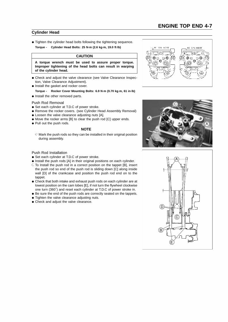
• Tighten the cylinder head bolts following the tightening sequence.
Torque - Cylinder Head Bolts: 25 N �m (2.6 kg �m, 19.0 ft �lb)
CAUTION
A torque wrench must be used to assure proper torque.Improper tightening of the head bolts can result in warpingof the cylinder head.
• Check and adjust the valve clearance (see Valve Clearance Inspec-tion, Valve Clearance Adjustment).
• Install the gasket and rocker cover.
Torque - Rocker Cover Mounting Bolts: 6.9 N �m (0.70 kg �m, 61 in �lb)
• Install the other removed parts.
Push Rod Removal
• Set each cylinder at T.D.C of power stroke.
• Remove the rocker covers. (see Cylinder Head Assembly Removal)
• Loosen the valve clearance adjusting nuts [A].
• Move the rocker arms [B] to clear the push rod [C] upper ends.
• Pull out the push rods.
NOTE Mark the push rods so they can be installed in their original position
during assembly.
Push Rod Installation
• Set each cylinder at T.D.C of power stroke.
• Install the push rods [A] in their original positions on each cylinder. To Install the push rod in a correct position on the tappet [B], insert
the push rod so end of the push rod is sliding down [C] along insidewall [D] of the crankcase and position the push rod end on to thetappet.
• Check that both intake and exhaust push rods on each cylinder are atlowest position on the cam lobes [E], if not turn the flywheel clockwiseone turn (360�) and reset each cylinder at T.D.C of power stroke in.
• Be sure the end of the push rods are correctly seated on the tappets.
• Tighten the valve clearance adjusting nuts.
• Check and adjust the valve clearance.

4-8 ENGINE TOP ENDCylinder Head
Push Rod Inspection
• Place the rocker arm push rod in V blocks that are as far apart aspossible, and set a dial gauge on the rod at a point halfway betweenthe blocks. Turn the rod to measure the runout. The differencebetween highest and the lowest dial readings is the amount of runout.If the runout exceeds the service limit, replace the rod.
Rocker Arm Push Rod RunoutService Limit: 0.5 mm (0.02 in.)
Valve Mechanism Removal/Installation
• Remove the cylinder head assembly. (see Cylinder Head AssemblyRemoval)
NOTE When removing the valve mechanism parts, note their position
so that they may be reinstalled in their original position duringassembly.
• Remove:Valve Clearance Adjusting Nuts [A]Rocker Arms [B]
• Support the valve head in the combustion chamber with a suitableblock.
• To remove the spring retainer [A], push down the spring retainer withthumbs and remove the collets [B].
• Remove the spring [C] and valve [D] .
• Remove the stem seals [A].
NOTE It is not necessary to remove the stem seal unless it is being
replaced. Valve guide [B] is not replaceable, do no remove it.

ENGINE TOP END 4-9Cylinder Head
• Valve Installation. Apply engine oil to the valve stem to avoid damaging the stem seal. Check to see that the valve moves smoothly up and down in the
guide. Check to see that the valve seats properly in the valve seat. If it does
not, repair the valve seat.
• Rocker Arm Installation Apply engine oil to the spherical pivot seat area on the rocker arm. Apply engine oil to the rocker arm where it touches the push rod and
valve stem end. Install the rocker arm on the stud bolt, and screw in the pivot and
locknut on the stud bolt temporarily.
NOTE Correct installation must be performed when adjusting the valve
clearance (see Valve Clearance Adjustment).
Cleaning and Inspection
• Scrape the carbon deposits from the head and exhaust port with asuitable tool [A].
To avoid gouging, use scrapers that are made of a material that willnot cause damage.
• Clean the head in a bath of high flash-point solvent and dry it withcompressed air.
Clean the cylinder head in a well-ventilated area, and take carethat there are no sparks or flame anywhere near the workingarea; this includes any appliance with a pilot light. Do notuse gasoline or a low flash-point solvent to clean the cylinderhead. A fire or explosion could result.
• Lay a straightedge [A] across the mating surface of the head at severaldifferent points, and measure warp by inserting a thickness gauge [B]between the straightedge and head.If warp exceeds the service limit, repair the mating surface. Replacethe cylinder head if the mating surface is badly damaged.
Cylinder Head WarpService Limit: 0.05 mm (0.002 in.)
• Check the cylinder head for cracks or other damage.
• Cracks not visible to the eye may be detected by coating thesuspected area with mixture of 25% kerosene and 75% light engineoil.
• Wipe the area dry and immediately apply a coating of zinc oxidedissolved in wood alcohol. If a cracks is present, the coating willbecome discolored at the defective area.
• If a cracks is present in the cylinder head, replace it.
• Inspect the mating surface for burrs and nicks.
• Clean and inspect the rocker arm where it touches the push rod andvalve stem.If the contact points [A] are worn or damaged, replace the rocker arm.
4-10 ENGINE TOP ENDValves
Valve Clearance Inspection
NOTE Valve clearance must be checked when the engine is cold (at room
temperature).
• Remove the rocker cover (see Cylinder Head Removal).
• Place the piston at top dead center (TDC) of the compression stroketurning the crankshaft clockwise facing the flywheel.
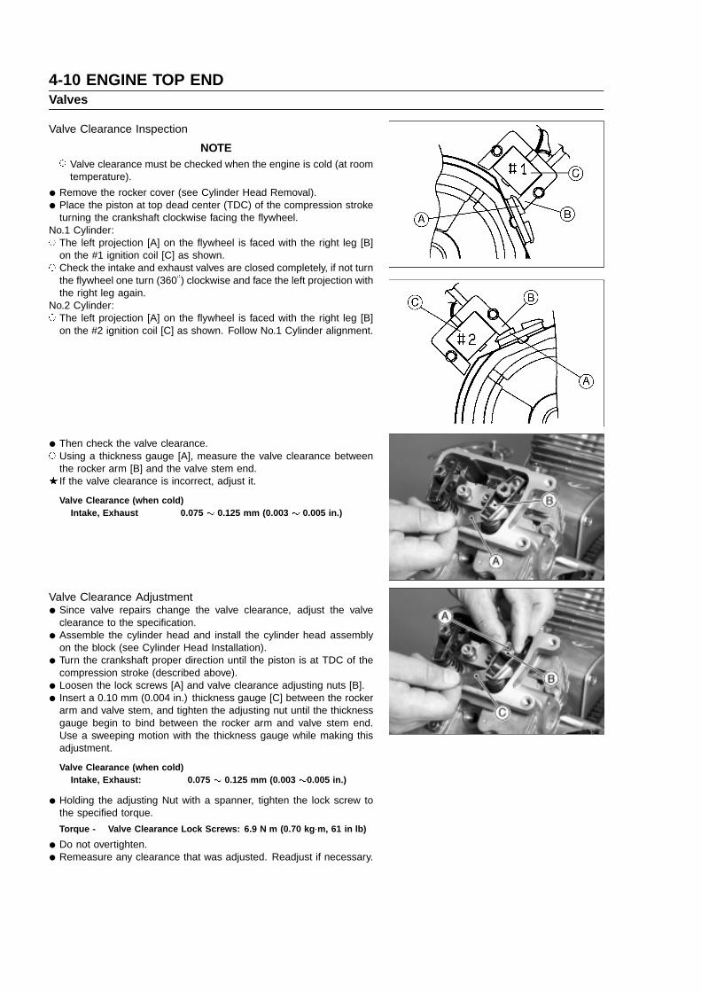
No.1 Cylinder: The left projection [A] on the flywheel is faced with the right leg [B]
on the #1 ignition coil [C] as shown. Check the intake and exhaust valves are closed completely, if not turn
the flywheel one turn (360�) clockwise and face the left projection withthe right leg again.
No.2 Cylinder: The left projection [A] on the flywheel is faced with the right leg [B]
on the #2 ignition coil [C] as shown. Follow No.1 Cylinder alignment.
• Then check the valve clearance. Using a thickness gauge [A], measure the valve clearance between
the rocker arm [B] and the valve stem end.If the valve clearance is incorrect, adjust it.
Valve Clearance (when cold)Intake, Exhaust 0.075 0.125 mm (0.003 0.005 in.)
Valve Clearance Adjustment
• Since valve repairs change the valve clearance, adjust the valveclearance to the specification.
• Assemble the cylinder head and install the cylinder head assemblyon the block (see Cylinder Head Installation).
• Turn the crankshaft proper direction until the piston is at TDC of thecompression stroke (described above).
• Loosen the lock screws [A] and valve clearance adjusting nuts [B].
• Insert a 0.10 mm (0.004 in.) thickness gauge [C] between the rockerarm and valve stem, and tighten the adjusting nut until the thicknessgauge begin to bind between the rocker arm and valve stem end.Use a sweeping motion with the thickness gauge while making thisadjustment.
Valve Clearance (when cold)Intake, Exhaust: 0.075 0.125 mm (0.003 0.005 in.)
• Holding the adjusting Nut with a spanner, tighten the lock screw tothe specified torque.
Torque - Valve Clearance Lock Screws: 6.9 N �m (0.70 kg �m, 61 in �lb)
• Do not overtighten.
• Remeasure any clearance that was adjusted. Readjust if necessary.

ENGINE TOP END 4-11Valves
Valve Seat Inspection
• Remove the valve. (see Valve Mechanism Removal/Installation)
• Inspect the valve seats for damage.If the seats are warped or distorted beyond reconditioning, replacethe cylinder head.
• Pitted or worn valve seats can be refaced. Lap the valves to the seatsafter refacing.
• Coat the valve seat with machinist’s dye.
• Push the valve into the guide.
• Rotate the valve against the seat with a lapping tool.
• Pull the valve out, and check the seating pattern on the valve head.It must be the correct width [A] and even all the way around.
NOTE The valve stem and guide must be in good condition or this check
will not be valid.
If the valve seating pattern is not correct, repair the seat.
Valve Seating Surface Width (STD)Inlet 0.8 1.4 mm (0.03 0.05 in.)Exhaust 1.1 1.6 mm (0.04 0.06 in.)
Valve Seat Repair
• Follow the manufacture’s instructions for use of valve seat cutters
Special ToolsIntake Valve:Seat Cutter 45 � - ø35.0 57001-1116Outside Cutter 30 �- ø33.0 57001-1199Exhaust Valve:Seat Cutter 45 �- ø30.0 57001-1187Outside Cutter 30 �- ø30.0 57001-1120Valve Seat Cutter Holder-ø6.0: 57001-1360Valve Seat Cutter Holder Bar: 57001-1128
If the manufacture’s instructions are not available, use the followingprocedure.
Seat Cutter Operating Cares:1. This valve seat cutter is designed only for valve seat repair.
Therefore the cutter must not be used for other purposes.2. Do not drop or hit the valve seat cutter, or the diamond particles
may fall off.3. Do not fail to apply engine oil to the valve seat cutter before
grinding the seat surface. Also wash off ground particles stickingto the cutter with washing oil.
NOTE Do not use a wire brush to remove the metal particles from the
cutter. It will take off the diamond particles.
4. Setting the valve seat cutter holder [A] in position, operate thecutter [B] with one hand [C]. Do not apply too much force to thediamond portion.
NOTE Prior to grinding, apply oil to the cutter, and during the operation
wash off any ground particles sticking to the cutter with washingoil.
5. After use wash the cutter with washing oil and apply a thin layerof engine oil before storing.

4-12 ENGINE TOP ENDValves
Marks Stamped on the Cutter:The marks stamped on the back of the cutter represent the following.
1 Cutter number, selected from 1 to 12
30� Cutter angle [A]
37.5� Outer diameter of cutter [B]
KS8B Manufactured lot number
Operating Procedures:
• Clean the seat area carefully.
• Recondition the valve seats with the valve seat cutters (45�, 30�) andlap the valves.
• Check the seats for good contact all the way around with machinist’sdye.
• Measure the seat width [A]. If it is more than the STD width, theseating surface should be refaced.
• If the valve seating pattern is not correct, repair the seat.
• Coat the seat with machinist’s dye.
• Fit a 45� cutter [A] to the holder and slide it into the valve guide. Resurface the valve seat with a 45� cutter, removing only enough
material to produce a smooth and concentric seat.
CAUTION
Do not grind the seat too much. Overgrinding will reducevalve clearance by sinking the valve into the head. If the valvesinks too far into the head, it will be impossible to adjust theclearance, and the cylinder head must be replaced. Do notturn the cutter counterclockwise or drop it against the seat, orit will be dulled.
• Use a 30� seat cutter [A] to narrow the seat width to the STD width. Turn the seat cutter one turn at a time while pressing down very lightly.
Check the seat width after each turn.
CAUTION
The 30� cutter removes material very quickly. Check the seatwidth frequently to prevent over grinding.
NOTE Keep the seat width as closely as possible to the STD width.
• Make a light pass with the 45� cutter to remove any possible burrs atthe edge of the seat.
• After resurfacing the seat, inspect for even valve seating. Apply a machinist’s dye to the valve face, insert the valve, and snap it
closed against the seat several times. The valve surface should showgood contact all the way around. Be sure the valve seat is centeredon the valve face. The position of the valve in the seat is evident afterlapping the valve.If the seat does not make proper contact, lap the valve into seat witha vacuum cap tool.

ENGINE TOP END 4-13Valves
• Coat the face of valve sparingly with a fine lapping compound.
• Use the vacuum cup tool [A], to grip top of the valve [B]. Rotate thevalve in a circular motion to lap the valve to the seat.
• Lift the valve slightly from the seat every 8 to 10 strokes, continuelapping operation until a uniform ring appears around entire surfaceof the valve face.
• When lapping is completed, wash all parts in solvent to removelapping compound. Dry the parts thoroughly.
• Note the position of the lapping mark on the valve face. The lappingmark should appear on or near the center of the valve face.
• When the engine is assembled, be sure to adjust the valve clear-ances. (see Valve Clearance Adjustment)
Valve Head Thickness
• Remove the valve (see Valve Mechanism Removal/Installation).
• Measure the thickness of the valve head.If the valve head thickness (valve margin) [A] is less than the servicelimit, replace the valve.
Valve Head ThicknessService Limit (IN, EX): 0.35 mm (0.014 in)

4-14 ENGINE TOP ENDValves
Valve Stem Runout
• Support the valve in V blocks at each end of the stem.
• Position a dial gauge perpendicular to the stem.
• Turn the valve and read the variation on the dial gauge.If the stem runout is greater than service limit, replace the valve.
Valve Stem RunoutService Limit (IN, EX): 0.05 mm (0.002 in.)
Valve Stem Diameter
• Measure the diameter of the valve stem [A] in two directions at rightangles, at four different positions on the stem.If any single measurement is less than the service limit, replace thevalve.
Valve Stem DiameterService Limit:Intake: 5.95 mm (0.234 in.)Exhaust: 5.93 mm (0.233 in.)
Valve Guide Inside Diameter
• Use a small bore gauge or a micrometer to measure the insidediameter [A] of the valve guide [B] a three places down the lengthof the guide.If the measurement is more than the service limit, replace the cylinderhead with a new one.
Valve Guide Inside DiameterService Limit:
Intake, Exhaust 6.08 mm (0.239 in.)
Valve Spring Inspection
• Inspect the valve spring for pitting, cracks, rusting, and burns.Replace the spring if necessary.
• Measure the free length [A] of the spring.If the measurement is less than the service limit, replace the spring.
Valve Spring Free LengthService Limit: 31.0 mm (1.22 in.)
ENGINE TOP END 4-15Cylinder, Piston
Piston Removal
• Split the crankcase (see Camshaft/Crankshaft chapter).
• Remove the camshaft (see Camshaft/Crankshaft chapter).
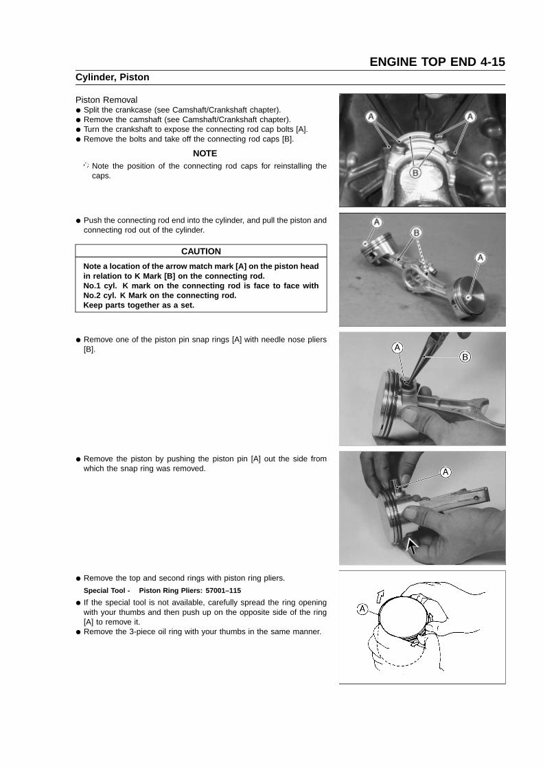
• Turn the crankshaft to expose the connecting rod cap bolts [A].
• Remove the bolts and take off the connecting rod caps [B].
NOTE Note the position of the connecting rod caps for reinstalling the
caps.
• Push the connecting rod end into the cylinder, and pull the piston andconnecting rod out of the cylinder.
CAUTION
Note a location of the arrow match mark [A] on the piston headin relation to K Mark [B] on the connecting rod.No.1 cyl. K mark on the connecting rod is face to face withNo.2 cyl. K Mark on the connecting rod.Keep parts together as a set.
• Remove one of the piston pin snap rings [A] with needle nose pliers[B].
• Remove the piston by pushing the piston pin [A] out the side fromwhich the snap ring was removed.
• Remove the top and second rings with piston ring pliers.
Special Tool - Piston Ring Pliers: 57001–115
• If the special tool is not available, carefully spread the ring openingwith your thumbs and then push up on the opposite side of the ring[A] to remove it.
• Remove the 3-piece oil ring with your thumbs in the same manner.

4-16 ENGINE TOP ENDCylinder, Piston
Piston Installation
• Install the expander [A] in the piston oil ring groove so that theexpander ends [B] touch together, never overlap.
• Install the upper and lower steel rails. There is no UP or Down to therails. They can be installed either way.
• Do not mix up the top and second rings.
• Install the second and top rings as shown.The rings should turn freely in the grooves.[A] Piston Head[B] Top Ring[C] Second Ring
• Align the piston and rings with the piston ring end gap as shown.[A]. Arrow Match Marks[B]. Top ring End Gap, Upper Steel Rail End Gap[C]. 30� 45�
[D]. Second Ring End Gap, Lower Steel Rail End Gap
• Apply engine oil to the piston pins.Assemble the pistons onto the connecting rods as follow:No.1 cyl. Piston, align the arrow match mark on the piston head with
opposite the raised letters (K Mark) on the connecting rod.No.2 cyl. piston, align the arrow match mark on the piston head with
K Mark on the connecting rod.[A]. No.1 Cyl. Piston[B]. No.2 Cyl. Piston[C]. Arrow Match Marks[D]. K Mark[E]. Opposite K Mark
• When installing a piston pin snap ring, compress it only enough toinstall it and no more.
Fit a new piston pin snap ring into the side of the piston so that thering opening [A] does not coincide with the notch [B] in the edge of thepiston pin hole.
CAUTION
Do not reuse the snap rings, as removal weakens and deformsthem. They could fall out and score the cylinder wall.

ENGINE TOP END 4-17Cylinder, Piston
• Apply engine oil to the piston skirt and the cylinder bore.Using the piston ring compressor grip [A] and the belt [B], lightly tapthe top of the piston with a plastic mallet [C] to insert the piston andconnecting rod into the cylinder.
Special Tool - Piston Ring Compressor Grip: 57001–1095Piston Ring Compressor Belt: 57001–1097
• Insert the piston and connecting rod so that the arrow match mark[A] on the top of the piston is facing the flywheel side [B].
CAUTION
The connecting rod and the connecting rod big end cap aremachined at the factory in the assembled state, so they mustbe replaced together as a set.
• Apply engine oil to the inner surface [A] of the connecting rod big end[B] and caps [C].
• Install the connecting rod big end caps on their original position oneach connecting rod big ends.
• Apply a small amount of engine oil to the thread [D] and seatingsurface [E] of the cap bolts.
• Tighten the cap bolts.
Torque - Connecting Rod Big End Cap Bolts: 9.8 N �m (1.0 kg �m, 87in �lb)
• Install:
• Camshaft (see Camshaft/Crankshaft chapter)
• Crankcase Cover (see Camshaft/Crankshaft chapter)
Piston/Cylinder Seizure
• In case of seizure, remove the piston.
• Visually inspect the cylinder and piston damage.If there is only light damage, smooth the position with #400 emerycloth. Remove the small aluminum deposits from the cylinder with#400 emery cloth or light honing.If the damage is severe, the both cylinders must be bored oversizeand oversized pistons installed.
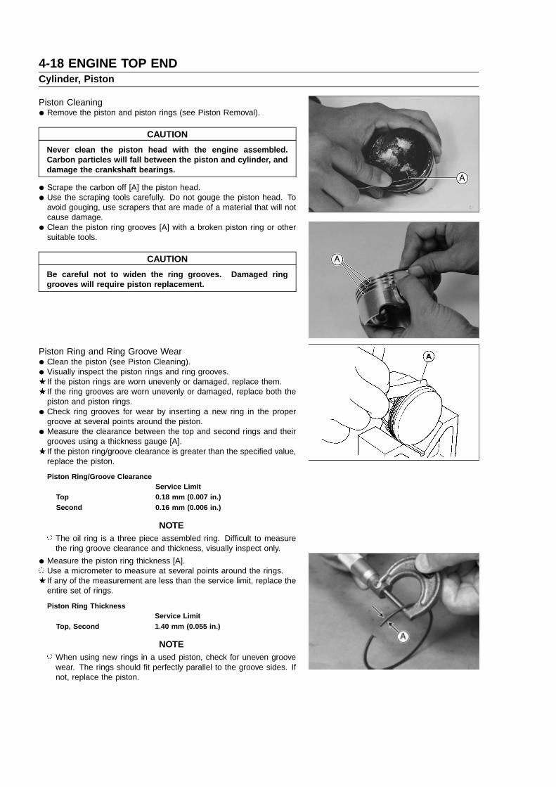
4-18 ENGINE TOP ENDCylinder, Piston
Piston Cleaning
• Remove the piston and piston rings (see Piston Removal).
CAUTION
Never clean the piston head with the engine assembled.Carbon particles will fall between the piston and cylinder, anddamage the crankshaft bearings.
• Scrape the carbon off [A] the piston head.
• Use the scraping tools carefully. Do not gouge the piston head. Toavoid gouging, use scrapers that are made of a material that will notcause damage.
• Clean the piston ring grooves [A] with a broken piston ring or othersuitable tools.
CAUTION
Be careful not to widen the ring grooves. Damaged ringgrooves will require piston replacement.
Piston Ring and Ring Groove Wear
• Clean the piston (see Piston Cleaning).
• Visually inspect the piston rings and ring grooves.If the piston rings are worn unevenly or damaged, replace them.If the ring grooves are worn unevenly or damaged, replace both thepiston and piston rings.
• Check ring grooves for wear by inserting a new ring in the propergroove at several points around the piston.
• Measure the clearance between the top and second rings and theirgrooves using a thickness gauge [A].If the piston ring/groove clearance is greater than the specified value,replace the piston.
Piston Ring/Groove ClearanceService Limit
Top 0.18 mm (0.007 in.)Second 0.16 mm (0.006 in.)
NOTE The oil ring is a three piece assembled ring. Difficult to measure
the ring groove clearance and thickness, visually inspect only.
• Measure the piston ring thickness [A]. Use a micrometer to measure at several points around the rings.
If any of the measurement are less than the service limit, replace theentire set of rings.
Piston Ring ThicknessService Limit
Top, Second 1.40 mm (0.055 in.)
NOTE When using new rings in a used piston, check for uneven groove
wear. The rings should fit perfectly parallel to the groove sides. Ifnot, replace the piston.

ENGINE TOP END 4-19Cylinder, Piston
Piston Ring End Gap
• Remove the piston rings.
• Push each ring (one at a time) in the cylinder bore to a point closeto the bottom of the cylinder bore.
Use the piston to push it in to be sure it is square.
• Measure the gap [A] between the ends of the ring [B] with a thicknessgauge.If the end gap of any ring is greater than the service limit, replace theentire set of rings.
Piston Ring End GapService Limit
Top 0.65 mm (0.026 in.)Second 0.78 mm (0.031 in.)Oil 1.05 mm (0.041 in.)
Piston Pin, Piston Pin Hole, and Connecting Rod Wear
• Remove the piston pin.
• Measure the diameter of the piston pin with a micrometer at severalpoints.If the outside diameter is less than service limit, replace the pistonpin.
Piston Pin Outside DiameterService Limit: 15.96 mm (0.628 in.)
• Measure the inside diameter [A] of the piston pin hole at several pointson both side. Use a dial bore gauge.If the inside diameter is more than the service limit, replace the piston.
Piston Pin Hole Inside DiameterService Limit: 16.08 mm (0.633 in.)
• Measure the inside diameter [A] of the small end of the connectingrod at several points. Use a dial bore gauge.If the inside diameter is more than the service limit, replace theconnecting rod.
Connecting Rod Small End Inside DiameterService Limit: 16.05 mm (0.632 in.)

4-20 ENGINE TOP ENDCylinder, Piston
Piston Diameter
• Measure the outside diameter of the piston 12.5 mm (0.9 in.) up fromthe bottom of the piston at a right angle to the direction of the pistonpin hole.If the measurement is less than the service limit, replace the piston.
Piston DiameterService Limit: 74.99 mm (2.952 in.)
Cylinder Inside Diameter
• Clean and measure the cylinder inside diameter. Use a dial bore gauge to measure front-to-back and side-to-side at
the points shown figure.If any of the cylinder bore measurements is greater than the servicelimit, the cylinder must be bored to the next oversize and then honed(see Cylinder Boring and Honing).
Cylinder Inside DiameterStandard: 75.18 mm 75.20 mm
(2.960 2.961 in.)Service Limit: 75.28 mm (2.964 in.)0.5 mm Oversize: 75.68 75.70 mm
(2.979 2.980 in.)Service Limit: 75.78 mm (2.983 in.)
Cylinder Bore Out-of-RoundStandard: 0.01 mm (0.0004 in.)Service Limit: 0.056 mm (0.0022 in.)
Cylinder Boring and HoningAlways resize to exactly 0.5 mm (0.02 in.) over the standard bore
size.If this is done accurately, the stock oversize rings and piston will fit
perfectly and proper clearance will be maintained.Resizing the cylinder bore can be done by reliable repair shop or by
using a drill press and honing tool.Use the stone recommended by the hone manufactures to produce
correct cylinder wall finish.Machine-bore first, the bore diameters should be shown in the table.
Fine Boring Bore Diameter
Oversize Bore Diameter0.50 mm 75.65 to 75.68 mm
(2.978 to 2.979 in.)
Final Bore Diameter
Oversize Bore Diameter0.50 mm 75.68 to 75.70 mm
(2.979 to 2.980 in.)

ENGINE TOP END 4-21Cylinder, Piston
Change to a honing stone for finishing, the final bore diameter shouldbe as shown in the table.Be sure the correct stone is used and the stone is not worn.
• Clean the cylinder at the top and bottom of the cylinder to removeburns and pieces of the base and head gasket.
• Anchor the cylinder (block) on the drill press table before honing.
• Align the center of the cylinder bore to the press center. Set the pressto operate from 200 to 250 rpm.
• Connect the drive shaft to the hone and set the stop on the drill pressso the hone can only extend 20 to 25 mm (3/4 to 1.0 in.) above thetop or below the bottom of the cylinder liner.
• Rotate the adjusting nut (knob) on the hone until the stones contactsnugly against the cylinder wall at the narrowest point. “Do not Force”.
• Turn the stone by hand. If you cannot turn it, the stone is too tight.Loosen the hone until it can be turned by hand.
• Be sure that the cylinder and hone are centered and aligned with thedrive shaft and drill spindle.
• Pour honing oil inside of the cylinder during the honing operation.Start the drill press. Move the hone up and down in the cylinderapproximately 20 cycles-per-minute.
• Check the diameter of the cylinder bore regularly during honing, usingan inside micrometer.
CAUTION
Stop the drill press before measuring and remove the honefrom the cylinder.
NOTE The finish should not be smooth, but have a 40 to 60 degree
crosshatch pattern.
• Hone the cylinder until it is about 0.007 to 0.009 mm (0.0003 to 0.0004in) large to allow for shrinkage when the cylinder cools.
NOTE Do not use gasoline, kerosene, or commercial solvent to clean the
cylinder bore. These fluids only wash all the oil from the cylinderwall. They do not remove the metal particles produced duringhoning.
• Clean the cylinder thoroughly. Use soap warm water and clean rags.Clean the cylinder wall for “white glove” inspection. A clean white ragshould not show soil from the cylinder wall.
• Dry the cylinder and coat with a engine oil.
CAUTION
The cylinder must be thoroughly cleaned after honing toeliminate all grit.
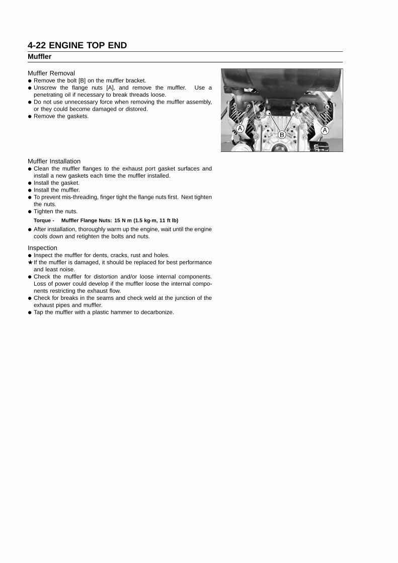
4-22 ENGINE TOP ENDMuffler
Muffler Removal
• Remove the bolt [B] on the muffler bracket.
• Unscrew the flange nuts [A], and remove the muffler. Use apenetrating oil if necessary to break threads loose.
• Do not use unnecessary force when removing the muffler assembly,or they could become damaged or distored.
• Remove the gaskets.
Muffler Installation
• Clean the muffler flanges to the exhaust port gasket surfaces andinstall a new gaskets each time the muffler installed.
• Install the gasket.
• Install the muffler.
• To prevent mis-threading, finger tight the flange nuts first. Next tightenthe nuts.
• Tighten the nuts.
Torque - Muffler Flange Nuts: 15 N �m (1.5 kg �m, 11 ft �lb)
• After installation, thoroughly warm up the engine, wait until the enginecools down and retighten the bolts and nuts.
Inspection
• Inspect the muffler for dents, cracks, rust and holes.If the muffler is damaged, it should be replaced for best performanceand least noise.
• Check the muffler for distortion and/or loose internal components.Loss of power could develop if the muffler loose the internal compo-nents restricting the exhaust flow.
• Check for breaks in the seams and check weld at the junction of theexhaust pipes and muffler.
• Tap the muffler with a plastic hammer to decarbonize.

LUBRICATION SYSTEM 5-1
Lubrication System
Table of Contents
5Exploded View....................................................................................................................................................................5-2Engine Oil Flow Chart........................................................................................................................................................5-3Specifications .....................................................................................................................................................................5-4Engine Oil and Oil Filter.....................................................................................................................................................5-5
Oil Level Inspection.....................................................................................................................................................5-5Oil Change...................................................................................................................................................................5-5Oil Filter Removal........................................................................................................................................................5-6Oil Filter Installation.....................................................................................................................................................5-6
Pressurized Lubrication System.........................................................................................................................................5-7Oil Pressure Measurement ........................................................................................................................................5-7Oil Pressure Switch Inspection ................................................................................................................................... 5-7
Oil Pump, Relief Valve........................................................................................................................................................5-8Oil Pump, Relief Valve Removal .................................................................................................................................5-8Oil Pump, Relief Valve Installation..............................................................................................................................5-8Oil Pump, Relief Valve Inspection...............................................................................................................................5-8
Oil Screen.........................................................................................................................................................................5-11Oil Screen Removal...................................................................................................................................................5-11Oil Screen Installation ............................................................................................................................................... 5-11Cleaning and Inspection............................................................................................................................................5-11

5-2 LUBRICATION SYSTEMExploded View
O: Apply engine oil.G: Apply grease.S: Follow the specific tighening sequence.
SS: Apply silicone sealant.
T1: 2.0 N�m (0.2 kg�m, 18 in�lb)T2: 5.9 N�m (0.6 kg�m, 52 in�lb)T3: 6.9 N�m (0.7 kg�m, 61 in�lb)T4: See page 5–6.T5: 25 N�m (2.6 kg�m, 19 ft�lb)T6: 9.8 N�m (1.0 kg�m, 87 in�lb)

LUBRICATION SYSTEM 5-3Engine Oil Flow Chart

5-4 LUBRICATION SYSTEMSpecifications
Item StandardEngine Oil:
Grade API Service Classification: SF, SG, SH, or SJ class
Viscosity SAE40, SAE30, SAE10W-30 / SAE10W-40, or SAE5W-20
Capacity 1.4 L (1.5 US qt) [When oil filter is not removed]
1.6 L (1.7 US qt) [When oil filter is removed]
Level Between "H" and "L" marks on oil gauge
Oil Pressure 241 to 310 kPa (35 to 45 psi)
Oil Pressure Switch:
Detect pressure 98 kPa (14.2 psi)
Screw PT 1/8 pipe thread
Oil Filter By-pass Valve Openning
Pressure 78.5 to 117.5 kPa (11.4 to 17.1 psi)
Item Service LimitOil Pump:
Inner and outer rotor clearance 0.2 mm (0.008 in.)
Outer rotor outside diameter 40.470 mm (1.5933 in.)
Outer rotor thickness 9.830 mm (0.3870 in.)
Pump housing inside diameter 40.801 mm (1.6063 in.)
Pump housing depth 10.230 mm (0.4028 in.)
Pump shaft outside diameter 10.923 mm (0.4300 in.)
Pump shaft bearing inside diameter 11.072 mm (0.4359 in.)
Relief valve spring free length 19.50 mm (0.77 in.)
Special Tool - Oil Filter Wrench : 57001–1249
Sealant - Kawasaki Bond (Silicone Sealant) : 56019–120

LUBRICATION SYSTEM 5-5Engine Oil and Oil Filter
CAUTION
Engine operation with insufficient, deteriorated, or contami-nated engine oil will cause accelerated wear and may result inengine seizure and accident.Before starting the engine for the first time, add oil: The engineis shipped dry. Preoil the engine to force all air from theinternal oil passages and the oil filter.
• Fill fresh engine oil to the specified level (see Oil Level Inspection).
• Run the engine at slow speed 2 minutes.
• Stop the engine and check the oil level.
Oil Level Inspection
• Place the engine on a level surface and check the oil level.
• Clean area around oil gauge [A] before removing it.
• Remove the oil gauge and wipe it with a clean cloth.
• Insert the oil gauge into gauge hole [B] and let its plug firmly fit intothe gauge hole, then check the oil level.
• The oil level should be the operating range (between “H” line and “L”line) on the oil gauge.If the oil level is near or below the “L” line, remove the oil filler cap[C] and add enough engine oil to bring oil level to the “H” line.
CAUTION
Do not fill above the “H” line. Excess oil will cause a smokingcondition.
Use the same type and make of oil that is already in the engine.
NOTE If the engine oil type and make are unknown, use any brand of the
specified oil to top up the level in preference to running the enginewith the oil level low. Then at your earliest convenience, changethe oil completely.
If the oil level is too high, remove the excess oil by loosening the drainplug [D].
Oil Change
• Change the oil after first 8 hours of operation. Thereafter change oilevery 100 hours.
• Start and warm up the engine so the oil will drain easily. Stop theengine.
• Place the engine on a level surface.
• Place a suitable container under the engine.
• Remove the drain plug [A] and drain the oil.
Be careful of hot oil when drained. It may be hot enough toburn you severely.
• Check the O-ring [B] at the drain plug for damage. Replace the O-ring with a new one if it is damaged.If the oil drain plug joint is removed, tighten it.
Torque - Oil Drain Plug Joint (Plastic) :17 N �m (1.7 kg �m, 12.0 ft �lb)Oil Drain Plug Joint (Metal) :39 N �m (4.0 kg �m, 29 ft �lb)
• Install the drain plug with the O-ring and tighten it.
Torque - Oil Drain Plug (Plastic) :6.9 N �m (0.70 kg �m, 61 in �lb)Oil Drain Plug (Metal) :20 N �m (2.0 kg �m, 14.5 ft �lb)

5-6 LUBRICATION SYSTEMEngine Oil and Oil Filter
• Remove the oil filler cap and pour in the specified type and amountof oil.
Engine Oil :Grade: API Service Classification:
SF, SG, SH or SJ ClassViscosity: SAE40, SAE30, SAE10W-30/SAE10W-40, or
SAE5W-20Capacity: 1.4 L (1.5 US �qt)
[When oil filter is not removed]1.6 L (1.7 US�qt)[When oil filter is removed]
Level: Between "H" and "L" marks on oil gauge
NOTE Some increase in oil consumption may be expected when a multi
grade engine oil (10W-30/10W-40, 5W-20) is used. Check the oillevel frequently.
Oil Filter Removal
• Using a strap wrench or oil filter wrench [A], remove the oil filter [B].
Special Tool - Oil Filter Wrench : 57001–1249
When unscrewing the oil filter, place a suitable container beneath theoil drip tray to receive oil from the oil filter and oil passages in theengine. Turn the filter counterclockwise to remove it
Oil Filter Installation
• Apply light film of engine oil to the seal [A].
• Install new filter. Turn the filter until the seal contacts mounting surface [B] of the
engine. Then turn the filter BY HAND (S) 3/4 turn more.
• Run the engine at slow idle speed 2 minutes. Check for leaks aroundthe engine.
• Stop the engine. Check the oil level (see Oil Level Inspection).

LUBRICATION SYSTEM 5-7Pressurized Lubrication System
The engine lubrication circuit is a pressurized system consistingof a positive displacement pump which picks up oil through a filterscreen from the crankcase. The oil is pumped to a replaceable oilfilter cartridge, through the engine’s oil passages to lubricate internalcomponents, and return to the crankcase. A pressure relief valve isused between the oil pump and oil filter to relieve excessive oil pressureby returning excess oil to the crankcase (see Oil Flow Chart).
Oil Pressure Measurement
• Remove the oil pressure switch or oil passage plug from thecrankcase.
• Install an appropriately sized oil pressure gauge adapter [A] and oilpressure gauge [B].
• Run the engine and allow warm up completely.
• Run the engine at fast idle speed and read the oil pressure gauge.
• Stop the engine.
• Remove the oil pressure gauge and adapter.
• Apply silicone sealant to the threads of the pressure switch andtighten it, or tighten the plug.
Sealant - Kawasaki Bond (Silicone Sealant) : 56019–120
Torque - Oil Pressure Switch : 9.8 N �m (1.0 kg �m, 87 in �lb)Oil Passage Plug : 3.9 N �m (0.40 kg �m, 35 in �lb)
If the oil pressure is below the specification, inspect the oil pump andrelief valve.If the oil pump and relief valve are not at fault, inspect the rest of thelubrication system.
Oil Pressure241 to 310 kPa (35 to 45 psi)
Oil Pressure SwitchPT 1/8 (Taper Pipe Threads)
Oil Pressure Switch InspectionWhen the oil pressure falls below 98 kPa (14.2 psi), the oil pressure
switch activates the oil warning lamp to alert the operator or lubricatingproblem.
• To check the oil warning system, insert the switch key into the “OFF”position of the engine switch, then turn it to the “RUN” position. Thewarning light must be illuminated.
• When the engine is running be sure the warning light is “OFF”.If the warning light comes on, stop the engine immediately and checkthe oil level.
• When starting the engine, note the warning light on dash carefully.If the warning light is on in the started engine in spite of adequate oillevel, check the lead from the pressure switch to the warning light forshort circuit and/or check the pressure switch and replace damagedpart.If the light is not on at the moment of the engine switch operation,check all leads of the warning light circuit or bulb and replacedamaged parts.

5-8 LUBRICATION SYSTEMOil Pump, Relief Valve
Oil Pump, Relief Valve Removal
• Remove the crankcase cover (see Camshaft/Crankshaft chapter).
• Unscrew the mounting bolts and remove the oil pump parts assembly(pump gear, pump cover plate, pump shaft, pins and rotors).
• Take off the relief valve spring and ball.
• Disassemble the pump parts assembly.[A] Pin[B] Pump Gear[C] Mounting Bolts[D] Outer Rotor[E] Inner Rotor[F] Pump Shaft[G] Relief Valve Ball[H] Spring[I] Pump Cover Plate[J] 6 mm DIA Hole
Oil Pump, Relief Valve Installation
• Fill the rotor housing with engine oil for initial lubrication.
• Install the relief valve ball and spring in position, then install the pumpparts assembly in the crankcase cover.
NOTE When Installing the pump parts assembly, align the 6 mm DIA hole
[A] on the cover plate with center of the relief valve.
• Install the mounting bolts and tighten them.
Torque - Oil Pump Cover Plate Mounting Bolts : 5.9 N �m (0.60 kg �m,52 in �lb)
Oil Pump, Relief Valve Inspection
• Remove the oil pump (see Oil Pump, Relief Valve Removal).
• Visually inspect the pump gear, outer and inner rotor, and cover plate.If there is any damage or uneven wear, replace them.
Check the clearance [A] between the inner and outer rotor with afeeler gauge. Measure the clearance between the high point of theinner rotor and the high point of the outer rotor.If the measurement exceed the service limit, replace the rotors as aset.
Inner and Outer Rotor ClearanceService Limit: 0.2 mm(0.008 in.)
• Measure the outside diameter [A] of the outer rotor with a micrometerat several points.If the rotor diameter is less than the service limit, replace both theinner and outer rotor.
Outer Rotor Outside DiameterService Limit: 40.470 mm(1.5933 in.)
• Measure the thickness [B] of the outer rotor with a micrometer atseveral pointsIf the rotor thickness is less than the service limit, replace both theinner and outer rotor.
Outer Rotor ThicknessService Limit: 9.830 mm(0.3870 in.)

LUBRICATION SYSTEM 5-9Oil Pump, Relief Valve
• Measure the inside diameter [A] of the pump housing with a insidemicrometer at several points.If the inside diameter is more than the service limit, replace thecrankcase cover.
Pump Housing Inside DiameterService Limit: 40.801 mm(1.6063 in.)
• Measure the depth [B] of the pump housing with a depth micrometerat several points.If any of measurement is more than the service limit, replace thecrankcase cover.
Pump Housing DepthService Limit: 10.230 mm(0.4028 in.)
• Measure the outside [A] diameter of the pump shaft with a micrometerat several points.If the diameter is less than the service limit, replace the pump shaft.
Pump Shaft Outside DiameterService Limit: 10.923 mm(0.4300 in.)
• Measurer the inside diameter [A] of the pump shaft bearing in thecrankcase cover with a inside micrometer at several points.If the inside diameter is more than the service limit replace thecrankcase cover.
Pump Shaft Bearing Inside DiameterService Limit: 11.072 mm(0.4359 in.)
• Visually inspect the relief valve spring, steel ball and valve seat in thecrankcase cover.If any rough spots are found during above inspection, wash the valveclean with a high flash-point solvent and blow out any foreign particlesthat may be in the valve with compressed air.
Clean the parts in a well ventilated area, and take care thatthere is no spark or flame anywhere near the working areas.Because of the danger of highly flammable liquids, do not usegasoline or low flash-point solvents.

5-10 LUBRICATION SYSTEMOil Pump, Relief Valve
If cleaning does not solve the problem, replace the relief valve parts.If necessary, put the ball in position and lightly tap the ball with asuitable tools to form a perfect seat.
• Measure free length [A] of the spring with a vernier caliper.If the free length of the spring is less than the service limit, replacethe spring.
Relief Valve Spring Free LengthService Limit: 19.50 mm(0.77 in.)

LUBRICATION SYSTEM 5-11Oil Screen
Oil Screen Removal
• Remove the crankcase cover (see Camshaft/Crankcase chapter).
• Unscrew the mounting bolts [A] and remove the spacers [B] and pipe[C].
• Push [D] the oil screen with thumbs and remove it.
Oil Screen Installation
• Clean the oil screen thoroughly whenever it is removed for any reason.
• Insert the oil screen [A] into slots [B] in the pipe [C], and install thepipe on the crankcase cover with the mounting bolts and spacers.
Torque - Oil Screen Mounting Bolts: 5.9 N �m (0.60 kg �m, 52 in �lb)
Cleaning and Inspection
• Clean the oil screen with high flash-point solvent and remove anyparticles stuck to it.
Clean the screen in a well-ventilated area, and take care thatthere is no spark or flame anywhere near the working area.Because of the danger of highly flammable liquids, do not usegasoline or low flash-point solvents.
NOTE While cleaning the screen, check for any metal particles that might
indicate internal engine damage.
• Check the screen carefully for any damage: holes and broken wire.If the screen is damaged, replace it.


CAMSHAFT/CRANKSHAFT 6-1
Camshaft/Crankshaft
Table of Contents
6
Exploded View....................................................................................................................................................................6-2Specifications .....................................................................................................................................................................6-3Crankcase ..........................................................................................................................................................................6-4
Crankcase Cover Removal..........................................................................................................................................6-4Crankcase Cover Installation.......................................................................................................................................6-4Inspection ....................................................................................................................................................................6-5Cleaning.......................................................................................................................................................................6-6
Breather..............................................................................................................................................................................6-7Breather Valve Removal..............................................................................................................................................6-8Breather Valve Inspection............................................................................................................................................6-8Breather Valve Installation...........................................................................................................................................6-9
Camshaft, Tappet .............................................................................................................................................................6-10Camshaft, Tappet Removal .......................................................................................................................................6-10Camshaft, Tappet Installation....................................................................................................................................6-10Camshaft Disassembly..............................................................................................................................................6-11Camshaft Assembly...................................................................................................................................................6-11Camshaft Inspection..................................................................................................................................................6-11Camshaft Bearing/Journal Wear...............................................................................................................................6-11
Crankshaft, Connecting Rod............................................................................................................................................6-13Connecting Rod Removal..........................................................................................................................................6-13Connecting Rod Installation ......................................................................................................................................6-13Crankshaft Removal..................................................................................................................................................6-13Crankshaft Installation...............................................................................................................................................6-13Cleaning/Inspection ..................................................................................................................................................6-13Connecting Rod Bend/Twist ......................................................................................................................................6-13Connecting Rod Big End/Crankpin Width Wear ....................................................................................................... 6-14Connecting Rod Big End Bearing/Crankpin Wear....................................................................................................6-14Crankshaft Runout.....................................................................................................................................................6-15Crankshaft Main Journal/Wear..................................................................................................................................6-15Crankpin Resizing ..................................................................................................................................................... 6-15

6-2 CAMSHAFT/CRANKSHAFTExploded View
O: Apply engine oil.G: Apply grease.S: Follow the specific tightening sequence.
SS: Apply silicone sealant.T1: 2.0 N�m (0.2 kg�m, 18 in�lb)T2: 5.9 N�m (0.6 kg�m, 52 in�lb)T3: 9.8 N�m (1.0 kg�m, 87 in�lb)T4: 25 N�m (2.6 kg�m, 19 ft�lb)

CAMSHAFT/CRANKSHAFT 6-3Specifications
Item Service LimitCamshaft, Tappet:
Cam lobe height Intake 29.621 mm (1.166 in.)
Exhaust 29.621 mm (1.166 in.)
Camshaft journal diameter PTO side 15.985 mm (0.6293 in.)
Flywheel side 15.985 mm (0.6293 in.)
Camshaft bearing inside diameter Crankcase 16.136 mm (0.6352 in.)
Crankcase cover 16.136 mm (0.6352 in.)
Crankshaft, Connecting Rod:
Connecting rod bend 0.15/100 mm (0.006/3.94 in.)
Connecting rod twist 0.15/100 mm (0.006/3.94 in.)
Connecting rod big end width 20.45 mm (0.805 in.)
Crankpin width 43.1 mm (1.697 in.)
Connecting rod big end inside diameter 40.044 mm (1.5765 in.)
Crankpin Outside diameter 39.940 mm (1.5724 in.)
Crankshaft runout 0.05 mm (0.002 in.) TIR
Crankshaft journal diameter PTO side 39.896 mm (1.571 in.)
Flywheel side 39.896 mm (1.571 in.)
Crankcase:
PTO shaft bearing inside diameter Crankcase cover 40.15 mm (1.581 in.)
Crankshaft journal bearing inside diameter Crankcase 40.15 mm (1.581 in.)
Sealant - Kawasaki Bond (Silicone Sealant): 56019–120

6-4 CAMSHAFT/CRANKSHAFTCrankcase
Crankcase Cover Removal
• Set the engine on a clean surface while parts are being removed.
• Drain the oil (see Lubrication System chapter).
• Remove:Exhaust Pipe and Muffler (see Engine Top End chapter)Control Panel (see Fuel System chapter)Governor Arm (see Fuel System chapter)
• Unscrew the mounting bolts [A] and remove the crankcase cover [B]from the crankcase.
There are two knock pins on the crankcase mating surface. A woodenor plastic mallet may be used to gently tap loose the crankcase cover.
Crankcase Cover Installation
• Chip off the old gasket from the mating surfaces of the crankcase andcover.
• Using compressed air, blow out the oil passage in the crankcasecover.
• With a high flash-point solvent, clean off the mating surfaces of thecrankcase and cover, and wipe dry.
Clean the crankcase and cover in a well-ventilated area, andtake care that there are no sparks or flame anywhere near theworking area; this includes any appliance with a pilot light. Donot use gasoline or a low flash-point solvent to clean parts. Afire or explosion could result.
• Be sure to replace any oil seal removed with a new one. Install the oil seal so that the marks [A] face out. Pack some amount of a high temperature grease [B] into the space
between the seal lip [C] and dust lip [D]. Press in the new oil sealusing a press or suitable tools until it is flush with flange surface [E].Do not damage the seal lips.
• When replacing the oil seal [A] of the governor shaft, note thefollowing.
Install the oil seal into the crankcase cover [B] after the governor shaftis inserted in the cover, and so that the marks [C] face out.
The depth [D] is 0 2 mm (0 0.08 in.).
• When installing the governor shaft and plate in the crankcase cover,see Fuel System chapter.

CAMSHAFT/CRANKSHAFT 6-5Crankcase
• Check to see that the crankcase dowel pins [A] are in place on thecrankcase.
• Install the gasket [B] on the crankcase.
• Install the crankcase cover and tighten the crankcase cover boltsfollowing the tightening sequence shown.
Torque - Crankcase Cover Bolts: 25 N �m (2.6 kg �m, 19.0 ft �lb)
Do not turn one screw down completely before the others, as it maycause the crankcase cover to warp.
Inspection
• Measure the inside diameter [A] of the PTO shaft bearing on thecrankcase cover at several points. This bearing is not replaceable.Replace the crankcase cover if the inside diameter is more than theservice limit.
PTO Shaft Bearing Inside DiameterService Limit: 40.15 mm (1.581 in.)
• Measure the inside diameter [A] of the crankshaft journal bearingon the crankcase at several points. This bearing is not replaceable.Replace the crankcase if the inside diameter is more than the servicelimit.
Crankshaft Journal Bearing Inside DiameterService Limit: 40.15 mm (1.581 in.)

6-6 CAMSHAFT/CRANKSHAFTCrankcase
Cleaning
• Remove:Camshaft and Tappets (see Camshaft, Tappet Removal)Crankshaft (see Crankshaft Removal)
• Clean up the crankcase and cover with a high flash-point solvent, andblow out any foreign particles that may be in the pockets inside of thecrankcase with compressed air.
Clean the crankcase and cover in a well-ventilated area, andtake care that there is no spark or flame anywhere near theworking area. Because of the danger of highly flammableliquids, do not use gasoline or low flash-point solvents.

CAMSHAFT/CRANKSHAFT 6-7Breather
The function of the breather is to create a vacuum in the crankcase which prevents oil from being forced out of theengine through the piston rings, oil seals or gaskets. A sealed-type crankcase emission control system is used to eliminateblow-by gases. The blow-by gases are led to the breather chamber through the crankcase and the camshaft. Then, it isdrawn into the clean side of the air cleaner through the cylinder head and the hose and mixed with the clean air flow, andsubsequently coming into the combustion chamber through the carburetor and the intake manifold.
Oil is primarily separated from the gases while passing through the inside of the rocker chamber from the crankcase,and secondly separated from the gases in the breather chamber, and then returned back to the crankcase cover.

6-8 CAMSHAFT/CRANKSHAFTBreather
Breather Valve Removal
• Remove the bolts [A] and breather chamber cover [B].
• Remove the pipe [A].
• Remove the breather valve [B] unscrewing the mounting screws [A] atthe cam gear side of the crankcase (see Camshaft, Tappet Removal).
Breather Valve Inspection
• Visually inspect the reed valve [A] for breakage, hair cracks ordistortion, replace it if necessary.
• Visually inspect the back plate [B] for damage or rough contactsurface, replace it if necessary.
• Inspect the valve seating surface [C]. The surface should be free ofnicks or burrs.

CAMSHAFT/CRANKSHAFT 6-9Breather
Breather Valve Installation
• Be sure the drain hole [A] on the breather chamber does notaccumulate with slugs.
• Install the breather valve on the cam gear side of the crankcase (seeCamshaft, Tappet Removal).
Torque - Breather Valve Screws: 2.0 N �m (0.2 kg �m, 18 in �lb)
• Install a new gasket so the silicone bead side faces the crankcaseand the breather chamber cover, and tighten the bolts.
Torque - Breather Chamber Cover Bolts: 5.9 N �m (0.6 kg �m, 52 in �lb)
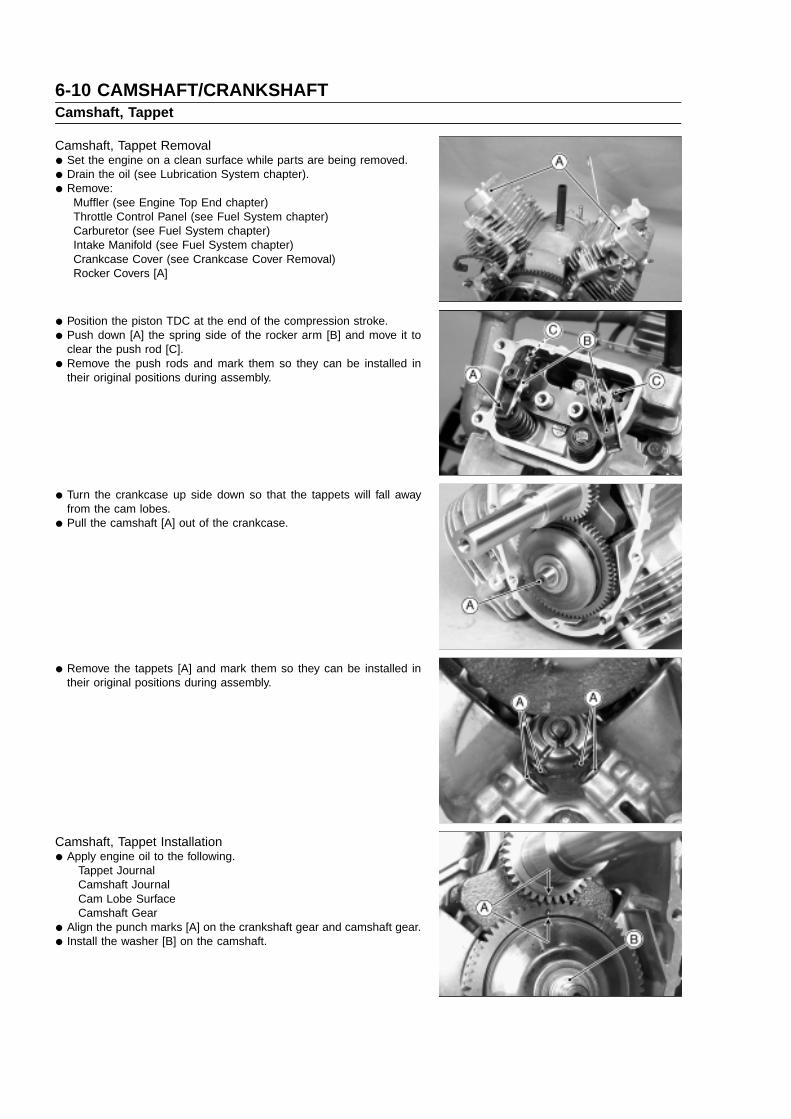
6-10 CAMSHAFT/CRANKSHAFTCamshaft, Tappet
Camshaft, Tappet Removal
• Set the engine on a clean surface while parts are being removed.
• Drain the oil (see Lubrication System chapter).
• Remove:Muffler (see Engine Top End chapter)Throttle Control Panel (see Fuel System chapter)Carburetor (see Fuel System chapter)Intake Manifold (see Fuel System chapter)Crankcase Cover (see Crankcase Cover Removal)Rocker Covers [A]
• Position the piston TDC at the end of the compression stroke.
• Push down [A] the spring side of the rocker arm [B] and move it toclear the push rod [C].
• Remove the push rods and mark them so they can be installed intheir original positions during assembly.
• Turn the crankcase up side down so that the tappets will fall awayfrom the cam lobes.
• Pull the camshaft [A] out of the crankcase.
• Remove the tappets [A] and mark them so they can be installed intheir original positions during assembly.
Camshaft, Tappet Installation
• Apply engine oil to the following.Tappet JournalCamshaft JournalCam Lobe SurfaceCamshaft Gear
• Align the punch marks [A] on the crankshaft gear and camshaft gear.
• Install the washer [B] on the camshaft.

CAMSHAFT/CRANKSHAFT 6-11Camshaft, Tappet
Camshaft Disassembly
• Remove the governor assembly (see Fuel System chapter).
• Remove:Spring [A]
Do not remove the ACR (automatic compression release) weight [B].
Camshaft Assembly
• Install the governor assembly (see Fuel System chapter).
• After assembling the camshaft, check the following items. The governor plate [A] must move freely. While shaking the camshaft, ACR weight [B] swings smoothly.
Camshaft Inspection
• Check the camshaft gear [A] for pitting, fatigue cracks, burrs or anevidence of improper tooth contact.Replace the shaft if necessary.
• Check the top of the cam lobes [B] for wear, burrs or uneven contact.Replace the shaft if necessary.
Camshaft Bearing/Journal Wear
• Measure the height of each cam lobe.If the cam height is less than the service limit for either lobe, replacethe camshaft.
Cam Lobe HeightService Limit: IN. 29.621 mm (1.166 in.)
EX. 29.621 mm (1.166 in.)

6-12 CAMSHAFT/CRANKSHAFTCamshaft, Tappet
• Measure both camshaft journals at several points around the journalcircumference.If the journal diameter is less than the service limit, replace thecamshaft.
PTO Side Camshaft Journal DiameterService Limit: 15.985 mm (0.6293 in.)
Flywheel Side Camshaft Journal DiameterService Limit: 15.985 mm (0.6293 in.)
• Measure the inside diameter [A] of the camshaft bearing on thecrankcase at several points. This bearing is not replaceable.Replace the crankcase if the inside diameter is more than the servicelimit.
Camshaft Bearing Inside Diameter (Crankcase)Service Limit: 16.136 mm (0.6352 in.)
• Measure the inside diameter [A] of the camshaft bearing on thecrankcase cover at several points. This bearing is not replaceable.Replace the crankcase cover if the inside diameter is more than theservice limit.
Camshaft Bearing Inside Diameter (Crankcase Cover)Service Limit: 16.136 mm (0.6352 in.)

CAMSHAFT/CRANKSHAFT 6-13Crankshaft, Connecting Rod
Connecting Rod Removal
• Remove:Piston (see Engine Top End Chapter)
Connecting Rod Installation
• Install:Piston (see Engine Top End chapter)
Crankshaft Removal
• Set the engine on a clean surface while parts are being removed.
• Drain the oil (see Lubrication System chapter).
• Remove:Flywheel (see Electrical System chapter)Camshaft (see Camshaft, Tappet Removal)Connecting Rod and Piston Assembly (see Engine Top End chapter)
• Pull the crankshaft [A] out of the crankcase. Tap gently with a woodenor plastic mallet if necessary to loosen the crankshaft.
Crankshaft Installation
• Clean up the crankshaft and crankcase thoroughly, especially at thebearing contact surfaces.
• Pack some amount of high temperature grease into the oil seal onthe crankcase.
• Apply engine oil to the journal and bearing.
• Carefully insert the crankshaft flywheel end into the main bearing andoil seal in the crankcase.
Cleaning/Inspection
• After removing, clean the crankshaft and connecting rods with a highflash-point solvent and dry them with compressed air.
• Inspect the teeth of the crankshaft gear for pitting, fatigue cracks,burrs and evidence of improper tooth contact.Replace the gear if necessary.
• Inspect the crankshaft and connecting rods especially at the bearingsurfaces for wear, scratches, evidence of improper contact or otherdamages.Replace them if necessary.
Connecting Rod Bend/Twist
• Measure connecting rod bend. Select an arbor of the same diameter as the connecting rod big end,
and insert the arbor through the connecting rod big end. Select an arbor of the same diameter as the piston pin and at least
100 mm long, and insert the arbor through the connecting rod smallend.
On a surface plate, set the big-end arbor on V blocks. With the connecting rod held vertically, use a height gauge to measure
the difference in the height of the small end arbor above the surfaceplate over a 100 mm length to determine the amount of connectingrod bend.If connecting rod bend exceeds the service limit, the connecting rodmust be replaced.
Connecting Rod BendService Limit: 0.15/100 mm (0.006/3.94 in.)
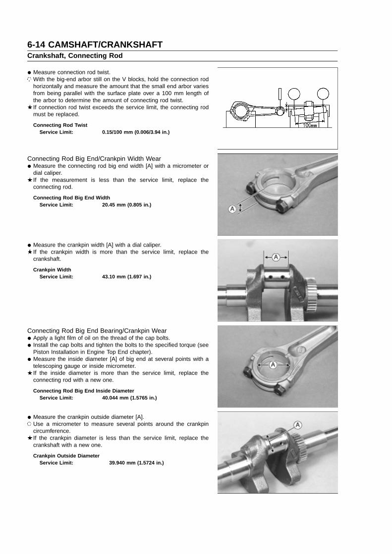
6-14 CAMSHAFT/CRANKSHAFTCrankshaft, Connecting Rod
• Measure connection rod twist. With the big-end arbor still on the V blocks, hold the connection rod
horizontally and measure the amount that the small end arbor variesfrom being parallel with the surface plate over a 100 mm length ofthe arbor to determine the amount of connecting rod twist.If connection rod twist exceeds the service limit, the connecting rodmust be replaced.
Connecting Rod TwistService Limit: 0.15/100 mm (0.006/3.94 in.)
Connecting Rod Big End/Crankpin Width Wear
• Measure the connecting rod big end width [A] with a micrometer ordial caliper.If the measurement is less than the service limit, replace theconnecting rod.
Connecting Rod Big End WidthService Limit: 20.45 mm (0.805 in.)
• Measure the crankpin width [A] with a dial caliper.If the crankpin width is more than the service limit, replace thecrankshaft.
Crankpin WidthService Limit: 43.10 mm (1.697 in.)
Connecting Rod Big End Bearing/Crankpin Wear
• Apply a light film of oil on the thread of the cap bolts.
• Install the cap bolts and tighten the bolts to the specified torque (seePiston Installation in Engine Top End chapter).
• Measure the inside diameter [A] of big end at several points with atelescoping gauge or inside micrometer.If the inside diameter is more than the service limit, replace theconnecting rod with a new one.
Connecting Rod Big End Inside DiameterService Limit: 40.044 mm (1.5765 in.)
• Measure the crankpin outside diameter [A]. Use a micrometer to measure several points around the crankpin
circumference.If the crankpin diameter is less than the service limit, replace thecrankshaft with a new one.
Crankpin Outside DiameterService Limit: 39.940 mm (1.5724 in.)

CAMSHAFT/CRANKSHAFT 6-15Crankshaft, Connecting Rod
Crankshaft Runout
• Measure the crankshaft runout. Set the crankshaft in a flywheel alignment jig or on V blocks gauge. Set a dial gauge against both bearing journals. Turn the crankshaft slowly to measure the runout. The difference
between the highest and lowest dial gauge readings (TIR) is theamount of runout.If the measurement exceeds the service limit, replace the crankshaft.
Crankshaft RunoutService Limit: 0.05 mm (0.002 in.) TIR
Crankshaft Main Journal/Wear
• Measure both main journals at several points around the journalcircumference.If the journal diameter is less than the service limit, replace thecrankshaft with a new one.
PTO Side Crankshaft Journal Diameter [A]Service Limit: 39.896 mm (1.571 in.)
Flywheel Side Crankshaft Journal Diameter [B]Service Limit: 39.896 mm (1.571 in.)
Crankpin ResizingCrankpin can be resized to accept 39.5 mm (1.5551 in.) dia under
size connecting rod. The crankpin should be reground if the crankpinis so much undersize and so much scored that a lapping operation willprove unsatisfactory. Reground can be done by a reliable repair shop.
• Before sending the crankshaft, inspect the crankpin for cracks.If any cracks, no matter how small, are found, the crankshaft must berejected.
• The final finishing dimensions should be shown in the table.
Finishing Dimensional Specifications
[A] 39.457 39.470 mm (1.5534 1.5539 in.)
[B] R 2.3 2.7 mm
[C] 43.0 mm MAX (1.693 in. MAX)
[D] 37.95 38.05 mm (1.4941 1.4980 in.)
• The crankpin surface should be concentric and parallel to each otherwithin 0.006 mm (0.0002 in.) full indicator reading.
• Finish the crankpin surface with a super finishing stone.


ELECTRICAL SYSTEM 7-1
Electrical System
Table of Contents
7
Exploded View....................................................................................................................................................................7-2Specifications .....................................................................................................................................................................7-3Wiring Diagram...................................................................................................................................................................7-4Precautions.........................................................................................................................................................................7-5Charging, Ignition System..................................................................................................................................................7-6
Flywheel, Stator Coil Removal....................................................................................................................................7-6Flywheel, Stator Coil Installation.................................................................................................................................7-7Charging System Operational Inspection....................................................................................................................7-9Stator Coil Resistance.................................................................................................................................................7-9Unregulated Stator Output ..........................................................................................................................................7-9Regulator Removal....................................................................................................................................................7-10Regulator Installation.................................................................................................................................................7-10Regulator Resistance................................................................................................................................................7-10Ignition Coil Removal.................................................................................................................................................7-13Ignition Coil Installation ............................................................................................................................................. 7-13Ignition Coil Inspection..............................................................................................................................................7-14Spark Plug Cleaning and Inspection.........................................................................................................................7-14Spark Plug Gap Inspection .......................................................................................................................................7-14
Starter System................................................................................................................................................................. 7-15Starter Motor Removal ..............................................................................................................................................7-15Starter Motor Installation...........................................................................................................................................7-15Starter Motor Disassembly........................................................................................................................................7-15Starter Motor Assembly ............................................................................................................................................7-16Starter Motor Brush Inspection.................................................................................................................................7-16Brush Spring Inspection............................................................................................................................................7-16Armature Inspection ..................................................................................................................................................7-16Yoke Assembly Inspection.........................................................................................................................................7-18Pinion Clutch Inspection............................................................................................................................................7-18

7-2 ELECTRICAL SYSTEMExploded View
G: Apply grease.SS: Apply silicone sealant.T1: 3.4 N�m (0.35 kg�m, 30 in�lb)T2: 5.9 N�m (0.6 kg�m, 52 in�lb)T3: 9.8 N�m (1.0 kg�m, 87 in�lb)T4: 15 N�m (1.5 kg�m, 11 ft�lb)T5: 19 N�m (1.9 kg�m, 14 ft�lb)T6: 22 N�m (2.2 kg�m, 16 ft�lb)T7: 56 N�m (5.7 kg�m, 41 ft�lb)

ELECTRICAL SYSTEM 7-3Specifications
Item Standard Service Limit
Charging System:
Regulated output voltage 14.1 V DC 15 V DC
Alternator stator coil resistance in the text – – –
Unregulated stator output 28.4 V AC/3000 rpm 26V AC/3000 rpm
Regulator resistance in the text
Ignition System:
Ignition coil:
Primary winding resistance in the text – – –
Secondary winding resistance 8 to 11 k – – –
Spark Plug CHAMPION RCJ8Y – – –
Plug gap 1.0 mm (0.040 in.) – – –
Electric Starter System:
Starter motor:
Carbon brush length (with spring boss) 12.7 mm (0.500 in.) 6.4 mm (0.250 in.)
Commutator groove depth (approx) 2.0 mm (0.078 in.) 0.9 mm (0.035 in.)
Commutator diameter 31.7 mm (1.250 in.) 31.1 mm (1.225 in.)
Commutator runout – – – 0.4 mm (0.016 in.)
Special Tool - Hand Tester: 57001–1394

7-4 ELECTRICAL SYSTEMWiring Diagram

ELECTRICAL SYSTEM 7-5Precautions
There are a number of important precautions that are musts whenservicing electrical systems. Learn and observe all the rules below. Do not reverse the battery lead connections. This will burn out the
diodes in the electrical parts. Always check battery condition before condemning other parts of an
electrical system. A fully charged battery is a must for conductingaccurate electrical system tests.
The electrical parts should never be struck sharply, as with a hammer,or allowed to fall on a hard surface. Such a shock to the parts candamage them.
To prevent damage to electrical parts, do not disconnect the batteryleads or any other electrical connections when the engine switch ison, or while the engine is running.
Because of the large amount of current, never keep the engine switchturned to the start position when the starter motor will not turn over,or the current may burn out the starter motor windings.
Take care not to short the leads that the directly connected to thebattery positive (−) terminal to the chassis ground.
Troubles may involve one or in some cases all items. Never replacea defective part without determining what CAUSED the failure. If thefailure was brought on by some other item or items, they too must berepaired or replaced, or the replacement part will soon fail again.
Make sure all connectors in the circuit are clean and tight, andexamine wires for signs of burning, fraying, etc. Poor wires and badconnections will affect electrical system operation.
Measure coil and winding resistance when the part is cold (at roomtemperature).
Electrical Connectors:
Female Connectors [A]
Male Connectors [B]

7-6 ELECTRICAL SYSTEMCharging, Ignition System
Flywheel, Stator Coil Removal
• Remove:Screws [B] and Screen [A]
• Loosen the fan housing bolts [A] and remove the fan housing [B].
• Remove:Bolts [A]Ignition Coils [B] (see Ignition Coil Removal)
• Hold the flywheel with a suitable tool [C], remove the flywheel bolt[B], washer, and bracket [A].
• Remove the bolts [A], plate [B] and fan [C].

ELECTRICAL SYSTEM 7-7Charging, Ignition System
• Using a suitable flywheel puller [A], remove the flywheel [B].
CAUTION
Always use flywheel puller.
• Remove:Woodruff Key [A]Screws [B]Stator Coil [C]
Flywheel, Stator Coil Installation
• Install the stator coil and tighten the screws.
Torque - Stator Coil Screws: 3.4 N �m (0.35 kg �m, 30 in �lb)
• Using a cleaning fluid, clean off any oil or dirt on the following portionsand dry them with a clean cloth.[A] Crankshaft Tapered Portion[B] Flywheel Tapered Portion
• Fit the woodruff key [C] securely in the slot in the crankshaft beforeinstalling the flywheel.
• Install the flywheel onto the crankshaft taper so that the woodruff keyfits in the key way in the hub of the flywheel.
• Install the fan [A] so that two positioning bosses [B] fit around flywheelignition magnet [C].
• Install the plate [D] so that the bosses [E] of the fan fit in the holes ofthe plate with bolts [F].
• Install the bracket [A] so that the notch [B] inserts into the slot [C] inthe flywheel.

7-8 ELECTRICAL SYSTEMCharging, Ignition System
• Fit the conical washer [A] onto the flywheel bolt [B], and tighten theflywheel bolt.
CAUTION
Make sure the direction of conical washer [A] for flywheel bolt[B]. Direction is as illustration.
Torque - Flywheel Bolt: 56 N �m (5.7 kg �m, 41 ft �lb)
[C] Bracket[D] Flywheel[E] Crankshaft
• Install the fan housing [A] and tighten the bolts [B] [C].
Torque - Fan Housing Bolts [B] (M8): 6.9 N �m (0.70 kg �m, 61 in �lb)Fan Housing Bolts [C] (M6): 5.9 N �m (0.60 kg �m, 52 in �lb)
• Install the screen [A] and tighten the screen bolts [B].
Torque - Screen Bolt: 5.9 N �m (0.60 kg �m, 52 in �lb)
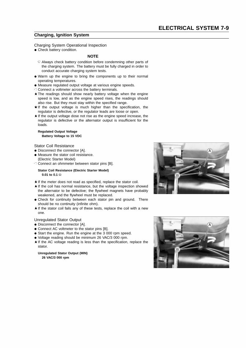
ELECTRICAL SYSTEM 7-9Charging, Ignition System
Charging System Operational Inspection
• Check battery condition.
NOTE Always check battery condition before condemning other parts of
the charging system. The battery must be fully charged in order toconduct accurate charging system tests.
• Warm up the engine to bring the components up to their normaloperating temperatures.
• Measure regulated output voltage at various engine speeds. Connect a voltmeter across the battery terminals.
The readings should show nearly battery voltage when the enginespeed is low, and as the engine speed rises, the readings shouldalso rise. But they must stay within the specified range.If the output voltage is much higher than the specification, theregulator is defective, or the regulator leads are loose or open.If the output voltage dose not rise as the engine speed increase, theregulator is defective or the alternator output is insufficient for theloads.
Regulated Output VoltageBattery Voltage to 15 VDC
Stator Coil Resistance
• Disconnect the connector [A].
• Measure the stator coil resistance.(Electric Starter Model)
Connect an ohmmeter between stator pins [B].
Stator Coil Resistance (Electric Starter Model)0.01 to 0.1
If the meter does not read as specified, replace the stator coil.If the coil has normal resistance, but the voltage inspection showedthe alternator to be defective; the flywheel magnets have probablyweakened, and the flywheel must be replaced.
• Check for continuity between each stator pin and ground. Thereshould be no continuity (infinite ohm).If the stator coil fails any of these tests, replace the coil with a newone.
Unregulated Stator Output
• Disconnect the connector [A].
• Connect AC voltmeter to the stator pins [B].
• Start the engine. Run the engine at the 3 000 rpm speed.
• Voltage reading should be minimum 26 VAC/3 000 rpm.If the AC voltage reading is less than the specification, replace thestator.
Unregulated Stator Output (MIN)26 VAC/3 000 rpm

7-10 ELECTRICAL SYSTEMCharging, Ignition System
Regulator Removal
• Remove:Stator Coil Lead Connector [A]Regulator Screw [B]Regulator [C]
Regulator Installation
• Install the regulator and tighten the screws.
Torque - Regulator Screw: 3.4 N �m (0.35 kg �m, 30 in �lb)
Regulator Resistance
• Set the KAWASAKI Hand Tester selector switch to the R � 100
position.
• Connect the test leads to the points shown on the chart and read theresistance.
There are two(2) types of Regulator on FH engines as follows:(with out Charging Monitor Type …3 Blades)
NOTE Resistance value may vary with individual meters.

ELECTRICAL SYSTEM 7-11Charging, Ignition System
(With Charging Monitor type … 5 Blades)
If the resistance is not as specified replace the regulator.

7-12 ELECTRICAL SYSTEMCharging, Ignition System
This engine ignition is controlled by a solid state ignition assembly and requires no periodic maintenance except for thespark plugs.
The system consists of the following:Inductive Ignition AssembliesPermanent Magnet FlywheelSpark PlugsStop Switch
Ignition Theory of OperationMounted to the periphery of a flywheel are a pair of magnetic poles (south leading in clockwise rotation), generated by
a permanent magnet.By rotating the flywheel (magnetic poles) clockwise past the ignition module on a laminated core group, a voltage is
generated in the primary winding (L1).This generates a small bias current to flow through the control resistor (R1) to the base of (Q1). This base drive causes
the transistor to conduct (turns on) completing the primary circuit. Current flows from the high side of the primary windingthrough the transistor (collector to emitter) to ground.
The trigger sensor (TS1) senses the optimum time (peak current) to remove the base drive from the transistor (Q1).This abrupt “turning off” of the transistor causes an interruption in current flow which allows its associated flux collapse,and several hundred volts is induced through the primary winding (L1) inducing a very large voltage in the secondarywinding (L2). When the secondary voltage reaches several thousand volts the spark plug (SP) gap is ionized and ignitionoccurs. The placement of the trigger sensor internal to the ignition insures constant timing over speed and temperatureand prevents counterclockwise operation.
The diode (D1) in the ignition shut off circuit blocks inadvertent application of battery voltage, protecting the internalcomponents of the ignition. With the stop switch (SW) in the closed position primary voltage is routed to ground, preventingignition operation.

ELECTRICAL SYSTEM 7-13Charging, Ignition System
Ignition Coil Removal
• Remove:Fan Housing (see Flywheel, Stator Coil Removal)Spark Plug Cap [A]Stop Switch Lead Connector [B]Bolts [C]Ignition Coil [D]
Ignition Coil Installation
• Install ignition coil on crankcase so that the stop switch lead connector[B] face the screen, and tighten bolt (1) first, then bolt (2). Whiletightening bolts, adjust the ignition coil air gap [A] between the threelegs of ignition coil and the two pole-plates to the specified value.
Ignition Coil Air GapStandard: 0.2 0.4 mm (0.008 0.016 in.)
Torque - Ignition Coil Bolts: 5.9 N �m (0.6 kg �m, 52 in �lb)
NOTE Above procedure must be used to insure proper coil air gap is not
too large.
[A] Thickness Gauge[B] Bolts

7-14 ELECTRICAL SYSTEMCharging, Ignition System
Ignition Coil Inspection
• Remove the ignition coils (see Ignition Coil Removal).
• Measure the primary winding resistance as follows: Set the hand tester to the R � 1 k range.
Special Tool - Hand Tester: 57001–1394
Make the measurements shown in the table.Ignition Coil Primary Winding Resistance
CAUTION
Use only Tester 57001–1394 for this test. A tester other thanthe Kawasaki Hand Tester may show different readings.If a megger or a meter with a large-capacity battery is used,the ignition coil will be damaged.
• Measure the secondary winding resistance as follows: Set the hand tester to the � 1 k range. Connect the tester between the iron core [A] and plug cap terminal
[C].
Ignition Coil Secondary Winding Resistance:8 11 k
If the tester does not read as specified, replace the coil.
Spark Plug Cleaning and Inspection
• Carefully pull the plug cap from the spark plug, and remove the sparkplug.If the plug is oily or has carbon built up on it, clean the plug using ahigh flash-point solvent and a wire brush or other suitable tool.If the spark plug electrodes are corroded or damaged, or if theinsulator is cracked replace the plug. Use the standard spark plug orits equivalent.[A] Insulator[B] Center Electrode[C] Plug Gap[D] Side Electrode
Spark Plug Gap Inspection
• Measure the gap with a wire-type thickness gauge.If the gap is incorrect, carefully bend the side electrode with a suitabletool to obtain the correct gap.
Spark Plug GapStandard: 0.75 mm (0.030 in.)

ELECTRICAL SYSTEM 7-15Starter System
Starter Motor Removal
• Remove the mounting bolts [A] and pull the starter motor [B] from theengine.
Starter Motor Installation
• Clean the starter motor and engine mounting flanges to ensure goodelectrical contact and tighten the mounting bolts.
Torque - Starter Motor Mounting Bolts: 15 N �m (1.5 kg �m, 11.0 ft �lb)
Starter Motor Disassembly
• Remove:Through Bolts and Nuts [A]Brush Plate [B]York [C]Cap [D]
• While the collar [A] is pushing, remove the snap ring [B].
• Remove:Spring [A]Pinion Assembly [B]Washer [C]Bracket [D]Armature [E]
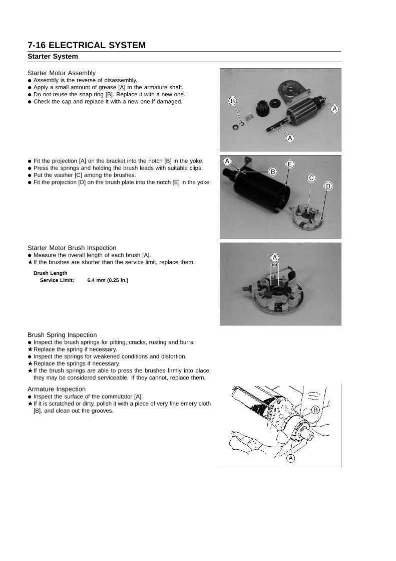
7-16 ELECTRICAL SYSTEMStarter System
Starter Motor Assembly
• Assembly is the reverse of disassembly.
• Apply a small amount of grease [A] to the armature shaft.
• Do not reuse the snap ring [B]. Replace it with a new one.
• Check the cap and replace it with a new one if damaged.
• Fit the projection [A] on the bracket into the notch [B] in the yoke.
• Press the springs and holding the brush leads with suitable clips.
• Put the washer [C] among the brushes.
• Fit the projection [D] on the brush plate into the notch [E] in the yoke.
Starter Motor Brush Inspection
• Measure the overall length of each brush [A].If the brushes are shorter than the service limit, replace them.
Brush LengthService Limit: 6.4 mm (0.25 in.)
Brush Spring Inspection
• Inspect the brush springs for pitting, cracks, rusting and burrs.Replace the spring if necessary.
• Inspect the springs for weakened conditions and distortion.Replace the springs if necessary.If the brush springs are able to press the brushes firmly into place,they may be considered serviceable. If they cannot, replace them.
Armature Inspection
• Inspect the surface of the commutator [A].If it is scratched or dirty, polish it with a piece of very fine emery cloth[B], and clean out the grooves.

ELECTRICAL SYSTEM 7-17Starter System
• Measure the depth of the grooves between the commutator segments.If the grooves are shallower than the specified limit, replace thearmature with a new one.If the grooves are only dirty, clean them carefully.
Commutator Groove Depth LimitLess than 0.9 mm (0.035 in.)
[A] Bad[B] Segment[C] Good[D] 0.9 mm (0.035 in.) limit[E] Mica
• Measure the commutator outside diameter [A] at several points.If the diameter is less than the service limit, replace the armature witha new one.
Commutator Outside DiameterService Limit: 31.1 mm (1.225 in.)
• Support the armature in an alignment jig at each end of the shaft asshown. Position a dial indicator perpendicular to the commutator.
• Rotate the armature slowly and read the commutator runout.F If runout is more than the service limit, turn down the commutator or
replace the armature with a new one.
Commutator RunoutService Limit: 0.4 mm (0.016 in.)
• Measure the armature winding resistance. Set the hand tester to the R � 1 range and measure the resistance
between each segment [A] and all the others.If the resistance it too high or even infinite, the armature winding hasan open circuit. Replace the starter motor.
Armature Winding ResistanceClose to 0
• Set the hand tester to the R � 1 k range and measure the resistancebetween the commutator and the armature shaft [B].If the resistance is less than infinite, the armature is shorted. Replacethe starter motor.
Commutator to Shaft Resistance(∞)
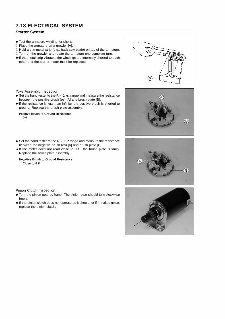
7-18 ELECTRICAL SYSTEMStarter System
• Test the armature winding for shorts. Place the armature on a growler [A]. Hold a thin metal strip (e.g., hack saw blade) on top of the armature. Turn on the growler and rotate the armature one complete turn.
If the metal strip vibrates, the windings are internally shorted to eachother and the starter motor must be replaced.
Yoke Assembly Inspection
• Set the hand tester to the R � 1 k range and measure the resistancebetween the positive brush (es) [A] and brush plate [B].If the resistance is less than infinite, the positive brush is shorted toground. Replace the brush plate assembly.
Positive Brush to Ground Resistance(∞)
• Set the hand tester to the R � 1 range and measure the resistancebetween the negative brush (es) [A] and brush plate [B].If the meter does not read close to 0 , the brush plate is faulty.Replace the brush plate assembly.
Negative Brush to Ground ResistanceClose to 0
Pinion Clutch Inspection
• Turn the pinion gear by hand. The pinion gear should turn clockwisefreely.If the pinion clutch does not operate as it should, or if it makes noise,replace the pinion clutch.

TROUBLESHOOTING 8-1
Troubleshooting
Table of Contents
8
Engine Troubleshooting Guide...........................................................................................................................................8-2Starter Motor Troubleshooting Guide.................................................................................................................................8-6

8-2 TROUBLESHOOTINGEngine Troubleshooting Guide
If the engine malfunctions, check if the way the engine is used is correct. If engine malfunctions even if engine is usedcorrectly, systematically carry out troubleshooting starting with simple points.
This chart describes typical troubleshooting procedures.Do not unnecessarily disassemble carburetor, magneto or engine unless it has been found to be the cause of
malfunctioning.
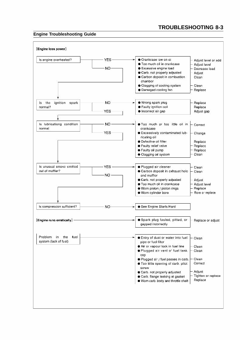
TROUBLESHOOTING 8-3Engine Troubleshooting Guide

8-4 TROUBLESHOOTINGEngine Troubleshooting Guide

TROUBLESHOOTING 8-5Engine Troubleshooting Guide
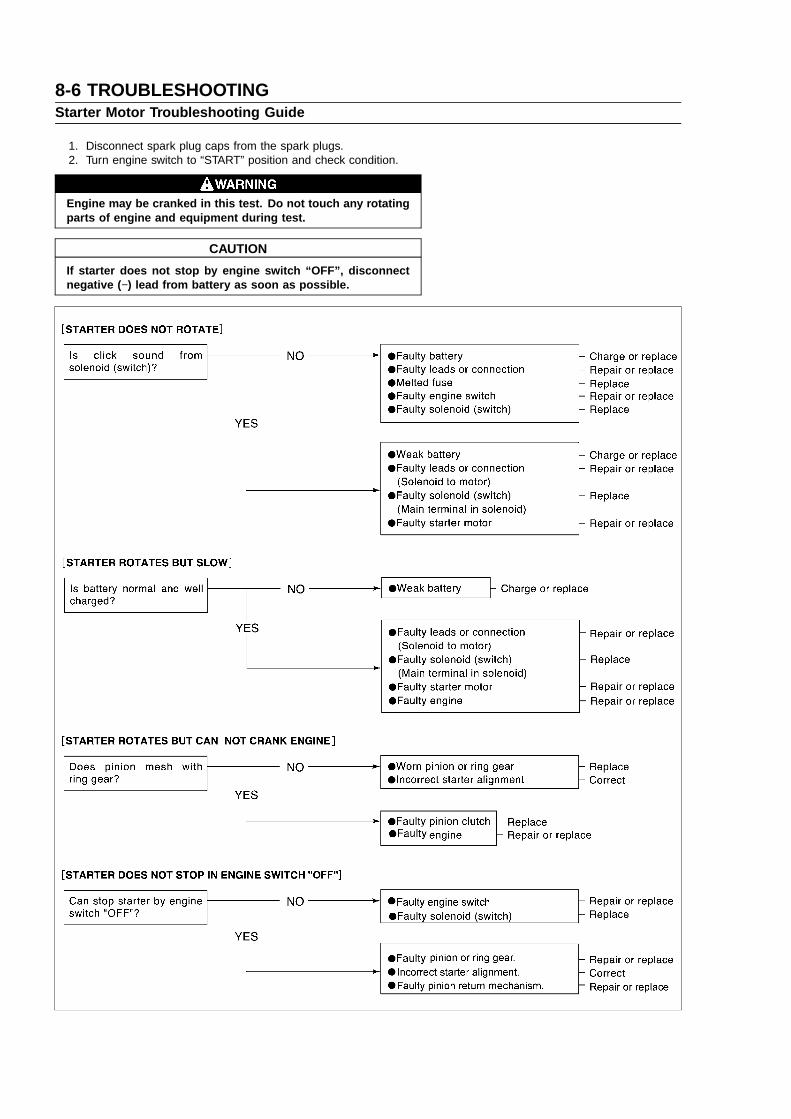
8-6 TROUBLESHOOTINGStarter Motor Troubleshooting Guide
1. Disconnect spark plug caps from the spark plugs.2. Turn engine switch to “START” position and check condition.
Engine may be cranked in this test. Do not touch any rotatingparts of engine and equipment during test.
CAUTION
If starter does not stop by engine switch “OFF”, disconnectnegative ( −) lead from battery as soon as possible.