4pe0 anti- craft manuals 3338, anti-aircraft ammuniti… · 11 appendices a. explosives and their...
TRANSCRIPT
R E S T R I C T E D
The information given irythit document is not to be communicated, either directlyior indirectly, to the Press or to any person not authorize^ to receive it.
WX). C o d e N o.
5 4 3 0
26/Manuals/3338
!
4 "Pe0*
Anti-*
•k
craft
/
By Command o f the Army Council
. c
WAR OFFICE, 1 5th August, 1949
________________ -

CONTENTS
1. INTRODUCTION
2. EXPLOSIVES
3. THE CARTRIDGE
4. THE PRO JECTILE
5. FUZES, GAINES, TRACERS, ETC.
6. D R IL L AMMUNITION
7. RECORDS
8. M ARKINGS
9. CARE, PRESERVATION AND PREPARATION
1.1 General . . . .
Page
I1.2 A.A. Equipments . I1-3 The Round of Ammunition . I1.4 Ammunition Categories 2
2.1 General . . . . 22.2 Propellants . . . . 32.3 High Explosives . 52.4 Miscellaneous Compositions . 92.5 Conclusions. . . . 10
3 -i Cartridge Case 113.2 Primer . . . . 113-3 Igniter . . . . • 133 4 Propellant Charge • 143-5 Decoppering Charge 14
4.1 General . . . . • 144. 2 S h e ll ........................................ • 154-3 Shot . . . . . . 18
5 -i General . . . . • 195.2 Fuzes . . . . . . 245-3 Gaines . . . . • 365 4 Tracers and Igniters • 36
6.1 General . . . . • 376.2 Cartridges . . . . • 376.3 Fuzes . . . . . ■ 38
7 -i Ammunition . 387.2 Gun . • 39
8.1 General . . . . • 4°8.2 Cartridge Case • 408.3 Primer . . . . • 4 i8.4 Projectile . . . . • 4 i8.5 Gaine or Auxiliary Detonator. • 438.6 Fuze and Plug • 438.7 Tracer and Tracer-Igniter • 448.8 Package . . . . • 44
9. 1 Packages . . . . • 459.2 Storage . . . . • 469-3 Preparation . . . . • 479 4 Routine Inspections at Gun Positions 529-5 Damaged and Defective Ammunition 529.6 Salvage . . . . • 54
11
APPENDICESA. Explosives and their Uses
Page ■ 55 G. Empty Components
Page69-71
B. Propellant Composition . . 56 H. Methods o f Filling 73-76C. Propellant Nomenclature • 57 I. Fuze, Tracer and Igniter Details • 77D. High Explosive Composition . 58 J . Package Details . . . . ■ 78E. Cartridges . . . . 59-67 K . Weights and Stowage Dimensions • 79F. Primer and Igniter Details 68
SUPPLEMENTSF .1 17 Fuze, Percussion, D .A ., No. 1 1 7
Page80-83 P .n Primer, Percussion, No. 1 1 .
Page ■ n o
F.208 Fuze, Time, Mechanical, No. 208 84-87 P .12 Primer, Percussion, No. 12 . . i ns000<sfa Mechanism, Tim e, 43 seconds . 88-92 P .17 Primer, Electric, No. 17 . 1 12F .2 14 Fuze, Time, Mechanical, No. 2 14 93-96 P.18 Primer, Percussion, No. 18 . . 1 1 3F .2I4M Mechanism, Time, Fuze No. 2 14 97-10 1 T . 1 1 Tracer and Igniter, No. 1 1 . . 1 14F.255 Fuze, Percussion, D .A ., No. 255 . 102-105 T .12 Tracer and Igniter, No. 12 . 1 1 5G .1 1 Gaine, No. 1 1 . 106-107 T .14 Tracer and Igniter, No. 14 . . 1 16 - 1 1 7P.9 Primer, Percussion, No. 9 . 108-109
ILLUSTRATIONSFig. Subject Page Fig. Subject Page
1. Propellant Shapes . . . . . 4 19- Fuze, Time, Mechanical, No. 208 . 262. Propellant Dimensions . . . . . 6 20. Clockwork Mechanism o f Time Fuzes 273. Use o f Initiators, Intermediaries and Bursters . 7 2 1. Escapement . . . . . . . 284. 3.7-inch Q.F. Case . . . . . 1 1 22. Fuze, No. 2 14 . . . . 295. Primer, Percussion, No. 1 12 23. V .T . Fuzes— Block diagram . . . . 326. Primer, Electric, No. 17 . . . . 13 24. V .T . Fuzes— Firing Circuit . . . . 327. Propellant Charge . . . . . . 14 25- V .T . Fuzes— Assembly . . . . . 338. H .E. S h e l l .................................................................. 15 26. V .T . Fuzes—No. T97 and T98 339. Shrapnel Shell . . . . . . 1 6 27. Fuze, Percussion, D .A ., No. 1 17 , Mk. 8 34
10. Practice Proj ecti l e. . . . . 1 7 28. Fuze, Percussion, D .A ., No. 255, Mk. 1 ■ 341 1 . Method o f Filling Tracer Cavity o f A.P. Shot . 18 29. Fuze, Base . . . . . . . 3512. Detonator . . . . . . . 1 9 30. Gaine, No. 1 1 3613 . Magazine . . . . . . 1 9 3 i- Tracer, Shell, No. 2, Mk. 7‘ . 3614. Fuze No. 199. Action on Shock o f Discharge 21 32. Tracer and Igniter, Shell, No. 12 , Mk. 2 . 3715 . Arming Sleeve, Centrifugal Balls and Ferrule . 21 33- Typical Exploder System for D.A. and Time16. Shutter . . . . . . . 22 Fuzes . . . . . . . 4917 . Combustion Time Fuze Rings 24 34- Typical Exploder System for V .T . and Time 4918. Fuse No. 199 . . . . . . 25 Fuzes . . . . . . .

m
INDEXN O TE: A decimal system is used for references.
For example, the “ Balance Arm ” entry in the Index is: 5.22352, meaning that the reference will be found in :
5 FUZES, GAINES, TRACERS, ETC.5.2 FU Z ES
5.22 Time Fuzes
5.223 Mechanical
5.2235 Escapement
5.22352 Balance Arm
A fullpoint (.) is placed after the number of the Main Heading.
To locate a paragraph or sub-paragraph:
Find the Index entry.
Turn to the PAGE referred to in the Index entry.
Find on the left-hand side of the column the F U L L N U M BER quoted in the Index, e.g. 5.22352 for “ Balance Arm ” .
Subject Page Reference Subject Page Reference
A Assemblies o f fuze mechanisms . 22 5.136“ A ” Primers, preparation . . . . 48 9.322 Assembly of V .T . fuzes . . . . 33 5-234A.A. equipments . . . . . 1 1.2 Auxiliary detonator . . . . . 32 5.2326A.P. shot . . . . . . . 18 4.322 33 33 . . . . . 36 5-3A.P.C. shot . . . . . . 18 4324 Azide, lead . . . . . . 8 2.322A.P.C .B.C. shot . . . . . 1 8 4-325A .S .A .......................................................................... 8 2.324 BAcceleration forces acting on fuzes 20 5.1322 Balance arm, mechanical time fuzes 28 5.22352Accidents . . . . . . . 52 9.521 Ball of primer gas check . . . . 1 2 3.2212Action sequence of mechanical time fuzes 3° 5.2238 Ballistic cap, A.P. shot . . . . 1 8 4 3 2 5Aerial, V .T . fuzes . . . . . 31 5.2321 „ „ mechanical time fuzes 25 5.2231Age, effect on propellant . . . . 3 2.22 Balls, centrifugal . . . . . 21 5-1343Amatol . . . . . . . 9 2.343 Band, driving . . . . . . 1 4 4-13Ammonium nitrate . . . . . 9 2.342 Bands on packages . . . . . 44 8.82
„ perchlorate . . . . 1 0 2.434 „ „ projectiles . . . . . 42 8.424Ammunition in bulk . . . . . 46 9.22 Barrel, mechanical time fuzes 25 5.22332
„ recesses . . . . . 52 9.42 Base of projectile . . . . . 1 4 4.12„ records . . . . . 38 7-1 Basic colours o f projectiles . . . . 42 8.421
Amplifier, V .T . fuzes . . . . . 32 5.2324 Batch label . . . . . . 45 8.845Antimony sulphide . . . . . 1 0 2-453 ,, number on packages . . . . 44 8.835Anvil o f fuze . . . . . . 20 5 . I3 3 I Batches . . . . . . . 38 7 .12Arbor, mechanical time fuzes 25 5.22332 Battery, V .T . fuzes . . . . . 31 5.2322Arming . . . . . . . 20 5 .13 1 Blank . . . . . . . 2 1.44
„ r i n g ...................................................... 22 5.136 Blinds . . . . . . . 53 9.524,, sleeve . . . . . . 21 5-1343 ,, destruction, disposal and removal 53 9.5242„ s p r in g ...................................................... 22 5.136 Blow-backs . . . . . . 53 9.522,, o f striker . . . . . 22 5.136 Body o f projectile . . . . . 1 4 4 «„ „ V .T . fuzes. . . . . 33 5-235 Booster . . . . . . . 3 2 .14
Armour piercing shot . . . . . 18 4.322 „ . . . . . . ■ . 5 2.31,, „ capped shot 18 4.324 Bottom crown, mechanical time fuzes . 22 5.136,, „ „ ballistic cap shot 18 4 3 2 5 33 33 33 33 33 3° 5.2237
Arrangement of handbook . . . . I 1 .13 Boxes, ammunition . . . . . 45 9 .11

IV
Subject Page Reference Subject Page Reference
Breech mechanism inspection 40 7.22 Cartridge igniter . . . . . !3 3-3Bridge, electric primers . . . . 13 3 2 3 1 1 ,, misfired . . . . . 54 9.632
,, plug, electric primers 13 3-2311 ,, separate loading ammunition . 2 1.322„ safety, mechanical time fuzes 3° 5.2238 Categories o f ammunition . . . . 2 1-4
Bulk ammunition inspection 52 9-44 Centrifugal balls . . . . . 21 5-1343„ „ storage . . . . 46 9.22 ,, drive, mechanical time fuzes 27 5-22333
Burst cases . . . . . . 53 9.522 ,, half-collars . . . . 22 5.136Bursters, H .E. . . . . . . 5 2.31 ,, locking levers . . . . 3° 5.2238
33 33 . . . . . 9 2.34 ,, safety catch . . . . 22 5.136Bursts, red and white . . . . . 15 4.21 33 J3 33 . . . . 30 5.2238
,, weights, mechanical time fuzes 27 5-22333Centring of fuze washer . . . . 49 9-351Chamber gauging o f cartridge cases 48 9-3314Channels, explosive . . . . . 1 9 5.125
c Characteristics o f propellants 3 2.22
C .E ................................................................................ 8 2.331 „ „ V .T . fuzes 33 5-235C. o f R . measurements . . . . 40 7.22 Charcoal . . . . . . . 9 2.42
C .R .H . (calibre radius head) 14 4.14 Charge, decoppering . . . . . 1 4 3-5
Cannel ur e. . . . . . . I I 3-1 „ propellant . . . . . 1 I-3 I3Cannon powders . . . . . 3 2.21 33 33 . . . . . 1 4 3-4Cap compositions . . . . . 1 0 2.454 „ „ salvage . . . . 54 9.631
12 3 .2 2 11 Cleaning of cartridge cases . . . . 1 1 3 -!,, holder . . . . . . 22 5 .136 33 33 33 33 54 9.622
„ percussion primer . . . . 1 2 3 .22II Clips, cartridge . . . . . . 50 9-3532
Capped A.P. shot . . . . . 18 4-324 33 3, . . . . . ■ 51 9-3534
Caps . . . . . . . 1 0 2-453 Closing o f cartridges . . . . . II 3-1
19 5.123 Colour o f propellant . . . . . 3 2.22
,, salvage . . . . . . 54 9.621 Coloured bands on packages 44 8.82
Car bami t e. . . . . . . 3 2.21 „ smoke shel l . . . . . 1 5 4.21
Care o f ammunition . . . . . 46 9 „ tips on projecti les. . . . 42 8.422
Cartridge . . . . . . . 2 1.32 Colours of packages . . . . . 44 8.81/
1 1 3 ,, „ projectiles . . . . . 42 8.421
,, bl ank. . . . . . 2 1.44 Cold, effect on propellants . . . . 3 2.22
„ case . . . . . . 1 1 .3 1 1 Combustion time fuzes . . . . 24 5.222
1 1 3 .1 „ „ „ gas escape 24 5.222
„ „ b u r s t ............................................. 52 9.522 „ „ ,, inspection and prepara-
„ „ chamber gauging . 48 9-3314 tion . . . . . . . 51 9 -3535 !„ „ cleaning . . . . n 3. 1 Composition, exploding . . . . 8 2-331
54 9.622 „ o f propel l ants. . . . 3 2.21
„ „ coning . . . . 1 1 3 -i Compositions— . . . . . 3 2.15„ „ cracks . . . . . 1 1 3-i „ c a p ............................................. 1 0 2.454
33 33 33 48 9 .33 11 „ detonator . . . . 1 0 2.452
„ „ d e n t s ............................................. 48 9.3312 „ mi scel l aneous. . . . 9 2.4
„ „ fluting............................................. 48 9 -3 3 H ,, pyrotechnic . . . . I O 2.44» „ gauging . . . . 48 9-3314 » Q- F.................................................... 1 0 2.453„ „ indenting . . . . 1 1 3 -i Cone of primer gas check . . . . 1 2 3.2212
„ „ lacquering . . . . 1 1 3-i Coning o f cartridge cases . . . . I I 3 -i
„ „ l i d s ............................................. 1 1 3 -i Containers . . . . . . 45 9 .11
„ „ marking . . . . 40 8. 2 Coppering o f guns . . . . . 40 7.22
33 33 preparation . . . . 48 9-33 Cord . . . . . . . 3 2.22
„ „ reforming . . . . 1 1 3-1 Cordites . . . . . . . 3 2 .21
» « r u s t ............................................. 48 9.3313 33 . . . . . . . 2.22
„ „ salvage............................................. 54 9.622 Corrosion of gun . . . . . 40 7.22
., „ t a n g s ............................................. 1 1 3-1 Cracks in cartridge case . . . . I I 3 -ic l i p s ........................................................ 50 9-3531 33 33 33 33 . . . . 48 9 .3 3 11
33 33 . . . . . 5 1 9-3534 Creep . . . . . . . 20 5.1322
,, details on packages 45 8.837 Cross-sectional dimensions o f propellants 5 2.2321
„ drill . . . . . . 37 6 Cylinders . . . . . . . 46 9 -i i„ fixed ammunition 2 1 .321 „ salvage . . . . . 54 9.621

V
Subject Page Reference
DD .A. fuzes . . . . . . 34 5.242D .C .A .......................................................................... 10 2.4522
99 . . . . . . . 1 2 3 .2 2 11D .C .B ........................................................................... 10 2.4523D .C .C .......................................................................... 10 2.4524D .C .D .......................................................................... 10 2.4525Damaged ammunition . . . . 52 9-51Damp, effect on amatol . . . . 9 2-343
„ „ „ ammonium nitrate 9 2.342„ „ „ F .O .M ......................................... 8 2.321„ „ „ fuze powders 9 2-43„ ,, » gunpowder 9 2.42„ „ „ lead azide . . . . 8 2.322,, „ „ primers . . . . I I 3.21„ protection in storage 10 2-559 » 53 » . . . 4 7 9.2221
Deceleration forces acting on fuzes 20 5.1322Decoppering agent, whitemetal dome of primer
magazine 12 3.2213„ „ „ lid o f cartridge
case . I I 3.1„ charge ............................................. 14 3-5„ „ lead foil and tin foil 14 3-5
Defective ammunition . . . . 52 9-52Delay fuzes . . . . . . 35 5.244Dents in cartridge cases . . . . 48 9.3312Destruction o f blinds . . . . . 53 9.5242Detents . . . . . . . 21 5.1346Detonating composition “ A ” 10 2.4522
99 99 99 12 3 .2 2 11„ „ “ B ” . 10 2.4523
(( /"< »>99 „ V-J 10 2.4524“ D ”33 99 LJ . . . 10 2.4525
„ train . . . . . 5 2 .31Detonation . . . . . . 2 2 .13Detonator compositions . . . . I O 2.452
„ holder . . . . . 22 5.136Detonators . . . . . . 1 9 5 12 3
„ self-destroying . . . . 37 5-43Dimensions of propellants . . . . 5 2.232Direct action percussion fuzes 34 5.242Discs on projectiles . . . . . 42 8.425Disposal of blinds . . . . . 53 9.5242Disruptive initiators . . . . . 8 2.32Dome of mechanical time fuzes 25 S.2231
33 33 99 99 99 28 5.2236„ „ primer magazine . . . . 1 2 3.2213
Double base propellants . . . . 3 2.21Drill ammunition . . . . . 2 1-45
33 99 . . . . . 37 6„ cartridges . . . . . . 37 6. 2„ fuzes . . . . . . 38 6. 3
Drive o f mechanical time fuzes 25 5.2233Driving band . . . . . . 1 4 4-13
„ „ loose ............................................. 52 9.521Dynamite . . . . . . . 5 2.31
EElectric primers. . . . . . 1 3 3.23
Subject Page Reference
Elements o f V .T . fuzes . . . . 31 5.232Equipments, A.A. . . . . . 1 1 . 2Erosion o f propellant . . . . . 3 2.22Escape wheel . . . . . . 28 5.22351Escapement . . . . . . 28 5.2235Exploder . . . . . . . 3 2 .14Expl os i on. . . . . . . 2 2 .12Explosives . . . . . . 2 2
„ devices of fuzes . . . . 1 9 5 .12,, label, government 45 8.842„ stores, salvage . . . . 54 9.63
External tracer . . . . . . 36 5-41
F
F.O .M .......................................................................... 8 2.32199 . . . . . . . 1 0 2.4521„ effect o f heat and damp . 8 2.321
Ferrule . . . . . . . 21 5-134599 . . . . . . . 22 5 .136
Filling date on packages . . . . 44 8.836„ factory monogram on packages . 44 8.836
Firing arm . . . . . . 22 5 .136„ „ lever ............................................. 30 5.2237„ circuit, V .T . fuzes . . . . 32 5.2325„ devices of fuzes . . . . 20 5-133„ P i n . ........................................................ 20 5 -I331
Fixed ammunition . . . . . 2 1.321,, ,, cartridge 2 1 .32 I„ „ „ case preparation 48 9.332„ ,, drill cartridge . 37 6.21
Flash inhibitor . . . . . . 3 2.21„ o f propellant . . . . . 3 2.22„ practice projectiles . . . . 1 7 4.23
Fluting o f cartridge cases . . . . 48 9 -33 HForces acting on fuzes and gaines. 20 5-132Form of propellant . . . . . 3 2.22Fouling by propellant. . . . . 3 2.22Fraction markings on packages 44 8.833Frame of mechanical time fuzes . 25 5-2232Fulminate o f mercury. . . . . 8 2.321
33 33 99 I O 2.4521Fuze— . . . . . . . 29 5-2
„ body markings . . . . . 43 8.61„ „ stam pings............................................. 43 8.611„ cover markings . . . . . 43 8.62„ „ rubber stamp markings 43 8.622„ „ s a l v a g e ............................................. 54 9.621„ „ s t ampi ngs . . . . . 43 8.621,, details on packages . . . . 45 8.839„ drill . . . . . . 38 6. 3„ i nspect i on. . . . . . 51 9-3535„ interchangeability . . . . 49 9-352„ markings . . . . . . 43 8. 6„ percussi on. . . . . . 34 5.24„ powders . . . . . . 9 2.43„ preparation . . . . . 51 9-3535„ removal . . . . . . 51 9-3534„ setting . I 1 .2 1

VI
Subject Page Reference Subject Page Reference
Fuze setting . . . . . . 30 5.2238 Hand race, mechanical time fuzes 30 5.2237„ „ locking . . . - 30 5.2238 Handling of bulk ammunition 46 9.221„ suitability. . . . . . 49 9-352 „ ,, V .T . fuzes . . . . 46 9.221,, tension . . . . . . 24 5.221 Head of projectile . . . . . 1 4 4.14,, time . . . . . . 24 5.22 Heat, effect on F.O .M . . . . . 8 2.321
„ V .T .................................................................... 31 5-23 „ ,, ,, propellants* . . . . 3 2.22,, washer, centring of 49 9-351 „ „ „ T .N .T ............................................ 9 2.341
Fuzed shell, stacking . . . . . 47 9.22323 High expl osi ves. . . . . . 5 2. 3Fuzing . . . . . . . SO 9-353 Holder, cap . . . . . . 22 5.136
„ stores . . . . . . 5° 9-3533 ,, detonator . . . . . 22 5.136,, tools . . . . . . 5° 9-3532 Holding ring, V .T . fuzes . . . . 33 5-234
,, devices for fuzes . . . j 21 5-134
GG . 12 powder . . . . . . 1 2 3.2213 I
Gaine— . . . . . . . 36 5-3 Igniferous initiators . . . . . 10 2-45,, mar ki ngs . . . . . . 43 8. 5 Igniters and tracers, markings 44 8-7,, removal . . . . . . 5 r 9-3534 „ cartridge . . . . . 1 3 3-3„ for V .T . fuzes . . . . . 32 5.2326 „ shell . . . . . . 37 5.42
Gas check, percussion primers 12 3.2212 „ tracer . . . . . . 37 5-44,, escape, combustion time fuzes 24 5.222 Ignition of propel l ant . . . . . 3 2.22„ seal, electric primers . . . . 13 3.2312 » JJ » ............................................. 13 3-3
Gauge, measuring wear o f bore, for R. A. use. 40 7.22 „ „ tracer ............................................. 36 5-41,, plug, bore, for R.A . use 40 7-22 Illuminants . . . . . . 3 2 .15
Gauging o f cartridge cases . . . . 48 9-3314 Illumination . . . . . . 1 0 2.44Gear train, mechanical time fuzes 27 5.2234 Incendiaries . . . . . . 1 0 2-44Gelatinization . . . . . . 3 2.21 Indenting of cartridge case . . . . I I 3 -tGlass, powdered . . . . . I O 2.453 Inhibitor, flash . . . . . . 3 2.21Government explosive label 45 8.842 Initiation o f explosions . . . . 3 2.14Grains, propellant . . . . . 3 2.22 Initiators . . . . . . 5 2.31Graze fuzes . . . . . . 34 5.242 „ disruptive . . . . . 8 2.32Ground colours o f packages 44 8.81 ,, igniferous . . . . . 1 0 2.45Grummets . . . . . . 46 9.12 Innocuous . . . . . . 1 7 4.23
,, salvage . . . . . 54 9.621 Inspection of breech mechanisms. 40 7.22Guide bush, striker . . . . . 22 5.136 „ „ fuzes ............................................. 5 1 9-3535Gun position, routine inspection of ammunition 52 9-4 ,, „ gun positions . . . . 52 9-4
,, „ storage o f ammunition . 46 9-21 „ „ „ wear . . . . 40 7.22,, record book or memorandum of examina- Interchangeability o f fuzes . . . . 49 9-352
tion . . . . . . 40 7.24 Intermediaries . . . . . . 3 2 .14,, wear . . . . . . 39 7-21 M . . . . . . 5 2.31
Guncotton . . . . . . 5 2 .31 5, . . . . . . 8 2-33Gunpowder . . . . . . 9 2.42 Internal tracers . . . . . . 36 5-41
5, . . . . . . 1 3 3-3 Introduction to Handbook . . . . I I
,, . . . . . . 1 3 3 .23135, . . . . . . 16 4.22„ . . . . . . 1 7 4-23 j
„ eifect of damp . . . . 9 2.42 Junghans fuze mechanism . . . . 25 5.2231,, sulphurless . . . . 9 2.42 Jungle stripes on packages . . . . 43 8.831
H L
H .E ............................................................................... 5 2.3 Labels . . . . . . . 4 5 8.84„ shel l . . . . . . . 1 5 4.21 Lacquering o f cartridge cases 1 1 31
H .E .S . (H.E. substitute) . . . . 1 7 4-23 Lead azide . . . . . . 8 I 2.322Hair spring, mechanical time fuzes 28 5.22353 ,, ,, effect o f damp . . . . 8 2.322Half-collars, centrifugal . . . . 22 5 .136 Length of propellant . . . . . 5 2.2322Hammer . . . . . . . 20 5-1332 Lever, striker . . . . . . 22 5.136
,, spr i ng. . . . . . 30 5-2237 Lids o f cartridge cases . . . . I I 3 -iHampers . . . . . . . 1 45 9-1 Life of propellant . . . . . 1 3 8 7 .1 12

vii
Subject Page Reference Subject Page Reference
Liners, package . . . . . 45 9 - H Mechanical time fuzes hairspring 28 5-2235333 primer magazines 12 3-2213 a a a hand 30 5.2237
Loading . . . . . . 1 1.23 a 11 „ „ race. 30 5.2237Locking o f fuze setting 30 5.2238 a 11 a inspection 51 9-35352
if pins, mechanical time fuzes 3° 5.2238 a „ a Junghans mechanism. 25 5.2231li ring, mechanical time fuzes 30 5.2238 a 11 li locking fuze setting 30 5.2238ii weight, mechanical time fuzes . 30 5.2238 a 11 a „ pins 30 5.2238
Loose driving bands . . . . 52 9.521 *1 „ „ „ ring 30 5.2238Lots o f ammunition . . . . 38 7 - u „ 33 11 „ weight . 30 5.2238
a a propellants . . . . 3 2.22 if ii „ mainspring 25 5.22332a a ii . . . . 38 7-II2 a li li muzzle safety 30 5.2238
Lyddite . . . . . . 5 2.31 ii 11 11 pallet 28 5.22352a li 11 ,, arm 28 5.22352a 11 11 „ pad. 28 5.22352a 11 11 pillar 22 5.136
M a 11 li pinions 27 5-2234
M .94 (T.98) Fuze . 34 5.2363 a 11 li pivots 27 5.2234
M.95 (T.149) Fuze . . . . 34 5.2364 a 11 )) preparation 50 9.35352
M.98 (T.97) Fuze . . . . 34 5.2362 a 11 u regulation 28 5.2236
Magazine, electric primers . 13 3-2313 a 11 11 safety bridge 30 5.2238
fuze . . . . . 19 5.124 a 11 11 „ disc 3° 5.2237
liners o f primers. 12 3.2213 a 11 11 „ lever 30 5.2238
a percussion primers 12 3.2213 a 11 a ,, muzzle 30 5.2238
Mainspring, mechanical time fuzes 25 5.22332 a ii 11 „ plate 22 5 .136
Markings— . . . . . 40 8 a 11 11 set-back pin 22 5.136
cartridge case 40 8.2 a 11 11 setting pin 30 5-2237
fuze . . . . . 43 8. 6 a 11 li shutter opening. 30 5.2238
„ body . . . . 43 8.61 a 11 11 spin effect 28 5.2236
„ cover . . . . 43 8.62 ii 11 11 spring drive 25 5.22332
fraction . . . . 44 8.833 11 11 11 stampings on body 43 8 .6 m
gaine . . . . . 43 8. 5 11 ii 11 stop lever. 30 5.2238
a operational . . . . 44 8.832 » 11 39 striker arming . 30 5.2238
11 package . . . . • 44 8. 8 a 11 33 „ bolt 23 5.136
11 primer . . . . 41 8-3 » » 33 33 33 ' 3° 5.2237
projectile . . . . 41 8-4 ii 59 33 „ „ spring . 22 5.136
tracer and igniter. 44 8.7 a 11 33 „ lever 23 5.136
Masking devices . . . . 22 5-135 a ii 33 „ release . 3° 5.2238
Measurement o f gun wear . 40 7.22 11 11 33 „ spring . 22 5.136
Mechanical devices of fuzes and gaines . 20 5-13 a 11 39 Tavaro mechanism 25 5.2231
time fuzes 25 5.223 ii li 33 tensioning ring . 25 5.2231
„ „ arbor 25 5-22332 11 11 33 Thiel mechanism 25 5.2231
„ „ balance arm 28 5.22352 a 11 33 timing 28 5.2236
ii „ „ barrel 25 5.22332 ii 11 » „ disc 22 5.136
„ „ bottom crown 22 5.136 ii 11 33 33 33 • • 30 5-2237
30 5.2237 Memorandum of examination 40 7.24
,, „ centrifugal bolt . 30 5-2237Mercury fulminate 8 2.321
a „ „ „ drive 27 5-22333 Metals, effect o f amatol 9 2-343
53 „ „ „ locking lever 30 5 .22^8 li 11 11 ammonium mtrate 9 2.342
Mechanical time fuzes, centrifugal safety catch 22 5.136 Mineral jelly 3 2.21
30 5.2238 Miscellaneous compositions. 9 2.4
» » ,, weight 27 5.22333 Misfired primers and cartridges, salvage 54 9.632
„ „ dome 25 5-2231 Misfires . 52 9.522
28 5.2236 M oderant. 3 2.21
„ „ escape wheel 28 5.22351 Moisture . See “ D am p”
„ „ escapement 28 5.2235 Monogram of filling factory 44 8.836
„ „ firing arm 22 5.136 Mould growth, protection . . . . 45 9 .11
ii „ „ „ „ lever. 30 5.2237 Multitubular propellant . . . . 3 2.22
a „ „ functioning 30 5.2237 Muzzle safety, mechanical time fuzes . 3° 5.2238
a 33 33 gear wheels 27 5.2234 11 a V .T . fuzes . . . . 33 5.2332

viii
Subject Page Reference Subject Page Reference
N Piercing shot . . . . . . 1 8 4.32Nature o f propellant, nomenclature 5 2.231 Pillar, mechanical time fuzes 22 5.136Needle . . . . . . . 20 5-1331 Pinions, mechanical time fuzes 27 5.2234
„ pellet . . . . . . 22 5.136 Pivots, mechanical time fuzes 27 5.2234Nitration . . . . . . . 3 2.21 Plate, safety, mechanical time fuzes 22 5.136Nitrocellulose cannon powders 3 2.21 Plug gauge, bore . ' . 40 7.22Nitroglycerine . . . . . . 3 2.21 „ markings, V .T . fuzes . . . . 43 8.63Nomenclature, mechanical fuze components . 30 5.2237 „ removal . . . . . . 51 9-3534
„ propellants . . . . 5 2.23 „ transit . . . . . . 43 8.63,, V .T . fuzes . . . . 34 5.2361 Plugged shell, stacking . . . . 47 9.22322
Non-explosive stores, salvage 54 9.62 Potassium chlorate . . . . . 1 0 2.451Nose rings on projectiles . . . . 42 8.423 33 33 . . . . . 1 0 2-453
„ nitrate . . . . . 9 2.42Powders, cannon . . 3 2.21
O ,, fuze . . . . . . 9 2.43„ G . 1 2 ........................................................ 12 3.2213
Object of handbook . . . . . I 1 . 12 Power o f propellant . . . . . 3 2.22Obturation o f gun . . . . . 1 1.22 Practice ammunition . . . . . 2 1-43
» J) )3 I I 3-1 ,, projectile . . . . . 1 7 4-23„ „ primer . . . . . 1 2 3.2212 „ shot . . . . . . 1 9 4-33Operational ammunition . . . . 2 1.42 Prematures . . . . . . 1 4 4.12„ markings on packages 44 8.832 ^.131
Oscillator, V .T . f uzes . . . . . 32 5-2323 33 . . . . . . 40 7.23Preparation, ammunition . . . . 47 9-3
„ cartridge case . 48 9-33p „ fuze . . . . . 48 9-35
P.C. l i mi t . . . . . . . 40 7.23 ,, primer . . . . . 48 9.32
P E N / D .i ................................................................... 9 2-344 ,, projectile . . . . 48 9-34P .E .T .N ...................................................................... 8 2-333 Preservation of ammunition 45 9Packages . . . . . . 45 9-1 Primers— . . . . . . . 1 1 .3 12
,, cartridge details . . . . 45 8.837 33 . . . . . . . 1 1 3-2„ coloured bands . . . . 44 8.82 ,, effect o f damp . . . . 1 1 3.21
,, fuze details . . . . . 45 8.839 „ electric . . . . . 1 3 3-23„ ground colours . . . . 44 8.81 „ „ bridge . . . 13 3 .2 3 11
„ jungle stripes . . . . 44 8.831 » >> ,, plug 13 3 .2 3 11„ labels . . . . . . 45 8.84 ,, ,, gas seal . . . . ’ 13 3.2312
„ markings . . . . . 44 8. 8 ,, „ magazine . . . . 1 3 3 .2313
„ projectile details . . . . 45 8.839 „ magazine dome . . . . 1 2 3.2213
,, salvage . . . . . 54 9.621 „ „ liner . . . . 1 2 3.2213,, stacking . . . . . 47 9.2231 ,, misfired . . . . . 54 9.632,, stencilling . . . . . 44 8.83 „ obturation . . . . . 1 2 3.2212
Packer’s label . . . . . . 45 8.844 „ percussion . . . . . 1 2 3.22Packing serial number . . . . 39 7-13 . 33 33 cap . . . 1 2 3 .2 2 11
JJ >5 35 . . . . 44 8.835 „ „ gas check 12 3.2212
Painting o f projectiles. . . . . 42 8.42 „ „ magazine 12 3.2213
Pallet— ................................................................... 28 5.22352 „ preparation . . . . . 48 9-32„ a r m. . . . . . . 28 5.22352 „ protection . . . . . 51 9-3534„ p a d ................................................................... 28 5.22352 „ removal . . . . . 1 2 3.2213
Paper shot . . . . . . 19 4-35 „ repairs . . . . . . 1 2 3.2213Pellet (explosive) . . . . . 24 5.222 „ stampings on base . . . . 41 8.31
„ (w e ig h t) ........................................................ 21 5-1334 Practice projectile . . . . . 1 7 4.23Penetrative cap . . . . . . 1 8 4-324 Projectile . . . . . . . 1 I-3 I4Penthrite . . . . . . . 8 2-333 33 . . . . . . 1 4 4Pentolite . . . . . . . 8 2-334 „ base . . . . . . 1 4 4 .12Percussion fuzes . . . . . 34 5-24 ,, b o d y ........................................................ 2 2 . II
„ ,, inspection and preparation . 5 i 9-35353 „ centring . . . . . 20 5.1324„ primers . . . . . 1 2 3.22 „ details on packages 45 8.838
Phosphorus, red . . . . . 1 5 4.21 „ driving band . . . . 1 4 4-13Picrite . . . . . . . 3 2.21 „ head . . . . . . 14 4.14

IX
Subject Page Reference
Projectile painting ' 42 8.4233 practice
17 4.2333 preparation . 48 9-3433 stampings 41 8.4133 stencilling . 42 8.4333 weight 41 8.41
Proof shot . . . . 1 9 4-34Prematures . . . . . | 40 7-23Propellants . . . . 3 2. 2
33 age, effect of 3 2.2233 carbamite. 3 2.2133 characteristics . • 1 3 2.2233 charge 14 3-4
' „ „ salvage . 54 9.63133 cold, effect o f . 3 2.2233 colour 3 2.2233 composition 3 2.2133 cordite 3 2.2133 cross-section 5 2.2321„ damp, effect of. • 1 3 2.2233 dimensions • 1 5 2.23233 double-base 3 2.21„ flash
32.22
33 form3
2.2233 fouling 3 2.223, grains 3 2.2233 heat, effect o f . ■ 1 3 2.2233 ignition .
32.22
33 3313 3-3
33 length5 2.2322
„ life38
7.I I233 l ots. . . . 5 2.2233 33 • 38 7. I I233 mineral jelly
32.21
33 multitubular3
2.2233 nature
52.231
33 nomenclature . 5 2.2333 picrite
32.21
33 power3
2.2233 properties
32.22
33 rate o f burning. 3 2.2233 ribbon
32.22
33 shape3
2.2233 single-base
32.21
33 size3
2.2233 „ . . . 5 2.23233 sliverless grain .
32.22
33 slotted tube • | 3 2.2233 smoke 3 2.2233 standard grain .
32.22
33 strip 3 2.22„ sun, effect of . 3 2.2233 temperature, effect of 3 2.2233 tubular . 3 2.22
Protection o f ammunition at guns 46 9.213
33 „ bulk ammunition 47 9.22233 „ primers . 51 9-3534
Provisional condemning limit • 1 40 7-23Proximity fuzes 31 5-23
Subject Page Reference
Pyrotechnic compositions . . . . 1 0 2.44
Q“ Q ” primers, preparation . . . . 48 9.321Q.F. composition . . . . . 1 0 2.453
33 33 . . . . . 1 2 3 .2 2 11Quarters o f gun life . . . . . 40 7.22
RR .D .202 . . . . . . . 1 0 2.434
„ cement . . . . . . 9 2.34333 33 . . . . . . 50 9-3533
R .D .X .......................................................................... 9 2-345„ /beeswax . . . . . 8 2.332
Records . . . . . . . 38 7Red phosphorus . . . . . 15 4.21
„ shell bursts . . . . . 15 4.21Re-forming o f cartridge cases 1 1 3-iRe-fuzing . . . . . . 5° 9-353
,, stores . . . . . 5° 9-3533„ tools . . . . . . 5° 9-3532
Regulation of mechanical time fuzes 28 5.2236Relay . . . . . . . 37 5-42Removal o f blinds . . . . . 53 9.5241
„ „ fuzes, gaines, plugs, etc. 51 9-3534„ „ p r i m e r ............................................. 12 3.2213
Repair o f primers . . . . . 1 2 3.2213Ribbon propellant . . . . . 3 2.22Rings on nose o f projectile . . . . 42 8.423Round of ammunition . . . . I i -3Routine inspection at gun positions 51 9-4Rubber stamp markings on fuze covers. 43 8.622Run-up of projectile . . . . . 20 5 .1322
33 33 33 . . . . . 39 7.21Rust on cartridge cases . . . . 48 9 3313
„ „ projectiles . . . . . 48 9-34
S
S.A .P. shot . . . . . . 1 8 4.323S.R . 227 and 227A . . . . . 1 0 2-433Safety bridge, mechanical time fuzes 30 5.2237
„ catch, centrifugal, mechanical fuzes 22 5 .136„ devices, V .T . fuzes . . . . 25 5-233„ disc, mechanical time fuzes 3° 5.2237„ lever, mechanical time fuzes 30 5.2238„ muzzle, mechanical time fuzes 3° 5.2238„ „ V .T . fuzes . . . . 33 5.2332„ plate, mechanical time fuzes 22 5.136
Salvage . . . . . . . 54 9-6Scope o f handbook . . . . . I 1 . 1 1Segments . . . . . . . 21 5-1343Self-destroying detonator . . . . 37 5-43,, destruction of shell . . . . 1 5 4.2133 33 33 33 . . . . 37 5-42„ „ by V .T . fuzes 33 5-23533 33 33 33 33 32 5.2325233 33 33 33 33 33 5-2333
Semi armour piercing shot . . . . 1 8 4-323

X
Subject Page Reference Subject Page Reference
Separate loading ammunition i 1.23 Spring drive mechanical time fuzes 25 5-2233„ ,, cartridge . . . . 2 1.322 „ hair . . . . . . 28 5-22353„ „ „ case preparation 48 9-333 ,, stirrup . . . . . . 21 5-1344„ „ drill cartridges . 38 6.22 „ ..................................................................................... 22 5.136
Sequence o f action o f mechanical time fuzes . 3° 5.2238 „ striker . . . . . . 20 5-1333Serial packing number . . . . 39 7-13 55 55 • 21 5-1342
53 55 55 . . . . 44 8.834 „ ,, bolt . . . . . 22 5.136Service V .T . fuzes . . . . . 34 5.236 Stacking ammunition at guns 46 9.214Set-back . . . . . . . 20 5 .1322 „ ,, packages . 47 9.2231
55 . . . . . . . 22 5 .136 „ bulk ammunition . . . . 47 9.223» pin ........................................................ 22 5.136 ,, fuzed shell . . . . . 47 9.22323
Set forward . . . . . . 20 5 .1322 „ loose shell . . . . . 47 9.223253 55 . . . . . . 22 5 .136 „ plugged shell . . . . 47 9.22322
Setting fuzes . . . . . . I I . 2 I Stampings, cartridge case . . . . 40 8.2155 55 . . . . . 3° 5.2238 „ fuzes . . . . . 43 8.6ir
Shape o f propellant . . . . . 3 2.22 , , fuze covers . . . . 43 8.621Shear wire . . . . . . 21 5-1341 „ gaines . . . . . 43 8.51Shell— . ............................................. 15 4.2 , , primers . . . . . 41 8.31
„ closing . . . . . . 51 9-3536 „ projectiles . . . . 41 8.41„ H .E ........................................................................ 15 4.21 „ tracers and igniters 44 8.71„ i g n i t e r ........................................................ 37 5-42 Standard grain propellants . . . . 3 2.22„ self-destruction . . . . . 1 5 4.21 Star shell . . . . . . . 3 2 .15„ semi-lethal, coloured smoke 15 4 -2 1 Station label . . . . . . 45 8.843„ shrapnel . . . . . . l 6 4.22 Stencilling cartridge cases . . . . 41 8.22„ stacking o f . . . . 47 9.2232 „ combustion time fuzes 43 8.612„ star . . . . . . . 3 2.15 „ projectiles . . . . . 42 8.43
Shot— . . . . . . . 18 4-3 „ packages . . . . . 44 8.83„ A .P ..................................................................... 18 4.322 Stop lever, mechanical time fuzes. 3° 5.2238
A .P .C ................................................................. 18 4-324 „ paper shot. . . . . . 19 4-35„ A .P .C .B .C ........................................................ 18 4-325 Storage of ammunition . . . . 46 9-255 p a p e r ....................................................... 19 4-35 Stores for fuzing and re-fuzing 5° 9-3533„ p i e r c i n g ....................................................... 18 4.32 Striker . . . . . . . 20 5 -I331„ practice . . . . . . 19 4-33 „ arming, mechanical time fuzes . 30 5.2238,, proof . . . . . . 19 4-34 ,, bolt, mechanical time fuzes 22 5.136„ S .A .P ................................................................. 18 4-323 55 55 55 55 55 • 3° 5.2237
Shrapnel shell . . . . . . l 6 4.22 „ „ s p r i n g ............................................. 22 5.136Shutters . . . . . . . 22 5-135 ,, guide bush . . . . . 22 5.136
„ opening, mechanical time fuzes 30 5.2238 „ lever . . . . . . 22 5.136Side slap . . . . . . . 20 5 -I324 „ release, mechanical time fuzes . 3° 5.2238Signals . . . . . . . 1 0 2-44 „ spring . . . . . . 20 5-1333Single-base propellant . . . . 3 2.21 55 2 1 5.1342Siting o f ammunition at gun positions . 46 9.212 Stirrup spring . . . . . . 21 5-1344Size o f propellants . . . . . 3 2.22 Strip propellant. . . . . . 3 2.22Sleeve, arming . . . . . . 21 5-1343 Stripes, jungle, on packages 44 8.831
35 55 . . . . . 22 5.136 Styphnate, lead . . . . . . 8 2.323Sliverless grain . . . . . . 3 2.22 Sulphur . . . . . . . 9 2.42Slivers . . . . . . . 3 2.22 55 . . . . . . . 9 2.43Slotted tube propellant . . . . 3 2.22 Sulphurless gunpowder . . . . 9 2.42Smoke box . . . . . . 9 2.341 Sun, effect of 10 2.5
35 35 . . . . . . 15 4.21 „ „ „ on F.O .M ........................................ 8 2.321,, producers . . . . . 3 2 .15 „ „ „ „ propellants 3 2.22„ production . . . . . „ o f propellants . . . . . „ shell, coloured. . . . .
1 03
15
2.442.224.21
„ protection from in storage
T
47 9.2223
Spin of fuzes . . . . . . 2 0 5-1323 T.97 (M.98) Fuze . . . . . 34 5.235255 55 53 28 5.2236 T.98 (M.94) Fuze . . . . . 34 5-2353„ switch, V .T . fuzes . . . . 32 5.23252 T .14 9 (M.97) Fuze . . . . . 34 5-2354
Spring, arming . . . . . . 2 2 5 13 6 T .N .T .......................................................................... 5 2.31„ disc . . . . . . 2 1 5-1343 55 . . . . . . . 8 2-335
XI
Subject Page Reference Subject Page Reference
T .N .T .......................................................................... 9 2.341 V .T . Fuzes assembly . . . . . 33 5-234„ effect of heat . . . . . 9 2.341 ,, ,, auxiliary detonator 32 5.2326
Tangs o f cartridge cases . . . . I I 3-i „ „ batches . . . . . 38 7 .I2 ITavaro fuze mechanism . . . . 25 5.2231 „ „ b a t t e r y ............................................. 3 1 5.2322Temperature variations, protection from 10 2-5 ,, ,, blinds . . . . . 33 5-2334
33 33 33 33 47 9.2224 „ „ characteristics . . . . 33 5-235Tension of fuzes . . . . . 24 5.221 ,, „ elements . . . . . 31 5.232Tensioning ring, mechanical time fuzes. 25 5.2231 ,, „ firing circuit . . . . 32 5.2325Termite attack, protection from . 45 9 1 1 „ „ fuze markings . . . . 43 8.613Tetryl . . . . . . . 8 2.331 „ „ g a i n e ............................................ 32 5.2326Thiel fuze mechanism . . . . 25 5-2231 „ „ h a n d l in g ............................................ 46 9.221Thyratron, V .T . fuzes . . . . 32 52325 „ ,, i nspect i on. . . . . 51 9-35354Tim e fuzes . . . . . . 24 5.22 „ „ M.94 (T.98) . . . . 34 5-2353
„ „ combustion . . . . 24 5.222 „ „ M.95 (T.149) . . . . 34 5-2354„ „ mechanical . . . . 25 5-223 „ „ M.98 (T.97) . . . . 34 5.2352„ rings, combustion time fuzes 24 5.222 „ ,, markings, fuze . . . . 43 8.613
Timing disc, mechanical time fuzes 22 5.136 » „ » plug . . . . 43 8.63„ of mechanical time fuzes . 28 5.2236 „ „ „ projectile . 42 8.427
T in foil decoppering charge 14 3-5 „ „ nomenclature . . . . 34 5-2351Tips, coloured, projectile . . . . 42 8.422 ,, ,, oscillator . . . . . 32 5.2323Tools for fuzing and re-fuzing 5° 9-3532 ,, ,, plug markings . . . . 43 8.63Tracer and igniter, shell . . . . 37 5-43 „ „ preparation . . . . 51 9-35354
„ markings . . . . . 44 8.7- ,, ,, projectile markings 42 8.427,, symbols on projectiles 42 8.426 ,, ,, safety devices . . . . 32 5.233
Tracer-igniter . . . . . . 37 5-43 ,, ,, self-destruction . . . . 33 5-235Tracers . . . . . . . 1 0 2.44 „ „ „ „ . . . . 34 5-2363
33 . . . . . . . 36 5-4 33 33 33 33 . . . . 34 5.2364Train, detonating . . . . . 5 2.31 „ „ service . . . . . 34 5.236
„ o f gears, mechanical time fuzes . 27 5.2234 ,, ,, spin switch . . . . 32 5.23252Trinitrotoluene . . . See “ T .N .T .” „ „ T .97 (M.98) . . . . 34 5.2362Tropic proofing. . . . . . 45 9 .11 „ „ T.98 (M.94) . . . . 34 5.2363Tubular propellant . . . . . 3 2.22 „ „ T .14 9 (M.97) . . . . 34 5.2364
u,, ,, unshorter switch 32 5.23251
Unshorter switch, V .T . fuzes 32 5-23251 wUnused propellant charges, salvage 54 9.631 Washers, fuze/shell, centring 48 9-35
Waterproofing . . . . . . 45 9 .11V Wear o f guns . . . . . . 39 7 .21
V .T . fuzes— . . . . . 3 i 5-23 Weight o f projectile . . . . . 41 8.41» „ aerial ............................................. 3 i 5.2321 White metal cartridge lids . . . . 1 1 3-1,, „ amplifier . . . . . 32 5-2324 „ „ domes of primer magazines 12 3.2213,, j) a r m i n g ............................................ 33 5-235 ,, shell bursts . . . . . 1 5 4.21

R E S T R I C T E D
AN T I- A IR C R A F T AMMUNITION
I. IN TR O D U CTI O N
1.1 GENERAL1.11 Scope
Primarily anti-aircraft ammunition, but also embraces ammunition used by A.A. guns in the secondary roles of coast, medium, field and anti-tank artillery.
1.12 ObjectsPromotion of a fuller understanding o f all aspects. Presentation o f essential data for easy reference. Provision of detailed information on components.
1.13 ArrangementBody o f Notes Consideration of broad principles. Appendices Data in tabular form.Supplements Detailed descriptions o f current ser
vice components.As is indicated by the title, this pamphlet is essentially
a note-book on everything concerning A.A. ammunition. Although containing very complete detailed information in the appendices and supplements, a study of the whole of the notes should not only enable the details to be understood but should also assist in the understanding of other British as well as foreign ammunition for which details may not be available.
1.2 A.A. EQUIPMENTS
1.21 Fuze-settingAll heavy A.A. equipments are fitted with fuze-setting
machines. The older types of machines were operated by means of pawls engaging slots in the fuze. The latest types employ knife rings to grip the fuze by biting into the metal o f the fuze.
1.22 ObturationAnti-aircraft guns are of the Q.F. type, that is, they
employ a cartridge as a means of obturation, as distinct from guns of the B .L . type where the obturator pad on the breech block fulfils this function.
1.23 LoadingQ.F. guns may be either Fixed or Separate Loading. With ammunition for fixed Q.F. guns the projectile is
fixed to the cartridge case and loaded as one entity,
whereas with ammunition for separate loading guns, either the projectile is first loaded and rammed, followed by the cartridge, or else the projectile and cartridge (although separate entities) are loaded together in one loading operation from a loading tray.
Anti-aircraft guns up to and including 3.7-inch calibre are fixed Q .F., the larger calibres being separate loading mainly because the complete rounds of the latter are difficult to transport and handle.
1.3 THE ROUND OF AMMUNITION
1.31 ComponentsThe main components of a complete Q.F. round are
the cartridge case, primer, propellant charge and projectile.
1.311 Cartridge CaseThis is normally of brass and serves to obturate the
chamber o f the gun, contain and protect the propellant, support the primer and any additional ignition required, and finally, in the case of a fixed round, to unite the propellant section of the round to the projectile.
1.312 PrimerThis is normally screwed into the centre of the base
of the cartridge case. On being struck by a mechanically operated striker or fired electrically, it serves to produce alone or in conjunction with additional ignition in the cartridge, sufficient flash adequately to ignite the propellant.
1.313 ChargeThis consists either of cordite or o f nitro-cellulose
propellant. The charge may also include a decoppering agent consisting of a small amount of tin and/or lead, usually in the form o f foil, included as nearly as possible immediately in rear of the projectile.
1.314 ProjectileThis may be either a solid “ shot” or a hollow
“ shell” filled with explosives or other substances. In the latter case a fuze and/or shell igniter is fitted to initiate the explosive filling. In both cases, a tracer may also be fitted to give a visible “ trace” of the path of the projectile in the sky.

2
1.32 CartridgeThe precise meaning o f the term cartridge varies
according to whether it refers to fixed or separate loading ammunition. This variation in meaning is unfortunate, as errors are liable to occur on this account when demanding or accounting for ammunition. A demand for 1000 cartridges will bring 1000 complete rounds to a unit equipped with fixed Q.F. guns, but only 1000 cartridges to a unit with separate loading guns. To get 1000 shell and iooo fuzes as well as iooo cartridges, the latter unit must demand all three items as they are packed and supplied separately.
1.321 Fixed AmmunitionWith this ammunition the projectile is firmly attached
to the cartridge case, and thus the projectile, cartridge case, propellant and the primer for ignition of the propellant constitute a single entity termed the “ cartridge” .
1.322 Separate Loading AmmunitionIn this case, the projectile and case are separate and
the “ cartridge ” consists only o f the cartridge case, propellant and primer and does N O T include the projectile.
1.4 AMMUNITION CATEGORIES
1.41 GeneralThere are four main categories of ammunition,
Operational, Practice, Blank and Drill. It is most important that the distinctions should be clearly understood and recognized.
Only one category o f ammunition should ever be on the gun position at any one time.
1.42 OperationalAll ammunition components in this category, e.g.
cartridge, projectile and fuzes, are L IV E and the projectile is primarily lethal, although such non-lethal items as smoke shell are necessarily included.
1.43 PracticeAmmunition in this category is for practice firing.
The components are L IV E . The projectile, however, could be classed as semi-lethal and is designed to inflict the minimum of damage to the practice target.
1.44 BlankThis is used for demonstrations and saluting purposes.
It consists o f a cartridge containing only a charge, usually o f gunpowder.
1.45 DrillAll drill ammunition is completely IN E R T and is
used for practice in handling.
2. E X P L O S I V E S
2.1 G E N E R A L
2.11 DefinitionAn explosive is a substance which, on being suitably
initiated, is capable.of exerting a sudden and intense pressure on its surroundings. The resulting disturbance may be either an “ explosion” or a “ detonation” .
A sound knowledge o f the explosives used in A.A. ammunition is essential to a proper understanding o f the principles of care and maintenance, as is also some knowledge o f the metals used for the explosive containers such as shells, magazines, etc.
2.12 ExplosionWith an explosion, the explosive is converted into gas
by burning which progresses comparatively slowly and regularly and exerts a sustained pressure on the container. This pressure builds up until “ something goes” . In the case of a propellant charge, this is the projectile which is forced up the bore of the gun, neither projectile nor gun being damaged.
I f the explosive is confined in a sealed container, such as a shell, this will fracture at its weakest points into a few large fragments. The actual fractures are comparatively clean and normal to the surface.
The principal explosives o f this type are the cordites, nitrocellulose propellants and gunpowder.
These explosives i f insufficiently confined will only bum, and this fact is made use of in various powder trains for fuzes, tracers, etc.
2.13 DetonationWith a detonation, however, the conversion into gas
is by a disruptive and almost instantaneous wave action which shatters the container into a large number o f small fragments travelling at great speed and therefore with great penetrative power. These fragments are themselves evidence of the disruptive action, being jagged and split.
Thp explosives that are capable of being detonated are known as High Explosives.
Unless there is efficient initiation and transmission of the detonative wave, however, a partial detonation, explosion, or burning only will result. Complete detonation is generally evidenced by black smoke and incomplete detonation or explosion by white smoke. (Where a smoke box is incorporated in the filling, however, the subsequent and very rapid development of a white smoke cloud from the phosphorus may be deceptive.)

32.14 Initiation
Explosives are started off by “ Initiators” . These are ignited either by a direct blow, friction or flame, and are used for starting the action of combustion, explosion or detonation.
For starting combustion or explosion, a flame only is required and such an initiator is termed “ Igniferous” . Where a detonating wave is required, however, a “ Disruptive” initiator is necessary. This starts by burning, but quickly builds up to detonation.
The detonating wave from a disruptive initiator is seldom powerful enough in itself to set off the comparatively stable high explosives used as the main filling or bursting charge of a shell and consequently an “ Intermediary” or “ Exploder” is interposed. (The American term “ Booster” is synonymous with “ Exploder” .)
Disruptive initiators and intermediaries are classed as high explosives.
2.15 CompositionsIn addition to the propellants and high explosives,
there is a variety o f Compositions, chief among them being gunpowder. This is the oldest known explosive, and although no longer used as a propellant or lethal bursting charge, is used extensively and forms vital links in almost every ammunition component. Other compositions include igniferous initiators, illuminants for star shell and tracers and smoke producers.
2.16 UsesA diagrammatic representation o f the various types
and uses of explosives is at Appendix A.
2.2 PROPELLANTS
2.21 CompositionParticulars of the basic propellants in current use
for A.A. ammunition are given in Appendix B.
All modem propellants used in the British service contain nitrocellulose, and when based on this alone, are known as “ Single-base” types or “ Nitrocellulose Cannon Powders” . (The American term “ Cannon Powder” , which is synonymous with “ Propellant” is misleading in that these propellants are not powders as normally understood.)
British “ Double-base” type propellants contain nitroglycerine in addition to nitrocellulose and are known as “ Cordites” . The cordites are often further described as “ Mineral Je lly ” or “ Carbamite” according to the stabilizer used.
Picrite type propellants are based mainly on picrite although they also contain nitrocellulose and nitroglycerine.
The cellulose employed in manufacture may be derived from cotton, wood, grass, or other pulp. This is nitrated and gelatinized. A stabilizer is added to reduce the natural decay o f such mixtures, and a flash inhibitor incorporated (with or without a moderant) where flashless- ness is required.
During manufacture, the propellant in the form o f a dough is generally pressed through dies which determine the shape o f the cross-section. This dough emerges in the form o f macaroni and is afterwards cut into long “ sticks” or very short lengths called “ grains” .
2.22 Characteristics
The temperature o f the propellant charge before ignition affects the ballistics obtained. The Range Tables, which are compiled for the service projectile at a standard muzzle velocity, include data to show the variation in shooting which may be expected due to variations in charge temperature.
High charge temperatures lead to high chamber pressures which may be excessive in extreme conditions. Accordingly it is correct drill to keep charges as reasonably cool as possible and particularly to keep ready-use ammunition at as uniform a temperature as possible to ensure consistent shooting.
The heat conductivity o f propellants is low, with the consequence that charges tend to lag behind their surroundings in regard to change of temperature. This presents some problems in the determination o f the effective charge temperature, particularly with Q.F. ammunition and is one of the main reasons why Q.F. ammunition should not be subjected to direct sunlight. Apart from this consideration, direct sunlight can do no good, but may on the other hand in extreme cases produce changes of ballistics, although this is unlikely with modern propellants as compared with the older ones. The method of measuring charge temperature is dealt with in training manuals.
Propellants are produced in “ Lots” which are checked for homogeneity and performance. Cartridges made up from one lot (as is indicated by the Batch marking) should therefore be identical in character and performance in a giver gun.
With modem propellants, reasonable age does not materially affect ballistics.
The colour o f most propellants varies from a light amber and various shades of blue and green to black. In the case of cordite, the colour deepens with age.
The shape and size or form of the propellant determines the rate o f burning and provides the necessary control to suit different calibres and barrel lengths as well as varying charges. Generally, the smaller the surface area, the slower the rate of burning. The cross sections most commonly used are shown in Fig. I.
4
PROPELLENT SHAPES. FIG.
CORD(ORIGINAL CORDITE).
?/////;//777777\
STRIP OR RIBBON
/
TUBULAR.
MULTI - TUBULAR (7 HOLE). <
STANDARD GRAIN.
SLOTTED TUBE. V SLIVERLESS GRAIN ♦
* SLIVERS ARE THE PORTIONS REMAINING BEHIND AFTER THE EXPOSED SURFACES HAVE BEEN CONSUMED INWARDS.
The equally undesirable features of flash and smoke, although governed to a major extent by the actual composition of the propellant, are also affected by the ignition and the peculiarities of the gun and charge. Unfortunately, a decrease in flash can sometimes only be achieved at the expense of an increase in smoke, and vice versa. In fact, the term “ flashless” (or “ smokeless” ) as applied to a particular nature o f propellant expresses the intention but
not necessarily the result, i.e., a charge described as flashless may in some guns and some conditions give a full flash.
The products o f combustion o f a flashless charge contain carbon monoxide and are therefore poisonous.
The chief characteristics and points o f difference of the main types of propellants are shown in the following table:
Properties of the com m oner propellants
T ype M odem flashing cordite
Flashlesscordite
Earlysingle-basepropellant
M odem single-base propellant
Propellant W , W M SC, H SC N , N Q N C T N H F N H
Form Com pletely colloidal or gelatinous. U sed in “ sticks ” and bundled
N ot entirely colloidal and slightly brittle. U sed in very short lengths o r “ g ra in s” . Filled loose. (N m ay also be used in sticks)
Ignition . Fairly easy w ith m oderate quantity of gunpow der
Difficult. Requires more gunpow der than W or W M
Fairly difficult Difficult
Smoke L ittle C o n s i d e r a b l e , bu t partly due to m ore powder for ignition
M oderate C o n s id e r a b le , bu t partly due to m ore pow der ignition
Flash Considerable, particularly in high pressure guns
Practically none in m any guns, bu t m ay be considerable in high pressure guns
Considerable Practically none in m any guns, bu t m ay be considerable in high pressure guns
Erosion M oderate S Cm oderate
H S Cconsiderable
Little
_____________
M oderate M oderate, but less than N C T
Little

5Prooerties of the com m oner propellants
T ype M odem flashing cordite
Flashlesscordite
Earlysingle-basepropellant
M odern single-base propellant
Propellant W , W M SC, H SC N, N Q N C T N H F N H
Power (inverse o f bulk)
Good S C Good H S C Better
Low M oderate M oderate, bu t less than N C T
Low
Regularity of burning
Good Should be good M oderate Good
Fouling . L ittle R ather bad. F requ en t cleaning of m echanism s is desirable
Fair R ather bad. F re quen t cleaning of m echanism s is desirable
Resistance to ageing
Good Bad Good
Effect of m oisture
None Very slight Bad Slight
Effect o f heat . Very slight except at extrem e high tem perature Bad Prom otes loss of residual volatile solvent giving change in ballistics. H erm etic sealing desirable.
Effect of cold . Exudation of nitro-glycerine may take place at low tem peratures. N o t likely norm ally
Practically nil None ■
2.23 Nomenclature2.231 Nature
The nature of the propellant is indicated by a letter or combination of letters, but the significance of a particular letter may vary according to its position in the combination.
The various letters used are shown in Appendix C in alphabetical order for easy reference and the examples indicate the position occupied by the particular letter. Some o f the letters describe propellants not in use with A.A. ammunition, but a complete list is given in order to complete the picture and provide for any future developments.
2.232 Dimensions2.2320 General
The letters describing the nature of propellant are followed by a numerical indication of the dimensions of the cross section, and occasionally of the length also. In all cases the dimensions are exptessed in inches and decimals are omitted.
In all propellants, regardless of shape, the least dimension, whether the diameter o f cord, wall thickness of tube or web thickness of grain, is called the propellant
2.2321 Cross SectionSee Fig. 2.
2.2322 LengthExpressed as whole inches and follows an oblique
stroke after the dimensions o f cross section.e.g. Cordite NQ 050/32
2.3 HIGH EXPLOSIVES2.31 General
The basic high explosives are obtained either by the nitration o f glycerine (dynamite and gelignite), cellulose (guncotton) or derivatives of coal tar (lyddite and T .N .T .) or are compounds of nitrogen with mercury (fulminate of mercury) or lead (lead azide and styphnate) obtained by more complex methods.
The power and sensitivity of these explosives vary within wide limits, and for this reason, various mixtures are employed in order to balance the main requirements of high power, low sensitivity to ordinary shocks and sufficient response to initiation. (For example, at one end of the scale, R .D .X . is too sensitive to be used alone as a bursting charge, whereas at the other end, ammonium nitrate is too insensitive. The one requires a deadening and the other an exciting agent.) In the case of bursting charges, the proportions of the components are sometimes indicated as percentages following the nomenclature {e.g., “ Amatol 80/20” indicated a mixture of 80 per cent, ammonium nitrate and 20 per cent. T .N .T .).
There are also Compositions or intimate mixtures of substances which, though not necessarily explosive in themselves, become so when mixed. (Examples of these are potassium chlorate and antimony sulphide, in which the former is the “ fuel” and the latter the “ agent” .
B
6
Small amounts of aluminium powder, mealed powder and sulphur are also used to increase the amount of heat and/or flame for initiators, and powdered glass to increase friction and promote initiation. Beeswax and paraffin wax are used mainly as desensitizing agents.
The constituents of the principal high explosives are given in Appendix D.
The high explosives used in gun shell are conveniently divided into the following groups:
BurstersInitiators (Disruptive)Intermediaries
The Burster is normally chosen for its relative insensitivity and for its power and violence which determines blast and fragmentation respectively.
The Initiator is chosen for its ability to detonate either as the ultimate result o f contact with flash or as a result o f a relatively light blow. When detonated as the
result of contact with flash it is said to “ bum to detonation” , a phenomenon in which, in effect, a part of the H.E. bums with explosive violence so producing a “ self detonating” shock for the remainder.
As the H.E. initiators are thus necessarily very sensitive, the amount which can be safely used in a gun projectile are small, and it must be carefully supported. Usually the initiator is carried in a small copper detonator shell.
The Intermediary has to pick up the small impulse from the H.E. initiator, amplify it and pass it on as a detonation impulse adequate to secure the efficient detonation of the burster. As they are necessarily required in somewhat greater quantity than the H.E. initiators, the intermediaries are less sensitive than the H.E. initiators. When used between the magazine o f a fuze or gaine and the burster in the shell, the intermediary is usually called the “ exploder” which in fact is a rather misleading term. The American term “ Booster” is more descriptive.
7The H.E. explosive system in a shell, or in any
ammunition store must conform to the principle o f continuity o f detonating train, i.e., once the detonation has been initiated, there must be no gap in the train of H.E. sufficient to result in the dissipation of the detonating impulse.
The following “ one-way traffic” diagram illustrates the use o f initiators, intermediaries and bursters. The igniferous initiator and powder bursting charge is included to complete the picture.
The detonating train is shown by jagged lines and the igniferous train by starred lines.

8
The characteristics o f the various high explosives met with in A.A. ammunition will now be considered individually.
2.32 Initiators (Disruptive)2.321 Fulminate of Mercury
This consists of small grey or brownish-grey crystals resembling fine sand. It is very sensitive to shock, flame and friction. When ignited it burns to detonation very quickly. It tends to become rather less sensitive when compressed and in this condition it is said to be “ dead pressed” .
Warm damp storage has a deleterious effect on fulminate, decomposing it and causing interaction with the metallic envelope. Hot dry storage also renders fulminate unserviceable, especially when in the small quantities, four to six grains, used in gaines and fuzes. Consequently, gaines and fuzes fitted with fulminate detonators must be protected from heat as much as possible, particularly from direct sunlight.
It is rarely used alone, its commonest application being as a sensitizer in igniferous initiating mixtures.
2.322 Lead AzideThis is a white or grey powder o f small crystals. It is
not as sensitive to blows as fulminate but somewhat more sensitive to friction.
Owing to changes in the crystals which take place when the substance is wet and which render it progressively more sensitive, lead azide must not be allowed to become wet.
It is widely used in disruptive detonators, and if required to be initiated by a blow, such detonators are frequently sensitized by a layer o f sensitive igniferous initiator.
Lead azide is used as a filling for gaine and fuze detonators.
2.323 Lead StyphnateThis is a bright orange-yellow powder. It is rather
less sensitive to friction and impact than fulminate but bums rapidly to detonation and is unaffected by moisture or temperature. It is not used alone.
2.324 A.S.A.This is a mixture o f lead azide, lead styphnate and a
small proportion o f aluminium powder.It is bright orange in colour and is very sensitive both
to flash and to blows. It is stable in dry storage.It is employed widely in disruptive detonators and
does not require sensitization as does lead azide. It is used in the lower disruptive detonator in graze action percussion fuzes under an igniferous detonator.
2.33 Intermediaries2.331 C.E. (Composition Exploding) or Tetryl
This is a pale yellow crystalline powder which is stable under ordinary conditions of temperature and moisture.
It is a powerful and violent high explosive of intermediate sensitivity, i.e., such that it can be caused to detonate correctly by the detonation in contact with it o f an acceptably small quantity of disruptive initiator.
It is widely used as a filling in fuze and gaine magazines and in small quantities to complete the detonating train between successive parts of a high explosive train. In powder or in pressed form it is also used as the “ exploder” in H.E. shell.
2.332 R.D.X. BeeswaxR.D .X . is an extremely powerful and violent high
explosive o f sensitivity rather greater than C.E. When mixed with beeswax its sensitivity is greatly reduced and, in this form it can be formed into pellets. Such pellets are used in the exploder system of some H.E. shell, but owing to their low sensitivity they must be used to follow a reasonable quantity of intermediary of greater sensitivity, such as C.E.
The advantage of using R.D .X./BW X as an intermediary resides in the fact that it builds up to its full rate o f detonation very quickly so that the burster in the shell is thoroughly initiated at its upper end as well as lower in the shell cavity.
2.333 P.E.T.N. or PenthriteThis is an extremely violent and powerful explosive
and is too sensitive to be used alone.It is unaffected by heat and moisture and is stable.
2.334 PentoliteThis is a mixture of T .N .T . with P .E .T .N ., forming
a pale yellow crystalline mass. The T .N .T . serves to desensitize the P .E .T .N . Various mixtures are used, but the commonest contains 50 per cent, by weight o f each ingredient and is known as Pentolite 50/50. and is used as an alternative to C.E. in the magazines of fuzes and gaines.
2.335 T.N.T. (Trinitrotoluene)T .N .T . in crystalline flake form (T .N .T . Grade 1
Exploder Flake) can be used either loose or in the form of prepressed pellets as an intermediary.
It is more sensitive than cast T .N .T ., but less so than C .E., and often an exploder system will, for this reason, have a T .N .T . intermediary at the lower end of the shell cavity only.
T .N .T . is also sometimes used in the form o f a cast tube surrounding the exploder cavity when the burster is amatol for example. This “ T .N .T . Surround” , as it is called, is used for a number of reasons, but when used with amatol it can also be regarded as part o f the intermediary system since T .N .T . is more sensitive and more violent than amatol and can thus be regarded as helping the exploder system to secure correct detonation o f the amatol.

92.34 Bursters2.341 T.N.T. (Trinitrotoluene)
This is a pale yellow substance with a melting point somewhat below the boiling point o f water. It has a low sensitivity (as have all bursters) and is normally filled into the shell cavity in molten condition and allowed to set.
It is chemically inert and is unaffected by moisture. Modem T .N .T . which is pure is unaffected by ordinary variations in temperature, although extremes o f heat can cause an oily and explosive exudation which may get nipped in the threads and thus cause a premature.
It has little or no effect on metals.T .N .T . is used alone as a bursting charge and also as
an ingredient in a considerable number of mixed high explosives, such as the amatols, R .D .X ./T .N .T . and Pentolite.
As very little smoke is given off on detonation, either a smoke-box may be inserted, or a smoke mixture incorporated in the main filling to assist observation.
2.342 Ammonium NitrateAs with T .N .T ., only the purest is used, as the lower
grades contain impurities that affect the stability of the mixture in the case o f amatol, should the T .N .T . also be of low grade.
Ammonium nitrate is very hygroscopic and when wet attacks metals, some o f the corrosive products being very sensitive.
It is too insensitive to be used alone.
2.343 AmatolThis intimate mixture o f T .N .T . and ammonium
nitrate is more powerful but less violent than T .N .T . Broadly speaking, in the amatols, increase of ammonium nitrate content corresponds to decrease o f sensitivity and violence but increase in power.
Ammonium nitrate being hygroscopic and water soluble, amatols must be kept dry, in which latter condition they are stable and inert.
Because o f the hygroscopicity o f the nitrate the interior of shells are protected by copal varnish and other metal parts by R.D. cement, in addition to special sealing arrangements.
Amatol is made by stirring the nitrate into molten T .N .T . and this mixture is either poured into the shell as with T .N .T ., or forced in by screw action if the mixture is too “ stodgy” as it is with 80/20.
Amatol was used as a bursting charge mainly in order to economize in T .N .T ., the nitrate being cheap and easy to produce. The only mixture to . be found in A.A. ammunition is 50/50 and that was produced only for a short time.
In view o f their lower violence, the lethality of amatol shell from the point of view o f fragmentation is not as good as that o f the same shell filled with T .N .T .
2.344 PEN/D.IThis consists of pentolite desensitized by the incor
poration o f wax, usually to about nine per cent, o f the weight o f the mixture.
This desensitized pentolite is used as a main shell filling.
2.345 R.D.X.This is another very powerful and very violent high
explosive of too great a sensitivity to be used alone as a burster. Mixed with 40 to 50 per cent. T .N .T ., the mixture is suitable for use as a burster in shell, as also are some mixtures o f R .D .X . and Beeswax.
R .D .X . is not affected by moisture or temperature variations and has no effect on metals.
2.4 MISCELLANEOUS COMPOSITIONS
2.41 GeneralThis group o f explosives broadly speaking includes
the mixtures which bum, but are not employed as propellants and which, under normal conditions of use, do not undergo detonation.
Those compositions used in A.A. ammunition will be considered individually.
2.42 GunpowderThis consists of a mixture of potassium nitrate,
charcoal and sulphur in the proportions o f 75.5 per cent., 14.5 per cent, and 10 per cent., respectively. These ingredients are ground, mixed in the wet condition, dried and granulated. The granular material resulting is sieved to give products o f regular grain sizes.
Gunpowder is very sensitive to flash and when ignited burns with great rapidity. It is sensitive to moisture (since potassium nitrate is water soluble) and if allowed to become damp, cakes on subsequent drying.
Sulphurless gunpowder is a mixture o f 70.5 per cent, o f potassium nitrate and 29.5 per cent, o f charcoal. It is employed as a priming.
The rate o f burning o f gunpowder depends upon its grain size and is faster the smaller the grain.
2.43 Fuze powders2.431 General
Fuze powders as a whole are very sensitive to moisture, which in quite small quantities alters their rate o f burning very considerably.
2.432 22 sec. and 30 sec. PowdersThese consist of 75 per cent, potassium nitrate,
16 per cent, charcoal and nine per cent, sulphur. They are made with specially selected charcoal and under very carefully controlled conditions so as to produce powders which burn regularly and at the desired speed.

1 0
2.433 S.R. 227 and 227AThese are very similar to gunpowder, their composi
tion being 72 per cent, potassium nitrate, 2 1 per cent, charcoal and seven per cent, sulphur.
S.R. 227A is used in A.A. combustion time fuzes.
2.434 R.D. 202This is a slagless powder, so called to distinguish it
from the other fuze powders which, like gunpowder, yield on burning a large quantity o f solid residue. It contains 77 per cent, ammonium perchlorate, 20 per cent, charcoal and three per cent, starch.
2.44 Pyrotechnic CompositionsSuch materials are used for illumination, signals,
incendiary purposes, smoke production and tracing. Broadly they all comprise a combustible material and a source of oxygen.
The rate of burning depends on the proportions of the mixture, the nature o f the ingredients and the degree o f aggregation as well as the pressure under which the burning takes place.
The nature of the result is modified as required by the introduction o f modifying agents such as metallic salts, dyes, smoke producing ingredients, etc. The composition may also include bonding agents such as resins, waxes and the like.
2.45 Igniferous initiators2.451 General
Igniferous compositions, used for the initiation of flash, consist basically o f a fuel (antimony sulphide) and a source of oxygen (potassium chlorate).
These substances alone in intimate mixture are already fairly sensitive to shock, but are made more so by the addition o f a sensitizing ingredient.
2.452 Detonator Compositions2.4521 General
In these compositions the sensitizing ingredient is mercury fulminate and they have been given a rather unfortunate name. It should be clearly understood that none of these compositions is ever employed to initiate detonation directly. On the contrary, they are used to initiate combustion. The four compositions, A, B, C, and D, differ mainly in the proportions o f their ingredients which modify their sensitivity and their intensity of burning. Sensitivity may be lost in tropical storage.
2.4522 D.C.A.This is widely used for igniferous initiation in fuzes
and as a sensitizing layer for lead azide in some disruptive detonators.
2.4523 D.C.B.This is also employed in fuzes.
2.4524 D.C.C.Not widely used.
2.4525 D.C.D.Not widely used.
2.453 Q.F. CompositionThis mixture of antimony sulphide and potassium
chlorate is sensitized by an addition o f mealed gunpowder, sulphur and powdered glass. It is much more stable than D .C.A ., for example, but rather less effective and less sensitive. It has the advantage over D.C.A., that, when filled into primer caps, it is not liable to sensitization by shock as is D .C.A ., a fact which led to the restoration of Q.F. composition as a filling for some primer caps during the 1939-45 war.
2.454 Cap CompositionThis is used for the caps of small arms cartridges and
for the caps o f tubes, percussion, small arms cartridges. The sensitizer is mealed gunpowder, sulphur and mercury fulminate. Here again, the composition deteriorates in tropical storage conditions.
2.5 CONCLUSIONS
This brief survey of the characteristics o f explosives should make clear the extent to which they are affected by temperature, moisture, and directly or indirectly, by the metals with which they are in contact. The metals themselves are also adversely affected by moisture, the rusting of steel and the corrosion of aluminium components can be serious if they are not adequately protected.
As gunpowder is used in almost every component, the first thing to do is to keep ammunition D R Y , and as propellants, detonators and caps, as well as metals, are adversely affected by heat, ammunition must be kept COOL and on no account be exposed to D IR E C T SU N SH IN E for any time.
It must be emphasized that the atmosphere always contains some moisture and it is from this insidious moisture that ammunition must be protected, although, of course, the more obvious forms o f water such as rain, dew or condensation will soon render gunpowder useless.
To sum up, therefore, ammunition must be kept:
D RY,
COOL and
AW AY FRO M D IR E C T SU N SH IN E

I I
3. THE CARTRIDGE
3.1 THE CARTRIDGE CASE
The metallic cartridge case is the distinguishing feature of a Q.F. gun, its chief function being to provide the means of obturation.
Brass is the usual metal employed but steel cases can also be used.
Cartridge cases follow a common design in the British service. The brass types are in one piece, solid drawn from a flat metal disc by a series of drawing and annealing operations. British steel cases are generally built up, the mam components being the base and body.
The head of the cartridge case is enlarged to form a flange to position the case in loading and to provide a means of extraction after firing; it is bored centrally and usually threaded to take the primer. The body is tapered slightly to facilitate loading and extraction whilst the mouth is reduced in thickness to assist expansion when the propellant explodes in order to prevent gas escape.
When ballistic considerations require the chamber of a gun firing fixed Q.F. ammunition to be of considerably larger diameter than the bore, the case is necked towards the mouth.
With fixed Q.F. cases, the projectile is secured to the cartridge case by forcing the metal of the case near its mouth into one or more circular grooves round the wall o f the projectile in rear of the driving band. These grooves are known as “ Cannelures” , and the forcing o f the cartridge case into them is known as “ Indenting” . In some instances, the lip of the cartridge case is also rolled into a groove on the projectile made to receive it. This is known as “ Coning” .
Cartridge cases for separate loading may differ somewhat at the mouth according to the method used for closing the case for the retention and protection o f the propellant. The cartridge may have a cannelure formed at a short distance from the mouth to provide a seating for the lid. The lid, either of white metal or plastic material, is held in position either by bending over tangs formed in the mouth o f the case or by coning the front of the case over the top o f the lid. Where white metal lids are used, the metal acts as a decoppering agent and no foil is therefore necessary.
It is important that the joint between the projectile or lid and the cartridge case should be both water-tight and air-tight. This is achieved by assembling with wet cement or luting between the inside wall of the case and the outside of the projectile or lid. Wet cement (e.g., R.D. cement) subsequently dries and hardens, giving a complete seal.
Cartridge cases are lacquered internally to prevent inter-action between metal and propellant.
Brass cases occasionally develop cracks spontaneously after storage for some time. A crack near the base may be the means of putting the gun out o f action and the daily check o f ready-use cases is therefore most important and necessary. Short cracks near the mouth can be accepted as they cause little harm, but cracks elsewhere in the case should entail rejection. I f a cracked case is loaded and fired, the propellant gases surge through the crack and erode the gun so severely that if a good case is subsequently loaded and fired it may collapse at the eroded spot through lack o f support. As cases are reformed and used again, every effort should be made to remove all traces of the products o f combustion remaining in the fired cases by washing as soon as possible after firing (see para. 9.622).
3.2 THE PRIMER
3.21 GeneralPrimers are used in Q.F. guns to initiate the pro
pellant charge.They may be either percussion or electric and both
contain three main elements; the cap, gas check and magazine in the case o f percussion primers, and the bridge, gas seal and magazine for electric primers.
The igniferous initiator in the cap o f the percussion primer and the gunpowder in the magazines of all primers, if allowed to become affected by damp, will cause misfires and hangfires.
12
With some primers and propellants an igniter is also used to reinforce the flash from the primer and ensure efficient ignition.
Primers can be repaired and used again.Primers should invariably be removed from the
cartridge case should it ever be necessary to use force to get the case into the breech o f the gun. This particularly applies to any form of hammering, as not only might the primer cap be struck by accident but the shock might well damage it. The primer can be replaced once the case is fully home.
3.22 Percussion
PRIMER PERCUSSION No I FIG. 5CLOSING
DISC
BODY.
PLUG.
ANVIL.
FIRE
BALL
CAP.
3.221 Description3.2211 Cap
This consists o f a small copper shell containing about i grain o f cap composition, covered with a tin foil disc and assembled with a fillet of waterproofing composition in the primer, with the open end close to an anvil and nearest to the magazine. Either D.C.A. or Q.F. composition may be used. D.C.A. is somewhat more sensitive and provides more certainty in action, but experience has shown that if primers containing this composition are rammed home by a power rammer and subsequendy unloaded there is a serious risk that they will function prematurely when next rammed into the gun. In fact, a primer containing D .C .A . must N O T be power rammed a second time, but should be removed when the round is unloaded and replaced by a newprimer. (Primers containing D.C.A. (“ A ” composition) ate not specifically marked but all primers containing Q.F. composition subsequent to August 1940, have the letter “ Q ” stamped on the base. Some of the packages for the “ Q ” primers also had the letter “ Q ” stamped on the ends, but this has since been discontinued.)
The cap composition is initiated by the cap being driven down on to the striker by the striker o f the breech mechanism.
3.2212 Gas CheckThe obturation or prevention of gas escape through or
past the primer is o f great importance as gas wash may cause serious damage to the breech mechanism.
Rearward escape of gas through the primer is prevented by a copper ball or cone which is contained in a central recess in the anvil and retained by a plug. This recess is connected by fire holes in the anvil to the cap and by fire holes in the plug to the magazine. This arrangement permits the flash from the cap to pass to the magazine, but the ball or cone is forced back on to a seating by the explosion of the primer magazine and thus seals the fire holes in the anvil.
3.2213 MagazineThe magazine may be formed in the body o f the
primer or it may be a separate component screwed on to the primer. Its length may vary within wide limits. It contains gunpowder, usually G .12 .
Integral magazines have a closing disc securely fixed to the body but weakened to provide an easy opening without fracturing, as debris in the bore might be troublesome.
The separate magazine is provided with fire holes, and a liner prevents escape o f the powder, the liner being also varnished with shellac varnish as a protection against damp. Some of these magazines have a fire hole at the forward end and to prevent accidental perforation o f the liner by the propellant, this hole is covered by a white metal “ dome” , the white metal o f which also acts as a decoppering agent.
3.222 ActionThe striker of the firing mechanism is driven on to
the cap (or cap holder) and the composition is nipped on the anvil. The flame passes through the fire holes in anvil and plug, past the ball or cone and ignites the gunpowder in the magazine. The resultant explosion forces the ball or cone back on to its seating preventing internal gas escape, and passes through the closing disc or fire holes to ignite the propellant charge. In primers without a ball or cone sealing device, the cap is forced rearwardly on to the face of the breech block, where it is supported and serves to prevent gas escape.
i33.23 Electric
PAPER
FIRE HOLEGUNCOTTON DUST
COVER BRIDGE
FIG. 6
BODY EBONITE CUP
GUNPOWDER G. 12 ABOUT 415 GRAINSINSULATED LEAD
CONTACT PIECE
PRIMER ELECTRIC Nc 17
MAGAZINE
DOME
3.231 Description3.2311 Bridge
The bridge consists of a short length of iridio platinum wire, both ends of which are secured to the bridge plug, one to a copper wire running down the insulated centre of the body to a contact piece and the other to an earthed pole piece.
Guncotton dust surrounds the bridge, and a perforated powder pellet is held to the plug by a screwed cover.
3.2312 Gas SealObturation through the primer is secured by the
copper bridge plug which is shaped at the rear to wedge in the correspondingly shaped opening in the body. It is also provided with a gas check lip at the front to act as an obturator.
3.2313 MagazineThe separate magazine contains gunpowder (G .12)
and is provided with a number o f fire holes or vents. The
front vent of the magazine is closed with a white metal dome to prevent intrusion o f stick propellant. There is a liner to prevent escape of the powder.
3.232 ActionThe firing pin of the breech mechanism makes con
tact with the contact piece, and when a firing current is passed through the insulated copper wire the bridge fuses, ignites the guncotton yam, the pellet and gunpowder in the magazine. The explosion o f the primer magazine forces the bridge plug back into the coned opening and outwards at the front gas check Up to prevent internal gas escape. The flame from the magazine ignites the propellant charge.
3.3 THE IGNITERThis consists of a shalloon bag containing gun
powder. It is placed round or in front of the primer in certain cartridges and assists the ignition o f the propellant charge.
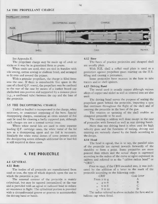
143.4 THE PROPELLANT CHARGE
SHELL CASE. PRIMER.
See Appendix E.The propellant charge may be made up of cords or
sticks or it may be in granulated form as grains.When cords are used, they are tied in bundles with
silk sewing, cotton sewing or shalloon braid, and arranged to fit over and around the primer.
With a granular propellant, the charge is filled loose into the case. I f there is consideiable free space in the case o f a fixed Q.F. round, the propellant may be confined to the rear of the case by means of a leather board cap shellacked into position and supported by a distance piece (e.g., a cardboard tube) between the cap and the base of the projectile.
3.5 THE DECOPPERING CHARGETinfoil or leadfoil is incorporated in the charge, when
necessary, to counteract coppering o f the bore. Special decoppering charges, containing an extra amount of foil may be used for cleaning a badly coppered gun, although such charges are not a normal service issue.
Where white metal lids are used to close separate loading Q.F. cartridge cases, the white metal of the lid acts as a decoppering agent and no foil is necessary. Similarly the white metal domes of some primers assist the decoppering action although additional tin or lead foil is still required in these cases.
4. TH E PROJECTILE
4.1 GENERAL4.11 Body
The bodies o f all projectile are manufactured from steel or iron, the type o f which depends upon the use to which the projectile is put.
The external contour of the projectile is mainly cylindrical, but may be tapered (streamlined) at the rear and is provided with an ogival or radiused head to reduce air resistance in flight. The cylindrical portion is provided with a circumferential groove or grooves to accommodate the driving band or bands.
4.12 BaseThe bases o f practice projectiles and shrapnel shell
are usually plain.With H.E. shell a rolled steel plate is used as a
protection against propellant gases reacting on the H.E. filling and causing a premature.
Some projectiles have recesses in the base to take tracers and/or shell igniters.
4.13 Driving BandThe metal used is usually copper although various
alloys of copper and nickel as well as sintered iron are also used.
The driving band serves the purpose of sealing the propellant gases behind the projectile, imparting a spin that continues throughout the flight o f the shell and o f centring the projectile in the bore of the gun.
The rotation or spinning of the shell enables an elongated projectile to be used.
The centring is seldom well done except in the case of projectiles with forward as well as rear driving bands.
More than one driving band is often used for high velocity guns and the functions of sealing, driving and centring are variously shared by the bands according to the design.
4.14 HeadThe head is ogival, that is to say, the parallel sides
o f the projectile are curved inwards forwardly of the shoulder to form a point. Some projectiles are more pointed than others and the actual shape is expressed according to the radius of the curve or ogive expressed in calibres and referred to as the “ calibre radius head” or “ C R H ” .
Prior to 1945, if the CRH exceeded two, it was indicated by the addition of a letter to the mark o f the projectile according to the following code:
C R H Code letterFrom 2 to 4 A
„ 4 to 6 B„ 6 to 8 . . C„ 8 to 10 D
The radius referred to above includes the fuze and/orballistic cap when fitted.
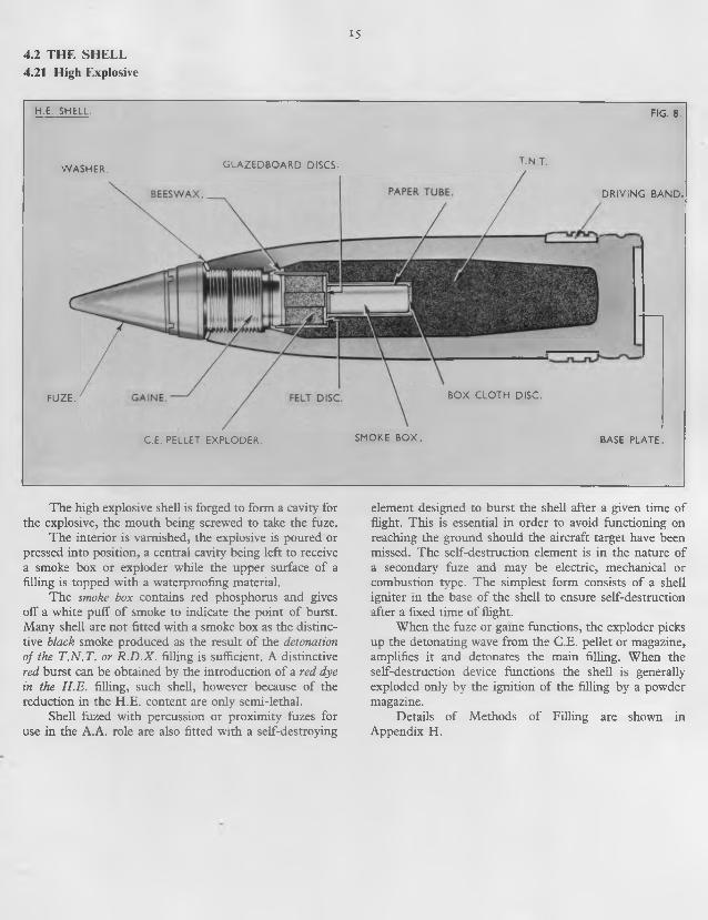
4.2 THE SHELL4.21 High Explosive
15
H.E. SHELL. FIG. 8.
FUZE.
WASHER. GIAZEDBOARD DISCS. T.N.T.
DRIVING BAND.
BOX CLOTH DISC.
C.E. PELLET EXPLODER. SMOKE BOX. BASE PLATE.
The high explosive shell is forged to form a cavity for the explosive, the mouth being screwed to take the fuze.
The interior is varnished, the explosive is poured or pressed into position, a central cavity being left to receive a smoke box or exploder while the upper surface o f a filling is topped with a waterproofing material.
The smoke box contains red phosphorus and gives off a white puff o f smoke to indicate the point of burst. Many shell are not fitted with a smoke box as the distinctive black smoke produced as the result of the detonation o f the T .N .T . or R .D .X . filling is sufficient. A distinctive red burst can be obtained by the introduction of a red dye in the H .E. filling, such shell, however because of the reduction in the H.E. content are only semi-lethal.
Shell fuzed with percussion or proximity fuzes for use in the A.A. role are also fitted with a self-destroying
element designed to burst the shell after a given time of flight. This is essential in order to avoid functioning on reaching the ground should the aircraft target have been missed. The self-destruction element is in the nature o f a secondary fuze and may be electric, mechanical or combustion type. The simplest form consists o f a shell igniter in the base of the shell to ensure self-destruction after a fixed time of flight.
When the fuze or game functions, the exploder picks up the detonating wave from the C.E. pellet or magazine, amplifies it and detonates the main filling. When the self-destruction device functions the shell is generally exploded only by the ignition of the filling by a powder magazine.
Details o f Methods o f Filling are shown in Appendix H.

i6
4.22 Shrapnel
SHRAPNEL SHELL. FIG. 9.
SOCKET. CENTRAL TUBE. BURSTING CHARGE.
DRIVING BAND.
Shrapnel shell have a separate head attached by a short screw thread or by set screws and twisting pins and an internal fillet o f solder. A recess in the base is fitted with a tin cup charged with gunpowder, and above this a thick steel disc with a central hole rests on a ledge. A central tube connects the fuze hole bush with the tin cup. The space between the central tube and the inside wall of the shell is filled with lead alloy bullets embedded in resin. The fuze hole bush is threaded to receive the fuze and screws into the nose o f the shell and is soldered to the tube.
The explosion o f the fuze sends a flame down the
tube to ignite the gunpowder charge which explodes. The steel disc is forced forward, carrying the bullets, resin, central tube, head of shell, with fuze hole bush and fuze, clear of the shell body. The components are thus separated and follow generally the path of the trajectory. The bullets, acting under centrifugal force, spread out to form a cone. The shell body is not broken up by the explosion.
A.A. shrapnel is fitted with a time fuze, but if this fails to burst in the air there is little risk o f the shell bursting on graze.
Shrapnel is not at present in use in the British service.
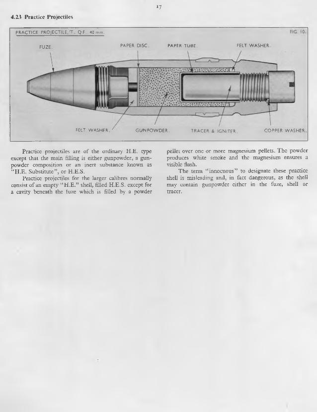
i74.23 Practice Projectiles
PRACTICE PROJECTILE, T „ Q.F 40 mm.
FUZE. PAPER DISC. PAPER TUBE. FELT WASHER
FELT WASHER. GUNPOWDER. TRACER & IGNITER. COPPER WASHER.
Practice projectiles are of the ordinary H.E. type except that the main filling is either gunpowder, a gunpowder composition or an inert substance known as “ H.E. Substitute” , or H.E.S.
Practice projectiles for the larger calibres normally consist of an empty “ H .E.” shell, filled H .E.S. except for a cavity beneath the fuze which is filled by a powder
pellet over one or more magnesium pellets. The powder produces white smoke and the magnesium ensures a visible flash.
The term “ innocuous” to designate these practice shell is misleading and, in fact dangerous, as the shell may contain gunpowder either in the fuze, shell or tracer.
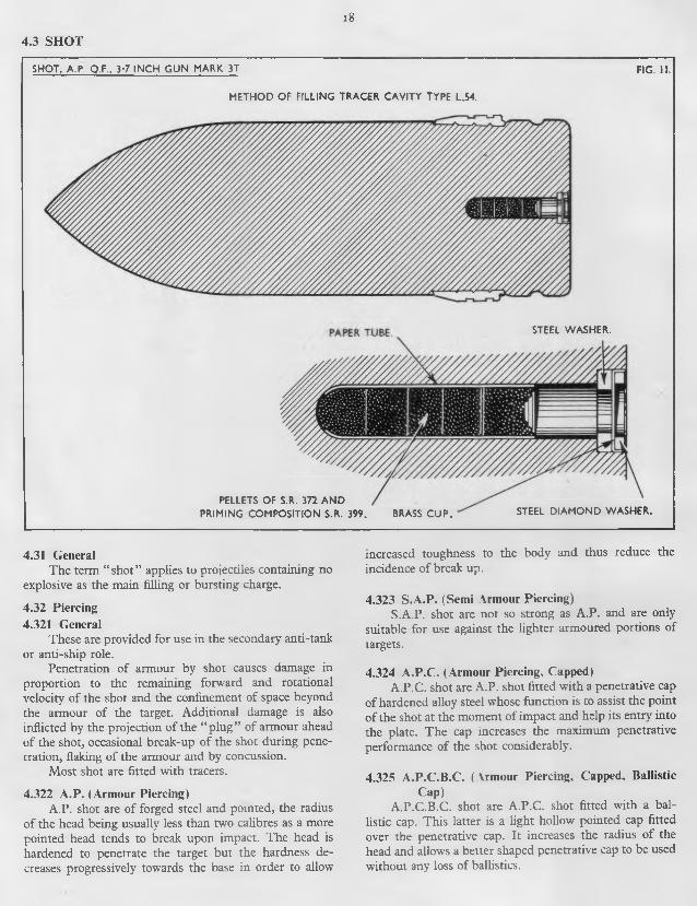
i8
4.3 SHOT
SHOT, A.P. Q.F., 3-7 INCH GUN MARK 3T
METHOD OF FILLING TRACER CAVITY TYPE L.54.
FIG, II.
STEEL DIAMOND WASHER.
STEEL WASHER.
PELLETS OF S.R. 372 AND PRIMING COMPOSITION S.R. 399. BRASS CUP.
4.31 GeneralThe term “ shot” applies to projectiles containing no
explosive as the main filling or bursting charge.
4.32 Piercing4.321 General
These are provided for use in the secondary anti-tank or anti-ship role.
Penetration of armour by shot causes damage in proportion to the remaining forward and rotational velocity o f the shot and the confinement of space beyond the armour o f the target. Additional damage is also inflicted by the projection of the “ plug” of armour ahead of the shot, occasional break-up o f the shot during penetration, flaking of the armour and by concussion.
Most shot are fitted with tracers.
4.322 A.P. (Armour Piercing)A.P. shot are of forged steel and pointed, the radius
of the head being usually less than two calibres as a more pointed head tends to break upon impact. The head is hardened to penetrate the target but the hardness decreases progressively towards the base in order to allow
increased toughness to the body and thus reduce the incidence o f break up.
4.323 S.A.P. (Semi Armour Piercing)S.A.P. shot are not so strong as A.P. and are only
suitable for use against the lighter armoured portions of targets.
4.324 A.P.C. (Armour Piercing, Capped)A.P.C. shot are A.P. shot fitted with a penetrative cap
o f hardened alloy steel whose function is to assist the point o f the shot at the moment of impact and help its entry into the plate. The cap increases the maximum penetrative performance of the shot considerably.
4.325 A.P.C.B.C. (Armour Piercing, Capped, BallisticCap)
A.P.C.B.C. shot are A.P.C. shot fitted with a ballistic cap. This latter is a light hollow pointed cap fitted over the penetrative cap. It increases the radius o f the head and allows a better shaped penetrative cap to be used without any loss of ballistics.

19
4.33 PracticeThis is similar to S.A.P. shot but of a lower grade
steel.
Powder pellets are sometimes perforated, in which case they serve to reinforce flash, or they may be solid and in this form constitute a delay.
4.34 ProofThis consists of a solid cylinder o f steel, fitted with
the standard driving band. It is used for proof of guns and mountings and is designed to withstand the high chamber pressures used at gun proof.
4.35 PaperThis usually consists of two or more portions. They
are made of paper cyfinders, closed at the ends with strawboard discs and filled with diamond grit or iron filings. The rear portion has a “ driving band” , or stop, also of board, formed at the rear.
Paper shot are used at proof of mountings to simulate firing stresses.
5. FUZES, GAINES, TRACERS AND IGNITERS
5.1 G EN ER A L5.11 General
Fuzes, gaines, tracers and igniters are conveniently considered together as the components o f the projectile that between them ensure the initiation of the bursting charge at the desired time and place, and, in the case of tracers, provide a visible indication of the trajectory.
5.12 Explosive Devices5.121 General
Explosives forming the explosive train of the various components o f the projectile are generally contained in either a detonator shell, magazine chamber, channel or bag.
The explosive may be loose, pressed in situ, or in the form of pellets. In this latter form a separate container is not always necessary.
5.122 PelletsThese are formed o f pre-pressed explosive, both
C.E. and powder pellets being used.
DETONATORDETONATING COMPOSITION.
FIG 12
LEADAZIDE
BRASS DISC. BRASS WASHE
BRASS DISC. BRASS WASHER. DETONATING COMPOSITION
5.123 Detonators and CapsThese are either igniferous or disruptive according to
whether they are required to ignite powder or detonate C.E. respectively.
Small igniferous detonators are also termed “ Caps” .Detonators and caps consist of small copper cups
containing the explosive, closed by a thin metal disc and a brass washer secured by turning over the lip of the cup.
Initiation is by impact with a needle, striker or anvil, or by passing an electric current through a filament in contact with the explosive.
5.124 MagazineThis can be formed either in the body of the fuze,
game, primer, etc., or can be a separate container secured to the body.
It may be either igniferous or detonating according to whether it is filled with powder to produce a flash or with C.E. to detonate an H.E. charge respectively.
5.125 ChannelsThese connecting finks may contain loose powder,
compressed powder, pellets o f powder or C.E., or may be empty and merely serve the purpose o f flash direction.
Channels filled C.E. or similar high explosive are used to ensure substantial continuity o f the detonating train.
MAGAZINE. FIG 13.
POWDER PELLETS.
MAGAZINE RING.
PO W DER- BASE PLUG.
SHUTTER.
MAGAZINE.
STEMMED C.E.
C.E, PELLET. BOTTOM CAP.

205.13 Mechanical Devices5.131 General
The ultimate object o f the mechanical devices is to ensure that the detonator is struck at the desired instant.
Premature action is prevented by various forms of holding and locking devices, and as a further safety measure, masking devices can be incorporated to block the detonating train to an H.E. bursting charge.
A component is said to be “ armed” when it is in such a condition that there is nothing to prevent initiation of the bursting charge, either on a disturbance o f the existing state of motion or rest (e.g., impact of a percussion fuze or movement of a blind) or on the functioning (normally or prematurely) o f a time or proximity device.
Although freedom from premature action is essential for both safety and operational reasons and embraces handling, loading and projection until well clear of the muzzle, the projectile must be fully armed on approaching the target.
The various devices in use will be described according to their principle functions of holding, masking and firing, after considering the forces used to operate them.
5.132 Forces5.1321 General
All components of fuzes, games, tracers, etc., are either fixed relatively to the projectile or are free to move within certain limits. The movement of the free components, controlled or restrained as necessary by friction and/or springs, depends principally upon the forces arising from acceleration, deceleration and spin, although it is also affected by “ side-slap” to an extent depending mainly upon the state of wear of the gun.
Some or all o f these forces are utilized to ensure correct operation as well as in various safety devices.
5.1322 Acceleration and DecelerationThe acceleration o f the projectile and fixed compo
nents tends to leave the free components behind. I f the acceleration is moderate, the loose parts “ creep back” , and i f violent, “ set back” . Conversely, deceleration causes “ creep forward” and “ set forward” .
Violent acceleration occurs at the instant of firing the gun, and comparatively moderate acceleration with the subsequent forcing of the projectile up the bore of the gun.
Moderate deceleration continues from the moment the projectile leaves the muzzle until it becomes violent on impact. Violent and momentary' deceleration also occurs with a worn Q.F. gun with appreciable free run-up when the driving band first takes up the rifling.
5.1323 SpinCentrifugal force, resulting from the rotation of the
shell, acts in a plane at right angles to the line of flight to force the free components outwards from the centre of the shell.
Centrifugal force is not normally intended to be effective until the shell has left the bore o f the gun as the free components are expected to be held in their original positions by frictional forces proportional to the set back forces in the gun.
5.1324 Side-SlapForces acting in a plane roughly at right angles to the
axis of the bore are also set up owing to inadequate centring o f the projectile. This causes the shoulder o f the projectile to hit against the bore of the gun. These forces, however, are only appreciable with a well worn gun, and in this case, the excessive hammering is known as “ side- slap” .
5.133 Firing Devices5.1331 Striker, Firing Pin or Needle and Anvil
A striker, firing pin or needle is a rod o f metal with a pointed end to impinge on the detonator. The American term “ firing pin” is synonymous with “ striker” and the distinction between a striker and needle is that o f size only, the needle being smaller.
An anvil is a steel block with a nipple projecting from the centre.
Initiation of a detonator is by impact with a striker or anvil nipple. The striker may be forced on to the detonator (Fig. 19) or the detonator (in a weighted holder or “ pellet” ) on to a striker (Fig. 14) or anvil (Fig. 32).
Striker and detonator are kept apart by a holding device. Additional and interlocking holding devices can also be incorporated.
5.1332 HammerSee Fig. 15.This is usually a rod with an enlarged head and is
mounted in front of the striker and used to “ hammer” the striker on to the detonator.
The hammer is often used with very sensitive fuzes designed to function on aircraft fabric or skin.
The sensitivity of the fuze can be reduced by having a thin diaphragm formed in the fuze head above the hammer. The shape o f the hammer head and thickness of the diaphragm is somewhat critical. I f such a fuze is too sensitive it may function on impact with raindrops.
In some cases, the hammer and striker are combined in one piece and the combined hammer and striker is then termed a “ hammer” .
5.1333 Striker SpringSee Fig. 2 1.The striker spring consists of a spiral spring sur
rounding the striker and used to drive the striker down on to the detonator when released by a trigger. This spring is kept in compression until released and must not be confused with the striker spring used as a holding device (see para. 5.1342).
21
FUZE No. 199 (ACTION ON SHOCK OF DISCHARGE) FIG. 14.
MECHANISM HOLE PLUG.
DETONATOR HOLDER.
D ETO N ATO R .
FLASH CHANNELS.
SPRING.
NEEDLE.
NORMAL. L ON FIRING.
5.1334 PelletThis is a metal weight, usually cylindrical in shape
and can be used to house a detonator and carry it on to a striker or anvil (e.g. the detonator holder in Fuze No. 199, Fig. 14).
5.134 Holding Devices5.1341 Shear Wire
This simple device consists of a short length of wire inserted in radial holes in register in two concentric sleeves. I f sufficient force is available the wire will be sheared and the sleeves freed.
5.1342 Striker Spring and Spring DiscThe striker spring consists of a spiral spring sur
rounding the striker to keep the striker separated from the detonator until overcome by a superior force (e.g., impact with the target).
The same function is performed by a corrugated spring disc in the centre of which is fixed a needle.
NEEDLE.DURING FLIGHT.
ARMING SLEEVE, CENTRIFUGAL BALLS AND FERRULE HAMMERHEAD
FERRULESTIRRUPSPRINGARMINGSPRING
FIG. 15
5.1343 Centrifugal Balls. Segments, etc., and ArmingSleeves
This combination depends for operation on two forces operating at right angles.
A number of balls, segments, etc., are retained under a flange of the striker by an arming sleeve. Movement of the arming sleeve due to, say, creep forward, uncovers the balls, etc., which are then free to fly out under centrifugal force to free the striker.
5.1344 Stirrup SpringThis consists o f a thin metal cylinder with lugs
turned over at each end and in opposite directions. The lugs can be used to lock two concentric sleeves together and rest at opposite ends o f each sleeve. One of the sleeves is fixed and the other kept against a lug by a spring. The lugs are designed to be straightened out by one of the forces described (para. 5.132) and thus allow the moving sleeve to be freed under action of the spring.
5.1345 FerruleThis is simply a sleeve or collar and is usually used to
denote the outer or holding sleeve used in conjunction with a stirrup spring to hold the moving (e.g., arming) sleeve.
5.1346 DetentThis is a form of latch, consisting of a small metal
cylinder or block working in a hole usually in the fuze body and covering a spiral spring under compression. The spring is used to keep the detent in a hole in a moving component and thus lock it. The detent spring may be designed to be overcome by any of the forces described (para. 5.132) to withdraw the detent and thus unlock the moving part.
A second hole can be arranged in the moving part so as to lock it in an alternative position.
c
22
5.135 Masking Devices or Shutters
SHUTTER FIG 16
SHUTTER
LOCKING WEIGHT.
SHUTTER OPEN. SHUTTER CLOSED.
DETENT.
These consist essentially of sliding or rotating blocks o f metal, which, in the shut or safe position block the channel leading to the magazine to provide safety from premature firing. In some cases the shutter consists of a number o f sliding leaves.
In the open or armed position, the detonator is connected to the magazine by channels in the shutter. In some cases, the striker and detonator are above the shutter and the shutter channels filled with C.E. In other cases, the striker only is above the shutter, the detonator being housed in the shutter and therefore only under the striker
♦ in the armed position.Shutters are kept in the closed position by a spring,
either operating directly or through an interlocking device.
The shutter opens under centrifugal force. During the passage of the shell up the bore o f the gun, centrifugal force has also to overcome friction between the shutter and fuze body due to set-back o f the former, and, under ideal conditions, this may be sufficient to prevent the shutter opening until the shell leaves the muzzle.
5.136 AssembliesExamples o f typical assemblies o f strikers, detonators
and associated holding devices with current nomenclatures are given on the next page. They are classified according to the force used to operate the striker and examples are given of components embodying particular assemblies.

23
Force Striker Detonator H olding D evice Com ponent
S et back on firing the gun
Fixed N eedle fixed to N eedle Pellet
M oving Detonator in Detonator H older
Sp ring between N eedle Pellet and detonator holder
Fuzes199223
Fixed Needle M oving Detonator in Pellet
Stirrup Spring Fuze80/44
Fixed N eedle Plug M oving Detonator attached to Pellet
Stirrup Spring
Fixed A n vil M oving C ap in Cap H older
Stirrup Spring T & I12
Action o f striker Spring
M oving Striker. (Collar at top o f striker to retain striker spring. Cam at base to rest on P illa r and Centrifugal S a fety Catch)
Fixed Detonator Cam o f striker rests on pillar and centrifugal safety catch. Rotation o f striker cam off pillar prevented b y Striker Lever being locked by H and Centre
Fuzes206207208 2 1 1
M oving Striker. (Collar near centre o f striker. T o p of collar retains Striker Spring and bottom rests on Safety Plate)
Fixed Detonator Collar o f striker rests on one toe o f centrifugal safety plate, the other toe being held by slot in centrifugal Firin g Arm . Rotation o f firing arm to free safety plate prevented by engagem ent w ith both Timing Disc and Set B ack Pin
Fuze2 14
/
M oving Striker. (T op o f striker slotted to admit toe o f Striker Bolt)
F ixed Detonator Slot in striker engaged by one toe o f striker bolt. Striker B o lt Spring rotates bolt to free striker as soon as a second toe o f bolt can slip into slot in Bottom Crown on rotation o f latter
Fuze209
Explosion o f fuze m agazine
M oving Needle. (U pper part flanged for Disc)
Detonator fixed to centrifugal shutter
Needle held in corrugated spring disc
G aine N o. 8
D irect Im pact w ith target
M oving Striker. (T op o f striker bored for Shearing W ire and bottom reduced in diam eter for Centrifugal H alf-C ollars)
Fixed Detonator Striker secured by shearing wire and locked by centrifugal half-collars, latter retained by Arm ing R ing and Ferrule
Fuze37 °
Striker m oving in Guide Bush. Striker Spring between striker head and top o f guide bush. Arming Sleeve and Arming Spring between bottom of guide bush and fuze body
Detonator fixed in centrifugal shutter
Striker kept o ff detonator by striker spring and locked by segments, the latter retained by arm ing sleeve and spring
Fuzes1 1 7230
Direct Im pact with target via Hammer
M oving Hammer and N eedle (upper end o f needle flanged to accommodate centrifugal balls)
F ix ed Detonator/
H am m er and needle retained B alls kept in holes in Striker G uide by Arm ing Sleeve and Stirrup Spring retaining the arm ing sleeve
Fuzes2232502 51255
S e t Forw ard on im pact w ith target
Fixed Needle M oving Inertia Pellet containing Detonator
Detent operated by setback and holding Centrifugal B olt in inertia pellet, latter also heldby Creep Spring
FuzesS ° i502
24
5.2 FUZES5.21 General
The fuze, in conjunction with the explodering system, ensures the correct functioning of the bursting charge, either after a set time (Time), on nearing the target (Proximity) or on impact with the target (Percussion).
Although particular types of fuzes are considered separately, one or more types may be combined into a single fuze (e.g., Time and Percussion).
Fuzes are normally placed either in the nose or base o f the shell.
With nose fuzes, the fuze body is shaped externally to conform to the shell contour and with base fuzes the body is cylindrical for entry into the shell cavity.
All fuzes (with associated gaines, if igniferous), embody devices to ensure:
Safety in handling, both before and during loading.
Bore and muzzle safety immediately after firing.Arming after leaving the muzzle.Firing of magazine and initiation of bursting
charge.The above devices are housed in the fuze body and
have been described in detail (paras 5 .12 and 5.13).For time fuzes, the fuze body also contains the time
element, and for proximity fuzes, the proximity element.
5.22 Time Fuzes5.221 General
Time fuzes are set for time before loading by rotation of a moving portion of the fuze against the fixed fuze body by means of a fuze key or fuze setting machine. Graduations are provided to enable the setting to be checked.
The time element may be either of the combustion or mechanical type.
The bottom portion of the fuze body generally forms a platform upon which the moving part rotates for setting the time of functioning. With British fuzes, the fixed part is either graduated in arbitrary fuze lengths for reading against an indicator on the moving part, or else the moving portion is made to operate a fuze length indicator on the fixed part. In addition, both fixed and moving parts generally have slots for the engagement by the pawls of fuze keys or the older fuze setting machines. Such slots are not required by the latest fuze setting machines which grip the fuze by means of knife rings.
The moving portion must be tight enough to prevent movement in handling, transport, loading and firing, and yet sufficiently loose to permit setting by the fuze key or fuze setting machine. The maintenance of the correct stiffness or tension is important.
5.222 CombustionThese fuzes embody a train of compressed powder
which burns through until the time as set has expired. The flash then fires a magazine.
The powder is generally contained in circumferential grooves in adjacent time rings, the powder burning in one ring until it can ignite the powder in the other, depending upon the relative position o f the two rings as determined by the setting.
Two rings are usually employed, the upper ring being fixed by pinning to the stem of the fuze body, and the other movable, or “ free” to rotate on the stem. The under surface of both rings is grooved for almost the entire circumference, the grooves being charged with fuze powder under compression.
The upper ring has a radial channel from one end of the powder groove to pick up the flash from the detonator, the channel containing a perforated powder pellet to facilitate this function. A second channel to the outside of the ring forms a gas escape, being fitted with a small closing disc to provide a watertight cover, and a perforated powder pellet to blow the disc clear when ignited.
The lower ring differs only in having a vertical channel (instead of a radial channel) to pick up the flame from the powder grooves in the upper ring.
25
FUZE No. 199. FIG. 18
COVER CAP.
NEEDLE.
WOOD RING.
-BASE PLUG.
PLUG SPRING.
DETONATORPIN.
TOP RING. BOTTOM RING
BODY.
MAGAZINE.
The central stem or body contains the detonator, needle and magazine.
Cloth washers are placed below the two rings to ensure a tight joint.
Both rings are secured by a cap which is screwed on to the stem o f the fuze and bears down on to the rings to secure the necessary tension.
5.223 Mechanical5.2231 General
These fuzes depend for their action on a clockwork mechanism consisting of a train of wheels, driven either by a spring or by centrifugal weights, and controlled by an escapement.
At the end of the time as set, the mechanism releases a lever which allows a striker to be driven on to a detonator to fire a magazine.
The following are typical mechanisms:
Type Drive Fuzes
Thiel Spring wound up during manu- 206, 207,(German) facture 208, 2 11
Junghans Spring assisted centrifugal 214(German) weights
Tavaro Spring partially wound up by 209(Swiss) fuze setting
The interior of the fuze body is usually bored out from both top and bottom to leave a diaphragm, the upper boring accommodating the “ clock” and the bottom forming a magazine and containing the detonator.
The Thiel and Junghans clocks are secured to the diaphragm by screws inserted from underneath and enclosed by a dome which is in turn retained by a screwed collar or sleeve which engages the interior threads o f the body. The dome is covered by a ballistic cap, or both dome and cap may be combined. The bottom of the dome is flanged, and between this flange and the bottom of the sleeve is a wire tensioning ring. The tension is varied by adjustment of the sleeve and the fuze set by rotation o f the dome.
The Tavaro clock is enclosed in a cylinder secured to the inside of the body. The top of the cylinder has four saw cuts to enable the cylinder to grip the top of the clock frame, and this device, combined with the pressure o f the moving cap on the securing washer above the cylinder and clock frame, provides the tension. The top of the clock is covered by a fixed cap secured to the body, and above this is the moving cap for fuze setting.
The clock of a fuze is very similar to an alarm clock* and will be considered in detail under the headings of Frame, Drive, Gear Train, Escapement and Timing.
5.2232 FrameThis consists of an assembly of flat plates, one above
the other, secured by bolts, dowels and distance pieces. The plates form platforms upon which are mounted the various components and in which holes are drilled as bearings for the shafts or arbors of the various wheels.
The plates are identified either by being numbered “ outwards” from the drive, or from the bottom, or by being described as “ bottom” , “ train” , “ panel” , “ top” , etc.
5.2233 Drive5.22331 General
The drive may be either spring, centrifugal or a combination o f both.
5.22332 SpringA mainspring consisting of a coiled steel spring is
housed in a “ barrel” or flat round box, and mounted on an arbor.
The outer end o f the spring is secured to the barrel and the inner end to the centre or barrel arbor.
With the Thiel clock, the spring is wound up during manufacture by rotation o f the barrel by a winding key engaging teeth on the periphery of the barrel.
With the Tavaro mechanism the spring is further wound by rotation o f the barrel arbor when setting the fuze.
26
FUZE 208
MUZZLE SAFETY BRIDGE
DOME""^LOCKING WEIGHT- SCREWED COLLAR SHEARING PIN. -—LOCKING PIN.— TENSIONING RING
T R IG G E R " 'CENTRIFUGAL SAFETY CATCH
H AN D ."' -LEVERSTRIKER:--------SHUTTER SPRINGSSHUTTER—---------BODY:----------------SECURING RINGMAGAZINE:-------C.E. PELLET.-----BOTTOM CAP.— CENTRIFUGAL SAFETY CATCH
DETONATOR DETONATOR HOLDER SHUTTER.
STEMMED C.E
MAGAZINE C E. PELLET.
SHUTTER
27
CENTRIFUGAL SAFETY CATCHFUZE SET VERY SHORT FUZE DETONATING
FUZES NO 207 & 208 CLOCKWORK MECHANISMS OF TINE FUZES. FIG. 20.
• FUZE NO. 214
FUZE AT SAFE
HAND RACEFRICTION DRIVEN ONLY
KEYED TO CENTRE ARBOR
OF SAFETY DISC
FIRING ARM
TENSIONING NUT
HAND SPRING TIMING DISC SPRING
CENTRE ARBOR
MAIN SPRING BARREL
MAIN SPRINGSAFETY LEVER
CLICK AXIS
CLICK SPRINGCENTRE WHEEL ^ i^ S P R IN G
ARBOR WHEEL4th PINION 4th WHEEL
HAMMER SPRING SETTING PIN COLLAR TIMING DISC TIMING DISC LUG
No. 5 PINION
GEAR SEGMENTS SET BACK PIN
AND SPRINGPALLET
SAFETY PLATE
STRIKER AND SPRING
DETONATORHOLDER
tc m i§ 3 t $
MUZZLE SAFETY DEVICE BRIDGE (208 FUZE
TRIGGER
HAND
LEVER
STRIKER SPRING
3rd PINION
3rd WHEEL-
FUZE NO 209
SPRING FOR STRIKER BOtT
BOTTOMSTRIKER BOLT
'-CENTRIFUGAL BOLT
BOTTOM CROWN WHEEL
PINION FOR BOTTOM CROWN WHEEL
STRIKER SPRING
STRIKER
MAIN SPRING
PALLET ARM AXLE-
WEIGHT HAIR SPRING
FERRULE
FIRST INTERMEDIATE WHEEL
TOP CROWN
PIN FOR STRIKER BOLT SPRING
BARREL ARBOR
5.22333 CentrifugalWith the Junghans clock, a pair of toothed quadrants
or gear segments with integral weights near one end of the teeth, are mounted eccentrically on either side of and in mesh with a central pinion. The gear segments are assembled with the weighted ends towards the centre of the fuze. A small coiled spring is also mounted on each arbor of the gear segments to assist in starting the clock.
On rotation of the shell, the weights are forced outwards by centrifugal force, and assisted by the springs, rotate the gear segments and thus the central pinion.
5.2234 Gear TrainA sequence of gear wheels to give the required step up
ratio from the drive to the escapement forms the gear train.
The larger wheels are termed gear wheels (or just wheels) and the smaller ones pinions.
Pairs of wheels and pinions are generally mounted together on the same arbor.
The ends of the arbor, usually reduced in diameter and coned, are termed pivots. Holes drilled in the plates form bearings for these pivots.
As with the plates, the wheels and pinions are identified either by being numbered or named according to their function.
28
5.2235 EscapementThis is the controlling mechanism by means of
which the power o f the drive is allowed to drip away— or escape—in a steady stream.
It comprises the escape wheel, pallet and hairspring.
5.22351 Escape WheelA wheel with specially shaped teeth for engagement
with the pallet pads (see below) and the final wheel in the gear train.
5.22352 Pallet or Balance ArmThis consists of a straight steel bar with widened or
weighted ends, termed the “ Pallet Arm ” , at the centre of which and at an angle to it, are two short arms with the ends turned up or down. These short arms are termed “ Pallet Pads” (or sometimes just “ pallets” ) and engage the teeth of the ’scape wheel one at a time.
The pallet is mounted on a Pallet Arbor.The pallet performs the same function as the balance
wheel of a watch.
5.22353 HairspringA thin spring, either held loosely between two fixed
supports or coiled with one end only fixed. The centre of a straight spring or the free end o f a coiled spring is connected to the pallet arbor.
5.22354 ActionVibration of the hairspring and pallet disengages one
of the pads from the ’scape wheel. In doing so, the pad receives an impulse or kick from the escape tooth as it
jumps forward before being momentarily locked by the entry of the other pallet pad into an adjacent tooth. This action is repeated by the disengagement of the second pad. The resulting series o f impulses is transmitted to the pallet arm and results in an oscillation which is maintained at a rate determined by the weight and length (or moment) o f the balance arm and the bending or torsional properties of the hairspring.
5.2236 TimingAs with an ordinary clock, the fuze mechanism must
be regulated for correct time keeping. This is affected by adjustment of the hairspring and is generally done before the mechanism is assembled into the fuze and before the fuze is “ filled” , i.e., before the explosive elements are assembled. Unlike an ordinary clock, however, the speed of running is affected by the rotation of the projectile. This “ spin effect” is determined for each type of mechanism and is allowed for when regulating.
With the clock correctly adjusted, the time taken for the fuze to function from the instant of firing the gun depends upon the arrangements made for starting the clock and for actuating the firing mechanism at the end of the time as set. In general terms, the time of running is set by the positioning o f a “plate”. This plate incorporates a “ slot” into which an “arm ” is designed to slip at the end of the time as set. Either the plate is rotated by the clock against a fixed arm, or vice versa.
This rotation is started by the firing of the gun and the slipping of the arm into the slot actuates the firing mechanism.
The sequence o f this action and the operation of the safety and other devices is shown in the following table:
29Instant Operation Detail
Before firing . Setting T h e time o f running is set on the fuze b y rotating the dome or cap to position an internal circular “ plate ” relative to the centre arbor
F irin g o f gun . Locking o f fuze setting Set-back or centrifugal action fixes the “ p la te ” in the position set
U nlocking o f clock Set-back or centrifugal action
Shell travelling up bore o f gun
Clock jam bed Friction on pivots and bearings due to set-back probably prevents clock starting
Shell leaves m uzzle of Shutter armed Detonator and magazine connected
Striker armed Centrifugal device w ithdrawn from striker
Clock freed Set-back ceases and the escapement starts. Centre arbor rotates either the “ p la te ” against the “ a rm ” or vice versa
Shell still near m uzzle o f gun
M uzzle Safety T h e “ a rm ” prevented from slipping into the “ s lo t” when the plate position corresponds to £ero setting by a m uzzle safety device
Expiration o f time as determ ined b y setting
Striker released to fire the detonator
T h e “ a rm ” slips into the “ s lo t” in the “ p la te ” to trigger the striker
FUZE No. 214. FIG. 22
CAP.
SCREWED COLLAR>
HAMMER SPRING CUP.
No 214 IL. WO. CO. 1943 (ENGRAVED ON BACK).
TENSIONING RING:
SETTING MARKS AT SAFE.
PLATES BODY.
STEMMED C.E SHUTTERt
SHUTTER SPRINGMAGAZINE SECURING
RING.MAGAZINE:
BOTTOM CAP.
LOCKINGSCREW.
DETONATOR.
H E. PELLET.

30
5.2237 Detailed Nomenclature and Functioning docks. The nomenclature and functioning o f these keyThe “ plate” , “ slot” and “ arm” referred to in the components in the three typical mechanisms is shown in
previous paragraph take various forms with different the following table:
M echanism T hiel J unghans Tavaro
Fuze 3 0 6 ,2 0 7 ,2 0 8 ,2 1 1 2 14 209
“ P la te ” H and Race. A race-way form ed as an integral part o f the dome
Timing Disc. Frictionally held to Centre Arbor. A bove this and screwed to the dome is a Hammer Spring and Setting P in , the latter engaging an upturned lug on the disc
Bottom Crown. G eared to Centre Arbor and to m oving Cap
“ S lo t ” . Silhouette o f hand cut in flat surface o f hand race
Sm all curved slot cut in from the periphery o f tim ing disc
Bevelled slot cut in rim o f bottom crown
“ A r m ” Hand. Slotted to the centre arbor and kept bearing on the undersurface o f the hand race b y the hand spring
Finger o f Firin g Arm Lever. K ept bearing on the periphery o f the tim ing disc b y centrifugal force acting on a weight on the other end o f the lever
“ Fo llo w er” toe o f S triker Bolt. K ep t bearing on the inside o f the rim o f the bottom crown by the striker bolt spring
Bore Safety D evice
M u zzle Sa fety B ridge. Covers the hand at short settings to prevent it entering slot
Sa fety Disc. Secured to the centre arbor w ith a projecting lea f to mask the slot at short settings
Centrifugal B olt. Has a raised and bevelled step which occupies slot in bottom crown at short settings and prevents entry o f toe o f striker bolt
5.2238 Detailed Sequence of ActionThe complete sequence of action o f the three typical fuze mechanisms is as follows:
Operation T h ie l Clock Junghans Clock T avaro Clock
Setting .
*
Hand race o f dome rotated against friction between dome and body as m aintained by pressure o f sleeve on tensioning ring. Hand held by lug o f trigger
Setting P in on dome rotates T im ing D isc on centre arbor against friction between disc and arbor and between dome and body as m aintained by pressure o f sleeve on tensioning ring. Centre arbor held by locking o f pallet arm b y safety lever and tim ing disc held by setting pin
Cap rotated against friction on securing washer between fixed cap and top o f clock fram e and between top o f cylinder and clock fram e. Rotation o f cap winds up m ainspring and turns bottom crown. A fter the crown has turned through about secs, o f setting, the bevelled edges o f centrifugal bolt and slot force the centrifugal bolt through the slot to ride on the outside o f the bottom crown
Locking o f Setting
Fuzes 206 and 207. Splined Locking R ing inside the dome sets back to shear the w ire rivets in the side and be impaled on Locking Pins in the body to lock the dome and thus the hand race
Fuzes 208 and 2 1 1 . A Locking Weight inside the dome and above the hand race sets back to shear the Shear Wires and drive Locking Pins into recesses in the body and thus lock the dome to the body
N o positive locking device. R eliance is placed on friction between tim ing disc and centre arbor after freeing o f tim ing disc from setting pin
Centrifugal Locking Levers engaged Toothed R ing inside fixed cap to lock the m oving cap and thus the bottom crown
U nlocking the clock
T h e Trigger sets back and releases the hand. T rig g er kept back by Trigger Locking Bolt
T h e tim ing disc is released from setting pin by the ham m er setting back and flattening the upturned lug o f the tim ing disc. T h e tim ing disc is now free to rotate with the centre arbor
No positive unlocking action at this stage
3i
Operation T h iel Clock Junghans Clock T avaro Clock
O pening of Shutter
Shutter swings open by centrifugal force and thus connects detonator and magazine. (Sim ilar action also occurs w ith the gaine shutter used with Fuzes 206 and 207)
Shutter swings open b y centrifugal force and thus connects detonator and magazine
T h e leaves o f the shutter open by centrifugal force to open the passage between striker and detonator. Should the striker be prem aturely released, the striker w ill lock the shutter leaves perm anently in the closed position
A rm ing o f Striker
Centrifugal Sa fety Catch swings out to w ithdraw toe o f catch from cam o f striker
Set B ack P in drops back and no longer prevents rotation o f firing arm
Freeing o f Clock
Escapem ent started by vibration o f shell and the centre arbor rotates the hand
T h e Sa fety L ever flies clear o f the end o f the pallet arm and in doing so distorts the hairspring and gives a flick to the pallet arm to start the escapement. T h e centre arbor turns the tim ing disc
T h e Stop Levers fly outwards and release the pallet arm and thus allow the centre arbor to rotate the bottom crown back towards the zero position
M uzzle Safety H and prevented from rising b y the M u zzle S a fety Bridge. (Fuzes 208 and 2 1 1 only) at settings below 0.57 (0.72 secs.)
A rm o f firing lever prevented from entering slot o f tim ing disc by projecting leaf o f safety disc at settings below 1 .3 2 (1.6 7 secs.)
“ F o llo w er” toe o f striker bolt prevented from entering slot in bottom crown b y step o f centrifugal bolt occupying slot at settings below 1.25 ( 1.2 5 secs.)
R unning of clock in flight
A fter rotating clear o f the muzzle safety bridge the hand bears on the under surface o f the hand race
Fin ger o f firing arm bears on the periphery o f the tim ing disc as it rotates
“ Follow er ” toe o f striker bolt bears on inner surface o f bottom crown as it turns. Centrifugal bolt kept clear o f the slot by centrifugal force
Release of striker
H and spring forces hand up through slot o f hand race to release the lever and allow the striker spring to rotate the striker cam o ff the pillar and force the striker down on to the detonator
Centrifugal force makes the finger o f the firing arm lever slip into slot o f tim ing disc to rotate the firing arm lever and allow the striker safety plate to swing clear o f the striker. T h e spring can then drive the striker down on to the detonator
Striker bolt spring makes the “ fo llow er” toe o f the striker bolt slip into slot in bottom crown to w ithdraw the other toe from slot in striker to allow striker to be driven down on to the detonator.
5.23 Proximity or Variable Time (V.T.) Fuzes
5.231 GeneralProximity or “ Variable Tim e” fuzes are operated by
the reflection o f wireless waves from the target. These waves are transmitted from the fuze and the reflected waves from the target interfere with the direct waves to give a beat which is utilized to trigger the firing mechanism of the fuze.
The distance from a standard size and nature of target at which these fuzes will operate is predetermined. The size and nature of the actual target being engaged affect its powers of reflection and impose small variations on this predetermined distance.
Safety devices are included as for other types of fuzes. These may be either electrical or mechanical.
A self-destruction device is included in fuzes for use in the A.A. role to prevent functioning of the fuze on nearing the ground should it not have been operated by the target.
5.232 ElementsThe V .T . fuze is essentially a self-contained battery
wireless transmitter and receiver with built-in aerial. It consists of an oscillator, amplifier and firing circuit and is used with a gaine or auxiliary detonator.
5.2321 AerialThis consists of either a plated steel cup embedded in
the plastic nose of the fuze or a half loop o f wire fixed over a former in the nose. The two types of fuzes are referred to as “ Capped” and “ Capless” respectively.
5.2322 BatteryThis is a reserve type of primary battery with the
electrolyte contained in a glass ampoule which is broken by set-back on firing the gun. It gives high tension supply for the plates and low tension for heating the filaments o f the valves and negative bias for the grid of the thyratron in the firing circuit.
32
BLOCK DIAGRAM OF V.T. FUZE. FIG. 23
5.2323 OscillatorThis is a combined transmitter and detector which
sends out waves o f radio frequency and receives them again after reflection from the target. The interaction of the two waves produces Ripple Impulses of audio frequency.
5.2324 AmplifierThis amplifies the signals from the oscillator and
passes them on to the firing circuit. Pentode valves are employed for A.A. fuzes to give high sensitivity. For fuzes for use in the ground role, triodes are used.
5.2325 Firing Circuit
This consists of a grid condenser, thyratron or gas filled triode valve, firing condenser and electric detonator, together with a spin switch and unshorter switch.
The grid of the thyratron is negatively biased and receives the amplified signals from the amplifier. The plate or output circuit is completed through the firing condenser in series with the detonator. The unshorter switch shunts the detonator and the spin switch shunts the whole of the output.
The grid and firing condensers are charged by the battery through resistances. When a strong enough signal is received on the grid, the bias is destroyed and the thyratron triggered, allowing plate current to flow and the firing condenser to discharge through the detonator and thus initiate the magazine.
5.23251 Unshorter SwitchThis consists o f a metal cup, the top of which is
fitted with a central insulated contact stud. The bottom of the cup is made porous. The cup is contained in a steel shell, the bottom of which forms a sump beneath the cup.
The cup is filled with mercury and the switch is mounted radially with the contact stud towards the centre of the fuze.
Before firing, the mercury keeps the switch closed and thus shorts the detonator. A few seconds after firing, centrifugal action forces the mercury into the sump to open or unshort the circuit and thus give Delayed Arming.
5.23252 Spin SwitchThis consists of a metal reed contact operated by
centrifugal force. The contact opens soon after firing and with A.A. fuzes it is also designed to close again when the spin has decreased in flight to a predetermined extent. Before firing, therefore, the switch provides safety in handling by discharging the firing condenser to earth should the battery be accidently activated.
In flight, i f the thyratron is not operated by a target signal, the eventual closing o f the switch again will give self-destruction by discharging the firing condenser, this time through the detonator, thus initiating it.
5.2326 Gaine or Auxiliary DetonatorThis consists o f a shutter assembly over a C.E.
magazine. Two shutters are mounted one above the ether, one displacing a disruptive detonator and the other a C.E. filled channel from the axis of the fuze.
5.233 Safety Devices5.2331 Before Firing
The battery is not activated until the gun fires.The spin switch is closed and shorts the firing con
denser.The unshorter switch shorts the electric detonator.The shutter prevents a flash from the electric deto
nator from initiating the magazine.
335.2332 After Firing
The unshorter switch provides delayed arming and muzzle safety.
The battery is not fully activated until about half a second after firing.
5.2333 In FlightThe spin switch gives self-destruction should the
fuze not be operated by the target.
externally at the top to enter the base ring. The interior has a left-hand thread to take a holding ring to support the battery and rear fitting and also to take the top of the gaine.
The front case contains the aerial and monitor and the sleeve houses the battery and rear fitting with the gaine screwed into the base.
Some types of fuze have a heavy coating of wax on the outside which should not be removed.
5.2334 Disposal of BlindsThe active life o f the battery is no more than about
two minutes.
V.T. FUZE ASSEMBLY.
OSCILLATOR
AMPLIFIER
BASE PLATE
RESERVEBATTERY
ACID AMPOULE-
REAR FITTING
HOLDING RING.
SHUTTERS
GAINE.
5.234 AssemblySub-assemblies of the components consist of the
monitor or bundle, reserve battery, rear fitting and gaine.The monitor comprises the oscillator, amplifier and
firing circuit except for the spin switch, unshorter switch and electric detonator embodied in the rear fitting. The gaine contains the shutter and magazine assembly.
The fuze body or container consists of a plastic front case moulded on to a metal base ring or threaded insert into which a sleeve or can is secured from underneath.
The base ring is threaded externally for screwing into the fuze hole of the shell and has two parallel slots for engagement by the keyfor inserting and removing the fuze.
The cylindrical steel sleeve is o f smaller diameter to enter the fuze hole o f the shell. It is screw-threaded
5.235 CharacteristicsFuzes are generally designed within fairly narrow
limits according to their particular role, and are often specific to particular guns.
Fuzes for use in the A.A. role have an arming time of about 1 1 seconds and the spin switch gives self- destruction. The time to self-destruction is predetermined and limits the minimum Q.E. below which the fuze should not be used when firing over friendly territory. These fuzes function within sixty feet of an aircraft target.
Fuzes for use in the ground role are less sensitive, have an arming time of over five seconds and the spin switch does not give self-destruction. These fuzes function at about fifty-five feet over dry land when fired in the lower register and at about ten feet in the upper register.

345.236 Service Fuzes
Fuzes now in the service were all made in the United States and the only British A.A. gun for which they are approved is the 3.7-inch Marks 1 to 3.
5.2361 NomenclatureAll fuzes carry the U .S. Navy designation of Mark 45.In the development stage, each type of fuze was given
a “ T ” number. This is followed by an “ E ” number to designate the model. A final letter may also be used to indicate a minor modification. This is the system used to describe these fuzes in the British service. An example of a complete nomenclature is:
T .149 E .iA
An alternative nomenclature has been adopted by theU .S. Army now that the fuze is a standard store. In this case, each type is given an “ M ” number followed by an “ A ” number to indicate the model. An oblique stroke, followed by a number may also be used to denote a minor modification.
e.g. T .149 E .iA becomes M.95 A .i /i
The three types of fuze approved for use with the 3.7-inch Marks 1 to 3 guns are described below.
5.2362 T.97 (M.98)This fuze is for use in the ground role only. It can be
distinguished from the A.A. fuzes by having a truncated nose.
5.2363 T.98 (M.94)This is the standard A.A. fuze with a contour modelled
on that of the British No. 208 mechanical time fuze.It has a mean time to self-destruction of about thirty
seconds and a minimum safe Q.E. of thirty degrees.
5.2364 T.149 (M.95)This varies from the T.98 fuze only in that the mean
time to self-destruction is about ten seconds and the minimum safe Q.E. is reduced to fifteen degrees.
5.24 Percussion Fuzes5.241 General
Percussion fuzes are of various types according to the speed of action required. Generally speaking, the Direct Action fuze has the fastest action, followed closely by the Graze fuze and finally by the Delay Action Graze fuze.
The essential elements of percussion fuzes are the firing mechanisms accompanied by the holding and safety devices. These have already been described in detail in para. 5 .1.
A self-destruction device is necessary for shell fitted with percussion fuzes when used in the A.A. role to prevent functioning of the fuze on impact with the ground should the target be missed. Such a device may be embodied in the fuze as a time element or be entirely separate as with a shell igniter (para 5.42).
FUZE, PERCUSSION, D A ., No 117 MARK 8. PLAN VIEW OF SHUTTER. -SAFETY CAP.
COVER.
STRIKERHEAD.
STRIKERSPRING.
SHUTTERLOCKINGWEIGHT
ARMING SLEEVE SEGMENTS.ARMING SPRING STRIKER SLEEVE. STRIKER.BODY.LOCKING WEIGHT SHUTTER. MAGAZINE BOTTOM CAP.C.E. PELLET. FIG. 27.
FUZE No. 255 MARK I .
SHUTTERPART n .
PAPER DISC
FERRULE
BODY.
HEAD
FERRULE
STIRRUP SPRING
STRIKER GUI DETONATOR
LEAD AZIDE DETONATOR
PELLET.
STEMMED C.E MAGAZINE,
HOUSING.
ARMING SLEEVE.
ARMING SPRING.
STRIKER.
DETONATOR PLUG.COMPOSITION.
PELLET SPRING,
HALF COLLAR.C.E,
SHUTTER, PART I.
STIRRUP SPRING .
LEAD WASHER. STEMMED PLUG.
C.E PELLET.
HAMMER. FIG. 28
5.242 Direct Action (D.A.) FuzesThese fuzes depend for their action on the driving
of a striker on to a detonator by direct action on impact with the target.
35
BASE FUZE. FIG. 29,
PEA BALL.
MAGAZINE COVER.
NEEDLE CAP.
- BODY.
DETENT.
UPPER CENTRIFUGAL BOLT
MASKING BOLT.
DETENT SPRING.
RETAINING BOLT.
DELAY FITTING.
PELLETS, (FLASH HOLE.)
PRESSURE PLATE.
LOWER CENTRIFUGAL BOLT.
INERTIA PELLET.
PELLET.(IGNITION CHAMBER.
MAGAZINE PELLET
C.E. PELLET.
CREEP SPRING
NEEDLE.
DETONATOR.
STEMMED C.E.
5.243 Graze FuzesThese fuzes depend for their action on a weighted
needle being driven on to an igniferous detonator (or vice versa) by setting forward on the sudden deceleration caused by impact with or grazing o f the target.
5.244 DelayDelay in fuzes may be fixed or optional and is attained
in two ways, which may be employed together.
One way is to interpose a baffle in a flash channel to force the flash td follow a tortuous path.
The other way is to interpose a layer o f solid pyrotechnic material which must be burnt through to allow the flash to proceed on its way.
Having regard to the characteristics o f detonation, it will be evident that delay can only be obtained in the igniferous train of a fuze and not in the disruptive train. Consequently a disruptive fuze can only have delay incorporated i f the early part o f the explosive train is igniferous.

36
GAINE No. I I , MARK 4 FIG. 30
SHUTTER CLOSED (W ITH HOLDER ETC REMOVED)
SHUTTER OPEN( WITH HOLDER ETC. REMOVED )
PAPER DISC
BODY
SHUTTER
PAPER DISC DETONATOR PLUG
DETONATOR
HOLDER
STEMMED C.E.
C.E. PELLET
BOTTOM CAP
5.3 GAINESA gaine is a device to transform the flame given off
by a powder magazine into the detonating wave required to detonate an H.E. filling.
It consists of a disruptive initiator and C.E. magazine and is generally contained in a metal body for screwing into the shell immediately below the fuze. The gaine may be designed to screw into the nose of the shell or may be embodied in the fuze itself.
The gaine often contains a shutter (para. 5.135) to provide bore and muzzle safety.
The American term “ Auxiliary Detonator” is synonymous with “ Gaine” .
5.4 TRACERS AND IGNITERS5.41 Tracer
See also Fig. 1 1 .This is a device to emit light (and usually smoke) to
form a trace for night and day observation of the path of the projectile.
It consists of a train of tracer composition usually topped with priming composition and/or gunpowder and
is contained either in a cylindrical metal body for placing at the base of the projectile or in a special cavity prepared in the base of the projectile.
The tracer, when contained in a tracer body, is referred to as “ Internal” or “ External” according to whether it is inserted flush with the base of the projectile or projects outside. A tracer inserted directly into a shell cavity is known as “ Cavity” .
37The time of burning depends on the quantity, com
position, compression and degree of confinement of the filling.
The tracer composition is ignited by the priming composition which latter is ignited either by the flash of the propellant or by a tracer igniter (para. 5.44). In the former case, the rear o f the tracer body is generally closed only by a thin disc o f metal or celluloid that is ruptured by the explosion of the propellant. In the latter case, the base of the igniter is covered by a closing disc and both igniter and disc are ejected after initiation by the pressure built up by the burning composition.
5.42 Igniter, ShellThis is a device to ensure the self-destruction of the
shell after a fixed time, should the bursting charge not have been initiated by the fuze.
The shell igniter is very similar to a tracer except for the addition of a charge of gunpowder contained in a small chamber in front of and connected with the composition cavity. The gunpowder chamber and connecting channel containing gunpowder pellets is known as the Relay and serves to give positive ignition o f the bursting charge.
As a visible trace is not necessary for a pure igniter, the igniter composition emits little or no light or smoke and for this reason the shell igniter is sometimes referred to as an “ invisible tracer” .
The burning through of the train of composition determines the time, and the subsequent ignition o f the gunpowder charge ensures the explosion o f the bursting charge in the shell. A shell filling thus ignited is unlikely to detonate.
5.43 Tracer and Igniter, ShellThis is a combination o f a traeer to give a visible
trace and a shell igniter to ensure self-destruction.In some cases the powder magazine or relay is re
placed by a self-destroying detonator inserted in front of the shell cavity containing the tracer composition. This self-destroying detonator consists of a disruptive detonator
and C.E. pellet so that in this case the shell would be destroyed by detonation rather than by explosion.
The “ Tracer and Igniter, Shell” is commonly referred to as a “ Tracer-Igniter” and can thus be confused with the “ Igniter, Tracer” or tracer igniter (para. 5.44 below).
5.44 Igniter, TracerSee Fig. 32.This is a device to ensure the ignition of the tracer
composition where this is not done by the propellant flash.
It consists o f a cylindrical metal body for insertion in the base o f the projectile and containing an anvil and an igniferous detonator, a cap holder held by a stirrup spring and operated by set-back and a connecting channel to some loose gunpowder above the priming composition in the main cavity.
The base o f the igniter is covered with a closing disc and both igniter and disc are ejected by the pressure built up by the tracer composition after ignition.
6. DRILL AMMUNITION6.1 GENERAL
Drill ammunition contains no explosive whatever and all items o f this ammunition are painted black with the word “ D R I L L ” in white lettering. (Any drill ammunition not so painted must be returned to R.A.O.C. and not used.)
Live ammunition, Practice as well as Operational, must not, in any circumstances, be used fo r drill purposes.
All preliminary training is carried out with drill ammunition and in peace-time no other sort o f ammunition should be on the gun position at the same time. In war, however, although drill ammunition is still used for training, operational ammunition may also be on the gun position. This introduces a risk o f error and accident which can only be avoided by very careful attention on the part of all concerned
The broad general rule to follow at operational positions or elsewhere when operational ammunition is present is to store the drill ammunition in some central place clear of the guns. It should be brought to the gun position for training only, all five ammunition being segregated and steps taken to ensure that the two types do not get mixed up during drill. On completion o f the training period, the drill ammunition should be returned to the central store, all items carefully checked and live ammunition excluded.
6.2 CARTRIDGES6.21 Fixed Ammunition
Drill cartridges to represent fixed ammunition are of three main types.
The earlier designs comprised a hardwood or vulcanized rubber body shaped to the contour of the complete service round and fitted with a brass nose and base
D

38to standard dimensions. With the smaller calibres, the brass nose represented the whole projectile. The nose and base were secured to each other by a central steel rod, the latter being surrounded by lead weights to bring the drill cartridge to the service weight. The nose could be either pointed or threaded to take a fuze, while to protect the point o f the striker, the base was either fitted with a rubber plug or recessed.
A later design makes use of the service cartridge case and empty shell. The shell is secured to the base by a central steel rod bolted to the base o f the cartridge case and shell respectively, the space between the rod and walls of the cartridge case being filled with hardwood slats. The driving bands of the shell are reduced in diameter and the cartridge case coned and indented to the shell as for service. A drill fuze can be fitted to the shell.
The latest design for Heavy A.A. also utilizes the service cartridge case and empty shell, but the central rod is replaced by a steel tube. The shell is bored out from the rear to the full diameter o f the standard cavity to take the steel tube which fills the cavity right up to the fuze hole. This method of construction gives much greater rigidity to the whole round. A special adapter fitted to the base o f the cartridge case, and another screwed into the fuze hole o f the shell, secure the ends o f the tube. The space between the tube and cartridge wall is filled with hardwood slats, the driving bands are turned down and the cartridge case coned and indented to the shell. A drill fuze can be fitted to the shell.
6.22 Separate Loading AmmunitionThere are two types of projectile. One is specially
made o f cast iron, bored out from the base to bring to the correct weight, and the cavity closed by a plug. The other type is a converted empty H.E. shell with the driving bands turned down.
The cartridge is similar to the latest type of fixed ammunition, a central steel tube connecting the base of the service cartridge case to a special brass fid, the space between the tube and walls o f the cartridge case being filled with hardwood slats.
6.3 F U Z E SThese may be made as drill fuzes or they may be
adapted from service fuzes by emptying or burning out the explosive elements.
As with other drill ammunition, all drill fuzes should be painted black with the word “ D R I L L ” in white lettering.
7. RECORDS7.1 AMMUNITION 7.11 Lots 7.111 General
Component parts of service ammunition are made up in lots, each lot being the product of one manufacturer under the same set of conditions and from the same raw material.
Each unit m the lot is assumed to be uniform with the remainder.
The number o f units forming a lot varies, and may range from iooo for primers, or 2000 for mechanical time fuzes, to 20,000 or more for small-calibre propellant charges.
A lot number is allocated to each lot and wherever possible each item is marked with the lot number to facilitate identification. -
The Inspector of Armaments maintains extensive technical records of all lots, also o f the complete rounds, and is in a position to investigate any defect arising later, and in most cases, trace its cause.
7.112 PropellantsPropellant charges deteriorate in store and the rate
of deterioration depends mainly on the storage temperature. Efforts are made to store all cartridges o f the same propellant lot number under similar conditions and careful records of the storage temperature are kept in peace and reported to the Inspector of Armaments. From these sources, and from the records o f periodical technical tests, the remaining “ fife” of the lot is determined. In war, periodic chemical tests are impracticable, while in mobile units the recording of storage temperatures cannot be done satisfactorily, so both requirements are suspended. This can be permitted with reasonable safety as most cartridges are made up with modern propellants which should not cause any anxiety as to stability for at least five years.
7.12 Batches 7.121 General
For ballistic and record purposes, fixed Q.F. ammunition is made up and issued under a batching system. With this system, Q.F. cartridges are divided into two categories.
Where combustion time fuzes are fitted the batch contains fuzes all o f the same lot and the cartridges are said to be “ batched on the fuze” . Where combustion time fuzes are not fitted, however, the batch contains propellant charges all o f the same lot and in this case the cartridges are said to be “ batched on the propellant” . Lots batched on the fuze generally contain 2,000 cartridges, whereas those batched on the propellant may comprise anything from 5,000 to 20,000 cartridges.
To simplify records and the ready location of components, batches are sub-divided into sub-batches on the basis of the next important item in the cartridge. Thus, cartridges batched on the fuze are sub-batched on the propellant, and those batched on the propellant are subbatched on the fuze, except for shotted cartridges, when sub-batcbing is on the primer or tracer.
Each batch is allocated a serial number and each subbatch is given a letter or numbers to follow the batch number.
To simplify records still further, batched ammunition is divided into types and a letter allocated to each is
39placed before the batch number. The letters used to indicate these types are as follows:
B Full Charge, H.E.C „ „ SmokeE „ „ A.P. and S.A.P. ShotF „ ,, Target ShellM Reduced Charge, H.E.S Full Charge, Practice Projectile (filled powder)T „ „ „ „ (filled inert)U Reduced Charge, Practice Projectile (filled powder)
The complete description therefore consists o f the type letter, batch number and sub-batch letter, e.g. B.2406A.
As there are more propellant charges in a lot than there are combustion time fuzes in a lot, it follows that the majority o f cartridges batched on the fuze will not require to be sub-batched and therefore the absence of any sub-batch letter need cause no comment.
The batching system and marking is designed to help the gunner, the store-holder and the central records. The main features to note are:
All propellant charges in a batch are ballistically equal.
Cartridges should be stored according to batches where these exist, and all ready-use rounds at a gun should be from the same batch or sub-batch.
7.122 V .T . FuzesThese are invariably batched and issued separately.Existing service fuzes which were manufactured in
the United States o f America are batched on the basis of a twenty-four-hour factory output of sub-assemblies. This is indicated by a four-symbol code system as follows:
A figure to denote the year o f manufacture, e.g.“ 7 ” for 1947.
A letter to denote the month:A January B February C March D April E May F June
G July H August J September K October L November M December
Two figures to indicate the day o f manufacture.A “ nose code” consisting o f a letter or letters to
indicate details o f the circuit used, methods of construction and details of manufacture.
A complete batch designation could therefore be:
1945 ' Nose code
7.13 Packing Serial NumberEvery package containing British A.A. ammunition
is also given a packing serial number which is stencilled on the ends of the package.
Whenever a fresh batch or sub-batch is commenced, a new series is taken up, numbering from one, consecutively. That is to say, each batch is contained in packages numbering from one to whatever number is allocated to the last package completing the batch.
A detailed record is kept o f all sub-components forming the cartridges in the package, consequently i f the cartridge type letter, batch number, sub-batch letter and packing serial number is quoted, the Inspector of Armaments can produce complete details o f the contents of the package.
7.2 GUN7.21 Gun Wear
The combined effect o f driving band friction and the erosion due to the heat generated by the propellant charge gradually washes away the metal o f the bore and a point is reached when this wear has so enlarged the bore that it no longer provides the required degree o f accuracy and the gun or barrel has to be condemned as unserviceable.
The wear is greatest at the commencement of rifling and condemning limits are set for each nature of gun on the basis o f a specified amount o f wear measured at a point one inch in front o f the commencement of rifling. The wear may not be equal all round the bore, which latter often assumes an oval shape.
As the bore wears, separate loading projectiles can be rammed further into the gun. This results in a loss of muzzle velocity due to an increase in chamber space and a corresponding reduction in the effective length o f the rifling. Fixed Q.F. projectiles, however, are all loaded in a standard position and each successive round, as the wear progresses, is further than its predecessor from the real commencement o f rifling. This distance is known as “ run up” and leads to unusual stresses on the whole projectile as it takes the rifling on firing. This may seriously affect the components of the fuze and gaine as well as the explodcring system, and even the main filling, leading to blinds, and in extreme cases, to premature action.
The amount o f wear, for each round fired, depends upon three principal factors, i.e.:
Temperature of combustion o f the propellant charge.
Temperature o f the gun.State of bore and projectile.
The temperature of combustion depends, in its turn, upon the nature of the propellant and the loading density of the charge. With cordites, the temperature of combustion increases in accordance with the proportion of nitroglycerine. Nitrocellulose propellants are cooler than the cordites.
As the temperature o f combustion increases with the loading density, full charges wear the gun much more rapidly than reduced charges.
The temperature of the gun is mainly affected by the rate and duration of fire.
4 0
Bursts o f rapid fire cause more wear than the same number of rounds fired slowly, although prolonged firing even at slow rates o f fire cause excessive wear.
To sum up, therefore, to keep the gun wear as small as possible and thus prolong the life and accuracy of the gun, battery personnel must:
Keep the bore clean of dirt and debris.Keep rapid bursts strictly to operational require
ments.Allow adequate cooling intervals during prolonged
firing.Use reduced charge whenever possible (Ground
role only).
7.22 Inspection and MeasurementIt is most important to keep a close watch on the
condition of the bore, particularly as affecting wear and corrosion. This is a two-fold responsibility o f the R.A. and R .E .M .E. Full instructions are contained in E.M .E.R . Armt. A .520/2 series and this publication should be closely studied by all concerned. These instructions include:
Inspection of the breech mechanism.Inspection of the bore for coppering and flattening
o f the lands.Passage of the “ Gauge, plug, bore, for R.A. use” .Application of the “ Gauge, measuring wear o f bore
at i-inch from C. o f R .”Wear is appreciated in terms of actual measurement,
either taken with the above-mentioned gauge by R .E.M .E. personnel or by a special unit gauge, the “ Gauge, measuring wear o f bore, at i-inch from C. o f R ., for R.A. use” . Wear is also conveniently and roughly expressed in quarters o f life of the gun. (These “ quarters” o f life are sometimes arbitrary only.)
7.23 Provisional Condemning LimitEach gun has a limit o f wear beyond which it must
not be fired. This is called the provisional condemning (P.C.) limit. This limit is often specific for different ammunition components, particularly fuzes. As the ammunition is not designed for firing from a gun worn beyond the P.C. limit, great care must be taken to avoid this, owing to the danger to personnel and equipment from possible prematures. This is the B .C ’s responsibility as is the frequent measurement and constant appreciation of the state of wear and the remaining life of his guns.
7.24 Equipment HistoryRecords of all measurements are entered in Army
Book 402 (Equipment History) of the gun. Guns must also be measured at specific stages by R .E .M .E. personnel and the results are also entered in this book. Space is provided for recording the Results o f Examination (A.F. B2562-1) and for a Daily Record of Rounds Fired (A.F. B2562-2). It is essential that these records are scrupulously kept so as to provide a complete picture of the state of wear o f the gun at any time.
If, owing to operational or other reasons, the wear cannot be measured, an estimate can be made by adding to the last wear measurement, the additional wear calculated to have since accrued. The wear is calculated from figures given in the appropriate Range Tables and also reproduced in E .M .E .R . Armament A.520 series. It must be stressed, however, that the only real criterion is actual measurement and that this is increasingly important as the gun approaches the end of its life.
8. MARKINGS8.1 GENERAL
A system of marking, which is standardized to a large extent, is applied to ammunition and packages to facilitate identification, issue and use o f the Correct types.
The markings may be in the form of over-all painting, stamping or stencilling.
Over-all painting refers to the contents of projectiles, usually the filling of shells.
Stamped markings on ammunition relate to the empty components, but in the case o f fuzes, gaines and tracers they include filled details.
Stencilled marking on ammunition and packages relate to the explosive contents.
Symbols are employed in many instances and they assist non-British personnel at docks and elsewhere to recognize types.
Markings are important in that they provide a complete means of identification. In handling ammunition and packages care must be taken to avoid damaging or obliterating the markings.
The following paragraphs show the markings to be found on A.A. packages with their significance.
8.2 CARTRIDGE CASES8.21 Stampings on Base
Calibre of Gun.Mark o f empty case.Lot number.Manufacturer’s initials or recognized trade mark.Year o f manufacture.
The letter “ A ” and a series letter and number to denote that the case has been low temperature annealed. As, since 1/4/37, all cases have been subjected to this treatment, both at manufacture and repair, this marking has been discontinued.
The letter “ C ” denoting cordite or nitrocellulose filhng. This is followed by the letter “ F ” or “ R ” each time that the case is filled with a F U L L or RED U CED charge respectively. I f broken down without firing, the last indicating letter is barred out.
Contractor’s initials or monogram in a rectangle on repaired cases, together with the repair batch number.
“ B L A N K ” to denote cases to be used for blank charges only.
4 i
8.22 Stencilling8.221 General
Stencilled markings are in silver nitrate on brass cases or a solution o f silver fluoride on brass plated steel cases.
8.222 Base of case
8.22312 Q.F. 40 m m.“ T ” Projectile fitted with Tracer.
O R
Figure in circle, e.g. © denoting nominal time in seconds to self-destruction when fitted with S.D . tracer.
“ P R A C ” denoting practice projectile whatever filling.
8.2220 GeneralH E . . .H E S M K B X .
H E RED S M K BX
PRA C . . •
PRA C RED .
T ■ • • •RED . . .
H .E., Full Charge.H .E., Full Charge with
Smoke Box.H .E., Reduced Charge, with
Smoke Box.Practice Projectile, Full
Charge.Practice Projectile, Reduced
Charge.Projectile fitted with Tracer.Reduced Charge (Separate
loading)
8.2221 Fixed AmmunitionMark o f complete rounds (after August 1948).
8.223 Side of Case8.2231 Fixed Ammunition 8.22311 General
“ B A T C H ” followed by a batch letter and number and, where applicable, sub-batch letter. The word “ Batch” has been omitted since January 1943.
Code letter in a rectangle, e.g. | E |, indicating nature o f propellant. The code letters are:
A Flashless cordite N , NQ or N/S.E Cordite W or WM in Cord or Tube.H Cordite H SCT.H K Cordite H SCT/K.
J Cordite Bofors.K FN H /DB Powder.L FN H or FNH/P Powder.N N C T of 19 14 -18 manufacture.0 N H Powder.s Cordite SC or SU .X Cordite AN.
(The above code was discontinued in January, 1944)
ORPropellant letter indication of the type and shape of
propellant, e.g. W M , N S, FN H , etc. (These letters arenot within a rectangle.)
“ D E C ” to indicate extra amount of tin foil in special decoppering rounds.
8.2232 Separate Loading CartridgesType, size and lot number o f propellant.Mark of cartridge.Monogram of filling factory and filling date.
8.2233 Blank Cartridges“ B L A N K ” .Weight, nature o f charge and lot number.Mark of cartridge.Monogram of filling factory and filling date.
8.3 PRIMERS8.31 Stampings on Base
Number and Mark.Manufacturer’s initials or recognized trade mark,
followed, i f repaired, by month and year of repair.“ M ” or “ M R ” after mark to denote the first or
second repair and filling respectively.Month and year of manufacture.
O RYear numeral and empty Series letters.
Monogram of filling station.Date o f filling (Month and Year).Filled Lot number.“ Q ” i f primer cap contains Q.F. Composition (after
May, 1940).
8.4 PROJECTILES8.41 Stampings
Calibre and mark of empty projectile. Manufacturer’s initials or recognized trade mark and
date o f manufacture.Lot number of empty projectile.Projectile material:
CS Cast steel.FS Forged steel.BS Bored from the bar (steel).C l Cast iron.SS Semi-steel.
“ S M K ” denoting Smoke projectile.“ P S P L ” denoting special practice projectile.Weight marking. A.A. projectiles have no weight
marking to indicate variations from the standard weight. (A.A. guns are essentially high velocity weapons used at low tangent elevations and such variations are not sufficiently significant ballistically to justify further ammunition sorting).

4 2
8.42 Painting 8.421 Basic Colours
Buff or Yellow Green
BlackWhite
8.422 Coloured TipsBlack
White .
8.423 Rings on NoseRed
Light Brow n. White .
8.424 BandsGreen
Blue
Yellow .
H.E. Shell.Target Smoke Shell filled phos
phorus.Other A.A. Projectiles.Projectiles used with reduced
charges in fixed Q.F. ammunition were painted white from the shoulder (or, on H.E. shell, from below the green band) to the driving band. This marking was discontinued from February, 1945-
Shell filled Amatol, denoting absence o f smoke producingmixture.
Shot.
All shell and practice projectiles containing explosives, including shot fitted with tracers.
H.E. shell (Prior to introduction of single-line code for Method of Filling). (See under Stencilling): Plain Ring Suitable for tempe
rate climates only. X - X -X Limited life in hot
climates.X X X X Unrestricted. Suit
able for hot climates.
H.E. Shell (After introduction of single-fine code for Method of Filling):Plain Ring Unrestricted. Suit
able for hot climates.
X - X -X Limited life in hot climates.
Suitable for temperate climates only.
Cast iron or Semi-steel projectiles. Shot. (The white tip, denoting shot
is taken to represent also one white ring):One Ring S.A.P.Two Rings A.P.
Shell filled Amatol or T .N .T .Shell filled R .D .X . mixture prior to
1945-Shell filled R .D .X . mixture after
May, 1945.Practice projectiles, except H.E.
target shell.
Black H.E. shellOne band Filled Pentolite. superimposed on GreenTwo bands Practice projectile.
8.425 Discs(Two, diametrically opposite)Green H.E. Shell fitted with Smoke Box
Plain Disc Steel Smoke Box. “ A ” on disc Aluminium Smoke
Box.“ B” on disc Bakelite Smoke Box.
Aluminium . Filling incorporates flash producingcomposition.
Red Star on Star Shell.White Disc
8.426 Tracer Symbols. Projectiles prepared for Tracer but
having no tracer fitted.T . Projectiles fitted with Tracer.
Figure in Circle, Time to self-destruction in lieu of/— N
e.g. (I2) tracer symbol (since 1943).
8.427 Vertical Stripes(Two, diametrically opposite, on shoulder o f shell) Black Presence o f extra removable 4 ! oz.
Exploder in H.E. shell and therefore suitable for V .T . or other fuzes.
White Presence o f dummy removable4-i oz. Exploder in Practice Projectiles and therefore suitable forV .T . or other fuzes.
8.43 StencillingCalibre and Mark o f Projectile (Separate loading
only).Details of Filling
Prior to 1945Monogram of filling factory and date of
filling. (All fixed Q.F. ammunition either filled by a different factory to that which assembles the complete round, or stored in the filling factory for more than one month before assembly into complete rounds.)
Series number in a ring to distinguish the filled lot.
Design number o f Method o f Filling.1945 and after
Method o f Filling Code, Filling Factory Monogram and abbreviated date o f filling (month and year) in a single-line code, e.g.:
L5 R L 745
M . of F. Code F .F . Monogram Date o f Filling Details of Methods o f Filling are shown in
Appendix H.
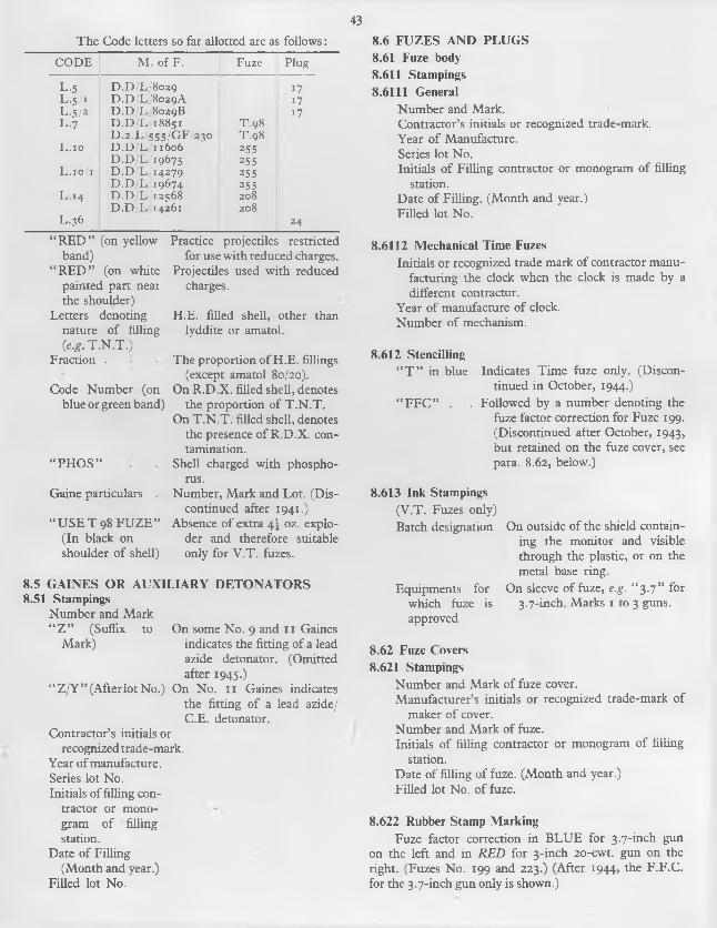
43The Code letters so far allotted are as follows:
CO D E M . o f F . Fuze Plug
L-s D.D/L/8029 17L .5 / 1 D.D/L/8029A i 7L.5/2 D.D/L/8029B 17L .7 D .D /L/18851 T.98
D.2/L/555/GF/230 T.98L . io D .D /L/11606 255
D .D /L/19675 25sL .10 /1 D .D /L/14279 255
D .D /L/19674 255L .14 D .D /L/12568 208
D .D /L/14261 208L.36 24
“ R E D ” (on yellow Practice projectiles restrictedband)
“ R E D ” (on white painted part near the shoulder)
Letters denoting nature o f filling (e.g. T .N .T .)
for use with reduced charges. Projectiles used with reduced
charges.
H.E. filled shell, other lyddite or amatol.
than
Fraction .
Code Number (on blue or green band)
“ PH O S”
The proportion of H.E. fillings (except amatol 80/20).
On R.D .X . filled shell, denotes the proportion of T .N .T .
On T .N .T . filled shell, denotes the presence o f R .D .X . contamination.
Shell charged with phospho-
8.6 FUZES AND PLUGS8.61 Fuze body8.611 Stampings8.6111 General
Number and Mark.Contractor’s initials or recognized trade-mark.Year o f Manufacture.Series lot No.Initials o f Filling contractor or monogram of filling
station.Date o f Filling. (Month and year.-)Filled lot No.
8.6112 Mechanical Time FuzesInitials or recognized trade mark o f contractor manu
facturing the clock when the clock is made by a different contractor.
Year o f manufacture o f clock.Number of mechanism.
8.612 Stencilling“ T ” in blue Indicates Time fuze only. (Discon
tinued in October, 1944.)“ F F C ” . . Followed by a number denoting the
fuze factor correction for Fuze 199. (Discontinued after October, 1943, but retained on the fuze cover, see para. 8.62, below.)
rus.Gaine particulars Number, Mark and Lot. (Dis
continued after 1941.)“ U SE T 98 F U Z E ” Absence o f extra 4] oz. explo-
(In black on der and therefore suitableshoulder of shell) only for V .T . fuzes.
8.5 G A IN E S OR A U X IL IA R Y D ETO N A TO RS8.51 Stampings
Number and Mark“ Z ” (Suffix to On some No. 9 and 1 1 Gaines
Mark) indicates the fitting of a leadazide detonator. (Omitted after 1945.)
“ Z /Y ” (Afterlot No.) On No. 1 1 Gaines indicates the fitting of a lead azide/ C.E. detonator.
Contractor’s initials or recognized trade-mark.
Year of manufacture.Series lot No.Initials of filling con
tractor or monogram o f filling station.
Date o f Filling (Month and year.)
Filled lot No.
8.613 Ink Stampings(V.T. Fuzes only)Batch designation On outside of the shield contain
ing the monitor and visible through the plastic, or on the metal base ring.
Equipments for On sleeve of fuze, e.g. “ 3 .7 ” for which fuze is 3.7-inch. Marks 1 to 3 guns, approved
8.62 Fuze Covers8.621 Stampings
Number and Mark o f fuze cover.Manufacturer’s initials or recognized trade-mark of
maker o f cover.Number and Mark of fuze.Initials o f filling contractor or monogram of filling
station.Date o f filling of fuze. (Month and year.)Filled lot No. of fuze.
8.622 Rubber Stamp MarkingFuze factor correction in B L U E for 3.7-inch gun
on the left and in R ED for 3-inch 20-cwt. gun on the right. (Fuzes No. 199 and 223.) (After 1944, the F .F.C . for the 3.7-inch gun only is shown.)

448.63 Transit Plugs
Painted Blue, indicates the presence o f an extra removable 4S oz. exploder and therefore the method of filhng is suitable for V .T . or other fuzes.
8.7 TRACERS AND TRACER-IGNITERS 8.71 Stampings
Number and Mark.Contractor’s initials or recognized trade-mark.Year o f manufacture.Series lot No.Initials o f filling firm or monogram o f filhng station. Date of filhng. (Month and year.)Filled lot No.
8.8 PACKAGES8.81 Ground Colours
“ Service” (Deep bronze, green or camouflage brown)
Light green Dark grey Red oxide Signal red
8.82 Coloured BandsYellow Packages containing ammunition made or
converted for practice purposes.White Packages containing ammunition made up
with charges giving lower velocities than Service charges, e.g., Reduced charge. The letters “ R E D ” are stencilled on the band.
8.83 Stencilling8.830 General
Standard markings are placed on ends and sides of rectangular packages and on the hds and side of cyhndrical containers.
Jungle stripes are placed on the hds only. Operational markings may be placed on top and one
long side of rectangular packages and on the side only of cyhndrical containers.
8.831 Jungle StripesThese consist of a series of diagonal yehow stripes
one inch wide and one inch apart on packages speciahy designed for use in the tropics.
8.832 Operational MarkingsThis is an abbreviated description o f the contents of
the package in large white letters stencihed over the standard markings. It is intended to provide rapid and easy identification at ports, beaches, landing grounds, etc.
The recognized abbreviations are as follows:
Abbreviation Cartridge
5 -25 A A C A R T S -25-in. M k. 2 gun, fu ll charge
3 7 A A 6 3 -7-in. M k. 6 gun, H .E . fuze 208,fu ll charge
3-7 A A H E N /S 3 7-in . M ks. 1 to 3 guns, H .E . fuze 208 or 2 14 , fu ll charge cordite N /S
3 7 A A F Z D 1 9 9 N / S 3 7-in. M ks. 1 to 3 guns, H .E . fuze 199, full charge corditeN /S
3 7 A A H E 98 N /S 3 -7-in. M ks. 1 to 3 guns, H .E .,plugged for fuze, T .9 8 fu ll charge cordite N /S
3 7 A A H E O P T 98 3 7-in. M ks. i to 3 guns, H .E ., plugged fo r fuze 208 or T .9 8 , fu ll charge
3-7 A A H E P L G D N /S 3 7-in . M ks. 1 to 3 guns, H .E . plugged, fu ll charge cordite N /S
3 7 A A F Z D 223 R E D 3 7-in . M ks. i to 3 guns, H .E . fuze 223 , reduced charge N H
3-7 A A S H O T N H 3 -7-in. M ks. 1 to 3 guns, A P shot, fu ll charge N H
40 M M P E N T 12 S E C 40 m/m gun, H .E . filled Pento- lite, N o. 14 tracer
40 M M T N T 7 S E C 40 m/m gun, H .E . filled T .N .T . , N o. 1 1 tracer
40 M M T N T 12 S E C 40 m /m gun, H .E . filled T .N .T . , N o. 14 tracer
40 M M P E N T 7 S E C 40 m/m gun, H .E . filled Pento- lite, N o. 1 1 tracer
40 M M R D X 7 S E C 40 m/m gun, H .E . filled R .D .X ., N o . 1 1 tracer
40 M M R D X 12 S E C 40 m/m gun, H .E . filled R .D .X ., N o. 14 tracer
40 M M S H O T 40 m/m gun, A .P . shot
8.833 Fraction *This is used to indicate packages not containing the
full approved complement of stores.
8.834 Packing Serial NumberThis is in white on ends of packages only.
8.835 Batch NumberThe batch letter and number, and where apphcable,
the sub-batch letter.
8.836 Filling Factory Monogram and DateAs apphcable and refers to the station which packs the
complete store.
All ammunition stores other than those mentioned below.
Smoke producing stores. Chemical filled stores. Incendiary stores.Blank cartridges.

458.837 Cartridge Details
Decoppering symbol “ D E C ”
Nature of Propellant
Lot No. o f Propellant
Mark o f Cartridge (complete round)
Placed on packages containing decoppering rounds.
Propellant code letter in a rectangle or indication letter without a rectangle.
As applicable. Where two different sizes of propellant are packed, the lot number of the smaller size is shown first.
As applicable. (Follows projectile details.) (After August, 1948.)
8.838 Projectile DetailsCalibre and nature MarkNature o f filling
Shell filling restrictions
Shell M. of F. code Shell Series No. Smoke Box symbol
Flash producer symbol
Tracer symbol
As applicable, e.g. “ 3.7 H .E.’ ’As applicable.As applicable, e.g. “ T .N .T .” ,
“ 50/50” , “ R .D .X . 3 ” , etc.Red “ X X X ” , “ X - X - X ” or
superimposed or beside indication of filling when package contains shell bearing a similar marking round the nose.
As applicable.As applicable.Green disc (with or without
“ A ” or “ B ” stencilling) to indicate presence and type of smoke box.
Aluminium paint disc to denote presence of flash producing agent in shell filling.
As applicable. To denote fitting o f shell with tracer or tracer-igniter.
8.839 Fuze DetailsFuze number and
markFuze filler and lot
No.
Fuze factor correction
As applicable, or “ P L G D ” i f plugged rounds are packed.
Initials o f fuze filler and lot No. of filled fuze, e.g., “ BR 12 3A ” .
As applicable for Fuze 199 or 223. In B L U E for 3.7-inch Mks. 1 to 3 guns (and previously in RED for 3-inch 20-cwt. gun).
8.84 Labels8.841 General
Government explosive labels and station labels are fixed on the outside o f packages and packer’s labels and batch labels on the inside.
8.842 Government Explosive Label (A.F.L. 1606)This label indicates that the package and contents
belong to the Government and that its design, quantities packed, etc., are governed by Service Regulations and not those of the Home Office.
A numeral on the label indicates the storage group to which the package belongs.
Army and Ministry o f Supply labels have a blue ground with red printing, Navy have white ground, Air Ministry and M .A.P. have a buff ground.
8.843 Station Label (A.F.L. 600)These are white muslin strips with two black fines
and letters which indicate the station or factory responsible for packing. A fist of the station monograms, as they are termed, will be found in Magazine Regulations. These are primarily sealing labels and i f found to be damaged on receipt o f the package, an examination of the contents should be carried out and the package resealed by an I.O.O. before storing.
8.844 Packers Label (A.F.L. 566A)This is a paper label containing details of the contents
of the package, place and date o f packing and the name of the packer. Fixed by shellac to the underside o f the fid it enables responsibility for deficiencies to be traced.
8.845 Batch Label (A.F.L. 97)A paper label showing full details o f the component
items used to make up the cartridge. This enables the manufacturing details o f each component item to be traced from Inspection records. It is fixed to the inside of the fid.
9. CARE, PRES ERVATION AND PREPARATION
9.1 PACKAGES 9.11 General
Packages are necessary to protect and preserve the ammunition from damage during handling, transport and storage and to facilitate handling by being made up of convenient sizes and weights.
As a general principle, all designs of packages should be suitable for service anywhere and under any conditions. This principle is now extended to embrace tropical conditions, the latest designs of packages being waterproof and proof against mould growth and attack by termites.
The contents o f packages must be securely positioned inside to prevent damage by movement.
Most packages consist o f an outer “ Box” and an inner “ Container” and the ammunition is protected from moisture, etc., by proofing either the box or its container. The complete assembly is termed the package.
The earlier boxes were mostly of wood, but steel has been widely adopted now, mainly because of the saving in space and the lessened fire risk. As wooden boxes,

46
however, can be put into production more quickly than steel ones, it frequently happens that first supplies for new types o f ammunition are made of wood until a design can be produced in steel.
The outer package is variously termed a “ Box” or “ Cylinder” , according to whether it is rectangular or cylindrical in shape. It may be provided with a liner or other internal fittings to position the ammunition and these fittings should be left with the outer package. Special outer packages are also made of wicker for use in airborne operations and are known as “ Hampers” . A canvas covering is also provided for the hamper.
The container can be removed and carried in equipment or other packages as required. Containers for fixed and separate loading Q.F. cartridges are generally made of a “ Paper” consisting either of chipboard bonded with adhesives or rolled brown paper. Containers for fuzes consist of hermetically-sealed tin “ Cylinders” .
The sealing and hence the watertightness of all packages is liable to be impaired by rough handling or bad storage.
Packages are not generally provided for projectiles of the larger calibre of separate loading ammunition, the driving bands, however are protected by grummets.(See beloio.)
Complete rounds o f fixed Q.F. ammunition are packed either fuzed or plugged. In the latter case the fuzes are bulk packed in separate boxes. V .T . fuzes are invariably packed separately.
Full details of the service packages are given in Appendices J and K.
9.12 GrummetsThe driving bands o f most separate loading pro
jectiles are protected by grummets or rings o f rope and/or canvas. These should always be kept in position during transit and storage, but must of course be removed before loading.
9.2 STORAGE9.21 Ammunition at Gun Position9.211 General
It will be extremely unlikely that anything approaching the normal explosives storehouse will be found in the vicinity of gun positions in the field, consequently storage places will usually have to be adapted or improvised.
The study o f “ Regulations for the Army Ordnance Services, Part 6, Supply of Ammunition in the Field” is recommended.
9.212 SitingReady-use ammunition will have to be placed near
the gun, but the remaining ammunition, in packages, should be sufficiently far from the guns to eliminate the risk o f an explosion involving the guns. A distance of twenty yards will suffice for this purpose, provided the dump is traversed on the side nearest the gun.
Neither the ready-use ammunition nor the main supply should be in one place. The former should be in three or four places around each gun and the latter should be sub-divided into convenient groups at least twenty yards apart. The object of this is to reduce the risk from enemy gunfire or bombing, to minimize the results of explosion and to avoid the loss o f all the ammunition at one gun or in a single battery dump by one hit.
9.213 ProtectionFor protection against enemy fire, direct sunlight and
extremes o f temperature, the best arrangement is an underground dug-out, but this may prove difficult to ventilate and keep dry. A semi-underground dug-out, having the roof and walls timbered and covered with a protective coating o f earth, is often a possibility. Timber is usually scarce, but, i f obtainable, such dug-outs can be better ventilated and kept drier than real underground dug-outs.
Recesses for ready-use ammunition are best arranged around the gun pit in which recesses are formed in the inner face at three or four places by means o f sandbags, pieces o f timber, corrugated iron, wire netting, etc., and fitted with drop curtains, preferably waterproof, although sacking is more likely to be available and does very well.
9.214 StackingFixed Q.F. ammunition recesses for ready-use
ammunition require shelves or cross supports so arranged that the cartridge is supported at two places, one being just inside the flange of the case, and the other just in front o f the normal or rear driving band.
Separate loading Q.F. cartridges i f issued in tin-lined packages or containers are best kept therein. Trench boarding or dunnage should be provided to keep them off the ground.
Shell should be piled horizontally, with the nose fuzes towards the parapet. They should be raised clear of the ground on dunnage.
9.22 Ammunition in Bulk9.221 Handling
Ammunition when issued to units is carefully packed in well-designed boxes or containers o f wood or steel. These packages enable the ammunition to withstand successfully a considerable amount o f rough usage in transport and storage. This does not, however, justify careless handling, as although the packages may not appear any the worse, such rough usage may render the contents wholly or partly unserviceable. Distortion of containers by rough usage is a common reason for the subsequent entry of moisture. Ammunition packages, therefore, should invariably be handled with reasonable care.
Ammunition packages rarely exceed i cwt. and can be carried very comfortably by two persons; consequendy there is no excuse for the packages being thrown about as they can and should be lifted and carried. When they have to
47be moved by a crane or derrick, as in loading and unloading ships, they should not be placed in nets or slung by the handles. The correct procedure is to use ammunition trays or ; ctle-boards, on which they can be carefully stacked and secured.
Should packages be badly damaged, they and their contents should be set aside for technical examination; a procedure which must also be adopted i f the package is dropped, whether any damage is apparent or not.
V .T . fuzes and auxiliary detonators are invariably bulk packed and should not be removed from their respective package until just before fuzing the shell prior to firing. Similarly, V .T . fuzes and auxiliary detonators will be removed from shell and replaced by plugs before transporting and storing. The auxiliary detonators will be removed from the fuzes and replaced by the special left-handed plugs and both fuzes and auxiliary detonators then replaced in their particular packages.
9.222 Protection9.2221 General
Packages should be kept dry, not exposed to direct sunlight and protected from extremes and particularly large and rapid changes of temperature.
9.2222 DampThe handling or movement o f packages in wet
weather should be avoided whenever possible. When this must be done, every precaution should be taken to avoid rain, snow, etc., reaching the packages.
The erection o f a tarpaulin or corrugated iron screen over the vehicle or stack and the careful covering and uncovering of the vehicle or stack as the loading or unloading proceeds, will usually afford sufficient protection.
Covered vehicles should be used whenever possible.Packages suspected of containing water should be
opened, the contents and packages cleaned and dried and the whole repacked.
Wet primers are a fruitful source o f misfires or hang- fires.
9.2223 SunAny kind o f protective covering that may be available
should be used to protect the packages against sunlight in transport and in the dump.
9.2224 Temperature VariationsAs extreme temperatures may affect the efficiency of
the ammunition, though not its safety, every possible effort should be made to obtain uniform temperature by night and day. Such conditions are only possible in the field by the use of underground or semi-underground storage. The advantages of below ground storage are so many that the co-operation o f the R.E. should be sought where necessary.
9.223 Stacking9.2231 Packages
Packages should be stacked on some form of support which keeps them at least three inches clear of the ground, one end o f every package being exposed to the air.
Both wood and steel packages can be stacked to a height o f i t feet, although a stack o f five or six feet high is the best limit to work to in the field. With small dumps, a height o f two or three feet may be found sufficient.
When above ground, storage has to be adopted, the ammunition stacks should be covered with tarpaulins, corrugated iron sheets or any other form o f improvised cover which may be obtainable. The cover should be about 12 inches above the top of the stack to provide adequate ventilation. I f the ventilation is inadequate, sweating may result. Additional ventilation may be provided during the day by raising the cover at the shady end o f the stack.
I f only a limited quantity of portable covers such as tarpaulins are available, the protection o f ammunition must have prior claim. Tarpaulins should be protected from damage by the sharp comers of packages.
9.2232 Loose Shell9.22321 General
Shell issued loose with gmmmets should usually be placed on their base on wood dunnage. I f piled or stacked horizontally, the lower tier should rest on suitable supports clear o f the ground. The pile may be four feet high.
Alternate layers o f shell should be placed head to base, special care being taken to avoid damage to driving bands.
Shell may be placed alongside cartridges or the two may be kept separate, the latter probably being the better arrangement.
Some form o f covering should be arranged i f possible in order to prevent rusting and to give protection against the sun.
9.22322 Plugged ShellWeather has very little effect on plugged shell and
they may need very little attention as long as they are well painted or free from rust.
9.22323 Fuzed ShellAs the fuze may be rendered unserviceable by damp
ness, direct sunlight or extremes of temperature, fuzed shell require more careful treatment and should be well protected. Oily rags must not be used on fuzed shell as the oil may creep into the fuze and render the explosive unserviceable.
9.3 PREPARATION9.31 General
A certain amount o f ammunition will have to be got ready at each gun for instant use. The quantity prepared
48
should be kept as low as possible consistent with operational requirements because exposed rounds are much more liable to deterioration than those in packages.
The preparation o f ready-use ammunition calls for great care to ensure that it is really ready for use and that all components are in a completely serviceable condition.
The following procedure should be adhered to as closely as possible:
Select only sound, clean and dry packages, and if possible, all from the same batch.
Open the packages methodically and carefully, taking care not to damage the contents.
I f the ready-use ammunition is to be stored in racks, recesses, etc., out of the packages, the latter should be reassembled when empty, placed under cover, and sufficient retained for use should a change in position be ordered.
The ready-use ammunition should, as far as possible, be replaced in its original package if not fired. I f it has been expended, the packages should be returned to R.A.O.C., together with all unused components.
Individual components should be examined and prepared as follows:
9.32 PrimerThe primer should not project beyond the surface of
the case. I f it does, it should be screwed home with the primer key, but i f this is not possible, the primer should be removed, another inserted and screwed home correctly, luting being applied to make a watertight joint. Only “ Luting, thick, Mk. 4 ” will be used.
The primer should always be screwed in tightly, but while it must not project beyond the surface of the case, it may lie slightly below the surface to the extent of 0.015-inch, i.e., about the thickness o f the finger nail, and still be accepted as fully serviceable.
The cap o f the primer must be clean and free fromgrit.
9.321 “ Q ” Primers (except for 40 m/m. ammunition)Not more than the threads of the primer should be
filled with luting, any excess being wiped off before inserting into the case. After insertion, also, any excess should be removed.
9.322 “ A ” Primers and all primers for 40 m/m. ammunition
Luting should be applied liberally in order to give a cushioning effect, especially with power ramming, any excess of luting being wiped off the surface after insertion.
9.33 Cartridge Case9.331 General
The case should be dry, clean, free from rust marks, cracks, dents or fluting.
9.3311 Cracks and FlutingStraight cracks not exceeding \ inch in length at the
mouth of the case can be ignored, but cracks or fluting elsewhere render the case unserviceable and the cartridge should be returned to R.A.O.C., marking the package “ Cracked cartridge case” .
9.3312 DentsSlightly dented cases may be accepted if they gauge
in the gun. (See below)
9.3313 RustRust marks from steel packages, i f slight, can usually
be removed by a lightly oiled rag, care being taken to keep the oil from reaching the primer or propellant and to wipe over the case with a dry rag afterwards.
Badly rusted cases should not be used but should be cleaned as far as possible, repacked, and i f practicable returned to R.A.O.C.
9.3314 GaugingCartridges, both fixed and separate loading, but
except those for the 3.7-inch Mk.6 gun, may be chamber gauged in the gun and should go fully home. The breech mechanism should not be closed, however, unless the striker has first been removed.
Any cartridge which fails to gauge in the gun should be tried in other guns.
Cartridges should be loaded by hand when gauging and automatic ramming gear should not be used.
Frequent gauging should be avoided as it tends to weaken the cartridge case/projectile joint.
Any cartridge failing to gauge should be repacked and returned to R.A.O.C. and the package suitably marked.
9.332 Fixed AmmunitionThere should be no movement between the case and
the projectile. Slight looseness is not harmful, provided that the cartridge will gauge in the gun, but very loose cases should be replaced in their packages and segregated pending their return to R.A.O.C.
9.333 Separate Loading AmmunitionThe closing lid should be examined to see that it is
sound, serviceable and in the proper position. Only cartridges with serviceable fids should be held for ready- use.
9.34 ProjectilesThese should be dry, clean, well painted, free from
rust and have undamaged driving bands.Rust can be removed by using a fine grade of emery
cloth or a scratch card.Unpainted surfaces o f 6-pr. projectiles and upwards
may be coated with warm “ boiled linseed oil, lead free” , using a brush, and allowed to dry. One coat is sufficient and should be applied to the unpainted parts only, otherwise the projectile may become “ high to Gauge” .
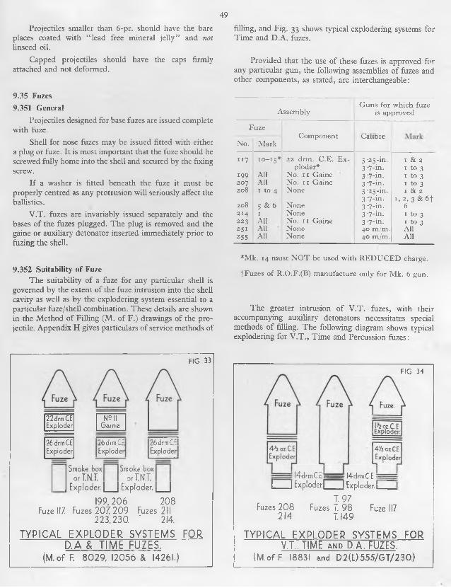
49Projectiles smaller than 6-pr. should have the bare
places coated with “ lead free mineral jelly” and not linseed oil.
Capped projectiles should have the caps firmly attached and not deformed.
9.35 Fuzes9.351 General
Projectiles designed for base fuzes are issued complete with fuze.
Shell for nose fuzes may be issued fitted with either a plug or fuze. It is most important that the fuze should be screwed fully home into the shell and secured by the fixing screw.
I f a washer is fitted beneath the fuze it must be properly centred as any protrusion will seriously affect the ballistics.
V .T . fuzes are invariably issued separately and the bases o f the fuzes plugged. The plug is removed and the gaine or auxiliary detonator inserted immediately prior to fuzing the shell.
9.352 Suitability of FuzeThe suitability o f a fuze for any particular shell is
governed by the extent o f the fuze intrusion into the shell cavity as well as by the explodering system essential to a particular fuze/shell combination. These details are shown in the Method of Filling (M. of F.) drawings of the projectile. Appendix H gives particulars o f service methods of
filling, and Fig. 33 shows typical explodering systems for Time and D.A. fuzes.
Provided that the use of these fuzes is approved for any particular gun, the following assemblies o f fuzes and other components, as stated, are interchangeable:
G uns for w hich fuze Assem bly is approved
FuzeCom ponent
N o. M ark^aiiD ie
1 1 7 10 - 15 * 22 drm . C .E . E x ploder*
5 '2 5 -in. 3 -7-in.
1 & 2 1 to 3
199 A ll N o. 1 1 G aine 3 7 -in. 1 to 3207 A ll N o. 1 1 G aine 3 -7-in. 1 to 3208 1 to 4 None 5 -2 5 -in.
3 -7 -in.I & 2
I , 2 , 3 & 6 f208 5 & 6 None 3 '7 -in. 62 14 I None 3 '7 -in. 1 to 3223 A ll N o. 1 1 G aine 3 '7 -in. 1 to 32 5 1 A ll None 40 m /m . All25s A ll None 40 m /m . A ll
*M k . 14 m ust N O T be used w ith R E D U C E D charge.
fF u z e s o f R .O .F .(B ) m anufacture only fo r M k. 6 gun.
The greater intrusion o f V .T . fuzes, with their accompanying auxiliary detonators necessitates special methods of filling. The following diagram shows typical explodering for V .T ., Time and Percussion fuzes:
22drmC.EExploder
N? II Game
26drmC.EExploder
FIG 33
26drmCE 26drmC.ElExploder Exploder
Smoke b o x S mo k e box orT.NJ. orIN.T.
Exploder. |___ | Exploder. |___ |199,206 208
Fuze 11Z Fuzes 207, 209 Fuzes 211 223,230. ' 214.
TYPICAL EXPLODER SYSTEMS FOR D.A & TIME FUZES.
(M.of F. 8029, 12056 & 14261.)
FIG. 34
I l4drm.C.E=____ . l4drm.C.E.=I I Exploder! I Exploder.il
Fuzes 208 214
T. 97 Fuzes T. 98
1149Fuze 117
TYPICAL EXPLODER SYSTEMS V.T., TIME and D.A. FUZES.
(M.of F 18831 and D2(L)555/GT/230.)
FOR

5°With these methods of filling, assemblies are inter
changeable as follows:
A ssem bly G u n s for w hich fuze is approved
Fuze
N o. M arkCom ponent Calibre M ark
208 1 to 3 4 i oz. C .E . E x ploder *
3 '7 -in. 1 to 3
T .9 7 A ll None 3 -7 -in. 1 to 3T .9 8 A ll N one 3 '7 ->n. 1 to 3T .14 9 A ll None 3 '7 -in. 1 to 31 1 7 10 to 15 4 ! oz. C .E . E x
p lod er,* plus C .E . Pellet
3 '7 -m . 1 to 3
* For Practice Projectiles, dummy exploders consisting of wooden blocks with a central flash hole or felt washers are used. C.E. exploders must N O T be used.
9.353 Fuzing and Re-Fuzing9.3531 General
The operation o f fuzing or re-fuzing projectiles requires careful supervision and should be undertaken under conditions approaching as closely as possible to “ field laboratory conditions” as defined by Regulations for the Army Ordnance Services, Part 6, Supply o f Ammunition in the Field, paras. 120 to 139 inclusive. In particular, the operation will be carried out under cover, and no fires, naked lights, lighters, matches or smoking materials will be allowed in the vicinity.
The atmospheric conditions of the hut or tent in which the operations of opening up and closing the shell are carried out must be quite dry to prevent moisture entering the shell when opened up.
All components must be perfectly dry before insertion, and only one shell at a time must be worked upon during breaking down and assembly. All operations must be carried out “ under precautions” .
In all shell operations, cleanliness and careful handling are most important and it is essential that no dirt, dust, grit or extraneous matter be allowed to enter the shell, or come in contact with any components. Before the removal of any components, therefore the exterior of the shell must be thoroughly cleaned and the components stored in perfectly clean packages until required again.
I f the round is complete, it is essential that the projectile is firmly held and the cartridge case well supported lest the projectile be loosened in the case.
Cartridge clips should always be put on to protect the primers.
To sum up, therefore, although re-fuzing is normally a laboratory job, i f the three basic principles of
D R Y N E SS C L E A N L IN E SS
CA REare observed, it can be carried out by battery personnel in a satisfactory manner.
9.3532 Tools RequiredThe correct implements should invariably be used in
order to minimize damage to ammunition and danger to personnel. The following tools should be available:
T o ol U se
C lips, Cartridge
Fu ze K e y N o. 1 19 '
Fuze K e y N o. 12 1 Fuze K e y N o. 175
Fuze K e y N o. 222
Fuze K e y N o. 223
G aine K e y N o. 69 H ook, extracting
exploders M k. 2 Im provised Scraper
or length o f wire o f non-ferrous m aterial
W rench, Rocket “ U ” , 3-in . M k. 1
3/16 -in . D rill with adjustable collar
Protection o f prim ers o f Q .F . am m unition.
Inserting and Rem oving N os. 199 and 207 fuzes.
Inserting and Rem oving N o. 1 1 7 fuze.Inserting and Rem oving N os. 208,
2 14 , T .9 7 , T .9 8 and T .14 9 fuzes.Inserting and Rem oving Plugs. R e
m oving plug from base o f N os. T .9 7 , T .9 8 and T .14 9 fuzes.
Inserting and R em oving Fuze N o. 208 made after 1945.
Rem oving N o. 1 1 Gaine.Extracting Exploders.
C learing shell cavity.
H olding shell when inserting or rem oving fuzes.
D rilling a seating for point o f fixing screw into fuze threads.
9.3533 Stores RequiredThe following stores should also be available:
Item Vocab.Section
Rem arks
Cem ent R .D . N o. i or 1 A , lead free
u T o cover recess o f screw fixing fuze after insertion o f screw.
Com position R .D . 1154
u T o fill interstices between time rings o f com bustion time fuzes and between the screwed collar, dome and body o f m echanical time fuzes.
D isc, T racin g Cloth, 1 ‘78-in . diam.
S.2 Each exploder (including the bottom exploder or smoke box, according to design) should be covered b y two o f these discs, sh iny sides together. T h e discs act as bearings when the fuze is screwed home and prevent m ovement o f the exploder.
L u ting , thin, M k. 5, lead free
u T o coat threads o f fuze before insertion and to coat threads o f fixing screw before insertion.
N aphtha u F o r dissolving R .D . cem ent when rem oving set screw fixing fuze.

5 i
9.3534 Removal of Fuze or Plug, Gaine and OtherComponents
Slip cartridge clips over the base o f the cartridges of Q.F. ammunition to protect the primer.
F ix a strap wrench or other suitable tool round the shell to hold it securely.
Carefully remove the cement covering the screw fixing fuze with a pointed tool, taking great care not to damage the threads. Should difficulty be experienced, the cement may be dissolved by the application of Naphtha for twenty-four hours. In plugged shell, the fixing screw will be found embedded in luting only.
Unscrew the fixing screw sufficiently to clear the fuze-hole threads. A screwdriver should be used with a blade narrower than the screw head.
Remove fuze or plug and any other components not required.
Inspect the cavity. This should be free from loose explosive, with no sign of cracking or powdering o f the main filling. Should a round show this defect, it should be immediately plugged up, set on one side for the I.O.O.’s examination and disposal instructions.
Inspect screw threads and make entirely free from old luting or other extraneous matter.
9.3535 Inspection and Preparation9.35351 Combustion Time Fuzes
The fuze covers should be kept on until immediately before use and not removed when preparing for ready-use. Fuzes with tight covers should preferably be used for ready-use, the covers being tested for looseness by a straight pull only and never by a twisting motion that might disturb the setting.
When the cover is removed, the setting should be checked and/or the fuze correctly set. Unless the ammunition is to be fired immediately, whenever the cover is removed, or the setting altered, R.D . composition 1154 must be rubbed into the spaces between the time rings, cap and body, and allowed to dry. Any excess composition should be wiped off while still wet. A delay of"an hour in this waterproofing may prove fatal to the serviceability of the fuze.
Wipe the threads of fuze and shell with a clean rag and coat the threads of the fuze with luting.
9.35352 Mechanical Time FuzesCheck the setting of the fuze and re-set to SA F E i f
necessary, and i f the dome has been moved, the fuze must be re-waterproofed within two hours. R.D. Composition 1154 should be worked into the junction of the screwed collar, dome and body, any excess composition being wiped off before allowing to dry.
Where there is a plain cylindrical surface below the threads of the fuze, it should be examined to ensure that the cement coating is continuous; i f not, recoat with Cement R.D . No. 1 and allow to dry.
Wipe the threads o f fuze and shell with a clean rag and coat the threads o f the fuze with luting.
9.35353 Percussion FuzesFor those fuzes provided with a safety cap, see that
the safety devices securing the cap are in position and in a fully serviceable condition so that they can be readily withdrawn and the caps removed as soon as the order to do so is received.
I f the ammunition is not to be fired immediately, any openings in the fuze should be lightly coated with R.D. Composition 115 4 or luting as a protection against moisture.
Where there is a plain cylindrical surface below the screw threads o f the fuze, it should be examined to ensure that the cement coating is continuous, and if not, it should be re-coated with Cement R.D . No. 1 and allowed to dry.
Wipe the threads o f fuze and shell with a clean rag and coat the threads o f the fuze with luting.
9.35354 V.T. FuzesRemove the required number o f fuzes and gaines
from their containers. They should be handled carefully and special care taken that they are not dropped and that any protective wax coating is not damaged.
Unscrew the bakelite plug from the base o f the fuze (this has a L E F T H AND thread). In most cases this can be unscrewed by hand. I f a tool is necessary, use Key No. 222 i f available.
Screw the gaine hand-tight into the base of the fuze, no washer being required (L E F T H AND thread).
Wipe the threads of the shell with a clean rag.
9.3536 Re-fuzing and Closing of ShellInsert the correct exploders, etc. It is important that
exploders are inserted with the marked end uppermost.Cover each exploder with two tracing cloth discs,
shiny sides together.Place a copper and asbestos washer over the fuze
threads.Screw the fuze into the shell, using the correct key.
Make certain that the fuze goes right home. No forcing should be necessary. I f the fuze body binds against the cavity wall, reject the shell or the fuze according to which is at fault. Tighten the fuze while holding the shell with a strap wrench. DO N O T H AM M ER ON T H E FU Z E K E Y H A N D LE TO T IG H T E N T H E FU Z E. Use only such pressure as can be applied by hand to the fuze key handle. I f the fuze cannot be tightened so that a good seating is obtained between the shell and fuze, reject either the shell or fuze.
It may be necessary to drill a small seating for the point of the fixing screw into the threads o f the fuze. This seating must be o f just sufficient depth to ensure that the screw will hold the fuze securely. Care must be taken not to damage the screw hole threads during this operation. A 3/16 inch drill fitted with an adjustable collar should be used for this operation.
Put a pellet of luting on the screw fixing fuze and screw home. Fill recess with R.D . Cement No. 1 , smooth off flush and allow to dry. Clean up shell externally.

52Remove cartridge clip and strap wrench and replace
round in its ready-use rack. V. T. fu zed shell must not be placed in packages although other types of fuzed shell may.
9.4 ROUTINE INSPECTIONS AT GUN POSITIONS
9.41 GeneralSystematic daily inspections should be made of all
ammunition held at gun positions. These inspections should be no less critical than the daily inspection of personnel and gun equipment. To be effective, it is essential that the inspecting officer should have a thorough knowledge o f the ammunition supplied, its use, and the details of care and preservation needed to maintain it in a thoroughly serviceable condition. The following paragraphs summarize the points to which particular attention should be paid.
9.42 Ammunition RecessesConvenient siting.Protection from direct sunlight, rain, snow, etc.No danger from flooding i f below ground level.Any ammunition which has been wetted by rain or
water and whose serviceability is suspect, should be withdrawn from ready-use and reported to I.O.O. for examination.
Effective ventilation. I f inadequate, it may be advisable to move the ammunition out into the open in dry dull weather.
Protection from small arms fire from ground and air.Reasonable protection from artillery fire, bombing
and gas.No oil, oily rags, waste, paint tins, broken glass or any
store other than the ammunition and the approved ammunition implements should be allowed in therecesses.
9.43 Ready-use AmmunitionPrimers should be flush or only slightly below the
surface of Q.F. cartridge cases.Cartridge cases should be clean, dry and free from
cracks or fluting. (The case may crack spontaneously and therefore should be examined daily.) Cases must not be oiled.
The projectile o f fixed Q.F. ammunition should be firmly attached to the cartridge case.
Projectiles should be dry, free from rust and painted or with the unpainted portions coated with linseed oil or mineral jelly according to calibre.
Driving bands should be clean and undamaged.Where safety caps are provided for D.A. fuzes, they
should be fitted.Time fuzes should be treated with R.D . 115 4 when
prepared and immediately after being set or re-set.
9.44 Ammunition in BulkAn air space of at least a foot should exist between
the ammunition stack and the walls or roof to provide ventilation.
One end of each package should be visible.Packages should be clean, free from debris or wet;
i f necessary, steel packages and separate loading projectiles (unless fuzed) can be wiped with an oily rag. Condensation or “ sweating” often occurs on steel packages and projectiles, but is not normally harmful.
I f grummets are provided they should be fitted over the driving bands.
9.5 DAMAGED AND DEFECTIVE AMMUNITION9.51 Damaged Ammunition
When ammunition arrives, whether at a dump or gun position, the packages should be carefully examined and all those damaged, any that are known to have been dropped, or suspected o f containing water, should be set aside for subsequent examination o f the contents.
Undamaged ammunition can be repacked in serviceable containers i f available, care being taken, however, to see that the markings on the packages are amended to agree with the new contents and the batch labels transferred.
I f a package has got wet, both the package and contents should be thoroughly cleaned and dried before being repacked. It must be remembered that wet primers are a fruitful source of misfires and hangfires.
Ammunition suspected of being damaged, whether by rough handling or damp, should be returned to the nearest R.A.O.C. depot, suitably marked.
9.52 Defective Ammunition9.521 General
Defective ammunition is generally manifested by misfires, blow-backs, burst cases, erratic times to burst, blinds or prematures.
Loose driving bands leading to erratic shooting and often due to a very worn gun are denoted by a howling sound, and unsteadiness, due mainly to the same cause, is evidenced by a swishing sound.
All defects are the direct result o f either the ammunition or equipment suffering from one or more o f the following
MisuseNeglectDefect
The remedy for the first two is obvious, but that for the last is seldom apparent and necessitates lengthy investigation. The success or otherwise of investigations depends primarily upon the evidence available and every effort should be made to obtain first-hand evidence immediately. This must be done “ before the blood is d ry” .
The fullest possible details are required of the markings of defective ammunition and the packages from which it was taken. The actual packer’s and batch labels should be retained.
Arrangements should be made for the retention of all evidence, whether material or personal, until the investigation has been completed.

53Full details o f the action to be taken in the event o f an
accident (including prematures, whether inside or outside the bore) are contained in Regulations for Army Ordnance Services, Part 7, Pamphlet No. 5. As an accident may occur at any hour of the day or night, these regulations should be familiarized and be available for consultation at any time.
9.522 Misfires, Blow-backs and Burst CasesAll evidence, including the actual primer and cart
ridge, either unfired or fired, must be available for examination and the subsequent investigation.
Primers which have been struck, but which have not fired, are liable to be sensitive to shock, and accidents may occur i f such rounds are put with serviceable ammunition. Therefore, in no circumstances mill a round fitted with a misfired primer be transported by road or rail, NO R will it be mixed with serviceable ammunition.
When returning ammunition to the R.A.O.C., a certificate will be rendered to the effect that there are no rounds fitted with misfired primers in the consignment and no such consignment will be accepted by the R.A.O.C. without such a certificate signed by the consigning officer.
Misfired rounds will be disposed o f as followsI f spare primers are held, the primer will be
changed.I f spare primers are not held, the misfired
primer will be removed, the primer hole will be plugged (a fired primer can be used for this) and the round set aside pending the insertion o f a new primer.
I f for any reason it is impossible to remove a misfired primer, the round will be set aside for destruction by the I.O.O. It will not, in any circumstances be stored amongst serviceable ammunition.
Misfired primers will be reported to the local 1 .0 .0 . who will arrange destruction.
9.523 PrematuresMost of the evidence is destroyed although circum
stantial evidence will be available by taking details of the next round that would have been fired but for the premature. Particulars o f the shell burst are most valuable. The nature of the burst, including position, noise, appearance and the colour o f the smoke and the presence or absence of strike marks on the ground should be noted. An immediate search should also be made for all shell and fuze fragments. I f the guns are by the sea-shore, the strike of fragments can often by seen by splashes and it may be possible to recover fragments if a thorough search is made directly the tide recedes. Fragments should be retained for subsequent expert examination and a sketch made to show where they were recovered in relation to the gun.
Evidence o f actual fuze setting, bearing and Q.E., are also most valuable and although difficult to obtain in the case o f remote power gun control and automatic loading,
fuze-setting and firing, every effort should be made to record even approximate values.
Equipment damaged as a result of a premature, which in the opinion o f R .E .M .E., warrants further examination, will be despatched to C.I.A . under arrangements to be made by D .D.O .S. Command.
9.524 Blinds9.5241 General
Evidence in these cases will be mostly negative, but such information is none the less valuable. Further and important information is often obtained by examination of these rounds after they have fallen and have been located.
9.5242 DisposalA.A. shell which fail to burst in the air or on impact
with the ground, frequently fall in friendly territory and have to be disposed of under precautions. There is some risk attached to handling blind H.E. shell, and only trained personnel should deal with them. Disposal is normally carried out by the R.A.O.C., but the R.A. may have to handle blinds, therefore the following notes may be helpful as a guide.
When a blind shell is located, an area within twenty yards’ radius should be cleared whilst the work of disposal proceeds. The greatest risk of the shell bursting is i f it is moved or struck.
I f the shell is in open ground, i.e., clear for fifty yards’ radius, the earth should be cleared sufficiently to apply a a demolition charge and blow it up. This is done by laying a slab o f guncotton, C.E. or T .N .T . on the shell, with primer and detonator fitted. The detonator should have at least three feet of safety fuze attached. Place a partly filled sandbag over one end of the slab to keep it in position, light the safety fuze with a fuzee and retire under cover. After the explosion occurs examine the hole and remove the residue of the shell.
Should an H .E. shell be lying in a street or building where destruction in situ is not practicable, its removal requires care as there is some risk o f explosion. Other types of shell or shot are practically safe for removal. An H.E. shell may, however, have the detonator pierced by the striker or at any rate be fully armed and so function on movement. As H.E. shell are fitted with safety shutters, there is a strong possibility o f the shutter having closed under action of the shutter spring so that the firing o f the detonator is not likely to affect the filling. When a shutter is not fitted with a spring it may not return to the safe position. Particular care should be taken with ammunition fired from American equipment as most o f these shutters are designed to lock in the armed position in flight and thus remain armed. A study o f the fuze and gaine drawings will indicate what is likely to happen.
To reduce the risk of removal to a minimum, scrape the earth clear of the fuze. I f the time fuze is set SA FE, or if the gas escape discs of combustion time fuzes are not blown out, the shell should be safe to move, although this
E
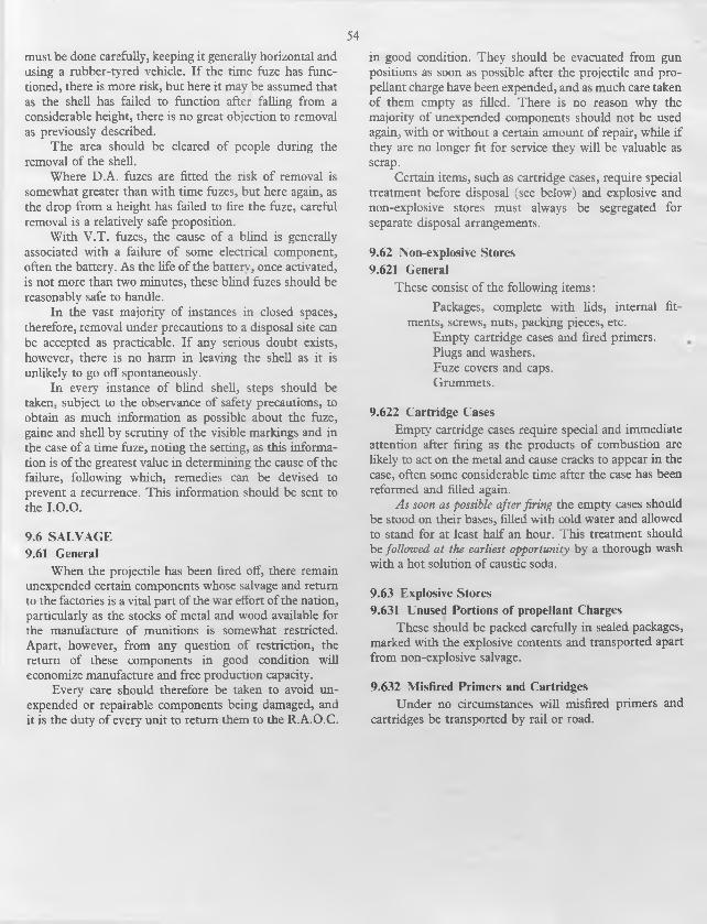
54must be done carefully, keeping it generally horizontal and using a rubber-tyred vehicle. I f the time fuze has functioned, there is more risk, but here it may be assumed that as the shell has failed to function after falling from a considerable height, there is no great objection to removal as previously described.
The area should be cleared of people during the removal of the shell.
Where D.A. fuzes are fitted the risk o f removal is somewhat greater than with time fuzes, but here again, as the drop from a height has failed to fire the fuze, careful removal is a relatively safe proposition.
With V .T . fuzes, the cause o f a blind is generally associated with a failure o f some electrical component, often the battery. As the life o f the battery, once activated, is not more than two minutes, these blind fuzes should be reasonably safe to handle.
In the vast majority of instances in closed spaces, therefore, removal under precautions to a disposal site can be accepted as practicable. I f any serious doubt exists, however, there is no harm in leaving the shell as it is unlikely to go off spontaneously.
In every instance o f blind shell, steps should be taken, subject to the observance o f safety precautions, to obtain as much information as possible about the fuze, gaine and shell by scrutiny o f the visible markings and in the case o f a time fuze, noting the setting, as this information is o f the greatest value in determining the cause o f the failure, following which, remedies can be devised to prevent a recurrence. This information should be sent to the I.O.O.
9.6 SALVAGE 9.61 General
When the projectile has been fired off, there remain unexpended certain components whose salvage and return to the factories is a vital part of the war effort o f the nation, particularly as the stocks o f metal and wood available for the manufacture o f munitions is somewhat restricted. Apart, however, from any question o f restriction, the return of these components in good condition will economize manufacture and free production capacity.
Every care should therefore be taken to avoid unexpended or repairable components being damaged, and it is the duty o f every unit to return them to the R.A.O.C.
in good condition. They should be evacuated from gun positions as soon as possible after the projectile and propellant charge have been expended, and as much care taken o f them empty as filled. There is no reason why the majority of unexpended components should not be used again, with or without a certain amount of repair, while if they are no longer fit for service they will be valuable as scrap.
Certain items, such as cartridge cases, require special treatment before disposal (see below) and explosive and non-explosive stores must always be segregated for separate disposal arrangements.
9.62 Non-explosive Stores9.621 General
These consist of the following items:
Packages, complete with lids, internal fitments, screws, nuts, packing pieces, etc.
Empty cartridge cases and fired primers. Plugs and washers.Fuze covers and caps.Grummets.
9.622 Cartridge CasesEmpty cartridge cases require special and immediate
attention after firing as the products o f combustion are likely to act on the metal and cause cracks to appear in the case, often some considerable time after the case has been reformed and filled again.
As soon as possible after firing the empty cases should be stood on their bases, filled with cold water and allowed to stand for at least half an hour. This treatment should be followed at the earliest opportunity by a thorough wash with a hot solution o f caustic soda.
9.63 Explosive Stores9.631 Unused Portions of propellant Charges
These should be packed carefully in sealed packages, marked with the explosive contents and transported apart from non-explosive salvage.
9.632 Misfired Primers and CartridgesUnder no circumstances will misfired primers and
cartridges be transported by rail or road.

Fuze Detonators
Star S h e ll-----r
T racers
Sm oke B o x -
T racers
N on-lum inousself-destruction
oq3- a as3 o
Prim er Caps
T u b es
-3 — Prim ers
3(JQ
Fuzes
Shrapnel Shell
Star Sh ell
Cartridges as *“ * "B as crq 3 n 7?
Cartridges
Fuze Detonators
G aine Detonators
G aine M agazines
Exploders
C artridges—
2o °cL2L n 3*tt F.
cooEcrq’
3* £
o goI s
I f "§'§
Shell Filling
EX
PL
OS
IVE
S A
ND
T
HE
IR U
SE
S
Exp
losives'

56A p p e n d i x B
P R O P E L L A N T C O M P O S IT IO N
T yp e
S3
3OQ
C3 ^ l-l<DC <uI"
c3u
<t> ° os 3 t£m 13 c(U u O
t § i■ S L3 03« Z U
N om enclature
OldCodeLetter
Com position (per cent.)
Rem arks
Base Stabilizer FlashReducer
M ode-rant M isc .
Nit
ro-c
ellu
lose
Nit
ro-g
lyce
rin
e<u
'u
£
Min
eral
jell
y
Car
bam
ite
D.P
.A*
D.B
.T.*
Dia
myl
ph
thal
ate
Po
tass
ium
su
lph
ate
or
nit
rate
Po
tass
ium
cry
olit
e'
*yzQ G
rap
hit
e
M k i 37 58 5 Original“ C o rd ite”
R D B C , F 52 42 6
M D D , F 65 30 5
M C D 65 3 ° 5
W E 65 29 6 0 4 chalk
W M E 65 29 ‘5 3 '5 2 0 4 chalk
S C S 49 5 4 1 5 9 0-35 chalk N O N Eunless speciallyordered
Bofors J 66-6 26 0 1 "5 0-7 5-2
N A 19 18-7 5 4 ’7 7 '3 •3 Previously“ R D N ”
N C T N 99 ‘5 •5
N H O 86 I 3 IO D upont Form ula
F N H L 84 I 5 IO > j >>
F N H /P L 83 1 5 1 IO
* N O T E : D .P .A . (Diphenvlam ine). Chem ically com bines with nitrous fum es given o ff by deterioration o f nitrocellulose.
D .B .T . (D ibutylphthalate). Cooling agent, and being oily it counteracts the hygroscopicity o f nitrocellulose.
D .N .T . (Dinitrotoluene). Controls burning rate and reduces hygroscopicity o f nitrocellulose.

A p p e n d i x CP R O P E L L A N T N O M E N C L A T U R E
57
L etter Exam ples Significance Rem arks
None M k. 1 Cordite
A A Flashing cordite based on soluble cotton nitro- Contains D N T and cooler than W or W Mcellulose -
B R D B “ B ” form ula o f Research D epartm ent
C C D Carbamite (“ D ” form ula)
M C Cracked (M ineral Jelly)
S C Cordite (Solventless)
su/c Cog cross-section O nly applicable to S U . Follow s /K or /P
D S U D D rilled O nly applicable to S U
D B F N H /D B Double Base (Cordite)
F FQ Flashless nitrocellulose based on soluble woodnitrocellulose
G S U G G rooved O nly applicable to S U
H H S C / T Hotter O blique stroke previously omitted
IK H S C / K /T Potassium C ryolite added (flash reducer) “ K ” ^ P otassium . O blique stroke previouslyomitted
M M D M in eral Je lly (“ D ” form ula)
W M M odified (“ W ” form ula)
N /M M ulti-tubular (7 holes) C ut into short lengths or “ g ra in s” . Follow s /Kor /P
N N /P/S Flashless cordite based on insoluble cotton nitro-cellulose
N C N C T Nitrocellulose (tubular)
N H F N H N on-hygroscopic (flashless)
P F N H /P Potassium Sulphate or N itrate added (flash- reducer)
Q N Q Hotter
R N Q /R Ribbon Follow s /K or /P
R D R D B Research Departm ent (“ B ” formula)
S S C Solventless (Cordite)
N /S Slotted tube Follow s /K or /P
S G S U / S G Slotted tube, grooved O nly applicable to S U . Follow s /K or /P
I T W M /T Tubular Precedes /K or /P. O blique stroke previouslyomitted
U S U Rockets . Unrotated projectiles
w W M T “ W " form ula W — Waltham Abbey
X su/x Cruciform cross-section O nly applicable to S U . Follow s /K or /P
N O T E : Certain Am erican propellants have nom enclatures denoting the form ula only and are therefore not descriptive. An exam ple o f this is M 4 X , a double-base “ p o w d er” in the form o f irregular spherical grains

58A p p e n d i x D
C O M P O S IT IO N ' O F H IG H E X P L O S IV E S
Class
A pproxim ate Percentage o f Constituents
Rem arksNom enclature
Explosives
Com position
Com ponents
Heat and Flam e
F ric tion
Des
ensi
-ti
ser.
F.O
.M.
Lea
d a
zid
e
Lea
dSt
yph
nat
e
C.E
.
R.D
.X.
P.E
.T.N
.
T.N
.T.
Am
mo
niu
mN
itra
te
Po
tass
ium
Ch
lora
te
An
tim
on
ySu
lph
ide
Alu
min
ium
Po
wd
er
Mea
led
(G
un
) P
ow
der
Su
lph
ur
Po
wd
ered
Gla
ss
Wax
Init
iato
rs
Dis
rup
tive
F .O .M . .
L ead Azide
L ead Styphnate
A .S .A . D etonating Com position
IOO
IOO
65
IOO
33 2
Fulm inate o f M ercu ry
N ot used alone
Ign
ifer
ou
s
DetonatingCom positions“ A ”“ B ”“ C ” .
Q .F . C om position
38I I32
37 53 45
38
253623
56 2 2 2
Inte
r med
iari
es C .E . or T etry l
Pentolite .
T .N .T . .
IOO
5 ° 50
IOO
Com positionExploding
Bu
rsti
ng
char
ges
Am atol 80/20 . .. 5 0 /5° •
T .N .T . .
Pen /D i .
Pentolite .
R D X /B W X .
R D X / T N T .
R D X
91
5°
93
50
2050
IOO
50
50
O O00 lo
7
9
T ri-n itro-toluene
,/BWX = Beeswax
N ot used alone

59A p p e n d i x E
C A R T R I D G E S
5 -2 5 - i n . M k . 2 G u n
(W here m ore than one item is shown below, these are alternatives)
Charge M arkBrassCaseM ark
L id
M arkPrim er
N o. Igniter
PropellantM ethod o f F illing D esign N um ber
NatureN ature and
SizeW eight
lb. oz. dr.
F 1 2 W hitemetal 2 17 N o. 61 N /P/S 263-066 24 12 0 D D /L /1350 5
F 2 2*3
W hitemetal 2 17 N o. 61 N /P/S 263-066 24 12 0 D D /L /1350 5
F 3 j 3/1 Plastic 3 17 N o. 61 N /P/S 263-066 24 12 0 D 2/L /29 7 1 /G F /i 14
3 -7 - i n . M k . 6 G u n
BrassCaseM ark
PropellantC M . o f F . D esign N o. D D / L / 15 3 4 2 w ith Fo il
ProjectilePlugFuzeHoleN o.
Charge M ark Prim erNo.
Igniter FuzeM ethod o f N o.
Filling D esign N um berNature and Size
W eight FilledM ark
lb. oz. dr.
H .E . Shell
F A 1 9 F N H /P 061 17 4 8 4C D D /L /14 2 6 1 24
F 2C 1 F N H /P 061 i 7 4 8 4C D D / L / l4 2 6 l ; 208
F 3 C 1 9 N /P /M 061 17 2 O 4C D D / L / l4 2 6 l 208
F 4C 1 9 N /2P/M 055 17 6 O 4C D D / L / l4 2 6 l 208
F 5 1 9 F N H /P 061 17 4 8 4/1 D 2/L /555/G F /230 24
Practice Projectile
F 1 1 9 N /2P/M 055 17 6°
I D 2/L/2424/G F/230
24
3 '7 - i n . M k s . 1 - 3 G u n s
PropellantM . o f F . D esign N o.
D D / L / 7 8 3 1A w ith Fo il
Projectile
Charge M arkBrassCaseM ark
Prim erN o.
IgniterN o.
FilledM ark
M ethod o f F illin g D esign N um ber
G aineN o.
FuzeN o.
PlugFuzeH oleN o.N ature and
Size
W eight
J lb. oz. dr.
H .E . ShellF A I I I W 1 2 4
W M 13 0 7I 8 iC D D /L/8029
D D /L /120 56I I 17
F C I I I 3789
N H 050 8 9 8 iC D D /L/8029D D /L /12 0 56
1 1 17
F D I I I 39 N /S 164-048 8 8 O i C | D D /L/8029 D D /L /120 56
I I 17
F iC I I I W 124 W M 130
7 I 8 iC D D /L/8029 D D /L / 120 56
I I i 199

6o
3 '7 - i n . M k s . 1 - 3 G u n s
(W here m ore than one item is show n below, these are alternatives)
Propellant ProjectileM . of F . D esign No.
Brass D D /L /7831A w ith Foil PlugCharge M ark Case Prim er Ign iter ---------------------- Filled M ethod of Filling Gaine Fuze Fuze
M ark ■ No. No. W eight M ark Design N um ber No. No. HoleN ature and No.
Size lb. oz. dr. -
H .E . Shell
F aC I 1 1 W 12 4 W M 130
7 I 8 iC D D /L/8029D D /L /12 0 56
I I 207
F 5C I 1 1 3789
N H 050 8 9 8 iC D D /L/8029D D /L /12 0 5 6
I I 199
F 6C I II 3789
N H 050 8 9 8 iC D D /L/8029D D /L /12 0 56
I I 207
F 7C I 1 1 39 N /S 164-048 8 8 O iC D D /L/8029D D /L /12 0 56
I I 199
F 8C I 1 1 39 N /S 164-048 8 8 O iC D D /L/8029D D /L /12 0 56
I I 207
F 9C I II 37 F N H /P 049 9 O 2 iC D D /L/8029D D /L /12 0 5 6
I I i 99
F i iC I 1 1 W 12 4 W M 130
7 * 8 iC D D /L /14 2 6 1 208
F I2 C I 1 1 3789
N H 050 8 9 8 iC D D /L /14 2 6 1 208
F 1 3 c I II 39 N /S 164-048 8 8 O iC D D /L /14 2 6 1 208
F 1 4 c I 1 1 37 F N H /P 049 9 O 2 iC D D / L /14 2 6 1 208
F 1 6 c I II 39 N /S 164-048 8 8 O !####£5
D D / L /18 8 5 I 29
F 1 8 c I II 89 N H 050 8 9 8 tC D D /L/8029 I I 223
F 1 9 c I II 39 N /S 164-048 8 8 O iC D D /L /14 2 6 1 2 14
F 20C I 1 1 39 N /S 164-048 8 8 O iC D D /L/8029 I I 223
F 21 I 1 1 89 F N H /P 049 9 O 2 I D D /L /14 2 6 1 2 14
F 22 I II 39 N /S 164-048 8 8 O !####£ D D / L /18 8 5 1D 2/L /555/G F /230
2 14
F 23 I 11 W 164 W M 13 0
7 I 8 iC D D /L /14 2 6 1 2 14
F 24 I 1 1 N H 050 8 9 8 iC D D /L /14 2 6 1 2 14
R iC I 1 1 W 057 W M 061
3 2 IO iC D D /L/8029D D /L /12 0 5 6
I I 199
R 3 c I 11 N H 033 3 i s O iC D D /L/8029D D /L /12 0 5 6
I I i 99
R 4C I 1 1 N C T 033 3 IS O iC D D /L/8029D D /L /12 0 5 6
I I i 99
R SC 1 I 9 74 N 045 3 13 O iC D D /L/8029D D /L /12 0 5 6
I I 223
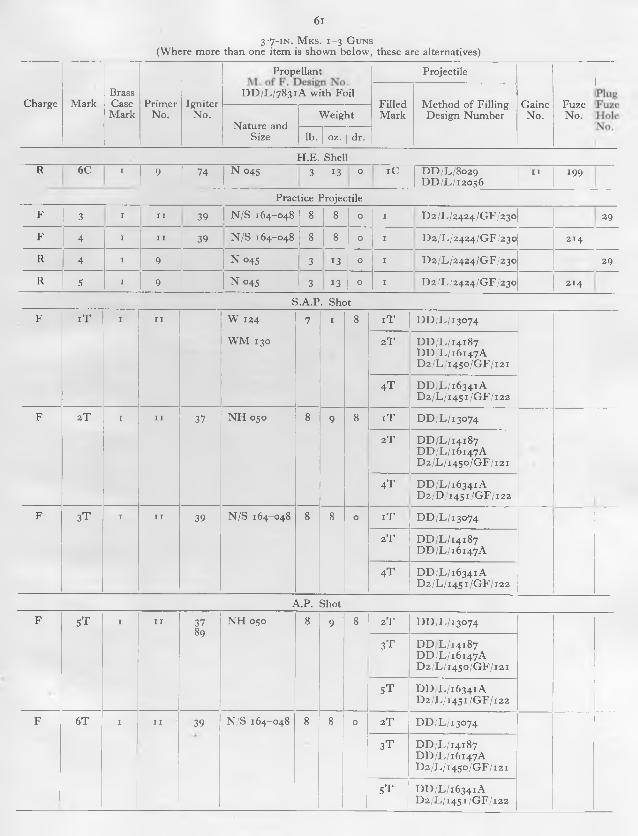
6 i
3 '7 - i n . M k s . 1 - 3 G u n s
(W here m ore than one item is shown below , these are alternatives)
Propellant Projectile
Charge M arkBrassCaseM ark
Prim erN o.
IgniterN o.
D D / L / 7 8 3 1A w ith FoilF illedM ark
M ethod o f F illin g D esign N um ber
G aineN o.
FuzeN o.
N ature and Size
W eight
lb. oz. dr.
H .E . ShellR 6C I 9 74 N 045 3 13 O tC D D /L/8029
D D /L /120 56I I 199
Practice Projectile
F 3 I I I 39 N /S 164-048 8 8 O I D 2/L /24 24 /G F /230 29
F 4 I I I 39 N /S 164-048 8 8 O I D 2/L /24 24 /G F /230 2 14
R 4 I 9 N 045 3 13 O I D 2/L /24 24 /G F /230 29
R S I 9 N 045 3 13 O I D 2/L /24 24 /G F /230 2 14
S .A .P . Shot
F i T I I I W 124
W M 130
7 I 8 i T D D /L /13 0 7 4
2 T D D / L / 14 18 7D D / L / 16 14 7 AD 2 /L / 14 5 0 /G F /12 1
4 T D D / L / 16 3 4 1AD 2 / L / i4 5 r / G F / i2 2
F 2 T I I I 37 N H 050 8 9 8 i T D D /L /130 7 4
2 T D D / L / 14 18 7D D / L / 16 14 7 AD 2 /L / 14 5 0 /G F /12 1
4 T D D / L / 16 3 4 1AD 2 /D / 14 5 1/ G F / 12 2
F 3T I I I 39 N /S 164-048 8 8 O i T D D /L /130 7 4
2 T D D / L / 14 18 7D D / L / 16 14 7 A
4 T D D / L / 16 3 4 1AD 2 / L / 14 5 1/ G F / 12 2
A .P . Shot
F S T I I I 3789
N H 050 8 9 8 2 T D D /L /13 0 7 4
3T D D L / 14 18 7D D / L / 16 14 7 AD 2 /L / 14 5 0 /G F /12 1
S T D D L / 1 6 3 4 1 AD 2 / L / 14 S 1/ G F / 12 2
F 6 T I I I 39 N /S 164-048 8 8 0 2 T D D /L /130 7 4
3T D D / L / 14 18 7D D / L / 16 14 7 AD 2 /L / 14 5 0 /G F /12 1
5 T D D / L / 16 3 4 1AD 2 /L / 14 S 1/G F /12 2

62
3.7 in . M k s . 1 - 3 G uns(W here m ore than one item is shown below, these are alternatives)
Brass
J
Charge M ark Case Prim er IgniterM ark N o. N o.
PropellantM . o f F . D es. N o. D D /L .
7 8 3 1A w ith Foil
N ature and Size
W eight
b. dr.
ProjectileI
PlugG aine i Fuze Fuze
Filled M ethod o f F illin g N o . I N o. HoleM ark D esign N o. N o.
A .P .C .B .C . ShotF I I I I 37 N H 055 9 I I o l i I D 2 /L / 14 5 2 /G F /2 18
89
Practice Shot
4 0 m .m . G u n
(Where more than one item is shown below, these are alternatives)
Charge M arkBrassCaseM ark
Prim erN o.
PropellantM . o f F . D es. N o. C IA /A . 347
w ith Foil
Projectile
FuzeN o.
T racerFilledM ark
M ethod o f F illing D esign N o.N ature and Size
W eight
oz. dr.
H .E . Shell
F 4 T 1I*2
18 W T 120-040 W N T 124-040
9 0 2 T4 T6 T
D D /L /9578 A 2 5 1 N o. 12
F S T 1I *2
18 N H 023 H N 025
IO 14 2 T4 T6 T
D D /L/9578 A 2 5 1 N o. 12
F 7 T I*234
12 W T 120-040 W M T 124 -0 4 0
9 0 2 T4 T6 T
D D /L/9578 A 251 N o. 12
F 8 T 1*234
12 N H 023 H N 025
IO H 2 T4 T6 T
D D /L/9578 A 2 51 N o. 12
F 10 T 11*2
18 W T 120-040 W M T 124-040
9 0 2 T4 T6 T
D D /L /116 0 6D D /L /13 6 7 4D D /L /19 6 75
2 5 1 N o. n
F 1 1 T 11*2
18 N H 023 N H 025
IO 14 2 T4 T6 T
d d /l /i i 6o6D D /L /13 6 7 4D D /L /19 6 75
2 5 1 N o. 1 1

C A R T R I D G E S 4 0 m .m . G u n
6 3
(Where more than one item is shown below, these are alternatives)
Charge M arkBrassCaseM ark
Prim erN o.
PropellantM . o f F . D es. N o. C IA /A . 347
w ith Foil
Projectile
FuzeN o.
T racerFilledM ark
M ethod o f Filling D esign No.N ature and Size
W eight
oz. [ dr.
H .E . Shell
F 1 2 T 1 * 12234
W T 120-040 W M T 124-040
9 O 2 T4 T6 T
d d /l /i i 6o6D D /L /13 6 7 4D D /L /19 6 75
251 N o. n
F 1 3 T I # 12234
N H 023 N H 025
IO H 2 T4 T6 T
D D ./L/i 1606 D D /L / 13 6 7 4 D D /L /19 6 75
2 5 1 N o. 1 1
F 1S T 11 *2
18 F N H /P 022 I I 12 2 T4 T6 T
D D / L / n 6 o 6D D /L /13 6 7 4D D /L /19 6 75
2 5 1 N o. 1 1
F 16 T 1*234
12 F N H /P 022 I I 12 2 T4 T6 T
D D / L / i 1606 D D /L / 13 6 7 4 D D /L /19 6 75
2 5 1 N o. 1 1
F 1 7 T1 *2
18 F N H /P 022 I I 12 2 T4 T6 T
D D /L /9 5 7 8 A 251 N o. 12
F 18 T 1*234
12 F N H /P 022 I I 12 2 T4 T5 T6 T
D D /L/9578A 2 5 1 N o. 12
F W T 11*2
18 F N H /P 022 I I 7 2 T4 T6 T
D D /L /14 2 79D D /L /19 6 74
251 N o. 14
F 2 0 T 11*2
18 N H 023 N H 025
IO 9 i 2 T4 T6 T
D D /L /14 279D D /L /19 6 74
2 5 1 N o. 14
F 2 l T 11 *2
18 W T 120-040 W M T 124-040
8 12 2 T4 T6 T
D D /L /14 2 79D D /L /19 6 7 4
2 5 1 N o. 14
F 2 2 T 1*234
12 F N H /P 022 I I 7 2 T4 T6 T
D D / L /1 4 2 7 9D D /L /19 6 7 4
2 5 1 N o. 14
F 2 3 T 1 *234
12 N H 023 N H 025
IO 9 i z T4 T6 T
D D /L /14 2 79D D /L /19 6 74
251 N o. 14
F 2 4 T 1234
12 W T 120-040 'W M T 124-040
8 12 2 T4 T6 T
D D /L /14 2 79D D /L /19 6 7 4
251 N o. 14
F 26 T 1234
12 F N H /P 022 I I 7 2 T4 T6 T
D D /L /14 2 79D D /L /19 6 74
/
255 N o. 14

64C A R T R I D G E S
4 0 m .m . G u n
(Where more than one item is shown below, these are alternatives)
PropellantM . o f F . D es. N o. C IA /A . 347
w ith Foil
Projectile
Charge M arkBrassCaseM ark
Prim erN o.
FuzeN o.
T racer
N ature and SizeW eight Filled
M arkM ethod o f Filling
D esign N o.-oz. dr.
H .E . ShellF 2 7 T I *
234
12 F N H /P 022 I I 12 2 T4 T6 T
D D /L /116 0 6D D /L /13 6 7 4D D /L /19 6 7 3
255 N o. 1 1
F 29 T 1*234
12 F N H /P 022 I I 12 S T7T
D D / L / 116 0 6D D /L /13 6 7 4
255 N o. 1 1
F 3° T 1*234
12 F N H /P 022 I I 7 5T7t
D D /L /14 2 79 255 N o. 14
F 3 i T 11 *2
18 F N H /P 022 I I 7 2 T4T6 T
D D /L /14 2 79D D /L /19 6 74
255 N o. 14
F 33 T 1 *234
12 F N H /P 022 I I 12 2 T4T6 T
D D /L/9578A 255 N o. 12
F 34 T 1 *234
12 N H 023 N H 025
IO 14 2 T4 T6 T
D D /L/9578 A 255 N o. 12
F 3 S T 1 *234
12 N H 023 N H 025
IO 9 i 2 T4 T6 T
D D /L/9578A 255 N o. 14
F 36 T 1i *2
18 F N H /P 022 IO 7 5 T7 t
D D /L /14 2 79 251 N o. 14
F 37 T 11*2
18 F N H /P 022 I I 12 2 T4 T6 T
D D /L /116 0 6D D /L /13 6 7 4D D /L /19 6 75
255 N o. 1 1
F 4 0 T 11 *2
18 F N H /P 022 I I 7 S T7 T
D D /L /14 2 79 255 N o. 14
F 4 1 T 11 *2
18 F N H /P 022 I I 12 5 T7 T
D D /L /116 0 6D D /L /13 6 7 4
255 N o. 1 1
F 4 2 T 11*2
18 N H 023 N H 025
IO 9 i 2 T4 T6 T
D D /L /14 2 79D D /L /19 6 74
255 N o. 14
F 4 3 T | 1 *2
34
12 N H 023 10 N H 025
14 2 T4 T6 T
D D /L /116 0 6D D /L /13 6 7 4D D /L /19 6 75
255 N o. 1 1

65C A R T R ID G E S
4 0 m .m . G u n
(W here m ore than one item is shown below, these are alternatives)
PropellantM . o f F . D es. N o. C IA /A . 347
w ith Foil
Projectile
BrassCharge M ark Case
M arkPrim er
N o.FuzeN o.
T racer
N ature and SizeW eight Filled
M arkM ethod o f F illin g
D esign N o.oz. dr.
H .E . ShellF 4 4 T I*
234
12 N H 023 N H 025
IO 14 S T7T
D D / L / i 1606 D D /L /136 7 4
255 N o. 1 1
F 45 T 1 * 12 N H 023 IO 9 i 5T D D /L /14 2 79 255 N o. 142 N H 025 7T
4
F 4 6 T 1 18 N H 023 IO H 2 T D D /JL/i 1606 255 N o. 1 11 * N H 025 4 T D D /L /13 6 7 42 6 T D D /L /19 6 75
F 4 7 T 1 18 N H 023 IO 14 S T d d /l /i i 6o6 255 N o. 141*2
N H 025 7 T D D /L /13 6 7 4
F 4 8 T 1 18 N H 023 IO 9 i 5 T D D /L /14 2 79 255 N o. 1 1
2N H 025 7 T
F 53 3 12 N H 023 IO 9 i 4 D D /L /19 6 7 4 255 N o. 144 N H 025
Practice ProjectileF 3T I
1 *2
18 W T 120-040 W M T 124 -0 4 0
9 O 2 T D D /L /124 0 9 2 5 1 N o. 12
F 4 T 1*234
12 W T 120-040 W M T 124-040
9 O 2 T D D /L /124 0 9 2 5 1 N o. 12
F S T 1I*2
18 W T 120-040 W M T 124-040
9 O 3T D D /L /1356 8 2 5 1 N o. 1 1
F 6 T I*234
12 W T 120-040 W M T 124-040
9 O 3T D D /L /1356 8 2 5 1 N o. 1 1
F 7 T 1i #2
18 W T 120-040 W M T 120-040
9 O 6 D D /L /14 4 79 2 5 1 N o. 1 1
F 8 T 1*234
12 W T 120-040 . W M T 124-040
9 - O 6 D D /L /14 4 79 2 5 1 N o. 1 1
F 9T 1i *2
18 F N H /P 022 I I 12 6 D D /L /14 4 79 251 N o. 1 1

6 6
C A R T R ID G E S4 0 m .m . G u n
(W here m ore than one item is show n below, these are alternatives)
PropellantM . o f F . D es. N o. C IA /A .
w ith Foil347
Projectile
Charge M arkBrassCase
M arkPrim er
N o.FuzeN o.
T racer
N ature and SizeW eight Filled
M arkM ethod o f Filling
D esign N o.oz. dr.
Practice Projectile
F 10 T 1*234
12 F N H /P 022 I I 12 6 D D /L /14 4 79 2 51 N o. 1 1
F 1 S T t*234
12 F N H /P 022 I I 7 9 T D D /L /170 6 2 2 51 N o. 14
F •7 1 *234
12 N H 025 IO 14 6 D D /L /14 4 7 9 255 N o. 1 1
F 18 1234
N H 025 IO 14 6 D D /L /14 4 79 2 5 1 N o. 1 1
S .A .P . Shot
F I I1 *2
18 W T 144-048 W M T 148-048
IO 1 2 I N o filling
F 2 T 1*234
12 W T 144-048 W M T 148-048
IO 1 2 I N o filling
F 3 T 1I *
2
l 8 W M T 2 1 1 - 1 0 0 1 1 4 3 D D /L /13 0 7 4D D / L / 16 14 7 8
C avity
4 D D / L / 14 18 7D D / L / 16 14 7 AD 2 /L / 14 5 0 /G F /12 1
F 4 T 1*2
34
12 W M T 2 1 1 - 1 0 0 1 1 4 3 D D /L /13 0 7 4D D / L / 16 14 7 B
C avity
4 D D / L / 14 18 7D D / L / 16 14 7 AD 2 /L / 14 5 0 /G F /12 1
A .P . Shot
F i T 1I*2
18 W M T 2 1 1 - 1 0 0 I I 4 2 T D D /L /13 0 7 4 C avity
4 T D D / L / 14 18 7D D / L / 16 14 7D 2 /L / 14 5 0 /G F /12 1
F 2 T I* 12 W M T 2 1 1 - 1 0 0 I I 4 2 T D D /L /130 7 4 C avity
2 4 T D D / L / 14 18 73 D D / L / 16 14 74 D 2 /L / 14 5 0 /G F /12 1

67
C A R T R ID G E S40 M .M . G U N
(W here m ore than one item is show n below, these are alternatives)
PropellantM . o f F . D es. N o. C IA /A 347
w ith Foil
Projectile
ChargeBrass
M ark Case M ark
Prim erN o.
T yp e PlugM ethod o f F illin g
D esign N o.
T racerW eight Filled
M arkoz. dr.
Practice
F i T 1
I *2
18 W T 120-040
W M T 124-040
9 0 PracticeProjectile
4 T D D / L / 14 10 7 Rep.Fuze2 5 1 2
2
O
O
10 n
F 2 T 1
I*2
18 N H 025 IO 14 PracticeProjectile
4 T D D / L / 14 10 7 Rep.Fuze2 5 1
N o. 1 1
N o. 12
F 3T 1
I *2
18 F N H /P 022 II 12 PracticeProjectile
4 T D D / L / 14 10 7 RepFuze2 5 1
N o. 1 1
N o. 12
F 4 T 1*
234
12 W T 120-0 40
W M T 124-040
9 O PracticeProjectile
4 T D D / L / 14 10 7 Rep.Fuze2 5 1
N o. 1 1
N o. 12
F 5T I*
234
12 N H 025 IO 14 PracticeProjectile
4 T D D / L / 14 10 7 Rep.Fuze251
N o. 1 1
N o. 12
F 6 T 1 *
234
12 F N H /P 022 1 1 12 PracticeProjectile
4 T D D / L / 14 10 7 Rep.Fuze2 51
N o. 1 1
N o. 12
F 7t1
1
1 *2
18 W M T 2 1 1 - 1 0 0 1 1 2 PracticeShot
6 T D D / L / 14 2 18
D D / L / 16 19 7D 2 /L / 14 5 0 /G F /12 1
C avity
F 8 T 1*
234
12 W M T 2 1 1 - 1 0 0 1 1 2 PracticeShot
6 T D D / L / 14 2 18
D D / L / 16 19 7D 2 /L / 14 5 0 /G F /12 1
C avity

68A ppe n d ix F
P R IM E R A N D I G N I T E R D E T A I L S
Prim er
G u n and Propellant Charge
N um ber M ark T yp e
Obturation
Filling
M agazine
Cap and/or Bridge Plug Recess
BallConePlug
CapH older
BridgePlug
G .12Powder
A.Com po
Q .F .Com po
G u n cottonD ust
5 -2 5 -in. M k. 2
3 -7-in. M k. 6
3 -7-in. M ks. 1-3
40 m/m.
gr gr gr gr
9 i t p 4 3 7 J I -2 Ra t p 4 3 7 i I 2 R3 p # 4 3 7 i I 2 F t R3 /i p 4 3 7 i I 2 F R4 p * 4 3 7 i I -2 F R
1 1 i t p # 164 I *2 F Ra t p * 164 I 2 F R3 p * 164 I *2 F R
12 3 p * 64 o-8 F
17 I E # 415 3 0 F R2 E # 415 3 0 F R
18 i t P # 54 0-27 F2 P # 54 0-27 F
N O T E S : N o. 12 Prim er fits M ks. i #, 2, 3 and 4, 40 m/m. casesN o. 18 Prim er fits M k. 1 case or M ks. 1 * and 2 with Adapter P (Percussion), E (Electric), F (Fu ll Charge), R (Reduced Charge)
Igniter
G u nN um ber
FillingG .I2oz.
Propellant Charge
37 I 0 N H 050 Full 3 -7-in. M ks. 1 - 3
39 2 0 N /S 164-048 Full 3 7-in . M ks. 1 - 3
6 l 8-5 N /P/S 263-066 Fu ll 5 25-in . M k. 2
74 I O N 045 Reduced 3 7-in. M ks. 1 - 3
89 I O N H 050 Fu ll 3 7-in. M ks. 1 - 3
N O T E S : f Obsolescent1 dram (dr) = 2 7 -3 4 grains (gr)1 gram m e (grm) = 1 5 - 3 4 grains (gr)

69
A ppen d ix GE M P T Y C O M P O N E N T S
C a rtr id g e C ases
G un M arkof
Case
Prim er Gauge (ins )
Rem arksCalibre M k.
S '25-in . 2 2 I 2 Orthodox brass case. T akes M k. 2 W hitem etal lid w hich is secured by turning over four tangs at mouth o f case
2* I 2 Above converted b y form ing cannelure below lid
3 I 2 A s for M k. 2*, but o f new manufacture
3/1 I 2 Sim ilar to M k . 3 but m outh not tanged. M odified cannelure form s seating for M k. 3 Plastic lid which is secured b y coning the m outh o f the case over the rim o f the lid
3 7 -in- 6 1 I 2 Orthodox brass case
3 7 -in. i - 3 1 I 2 Orthodox brass case
40 m/m A ll 1 1 08 Orthodox brass case. T akes N o. 18 Prim er only
1* 1 -08 M k. 1 case converted b y enlarging prim er hole to take on A dapter for N o. 12 Prim er. T akes either N o. 18 Prim er or A dapter w ith N o. 12 Prim er
2 1 -08 A s for M k. 1 * but o f new manufacture
3 0 6 3 Canadian m anufacture. S im ilar to M k. i but prim er hole takes N o. 12 Prim er direct, without an adapter
4 0 6 3 British m anufacture. S im ilar to M k. 3
P r o jec tiles
G unT yp e M k. D esign N o. Rem arks
Calibre M k.
5 -25-in. 2 H .E . Shell 3 D D /L /13 7 8 5 8 c.r.h . 2-in. fuze hole gauge single driving band to design N o. D D /L/7025/3 . Interior lip below fuze hole threads as seating for N o. n G aine
3 /i D 2/L /3065/G E /380 Sim ilar to M k. 3, except fo r straight through fuze hole to take V .T . fuzes, sm aller base plate and closer tolerances to give m ore concentric fuze hole.
PracticeProjectile
4 D 2 /L / 33 11/G E /4 4 7 Sim ilar to M k. 3/1 H .E . shell, but without base plate
3 -7-in. 6 H .E . Shell 4 D D /L /16 2 6 2 8 c .r.h . 2-in. fuze hole gauge. D riv ing bands to design D D L /15 8 8 2 /1, com prising two narrow forw ard bands and one wide rear band with three flanges, the front flange being very high
4 /i D 2/L/3064/G E/694 Sim ilar to M k. 4, except fo r straight through fuze hole to take V .T . fu z e s ; sm aller base-plate and closer tolerances to give m ore concentric fuze hole
PracticeProjectile
2 D 2/L /3310 /G E /64 S Sim ilar to M k. 4 1 H .E . shell, but without base plate
3 7 - in . 1 -3 H .E . Shell ‘ 1 D D / L / 7 2 12 A 8 c.r.h . 2-in. fuze hole gauge. Single driving band to design N o. D D / L T 6 278A /1. Interior lip below fuze hole threads as seating for N o. 1 1 Gaine
j#### D D /L /18 6 53 Sim ilar to M k. i , but interior lip turned down sufficiently to perm it entry o f V .T . fuzes
f

70P r o jec tiles
G unT y p e M k. D esign N o. Rem arks
Calibre M k.
H .E . Sh ell 5 D 2/L/999/G E/230 Sim ilar to M k. 1 * * * * , but with straight through fuze hole and alternative sm aller base plate
5 /i D 2/L /358 S /G E /230 Sim ilar to M k. 5, but w ith small base p late; two driving band ribs instead o f three and closer tolerances to give m ore concentric fuze hole
PracticeProjectile
1 D 2 /L /330 9 /G E /7 12 Sim ilar to M k. 5/1 H .E . Shell, but without base plate
S .A .P . Shot i T D D /L /12 3 7 9 Steel. 1 - 4 c.r.h . Base recessed for tracer cavity and steel closing disc
2 T D D L / 14 10 5 Sim ilar to M k. i T , except that base not prepared for steel closing disc
4 T D D / L / 14 10 5 Sim ilar to M k. 2 T , except for slightly larger diam eter tracer hole
A .P . Shot 2 T D D / L / 114 3 4 A Steel. 1 ■ 4 c .r.h . Base recessed for tracer hole and steel closing disc
3 T D D /L /139 9 9 A s for M k. 2 T , but not prepared for steel closing disc
S T D D / L / I3999 Sim ilar to M k. 3 T , except fo r slightly larger diam eter tracer hole
A .P .C .B .C .Shot
I D 2/L /1604 /G E /44 6 Steel body, penetrative and ballistic caps. Base recessed with four tracer holes
PracticeShot
i T D D /L /14 7 6 7 Cast iron. Sim ilar to S .A .P . Shot M k. i T
2 T D D / L / I4 9 S 3 Steel. S im ilar to M k. i T
3T D D /L /14 7 6 7 Sim ilar to M k. i T , except for slightly larger diam . tracer hole
4 T D D /L /14 9 5 3 Sim ilar to M k. 2 T , except for slightly larger diam . tracer hole
40 m/m. All H .E . Shell 2 T D D /L/1049 S 1 -2-in. fuze hole gauge. C opper driving band to design N o. D D /L /9 0 5 1/ 1. Internal tracer socket in base
4 T D D /L /104 9 5 Sim ilar to M k . 2 T , except fo r driving band o f gilding metal and m odified tracer hole
5T I.G .4 530 Canadian. Sim ilar to M k. 4 T , except that indenting cannelure is closer to driving band
6 T I G .4 5 3 1 Canadian. Sim ilar to M k. 4 T , except for m odified tracer hole and copper driving band
7T C IA (A )228 4 U .S . N aval shell m odified to take British fuze and tracer. G ild in g m etal driving band
S .A .P . Shot I D D / L / 110 2 5 •Steel. T runcated nose and recessed base
2 T D D / L / i i o 2 s B Sim ilar to M k. i , except for tracer hole in base being m odified to take steel closing disc
3T D D / L / 13 1 12 Sim ilar to M k. i , but w ith pointed nose and m odified tracer hole
4 T D D / L / 14 10 6 Sim ilar to M k. 3 T , but tracer hole not prepared for steel closing disc

7 1
P r o jec tiles
G u n 'T yp e M k. Design N o. Rem arks
Calibre M k.
A .P . Shot 2 T D D /L /13 6 7 2 Steel. Pointed nose. Base recessed for tracer and steel closing disc
4 T D D / L / 14 10 1 Sim ilar to M k . 2 T , but tracer hole not prepared for steel closing disc
6 T I.G .4 057 Canadian. S im ilar to M k. 2 T , except for shorter tracer hole
A .P .C . Shot 7T D 2 /L /14 35/G E /2 4 7 Steel body with penetrative cap
PracticeShot
4 T I.G .4095 Canadian. Steel. S im ilar to A .P . Shot M k. 6 T
6 T D D / L / 15 8 19 Cast Iron. S im ilar to A .P . Shot M k . 4 T
Proof Shot 4 D D /L/9776A Flathead. Representing H .E . M k. 4 T
I I D D / L / 16 1 17 Representing A .P .
13 D D /L/20035 Representing H .E . Cylindrical Base
Break-up Proof Shot
3 D D / L / i 10 12 Solid cast iron. Representing H .E . M k. 2 T . Pointed
7 D D / L / 1 10 12 H ollow cast iron. Representing H .E . M k. 4 T w ith T . & I. N o. 1 1
8 D D / L / 1 19 17 Sim ilar to above
9 D D /L/20503 Sim ilar to above. Representing H .E . M k. 4 T with T . and I. N o. 14
IO D 2/L/2967 G E/684 Bakelite
Paper Shot I D D /L/199 68 Rolled paper cylinder w ith ram m ing stop near rear end. Filled steel shot
Shell, Proof o f Fuzes 1 D D /L/199 68 /1 Sim ilar to Proj. Practice, using “ S tan d ard ” shell

DUE TO THE NEED TO RETAIN UNIFORM PAGE SIZING
PAGES NUMBER 73 TO 76 HAVE BEEN PLACED AT THE END
OF THIS PDF DOCUMENT.
THIS PDF DOCUMENT HAS BEEN BROUGHT TO YOU IN THE INTERESTS OF THE ADVANCEMENT OF KNOWLEDGE &
REFERANCE MATERIAL IN THE FIELD OF ORDNANCE COLLECTING FOR ALL AT
www.bocn.co.uk

S U M M A R Y O F F U Z E S , T R A C E R S A N D I G N I T E R S
77A p p e n d i x I
F U Z E I G U N F U Z E D E T A I L S
Nu
mb
er
Mar
k
N2*%c1u->NlO
sO2*5§
1CO
CO1
CO2*§.d' 1 i>co
6£0
Intr
usi
on
wit
h
C &
A w
ash
er (
ins) Percussion T im e V .T . M agazine
D .A . £OCO3
22£
M echanical FuzeG rad u a
tions
T im e of Fu n ctioning (secs.)
Tim
e se
lf-d
es
tru
ctio
n (
secs
.)
C.E
.
Po
wd
er
Inst
ant
aneo
us
1
os’w
Th
iel
Jun
ghau
s
Tav
aro
0 00 M in. M ax. M in . M ax.
1 1 7 10 - 15 # # * #
199 A ll # O 3 ° O 25206 A ll # # O 2 l i O 43207 A ll * * # O 3° O 43208 i ,3 * # # i 2 9 i f 43
5. 6 # # 1 284 1 43 #
209 A ll # O 40 i f 402 1 1 All * # O 2 1 J 1 432 13 A ll # # O 80 O 802 14 I # * O 28i i f 43 #
223 All # # # O 3° O 25230 A ll # #
230P A ll #
2 5 1 A ll # #
255 A ll # # #
255A A ll * #T .9 7 A ll #
t .9b A ll # 30*
T .14 9 All # 10 *
T R A C E R and/or I G N I T E R G u n Colourof
T racer
T im e o f B urning (secs.)
3 '7 -in. M ks. 1 - 3 40 m/m.T yp e M . o f F . M in . M ax.
T . and I. N o. 1 1 # Red 5 7T . and I. N o. 12 * R ed 5 8T . and I. N o. 14 # R ed 12 l6Integral . . . . D D /L / 13 0 7 4 * * W hite 5 7Integral . . . . D D / L / 14 18 7 * * W hite 5 7Integral . . . . D D / L / 14 2 18 # # W hite 5 7Integral . . . . D D / L / 16 14 7 * * R ed 5 . 7Integral . . . . D D / L / 16 3 4 1 # R ed 5 7Integral . . . . D D /L / 172 2 8 W hite 5 7Integral . . . . D 2 /L / 14 5 0 /G F /12 1 Red 5 7Integral . . . . D 2 L ' i 4 5 i G F 122 * Red 5 7Integral . . . . D 2 /L / 14 5 2 /G F /2 18 # Red 5 7Integral . . . . I .G . 4045 # Red 5 7Integral . . . . I .G . 4046 * Red 5 7

A ppen d ix J
AM M U N ITIO N PACKAGES C o m p let e Packages
7»
O uter Package Inner Package
N o. M k. Contents T y p e N o. M k. T y p e N o. M k. Rem arks
5 I 1 rd. 3 7" M ks. 1 - 3 G un Container C -333 1W ith positioning R in g
26 5 9 rds. 40-m .m . G un, H .E ., A .P . or Practice
Box B .16 7 A I Container 226 I W ith fitments
26 II 2 1 N o. 208 Fuzes Box B .16 7 A I Cylinders 208F 2 D o.
26 12 9 Paper Shot 40 m .m . Box B .16 7 A I Containers 271 I D o.
26 13 9 40 m .m . Ctge. for paper shot
Box B .16 7 A I Containers 272 I D o.
26 14 17 N o. 208 Fuzes Box B .16 7 A I Cylinders 208 F 2 D o.
36 I 1 rd. 3-7* M k. 6 G un Box C .284 I W ith lifting band and fitments
36 A 1 1 rd. 3-7" M k. 6 G u n Box C .284 I / 1 D o.
4 1 1 2 rds. 3-7" M ks. 1 - 3 G u n Box C .235 2 Containers 23 i/ l 1
D et a il s of C om ponents
T yp e N o. Shape M aterial W aterproof? Contents
Container 6 O pen-ended cylinder Rolled paper N o 1 X 40 m/m. G u n RoundD o. . 23 D o. Do. No i X 3 -7-in. M ks. 1 - 3 G u n Round
Cylinder . 19 9 F Closed cylinder Tinplate Y es 1 X Fuze N o. 199 or 223D o. . 208 F Do. Do. Y es 1 X Fuze N o. 208
Container 226 C ylinder with M etal end caps
W aterproof board Y es i X 40 m/m. G u n Round
D o. . 248 Do. Do. Yes Do.C ylinder . 36 Cylinder w ith lid T e m e or Z inc
plateNo i X 5 -25-in. M k. 2 G u n Cartridge
Box . . B .16 7 A Rectangular Steel N o 9 X 40 m/m. G u n Rounds Container N o. 226
O R21 x Fuzes N o. 208 in Cylinders
N o. 208FD o. . . C .2 13 Do. Do. N o 2 X 3 7-in. M ks. 1 —3 G un RoundD o. . . C .2 16 D o. Do. N o 24 X 40 m/m. G u n Rounds in Chargers
o f 4D o. . . C .2 19 Do. Do. N o 24 X 40 m/m. G un Rounds in C on
tainers N o. 6C ylinder . C .227 Cylinder w ith lid Rolled paper with
metal end piecesN o 1 5 25-in . M k. 2 G u n Cartridge
Box C .235 Rectangular Steel N o 2 X 3.7-in . M ks. 1 - 3 G un Rounds in Containers N o. 23
Cylinder . C.268 Cylinder with double lid
D o. Yes i X 3 7-in. M ks. 1 - 3 G u n Round in rolled paper liners
H am per . C .280 Rectangular W icker with canvas cover
No 24 X 40 m /m . G u n Rounds in six chargers o f four
Box C.284 D o. Wood N o 1 X 3 '7 “in. M k. 6 G un RoundD o. . . C .297 D o. Do. No 24 X 40 m/m. G u n Rounds in C on
tainers N o. 6D o. . . C .300 D o. Do. No 2 X 3 7-in. M ks. 1 - 3 G u n Rounds
Cylinder . C .322 Cylinder Steel Y es 1 x 5 25-in . M k. 2 G u n CartridgeContainer C -333 Do. Do. Y es i X 3 7-in. M ks. 1 - 3 G un RoundCylinder . M .10 4 Do. D o. N o 12 X Fuzes N o. 199 or 223 in Cylinders
N o. 199 FBox Rectangular Do. Y es 12 X T .98 or T .14 9 Fuzes in sealed
metal cylinders and K ey for inserting or rem oving fuze
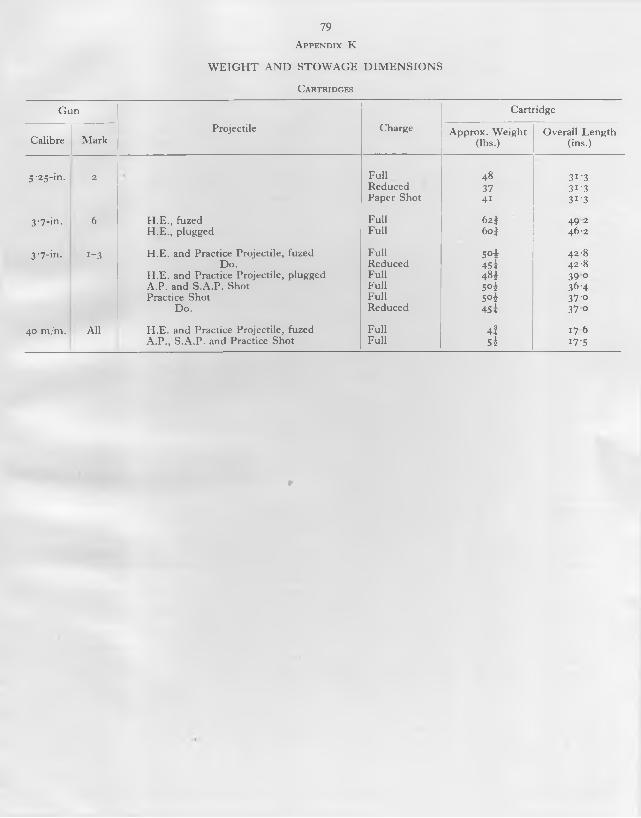
79A p p e n d i x K
W E IG H T A N D S T O W A G E D IM E N S IO N S
C a rtrid ges
G un
Projectile Charge
Cartridge
Calibre M arkA pprox. W eight
(lbs.)O verall Length
(ins.)
5 '25 -in . 2 Fu ll 48 3 t '3Reduced 37 3 f 3Paper Shot 41 3 1 '3
3 -7-in. 6 H .E ., fuzed Full 6 2 } 4 9 2H .E ., plugged Fu ll 6 0J 46-2
3 -7-in. 1 -3 H .E . and Practice Projectile, fuzed Fu ll 5 ° i 42-8Do. Reduced 45 i 42-8
H .E . and Practice Projectile, plugged Fu ll 4 « i 3 9 °A .P . and S .A .P . Shot Fu ll 5 ° 4 3 6 '4Practice Shot Fu ll 5 ° 4 37-0
Do. Reduced 45 i 37 0
40 m/m. All H .E . and Practice Projectile, fuzed Full 4 f 1 7 6A .P ., S .A .P . and Practice Shot Fu ll 54 i 7 '5
r
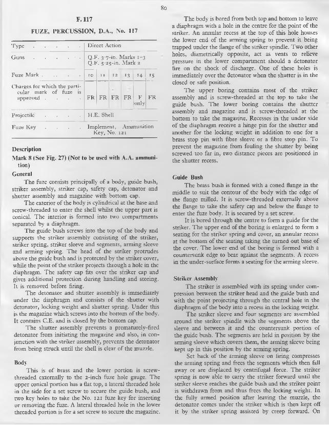
8o
F. 117
FUZE, PERCUSSION, D.A., No. 117
T y p e ....................................... D irect Action
G uns . . . . • . Q .F . 3 7-in. M arks 1 - 3 Q .F . 5 25-in . M ark 2
Fuze M a r k ................................ IO I I 1 2 1 3 1 4 IS
Charges for w hich the particular m ark o f fuze is approved . . . . F R F R F R F R F
onlyF R
Projectile . . . . H .E . Shell
Fuze K e y . . . . Im plem ent, Am m unitionK e y , N o. 1 2 1
DescriptionMark 8 (See Fig. 27) (Not to be used with A.A. ammuni
tion)General
The fuze consists principally of a body, guide bush, striker assembly, striker cap, safety cap, detonator and shutter assembly and magazine with bottom cap.
The exterior of the body is cylindrical at the base and screw-threaded to enter the shell whilst the upper part is conical. The interior is formed into two compartments separated by a diaphragm.
The guide bush screws into the top o f the body and supports the striker assembly consisting o f the striker, striker spring, striker sleeve and segments, arming sleeve and arming spring. The head o f the striker protrudes above the guide bush and is protected by the striker cover, while the point o f the striker projects through a hole in the diaphragm. The safety cap fits over the striker cap and gives additional protection during handling and storing. It is removed before firing.
The detonator and shutter assembly is immediately under the diaphragm and consists of the shutter with detonator, locking weight and shutter spring. Under this is the magazine which screws into the bottom o f the body. It contains C.E. and is closed by the bottom cap.
The shutter assembly prevents a prematurely-fired detonator from initiating the magazine and also, in conjunction with the striker assembly, prevents the detonator from being struck until the shell is clear o f the muzzle.
BodyThis is of brass and the lower portion is screw-
threaded externally to the 2-inch fuze hole gauge. The upper conical portion has a flat top, a lateral threaded hole in the side for a set screw to secure the guide bush, and two key holes to take the No. 12 1 fuze key for inserting or removing the fuze. A lateral threaded hole in the lower threaded portion is for a set screw to secure the magazine.
The body is bored from both top and bottom to leave a diaphragm with a hole in the centre for the point of the striker. An annular recess at the top of this hole houses the lower end of the arming spring to prevent it being trapped under the flange o f the striker spindle. Two other holes, diametrically opposite, act as vents to relieve pressure in the lower compartment should a detonator fire on the shock of discharge. One of these holes is immediately over the detonator when the shutter is in the closed or safe position.
The upper boring contains most o f the striker assembly and is screw-threaded at the top to take the guide bush. The lower boring contains the shutter assembly and magazine and is screw-threaded at the bottom to take the magazine. Recesses in the under side o f the diaphragm receive a hinge pin for the shutter and another for the locking weight in addition to one for a brass stop pin with fibre sleeve or a fibre stop pin. To prevent the magazine from fouling the shutter by being screwed too far in, two distance pieces are positioned in the shutter recess.
Guide BushThe brass bush is formed with a coned flange in the
middle to suit the contour of the body with the edge of the flange milled. It is screw-threaded externally above the flange to take the safety cap and below the flange to enter the fuze body. It is secured by a set screw.
It is bored through the centre to form a guide for the striker. The upper end of the boring is enlarged to form a seating for the striker spring and cover, an annular recess at the bottom of the seating taking the turned out base of the cover. The lower end of the boring is formed with a countersunk edge to bear against the segments. A recess in the under-surface forms a seating for the arming sleeve.
Striker AssemblyThe striker is assembled with its spring under com
pression between the striker head and the guide bush and with the point projecting through the central hole in the diaphragm of the body into a recess in the locking weight.
The striker sleeve and four segments are assembled around the striker spindle with the segments above the sleeve and between it and the countersunk portion of the guide bush. The segments are held in position by the arming sleeve which covers them, the arming sleeve being kept up in this position by the arming spring.
Set back of the arming sleeve on firing compresses the arming spring and frees the segments which then fall away or are displaced by centrifugal force. The striker spring is now able to carry the striker forward until the striker sleeve reaches the guide bush and the striker point is withdrawn from and thus frees the locking weight. In the fully armed position after leaving the muzzle, the detonator comes under the striker which is then kept off it by the striker spring assisted by creep forward. On

8i
impact, the striker cover is crushed and the striker driven down on to the detonator.
StrikerThe aluminium alloy striker has a separate mush
room shaped head secured by a split pin.The striker spindle is circular in section, having a
point at its lower end, above which is a flange to take the lower end o f the striker sleeve. The upper end is reduced in diameter to fit the head and bored to take the split pin.
The striker head is bored centrally to fit the striker and radially for the split pin.
When assembled with the sleeve and segments, there is a small clearance between the bottom of the flange and the seating for the arming spring in the body diaphragm. This is to allow the striker to set back slightly on firing to relieve the pressure on the segments and allow them to fall away.
Striker SpringThis is a spiral o f circular section steel wire and is
assembled under initial compression between the striker head and the upper face o f the guide bush. When the striker is released by the falling away o f the segments, the spring carries the striker forward to withdraw the point from the recess in the locking weight.
Striker SleeveThis cylindrical steel sleeve fits over the striker
spindle, bearing against the upper face o f the flange on the striker. The upper end is chamfered to bear against the lower countersunk edge of the segments.
SegmentsThe four brass segments together form a hollow
cylinder around the striker spindle. The upper edges of the segments are chamfered whilst the lower edges are countersunk, viewing the segments as a cylinder. They are assembled between the guide bush and striker sleeve and keep the striker spring under compression until released by set back and centrifugal force, thus keeping the point o f the striker in the recess in the locking weight.
Arming SleeveThis is a hollow brass cylinder with the upper and
lower edges turned over to form bearing surfaces fot the arming spring and guide bush. The arming sleeve is assembled over the segments and above the arming spring which keeps it up in position until it is forced down by set back on firing.
Arming SpringThis is a spiral o f circular section steel wire and is
assembled over the striker sleeve between the arming sleeve and the bottom o f the recess in the upper surface of the body diaphragm.
Set back of the arming sleeve on acceleration compresses the spring. After the segments have fallen away and acceleration has ceased at the muzzle, the spring reasserts itself and restores the sleeve to its original position.
Striker CoverThis brass dome-shaped cover fits over the striker
head and is secured by the bottom ridged edge being sprung into an annular groove at the base o f the upper recess of the guide bush.
The cover prevents air resistance during flight from acting on the striker head to cause premature action of the striker.
The cover must not be removed when preparing the fu ze fo r loading. The words “ DO N O T R EM O V E” are embossed on the top.
Safety CapThis black-painted steel dome-shaped cap has a flat
steel spring riveted into an oblique slot in the side. The free end of the spring engages on the milling on the guide bush and retains the cap in position. The cap has a milled ring around its circumference and is screw-threaded internally at the lower end for attachment to the guide bush.
The cap must be removed before firing, but N O T the striker cover underneath (q.v.). Up to the end o f 1942, a warning label, L .19 14 , was attached to the safety cap and read as follows:
IM PO RTA N T
WHEN PR EPA R IN G T H IS FU Z E FO R F IR IN G T H E B L A C K S T E E L S A F E T Y CAP O N LY IS
TO BE U N SC REW ED AND REM O VED
Detonator and Shutter AssemblyThis consists of the shutter with detonator, locking
weight and shutter spring. It is assembled under the body diaphragm and above the magazine.
Both the shutter and locking weight are designed to be rotated by centrifugal force about their hinge pins on the underside of the body diaphragm. The detonator is carried on one arm of the shutter and the striker recess is on the free end of the locking weight.
In the safe position the locking weight is under the striker and the detonator is displaced from both the striker and the channel to the magazine. The shutter is prevented from opening by a toe on the locking weight engaging a recess in the side o f the shutter while the locking weight is kept in position both by the shutter spring and by the striker point engaging the top recess.
On release o f the striker, the locking weight is freed and as soon as set back ceases on deceleration after leaving the muzzle, it swings out under centrifugal force. In doing so, its toe starts the shutter turning towards the armed position. It then continues to turn gently under centrifugal force until it comes up against the stop pin with the

82
detonator under the striker. The gentle rotation of the shutter is designed to avoid any shock to the detonator and the stop pin is of fibre or fibre covered for the same reason.
ShutterThe shutter which may be of brass or mazak with a
brass inset, is bored through its centre for its hinge pin and has a recess in the top of one end for the detonator. The other end is enlarged to form a weight to operate under centrifugal force.
A recess machined in the side forms a working surface for the toe o f the locking weight which locks it at rest and starts it rotating to the armed position on leaving the muzzle.
The shutter is designed to open gently when the shell is spun between 1800 and 2200 revolutions a minute.
DetonatorThis consists of a copper alloy shell containing two
grains of detonating composition and three grains of lead azide, all retained by a brass disc and brass washer, secured by turning over five tabs on the shell. It is placed in its recess in the shutter, followed by a glazeboard washer and a brass washer, the whole being retained by spinning over the edge of the recess.
Locking WeightThis is an arc-shaped fitment of brass or mazak
located above the magazine and below the body diaphragm. It is forked at one end to receive the shutter spring and bored vertically for the hinge pin. The other end is formed with a toe, which is machined to act as a working surface in the recess in the side of the shutter. The upper surface of the toe is recessed to take the point o f the striker.
In the safe position the shutter spring keeps the toe engaging the recess in the side of the shutter and assists in preventing it opening. The striker point is also in the recess in the top of the locking weight and thus prevents the shutter opening whilst the fuze is at rest and until acceleration has ceased in the gun.
Shutter SpringThis is a spiral steel spring with two free ends. It is
assembled on the hinge pin of the locking weight, one end bearing against the edge o f the fuze body recess and the other engaging the forked end o f the locking weight.
It keeps the toe of the locking weight engaged in the recess in the side of the shutter until overcome by centrifugal force, acting on both locking weight and shutter.
MagazineThis is of brass or mazak. The main upper portion is
screw-threaded externally to suit the body whilst the
bottom part is reduced in diameter for the bottom cap. It is secured in the body by a set screw at the side.
The magazine is bored from the base in two diameters, the larger bore containing a C.E. pellet which is assembled with the hard end nearest to the bottom cap, a paper disc being shellacked to the top surface. The smaller bore terminates in a diaphragm from 0-003 10 0-008 o f an inch thick and is filled with stemmed C.E.
Bottom CapThis may be of brass, aluminium alloy or steel and is
screw-threaded internally to suit the magazine. It screws over the bottom of the magazine and retains the C.E. pellet. After filling the cap is crimped in two or more places to prevent it unscrewing.Mark 15 (not illustrated)
This is similar to the Mark 8 except that:The striker and striker head are o f steel.The striker cover is thicker and the striker head
is o f smaller diameter.
Mark 14 (not illustrated) (NOT to be used with reduced charge)
This is the same as the Mark 8 except for a thicker striker cover and smaller diameter striker head.
Mark 13 (not illustrated)This differs from the Mark 8 in the following
respects:Thicker striker cover and smaller diameter
striker head.Steel striker, striker head, guide bush, magazine
and body.
Mark 12 (not illustrated)This differs from the Mark 8 in the following respects:
Thicker striker cover and smaller diameterstriker head.
Steel striker and striker head.Only one distance piece in the magazine recess.
Mark 11 (not illustrated)This differs from the Mark 8 in the following respects:
Thicker striker cover and smaller diameter striker head.
Steel striker and striker head.Only one distance piece in the magazine recess. Shutter of brass only and of a slightly different
design.
Mark 10 (not illustrated)This differs from the Mark 8 in the following respects:
Thicker striker cover and smaller diameter striker head.
Steel striker and striker head.
Mark 4 (not illustrated) (NOT to be used with A.A. ammunition)
This is the same as the Mark 8 except that the striker, striker head, guide bush, magazine and body are o f steel.

Mark 3A (not illustrated) (NOT to be used with A.A. ammunition)
This is the same as the Mark 8 except that the striker and striker head are made o f steel.
Mark 3 (not illustrated) (NOT to be used with A.A. ammunition)
This differs from the Mark 8 in the following respects: Striker and striker head of steel.A single distance piece in the magazine recess.
Mark 2 (not illustrated) (NOT to be used with A.A. ammunition)
This differs from the Mark 8 in the following respects: Steel striker and striker head.Only one distance piece in the magazine recess. Shutter o f brass only and of a slightly different
design.
Action On Firing
The arming sleeve sets back and compressing the arming spring, uncovers the segments. This movement, combined with a slight set-back of the striker, releases
the segments which either fall clear or are displaced by centrifugal force.
On leaving the BoreThe striker spring reasserts itself and forces the
striker and striker sleeve forward until the sleeve meets the guide bush and the striker point is withdrawn from the locking weight. This allows the locking weight to revolve by centrifugal force and in doing so its toe starts to turn the shutter into the armed position. The shutter continues to revolve gently by centrifugal force until it reaches the stop pin and the detonator comes under the striker.
The striker is now fully armed, the striker point being held clear o f the detonator by the striker spring assisted by creep forward.
On ImpactThe striker cover is forced on to the striker head and
the striker forced down for its point to pierce the detonator. The resulting detonating wave passes through the magazine diaphragm to the C .E . in the magazine channel and magazine.

84F. 208
F U Z E , T IM E , No. 208Particulars
T y p e M echanical, T h ie l M ovem ent
T im e o f Running . 43 seconds m axim um
Fuze M ark 1 2 3 4 5 6
G u n s for w hich the particular m ark o f fuze is approved
3 '7-in . M ks. 1 to 3 3-7-in. M k. 6 (Fuzes
made b y R .O .F . (B) only
S-25-in . M k. 2
3 -7-in. M k . 6
Projectiles H .E . shell and practice projectiles
FuzeK eys
Inserting and Rem oving
Im plem ents, Am m unition, K e y s N o. 223 and 175
Setting . Im plem ents, Am m unition, K e y N o. 140
Description
M ark 3 (see Fig. 19)
GeneralThe fuze consists o f a body containing a clockwork
mechanism (“ Clock” ) or movement with striker, detonator, shutter and magazine and covered by a dome and cap.
The exterior of the body is threaded at the bottom to screw into the nose o f the shell, a copper and asbestos washer being put between fuze and shell to make a gas- tight joint.
The top o f the body is enlarged and shaped to conform to the shell contour, this contour being maintained by the top part of the dome and the cap fixed on top of it.
The interior o f the body is divided by a platform. The upper part contains the movement, a recess in the underside o f the platform takes the detonator, and the bottom part contains the shutter and magazine.
The dome covers the top of the clock and can be rotated in the fuze body. The dome is retained by a screwed collar which bears down on to a spring tensioning ring over a flange at the foot of the dome. Adjustment of the screwed collar varies the stiffness or “ tension” of the fuze.
Inside the dome at the top is a locking weight. Setback of the weight on firing drives in locking pins to jam the dome to the body and lock the dome as set. Beneath the locking weight is a platform or hand race, across which a shaped slot is cut. Rotation of the dome positions the slot and thereby sets the fuze.
The mechanism rotates a spring-loaded hand beneath the hand race.
The clock is driven by a mainspring and controlled by an escapement through a train of gear wheels.
The movement is started by the firing of the gun, the hand being released for rotation by the set-back of a
trigger. A muzzle safety bridge prevents the hand from rising until 0 7 2 seconds after firing. Thereafter the hand bears on the under surface of the hand race until, at the end o f the time as set, it has rotated until it is coincident with the slot in the hand race into which it rises.
The hand is mounted on a hollow hand centre, the rim of which engages a tip on the end of a lever fixed to the top of the striker. A cam on the striker rests on a pillar and the rising o'f the hand releases the lever which allows a striker spring to rotate the cam off the pillar and force the striker down on to the detonator and thus initiate the magazine. The striker is prevented from reaching the detonator before the shell leaves the muzzle by a centrifugal safety catch.
A shear wire between the body and dome prevents the dome being moved accidentally before loading; the tensioning ring prevents accidental movement of the dome during loading; the shutter stops a prematurely fired detonator from initiating the magazine; the trigger prevents the hand rotating until the gun is fired; the centrifugal safety catch stops the striker reaching the detonator before the shell reaches the muzzle and the muzzle safety bridge prevents the hand rising until the shell is well clear of the muzzle.
BodyThis is of brass, the lower part being cylindrical and
the upper part enlarged over a flange and coned at a radius o f eight calibres when measured in conjunction with the shell for the 3'7-in. Mks. 1 to 3 guns.
The lower half o f the bottom part is plain and the upper half is screw-threaded to the 2-in. fuze hole gauge. On the plain portion is a hole for a set-screw for fixing a magazine securing ring. In the threaded portion is a radial hole, closed by a plug, to give access to a regulator screw in the clock, and above this, three equidistant holes for screws to hold the movement to the body.
Under the flange is a small oblique hole for a grub screw to secure the screwed collar.
At the bottom of the upper coned part of the body is a small recess to take the stud o f the No. 223 fuze key and there are also two grooves diametrically opposite for the No. 175 fuze key. Either key can be used for inserting or removing the fuze. (The recess was introduced in 1945 and the grooves will be omitted in future manufacture.)
Two recesses near the bottom are to take the spring- loaded plungers of pawl type fuze keys (e.g. No. 140) for setting the fuze.
At the bottom is a radial hole for a shear wire, the inner end of the wire engaging a recess in the flange o f the dome when the fuze is set to SA FE on assembly.
The top of the coned surface is graduated for nearly the whole circumference in quarter divisions from f to 28I, each whole division or “ fuze length” being numbered from 1 to 28. A safety mark filled in with red paint and with the word SA F E engraved below, is on the ungraduated portion.
85
The interior o f the upper part of the body forms a bearing for the dome and is screw-threaded to take the screwed collar to secure it.
The internal platform is formed by recessing from both top and bottom. The clock rests on top of the platform, being positioned from underneath by two dowel pins nearly diametrically opposite, and secured by three equidistant screws inserted from underneath.
Near the circumference of the platform is a hole for a detonator holder and underneath an eccentric counterbore for the flange o f the holder with two screw holes for fixing it.
The bottom part of the body contains the magazine which is positioned by two dowel pins to the body platform. It is screw-threaded internally to take the magazine securing ring.
Movement(see Fig. 20)
The clock is assembled as a complete unit and fixed to the top of the platform in the fuze body.
A detailed description is given under “ Mechanism, Time, 43 seconds” .
DomeThe aluminium alloy dome is cylindrical in shape
with a flange at the base to take the tensioning ring. The top part is coned to conform to the fuze contour.
A small recess in the side of the flange registers with a radial hole in the fuze body when the fuze is set to SA FE. During assembly the shear wire is inserted to lock the dome at SA FE. It is sheared on setting the fuze. (This feature was not introduced until late 1946.)
The dome is assembled on a washer inserted on the bearing surface inside the enlarged upper portion of the fuze body. It is held in position by the screwed collar.
On the coned portion are two recesses for the spring- loaded plungers of pawl type fuze keys. A vertical indicating line is engraved for reading the fuze setting and the fuze number (208) and mark, manufacturer’s initials and date of manufacture are stamped on the other side. At a slightly higher level and to one side is stamped the mechanism number.
The interior of the dome is recessed from both top and bottom to form a platform and hand race near the lower end. The lower and smaller recess covers the top of the clock and the upper recess houses the locking weight.
The lower surface of the platform forms a race-way for the hand of the clock and a diagonal slot shaped as a silhouette of the hand allows the hand to pass through at the end of the time as set. A small hole through the hand- race gives access to the trigger for arming it when testing.
Above the hand-race is the locking weight consisting o f one large disc with three smaller ones fixed to it underneath by four screws. The large disc is fixed by three copper shearing pins to the wall of the dome. The small discs project partly beyond the edge o f the large disc and
the projecting portions are accommodated in slots cut in the inside wall o f the dome. Vertical holes from each of these slots to the bottom of the dome take three locking pins. On firing, the shearing pins are sheared as the locking weight sets back on to the locking pins and drives them downwards. The pointed ends of the pins are thus wedged between the dome and recesses in the body, locking dome and body firmly together. This action prevents any alteration o f fuze setting after firing.
The top o f the dome is screw-threaded internally to take the cap and a small hole in the side takes a set-screw to secure it.
Screwed CollarThis cylindrical brass sleeve is threaded on the outside
to engage the threads on the inside o f the fuze body. The top is coned to conform to the fuze contour and four equidistant slots in the coned portion are for a tool used for assembly and for adjusting the collar.
The collar is assembled round the dome and screwed down on to corrugated steel spring wire tensioning ring above the flange at the base of the dome. Adjustment of the collar varies the pressure of the dome on the body. This pressure or “ tension” is adjusted during assembly to resist a torque o f about 325 inch-ounces which is sufficient to prevent movement o f the dome during loading. After the tensioning has been done the screwed collar is fixed by a grub screw inserted from the under-side of the body flange.
CapThis ballistic cap of aluminium alloy or plastic
material is screwed into the upper end of the dome and secured by a set-screw. Two holes diametrically opposite are for an assembly tool. (They should not be used for inserting or removing the fuze.)
Detonator HolderThis cylindrical brass holder has an eccentric flange
at the base for two fixing screws. Internally the top is recessed to take the detonator and below this is bored to form a small fire channel.
It is inserted in the platform from underneath with the detonator immediately beneath the striker.
DetonatorThis consists of a copper shell containing three grains
of lead azide topped with two grains of D.C. “ A ” mixture. The filling is covered and pressed in by a brass washer and disc and secured by turning over lugs on the top of the shell.
MagazineThis is o f brass and is screw-threaded externally at
the bottom to take a bottom cap. It is bored from the underside to form a chamber to take a C.E. pellet, the pellet being held in by the bottom cap over a cloth washer.

86
A collar is formed towards the top of the magazine, the under-surface of which forms a bearing for the magazine securing ring. The top forms a platform for the shutter assembly.
A diagonal slot across the top accommodates the sliding shutter. Two dowel pins in recesses form pivots for the shutter springs and position the magazine to the fuze body platform.
A small channel, off centre, with a diaphragm left at the top, leads from the shutter slot to the chamber. It is filled with stemmed C.E.
The magazine is held in position by the magazine securing ring.
Bottom Cap
This may be of brass, aluminium alloy or steel, and is screw-threaded internally to suit the magazine. It screws over the bottom o f the magazine and retains the C.E. pellet. After filling the magazine, the cap is crimped in two or more places to prevent it unscrewing.
Shutter
The brass shutter slides in the shutter slot on the top o f the magazine.
At one end is a diagonal channel filled with C.E. Small holes in the sides of a recess at the other end of the shutter take the ends of the two steel shutter springs which pivot on dowel pins and keep the shutter at the centre in the closed or safe position. In this position the diagonal channel is clear o f both the detonator and magazine channels and the detonator is blocked by the solid part of the shutter.
When the shell is in flight and the speed of rotation of the shell exceeds 4,500 r.p.m., centrifugal force overcomes the springs and pulls the shutter outwards to the open or armed position. In this position the detonator, shutter channel and magazine channel are all in line.
Magazine Securing Ring
This is a brass collar screw-threaded on the outside to enter the fuze body from underneath. It surrounds the magazine and secures it by bearing on the under-surface o f the collar formed on the upper part of the magazine. The ring is secured by a set-screw inserted from the side of the plain portion on the bottom of the fuze body. Four slots at the bottom are for an assembly tool.
M ark 1 (not illustrated)
This is similar to the Mark 3, except that the pivots o f the third, fourth and ’scape wheels are o f smaller diameter. The pinions are also smaller and the gear ratio consequently slightly different.
There is no hole in the fuze body to take No. 223 fuzekey.
M arks 2 and 4These marks were allotted for fuzes identical to the
Marks 1 and 3 fuzes respectively, except that the body and certain other components were to have been made of steel instead of brass. They were never put into production.
M ark 5 (not illustrated)The fuze body is identical with the Mark 3, the only
difference being in the fitting of the No. 3 mechanism with Duralumin third, fourth and ’scape wheels instead of brass. This mechanism is specifically regulated to suit the ballistics of the 3'7-in. Mk. 6 gun.
M ark 6 (not illustrated)The fuze body is identical with the Mark 3, the only
difference being in the fitting of the No. 4 mechanism which has brass third, fourth and ’scape wheels as foi the No. 2 mechanism in the Mark 3 fuze, but is fitted with a wider and stronger mainspring. The mechanism is specifically regulated for the ballistics of the 3'7-in. Mk. 6 gun.
ActionBefore Firing
The setting o f the fuze rotates the dome and thus positions the hand-race slot. In rotating the dome the shear wire is broken.
On FiringThe locking weight sets back, shearing the shearing
pins and driving the locking pins downwards to lock the dome to the body and thus prevent any alteration of fuze setting.
The trigger sets back and frees the hand rotationally.
On leaving the BoreThe clock starts and the hand begins to rotate.The centrifugal safety catch flies outwards to leave
the striker supported only by its cam resting on the pillar.The shutter slides outwards to bring the fire channel
in line with both detonator and magazine channels.When the shell is well clear o f the muzzle, 0 7 2
seconds after bring, the hand clears the muzzle safety bridge and bears on the lower surface o f the hand-race.
At the end of the Time as SetThe hand reaches the hand-race slot into which it
rises. This releases the lever which allows the striker spring to force the cam off the pillar and the striker down on to the detonator. The resulting detonating wave passes through the C.E. in the shutter, the diaphragm above the magazine channel and the C.E. in the magazine channel and initiates the magazine and thus the main shell filling.
Safety ArrangementsShear Wire .
With the shear wire intact and in position as issued, accidental movement of the dome away from SA FE is

87
prevented during transport and handling. It also ensures that the fuze is set accurately at SAFE.
Tensioning RingThis prevents accidental movement of the dome after
setting the fuze, either during loading or subsequent handling or transport.
ShutterThis prevents a prematurely fired detonator from
initiating the magazine and main shell fillings. A detonator so fired before the shell is loaded into the gun would result in a blind.
TriggerThis prevents the hand rotating and the clock starting
until the gun is fired.
Centrifugal Safety CatchThis stops the striker reaching the detonator should
the striker cam be prematurely rotated off the pillar through a breakage of the clock or firing mechanism.
Muzzle Safety BridgeThis prevents the hand rising until 0-72 seconds after
firing, by which time the shell is well clear o f the muzzle. This device operates i f the fuze is set too short.
88
F. 208M
MECHANISM, TIME, 43 SECONDS
Particulars
M echanism N o. • — 2 3 4
Fuze, T im e, N o. 208, M ark
1 and 2 3 and 4 5 6
G uns for w hich approved
3 '7 - in . M ks. 1 to 3 3 '7 - in . M k. 6 3 '7-in . M k. 6 M echs
made by R .O .F .(B )only
5 25-in . M k. 2
M inim um time of functioning
0 72 seconds
M axim um time of running
43 seconds
T yp e Thiel
Description
No. 2 Mechanism (See Figs. 19 and 21)
GeneralInside the dome of the fuze is a platform or hand-race,
across which a shaped slot is cut. Rotation o f the dome positions the slot and thereby sets the fuze.
The mechanism rotates a spring-loaded hand beneath the hand-race.
The mechanism is driven by a mainspring and controlled by an escapement through a train o f gear wheels.
The movement is started by the firing of the gun, the hand being released for rotation by the set-back of a trigger. A muzzle safety bridge prevents the hand from rising until 0-72 seconds after firing. Thereafter the hand bears on the under-surface o f the hand-race until, at the end of the time as set, it has rotated until it is coincident with the slot in the race into which it rises.
The hand is mounted on a hollow hand centre, the rim of which engages a tip on the end of a lever fixed to the top o f the striker. A cam on the striker rests on a pillar and the rising of the hand releases the lever which allows the striker spring to rotate the cam off the pillar and force the striker down on to the detonator. The striker is prevented from reaching the detonator before the shell leaves the muzzle by a centrifugal safety catch.
Mechanism, Movement or “Clock”This comprises the mainspring, gear train and
escapement, the hand and trigger assembly and the firing mechanism.
It is assembled as a complete unit on a frame consisting of bottom, train, barrel and top plates and is fixed on to a platform in the fuze body.
DriveThe drive is by the mainspring coiled inside a barrel
mounted on a centre arbor. One end o f the spring is fixed to the barrel and the other to the arbor. The arbor is held by the hand until the gun is fired and the spring is wound up by rotation of the barrel and retained in that state by a click.
MainspringThe flat steel mainspring is coiled inside the barrel,
the inner end having a slot for engagement on a hook formed on the centre arbor, and the outer end itself forming a hook to engage a catch on the barrel.
BarrelThe brass barrel is mounted on the centre arbor and
has teeth formed on the periphery for engagement with a winding key and the click.
A portion o f the inner circumference is undercut to form a catch for the outer end of the mainspring.
A slot is cut in the bottom to give access and the top is covered by a circular plate.
Click and Click SpringThe steel click pivots on a pin in the barrel plate.It has a single tooth to engage the teeth on the peri
phery o f the barrel to prevent the mainspring from unwinding.
The flat steel click spring is secured to the periphery of the top plate by a screw. The spring keeps the click forced inwards.
Gear TrainThis consists of a sequence o f gear wheels to give the
required step-up ratio from the drive to the escapement.Rotation of the centre arbor by the mainspring turns
the hand at the top and the centre wheel at the bottom. The centre wheel causes the third, fourth and ’scape pinions and wheels to rotate, the steel pinions being mounted above the brass wheels in pairs on the same arbors.
Centre ArborThe cylindrical steel arbor is reduced in diameter at
the bottom to form a pivot which rotates in a bearing hole in the train plate. The arbor passes through a hole in the barrel plate and the top rotates in a bearing hole in the top plate.
It is formed with a flange at its lower end to which the centre wheel is secured by three screws. Above this is another flange, part o f which is undercut to form a hook for engaging the slot on the inner end of the mainspring.
Above this again, the centre arbor is reduced in diameter to suit the central pivot hole in the top plate and again at the top it is reduced to suit the hand centre.
8 9
Centre WheelThe centre wheel is assembled on the lower end of
the centre arbor with three securing screws. It is housed in a recess in the upper surface o f the train plate and drives the third pinion.
3rd. Arbor, Pinion and WheelThe arbor pivots rotate in bearing holes in the
bottom and train plates.The pinion enters a recess in the train plate and is
driven by the centre wheel.The wheel drives the fourth pinion.
4th. Arbor, Pinion and WheelThe arbor pivots rotate in bearings in the bottom
and train plates.The pinion is driven by the third wheel and the wheel
drives the ’scape pinion.
Escapement(see Fig. 21)
This comprises the escape wheel, pallet and hairspring and is the controlling device by means o f which the power o f the drive is allowed to “ escape” only at a steady rate.
Vibration of the hairspring and pallet disengages one of the pads from the ’scape wheel. In doing so, the pad receives an impulse from the ’scape tooth as it jumps forward before being eventually locked by the entry o f the other pallet pad into an adjacent tooth. This action is repeated by the disengagement o f the second pad.
The resulting series of impulses is transmitted to the pallet arm and results in an oscillation which is maintained at a rate determined by the weight and length of the pallet arm and the effective length and bending properties o f the hairspring.
Escape Arbor, Pinion and WheelThe arbor pivots rotate in bearings in the bottom and
train plates.The pinion is driven by the fourth wheel.The brass ’scape wheel has specially shaped teeth for
engagement by the pallet pads.
PalletThe pallet consists of a straight steel bar, termed the
pallet arm, with a hole in the centre for riveting to a steel arbor. On each end o f the arm is a circular brass weight and at the centre, and at right angles to it, are two short arms with the ends turned upwards. The ends o f the short arms are termed pallet pads and -alternatively engage successive teeth o f the ’scape wheel.
The arbor has a radial hole to take the hairspring. The pivots of the arbor rotate in bearing holes in the centre o f the bottom plate and in a cover plate below the bottom plate.
Hairspring and RegulatorThe centre of the straight phosphor-bronze hair
spring is fitted between two D-shaped copper strips secured in the radial hole in the pallet arbor. The ends of the spring are held loosely in saw-cuts in the bottom plate and the regulator.
The regulator is a metal block which slides in an undercut groove in the bottom plate where it is held by a regulator screw. The regulator screw has a flange which engages a slot in the regulator. Movement of the screw in the tapped hole in the bottom plate slides the regulator in or out and thus alters the effective length o f the hairspring.
Hand and Trigger AssemblyThis consists o f the hand, hand centre and hand
spring, trigger, trigger locking strip and trigger locking bolt and a muzzle safety bridge.
The hand is secured to the hand centre and the latter fits loosely on the top o f the centre arbor. The hand centre compresses the spiral handspring inside the arbor and also contains the end of the lever. The hand and hand centre are thus tending to be rotated by the centre arbor and pushed up by the handspring.
The trigger prevents the hand rotating, and the trigger locking strip prevents it rising until the gun is fired, when the trigger, together with the locking strip, sets back to release the hand. The trigger locking bolt locks the trigger in the set-back position.
The hand is now free to rotate but is still prevented from rising by the muzzle safety bridge until the shell is well clear o f the muzzle. After clearing the bridge, the hand then bears on the under surface of the hand race.
At the end of the time as set and as determined by the positioning of the hand race slot, the hand and hand centre are forced up through the slot and release the lever to operate the striker.
HandThe aluminium hand fits around the hand centre to
which it is secured by screws. It has two arms, the longer bevelled one being grooved at the rear edge for the trigger locking strip to engage and retain in the down position.
Hand CentreThe steel hand centre comprises an inner and outer
cylinder connected by a bridge piece. The cylinders fit loosely over the hollow end o f the centre arbor, one inside and one outside, with the bridge piece resting in slots in the top of the arbor.
A flange on the inside o f the inner cylinder forms a bearing for the top of the handspring.
The outer cylinder retains the tumed-up end o f the lever until it is released by the rising of the hand and hand centre.

9 0
HandspringThe spiral steel handspring is housed in the centre
arbor and inner cylinder of the hand centre. It is held in compression between the bottom of the centre arbor recess and the flange o f the inner cylinder of the hand centre until the latter is free to rise.
TriggerThe brass trigger works in a slot in the top plate and
pivots about one end on a trigger fulcrum pin also in the top plate. The other end has a projection on top to prevent the hand rotating until the trigger sets back on firing. This projection has a bevelled flange to ride over the hand on set-back.
The inner side of the trigger is chamfered to avoid fouling the barrel.
Trigger Locking StripThis flat brass strip is fixed to the top o f the trigger by
a screw, one end o f the strip having a tab which is bent over to enter a hole in the trigger. The other end engages the groove in the rear edge of the hand to prevent the latter being lifted by its spring until the gun is fired. The trigger sets back on firing and in doing so bends the strip clear o f the groove in the hand.
Trigger Locking BoltThis brass bolt is fitted over a steel spiral spring and
inserted in a recess in the side of the trigger. When the trigger sets back, the bolt is forced partly out o f the recess into a notch in the barrel plate to lock the trigger in the set-back position.
Muzzle Safety BridgeThe brass safety bridge fits across the trigger slot in
the top plate and forms a back stop to the trigger. The lower surface is cut away to clear the trigger locking strip and the top is extended forward over the trigger to cover the hand and prevent it rising until it has rotated an amount equivalent to 0 72 seconds time of running. This ensures that a fuze set too short will not burst the shell anywhere near the muzzle.
Firing MechanismThis consists o f a lever and lever arbor; striker and
striker spring; pillar and centrifugal safety catch.The tumed-up end o f the lever fits inside the hand
centre and the other end is riveted to the top of the lever arbor.
The top of the striker slides in a vertical slot in the lower half of the lever arbor so that lever and striker rotate together.
A cam on the striker rests on the pillar.The rising of the hand centre frees the lever which
then flies outwards as the striker cam is rotated off the pillar and the striker driven down on to the detonator.
The centrifugal safety catch will arrest the striker cam and prevent the striker reaching the detonator should the cam be accidently rotated off the pillar before the gun is fired. Unless this has happened, however, the safety catch swings clear by centrifugal force after firing.
LeverThe steel lever has one end square in section to suit
the upper end o f the lever arbor to which it is riveted. The other end is bent upwards to protrude through the curved slot in the top plate and fit inside the outer cylinder o f the hand centre.
Lever ArborThe top of the cylindrical steel arbor is squared to
suit the lever and is fitted with a brass pivot. The lower part o f the arbor has a vertical slot to take the upper end o f the striker.
The arbor rotates in a bearing hole in the top plate and a recess formed in the upper side o f the barrel plate.
StrikerThe upper end o f the cylindrical steel striker has two
flats to suit the slot in the lever arbor, and the lower end is pointed to pierce the detonator. A flange towards the lower end is shaped to form a cam, the bottom of which is bevelled to facilitate rotation off the pillar when the lever is freed. The cam would also be engaged by the centrifugal safety catch and the striker thus prevented from reaching the detonator should the cam be rotated off the pillar due to any cause, such as a broken lever.
After firing, the downward movement o f the striker is limited by a recess in the top o f the bottom plate.
Striker SpringThis spiral steel spring fits round the striker between
the top o f the cam and the under-side o f the barrel plate.The release o f the lever allows the spring to rotate
the cam off the pillar and force the striker down on to the detonator.
PillarThe steel pillar is fitted on top o f the bottom plate
and is secured by punching. The upper end is rounded to engage the bevel o f the striker cam.
Centrifugal Safety CatchThis consists o f a brass block with a flange on the
inner side. An off-set hole takes a pivot pin on which the catch rotates.
The pivot pin is screwed into the under-side o f the bottom plate and the upper end enters a hole in the train plate.
A spiral steel spring is assembled on the pivot pin, one end fitting in an undercut to a step on the top of the catch and the other bearing against a stop pin fitted on top of the bottom plate.

9 i
Before firing, the spring keeps the safety catch in the safe position with the flange under the striker cam. After firing, centrifugal force overcomes the spring and swings the catch clear.
Should the movement be accidentally set in motion, or the lever break before firing, the striker cam would be rotated off the pillar down on to the flange o f the safety catch and thus prevent the striker reaching the detonator. In this case, the downward pressure o f the striker spring is sufficient to prevent the catch swinging out in flight.
FrameThis is made up o f four brass plates assembled one
above the other and known as the bottom, train, barrel and top plates respectively.
The plates are positioned by dowel pins and secured by screws.
There are two dowel pins between the fuze body and the bottom plate. One o f the dowel pin holes in the bottom plate also takes one end o f a long dowel pin that goes through all four plates. A short dowel pin goes through bottom, train and barrel plates.
Three equidistant screws inserted from the underside o f the fuze body platform secure the bottom plate. The same screwed holes in the bottom plate are used to take the ends o f three holding screws to hold all four plates together.
Three studs screwed in from the outside threaded portion o f the fuze body fit into equidistant holes on the periphery o f the bottom plate.
Holes are also provided in bottom and train plates for a movement screw to hold these plates together and retain the movement during assembly.
Bottom PlateThree small holes form bearings for the lower pivots
o f the third, fourth and ’scape wheels.A hole in the centre forms a bearing for the upper
pivot of the pallet arbor. The lower pivot o f this arbor operates in a bearing hole in a small cover plate positioned on the under-side o f the bottom plate by two dowels and secured by two screws.
A screwed hole takes the head o f the centrifugal safety catch pivot pin and, nearby, two plain holes for the stop pin and pillar and a larger one for the striker to pass through.
A recess in the upper-side o f the plate accommodates the striker cam when in the fired position and thus limits the movement of the striker.
Train PlateThree small holes form bearings for the upper pivots
o f the third, fourth and ’scape wheels, and a large recess below the bearing for the third wheel enables the third pinion to engage the centre wheel situated in a recess in the top o f the plate.
A central hole forms a bearing for the centre arbor pivot.
A small hole is for the centrifugal safety catch pivot pin and, nearby, a larger one for the striker to pass through.
Barrel PlateThe centre o f the plate, on the upper-side, is recessed
to house the barrel and a central hole permits the centre arbor to pass through.
There is a hole for the lower end o f the winding key to pivot in, the hole being enlarged on the upper-side to give clearance for the teeth o f the key.
A hole for the upper end o f the striker to pass through is enlarged on the under-side to form a seating for the striker spring, the upper-side housing the lower end of the lever arbor.
A groove in the upper-side takes the trigger when it sets back, and a V-notch connects with the groove and receives the spring-loaded trigger locking bolt to retain it in the set-back position.
A recess in the upper-side houses the click which pivots on a pin, also in the barrel plate. The side o f the plate has a flat surface to suit the click spring and a notch receives the end of the spring with a hole for the spring securing screw.
Top PlateOne hole forms a bearing for the lever pivot and
another gives access to the click to release it if necessary.The centre is bored for the centre arbor to pass
through and to form its upper bearing, and, nearby, a curved slot permits the bent-up end of the lever to protrude and operate.
A straight slot is cut to house the trigger which pivots on a trigger fulcrum pin screwed into the inner-side of the slot. The holes on either side o f the trigger slot are for screws to fix the muzzle safety bridge.
Mechanism for Fuze 208, Marks 1 and 2 (not illustrated)This is similar to the No. 2 mechanism, except that
the pivots and pinions o f the third, fourth and ’scape wheels are o f smaller diameter and the gear ratios and number of teeth consequently slightly different.
No. 1 Mechanism (not illustrated)This is an 8o-second mechanism for use in fuze,
time and D.A., No. 2 13 , and is not used in anti-aircraft artillery.
No. 3 Mechanism (not illustrated)This is similar to the No. 2 mechanism except that
the third, fourth and ’scape wheels are made of duralumin instead o f brass, to counter the increased pivot friction due to the high rate of spin o f the 3'7-in. Mark 6 gun for which this clock is specifically regulated.
92No. 4 Mechanism (not illustrated)
This is similar to the No. 2 mechanism with brass third, fourth and ’scape wheels, except that the mainspring is wider and stronger to overcome the increased pivot friction due to the high rate of spin o f the 3-7-in. Mark 6 gun for which the clock is also specifically regulated.
ActionBefore Firing
The setting o f the fuze rotates the dome and thus positions the hand-race slot.
On FiringThe trigger sets back until the top projection clears
the hand. In doing so, the trigger locking strip is forced out o f the groove in the hand. The trigger locking bolt is forced outwards by its spring into the V-groove, thus retaining the trigger in the set-back position.
On leaving the BoreThe oscillation of the pallet will start the clock and
the hand will begin to rotate.The centrifugal safety catch flies outwards and leaves
the striker supported only by its cam resting on the pillar.The hand is prevented from rising by the muzzle
safety bridge until 0-72 seconds after firing when the shell is well clear o f the muzzle.
At the end of the Time as SetThe hand has rotated until it reaches the hand-race
slot into which it rises under action o f its spring. This releases the lever which flies outwards as the striker forces the cam off the pillar and the striker down on to the detonator.
Safety Arrangements- Trigger
This prevents the hand rotating and the trigger locking strip prevents it rising until the gun is fired.
Centrifugal Safety CatchShould the movement be accidendy set in motion, or
the lever break before firing, the striker cam would be rotated off the pillar down on to the flange o f the safety catch and thus prevent the striker reaching the detonator. The downward pressure o f the striker spring is sufficient to prevent the catch swinging out in flight.
Muzzle Safety BridgeThis prevents the hand rising until it has rotated an
amount equivalent to 0-72 seconds time of running. This ensures that a fuze set too short will not burst the shell anywhere near the muzzle.
93F. 214
F U Z E , T IM E , No. 214Particular
Type . . . . Mechanical, Junghans Move-
Time o f Runningment
43 seconds maximumGun . . . . Q.F. 3-7-in. Marks 1 to 3Projectile H.E. Shell and Practice Pro-
| Inserting and Fuze Keys Removing
jectileImplement, Ammunition,
Key No. 175 Setting. Implement, Ammunition,
No. 140
Description Mark 1 (see Fig. 19)
GeneralThe fuze consists o f a body containing a clockwork
mechanism or movement with striker, detonator, shutter and magazine and covered by a dome.
The exterior o f the body is threaded at the bottom to screw into the nose o f the shell, a copper and asbestos washer being put between the fuze and shell to make a gas-tight joint.
The top part of the body is enlarged and shaped to conform to the shell contour, this contour being maintained by the upper part of the dome.
The interior of the body is divided by a platform. The upper part contains the movement or “ clock” , a hole in the platform takes the detonator and the bottom part contains the shutter and magazine.
The dome covers the top of the fuze and can be rotated in the fuze body. The dome is retained by a screwed collar which bears down on to a spring tensioning ring over a flange at the foot o f the dome. Adjustment of the screwed collar varies the stiffness or “ tension” o f the fuze.
Inside the dome at the bottom is a platform to which is fixed one end of a hammer spring. The other end is free and has two hammers fixed to it underneath. A setting pin is secured to the dome platform and projects downwards between the hammers. This pin engages a slot in the bent up lug of a timing disc. Rotation o f the dome positions the timing disc and thereby sets the fuze. Set-back o f the hammers on firing flattens the lug of the timing disc and frees it from the setting pin.
The timing disc is fixed to its driving shaft by friction and is rotated by the clock.
The clock is driven by a pair of weighted gear segments actuated by centrifugal force and assisted by two centrifugal springs. It is controlled by an escapement through a train of gear wheels. The movement is released and assisted to start on leaving the muzzle by a centrifugal safety lever acting on the escapement.
The timing disc has a firing slot on its periphery and immediately under the disc is a safety disc which masks the slot at settings below 1-67 seconds.
A centrifugal firing arm has a vertical finger which bears on the periphery o f the timing disc and a pin protrudes radially from its shaft to engage a spring-loaded set-back pin. At the end o f the time as set, the timing disc has rotated until its firing slot reaches the firing arm finger which then slips into the slot. This rotates the firing arm shaft to release a centrifugal striker safety plate which in turn releases the striker and allows it to be driven down by its spring on to the detonator and thus initiate the magazine.
The tensioning ring prevents accidental alteration of the setting before firing; the centrifugal drive ensures that the clock does not run and rotate the timing disc until after the gun has fired; the set-back pin prevents the firing arm rotating until the gun is fired, the shutter stops a prematurely fired detonator from initiating the magazine ; the striker safety plate stops the striker reaching the detonator should the firing arm be rotated before the shell reaches the muzzle; the safety lever locks the escapement and prevents the clock starting until the shell is clear of the muzzle and the safety disc prevents the firing arm rotating until the shell is well clear of the muzzle.
BodyThis is of brass, the lower part being cylindrical and
the upper part enlarged over a flange and coned at a radius o f eight calibres when measured in conjunction with the shell.
The lower half o f the bottom part is plain and the upper half is screw-threaded to the 2-in. fuze hole gauge. On the plain portion is a radial hole for a set-screw to secure a magazine securing ring, and just below the flange are three equidistant holes for movement holding screws to fix the mechanism to the fuze body. Under the flange is a small oblique hole for a grub-screw to secure the screwed collar.
At the base of the upper coned part of the body are two grooves diametrically opposite to take the No. 175 fuze key for inserting or removing the fuze. Two recesses near the bottom are to take the spring-loaded plungers of pawl type fuze keys. Between the grooves on one side is stamped the manufacturer’s initials and date of manufacture and on the opposite side, the lot number.
The top o f the coned surface is graduated for nearly the whole circumference in quarter divisions from o to 28 J, each whole division or “ fuze length” being numbered from o to 28. On the ungraduated portion a safety mark is engraved and filled in with red paint with the word SA FE engraved underneath.
The interior platform is formed by recessing from both top and bottom. The clock rests on top of the platform and is positioned by a movement locating pin and fixed by three equidistant movement screws inserted from

94underneath. Near the circumference of the platform is a screw-threaded hole to take a detonator holder.
The interior o f the upper part o f the body forms a bearing for the dome and is screw-threaded on the inside wall to take the screwed collar to secure it.
The bottom part of the body contains the magazine which is positioned by a long magazine dowel pin to the platform. It is screw-threaded internally for the magazine securing ring.
Movement (see Fig. 20)The clock is assembled as a complete unit and fixed
in the fuze body on top o f the platform.A detailed description of the movement is given under
“ Mechanism, Time, 43 seconds, No. 2 14 Fuze” .
Dome AssemblyThis is in two parts consisting o f a cap and a hammer
spring cup. The hammer spring cup covers the clock and forms a platform to take the hammer spring and setting pin. The hollow cap fits over the hammer spring cup to form a ballistic head.
The bottom o f both the cap and the hammer spring cup is cut away to leave three equally spaced segments, flanged at the base. When assembled together the segments of both components interlock to form a continuous flange to take the tensioning ring.
The dome is assembled on a washer inserted on the bearing surface inside the enlarged upper portion o f the fuze body. It is held in position by the screwed collar.
CapThis hollow-pressed steel cap is cylindrical at the
base and conical at the top. The lower part is cut away to leave three flanged segments. It fits over and interlocks with the hammer spring cup.
On the coned portion are two recesses for the spring- loaded plungers of pawl type fuze keys; a vertical line is engraved for reading the fuze setting and the fuze number (214), manufacturer’s initials and date o f manufacture are stamped on the other side.
Hammer Spring CupThis is of pressed steel and shaped like an inverted
cup. The lower part is cut away at the bottom to leave three flanged segments, a shoulder being formed at the top of the segments to take those parts o f the cap above its cutaway portions.
The top of the hammer spring cup is flat. Two holes near the circumference are for the rivets fixing the hammer spring whilst diametrically opposite is a hole for the setting pin.
Hammer SpringThis is a flat D-shaped steel spring. It is fixed under
the hammer spring cup by two rivets at one end. The
other end has two circular hammers riveted underneath. Set-back o f the hammers on firing flattens the turned-up lug of the timing disc and frees it from the setting pin. The hammer spring subsequently returns to its original position.
Screwed CollarThis cylindrical brass sleeve is threaded on the out
side to engage the threads on the inside of the fuze body. The top part is coned to conform to the fuze contour and four equidistant slots in the coned portion are for a tool used in assembling and adjusting the collar.
The collar is assembled round the dome and screwed down on to the corrugated steel spring wire tensioning ring above the flange at the foot of the dome.
Adjustment of the collar varies the pressure o f the dome on the body. This pressure or “ tension” is adjusted during assembly to resist a torque of about 325 inch- ounces, which is sufficient to prevent accidental movement o f the dome during transport, handling and loading. After the tensioning has been done, the collar is locked by a grub-screw inserted from the under-side o f the body flange.
Detonator HolderThis cylindrical brass holder is screw-threaded
externally to enter the hole in the body platform immediately beneath the striker. Internally, the top is recessed to take the detonator, and below this is a small fire channel. Two recesses underneath and on either side of the fire channel are for an assembly tool.
DetonatorThis consists of a copper alloy shell containing three
grains of lead azide topped with two grains of D.C. “ A ” mixture. The filling is covered and pressed in by a brass washer and disc and secured by turning over the lugs on the top of the shell.
MagazineThis is o f zinc alloy and is screw-threaded externally
at the bottom to take a bottom cap. It is bored from underneath to form a chamber to receive a C.E. pellet, the pellet being held in by the bottom cap over a steel washer.
A collar is formed towards the top of the magazine, the under-surface o f which forms a bearing for the magazine securing ring. The top forms a platform for the shutter assembly.
A diagonal slot across the top accommodates the sliding shutter.
A long magazine dowel pin connects the magazine to the fuze body platform and forms an axis for one of the shutter springs, the other shutter spring pivoting on a short magazine dowel pin that does not enter the platform.

95A small channel, off centre, with a diaphragm left at
the top, leads from the shutter slot to the chamber. It is filled with stemmed C.E.
The magazine is held in position by a magazine securing ring.
Bottom CapThis is of zinc alloy and is screw-threaded internally
to suit the magazine threads. It screws over the bottom of the magazine and retains the C.E. pellet. After filling the magazine, the cap is crimped in two or more places to prevent it unscrewing.
ShutterThe brass shutter slides in the shutter slot on the top
of the magazine. At one end is a diagonal channel filled with C.E. Small holes in the sides o f a recess at the other end of the shutter take the ends of two steel shutter springs which pivot on the magazine dowel pins and keep the shutter at the centre in the closed or safe position. In this position the diagonal channel is clear of both the detonator and magazine and the detonator is blocked by the solid part o f the shutter.
When the shell is in flight and the speed o f rotation exceeds 4,500 r.p.m., centrifugal force overcomes the springs and pulls the shutter outwards to the open or armed position. In this position the detonator, shutter channel and magazine channel are all in line.
Magazine Securing RingThis is a zinc alloy collar screw-threaded on the
outside to enter the fuze body from below. It surrounds the magazine and secures it by bearing on to the underside of the collar on the upper part of the magazine. The ring is secured by a set-screw inserted from the side of the plain portion on the bottom of the fuze or the set-screw may be omitted and the ring secured by stabbing through the set-screw hole. Four slots at the bottom are for an assembly tool.
Alternative Designs (Not allocated distinctive marks)1. Dome Assembly
This consists of a dome and top cap. The dome covers the clock and has an internal platform to carry the hammer spring and setting pin.
DomeThis is an aluminium forging, is cylindrical in shape
with a flange at the foot to take the tensioning ring. The top part is coned to conform to the shell contour, and is screw-threaded internally to take the top cap with a small hole in the side for a set-screw to secure it.
On the coned portion are two recesses for the spring- loaded plungers of pawl type fuze keys; a vertical indicating line is engraved on one side for reading the fuze setting and on the other side is stamped the fuze number (214), manufacturer’s initials and date of manufacture.
The interior of the dome is bored from both top and bottom to leave a ring-shaped platform at the centre. The lower part covers the top o f the clock and the platform has two screwed holes on one side for screws to fasten the hammer spring, and, diametrically opposite, a screwed hole for the setting pin.
The dome is assembled on a washer inserted in the bearing surface inside the enlarged upper portion of the fuze body. It is held in position by the screwed collar.
Top CapThis is a hollow aluminium forging, the base of
which is screw-threaded externally to enter the top of the dome to which it is secured by a set-screw. Two recesses at the base o f the coned portion are for an assembly tool.
Hammer SpringThis is secured to the internal platform in the dome
by two securing screws.
2. Dome AssemblyThis is a single aluminium forging forming a com
bination dome and cap and is similar to the assembled dome and top cap as described above.
3. BodyThis differs from the body already described in that
the internal platform is prepared to take an alternative design o f detonator holder.
Near the circumference of the platform is a plain hole for the centre o f the detonator holder with a small screwed hole on either side for the detonator holding screws, while the under-surface is recessed to take the flange o f the holder.
Detonator HolderThis consists of a cylindrical brass holder with two
opposite flanges at the base for the holding screws. Internally the top is recessed to take the detonator holder and below this is drilled to form a small fire channel.
It is inserted in the body platform from underneath.
Action (Mark 1)Before Firing
, The setting o f the fuze rotates the dome and setting pin and thus positions the timing disc.
On FiringThe hammers set-back and flatten the bent-up lug of
the timing disc and thus free it.The set-back pin drops down through its retaining
spring and ceases to act as a stop to the pin protruding from the shaft of the firing arm and frees the firing arm.
On leaving the BoreThe safety lever o f the escapement rotates centri-
fugally to release and help to start the escapement oscillating.

9 6
The centrifugal gear segments start to drive the clock to keep the escapement going and rotate the timing disc.
The shutter is pulled outwards to bring its fire channel in line with both detonator and magazine channels.
After 1-67 seconds the firing slot o f the timing disc has rotated clear of the safety disc.
At the end of the Time as SetThe timing disc has rotated to bring the firing slot
up to the finger of the firing arm. The finger slips into the slot and in doing so, rotates the firing arm and shaft. This releases the striker safety plate and allows the striker spring to drive the striker down on to the detonator. The resulting detonating wave passes through the C.E. in the shutter, the diaphragm above the magazine channel and the C.E. in the magazine channel and initiates the magazine and main shell fillings.
Safety Arrangements Tensioning Ring
This prevents accidental movement of the dome during transport, handling and loading.
Centrifugal DriveNo energy is available for running the clock and
rotating the timing disc until centrifugal force is created by rotation o f the shell.
Set Back PinThis stops the firing arm rotating before the gun is
fired.
ShutterThis prevents a prematurely fired detonator from
initiating the magazine and main shell filling. A detonator so fired before the shell is loaded into the gun would result in a blind.
Striker Safety PlateThis stops the striker from reaching the detonator
should the firing arm be rotated before the shell reaches the muzzle.
Safety LeverThis locks the escapement and prevents the clock
starting until the shell is clear of the muzzle.
Safety DiscThis prevents the firing arm rotating until 1-67
seconds after firing by which time the shell is well clear of the muzzle. This device operates if the fuze is set too short.
97F .214M
MECHANISM, TIME, 43 SECONDS, No. 214 FUZE
Particulars
G u n ........................................... Q.F. 37-in . Marks 1 to 3
Minimum time of functioning 1-67 seconds
Maximum time of running . 43 seconds
T y p e .................................. Junghans
Description
GeneralInside the dome of the fuze is a platform to which is
fixed one end of a hammer spring. The other end is free and has two hammers fixed to it underneath. A setting pin is secured to the platform and projects downwards between the hammers. This pin engages a slot in the bent- up lug of a timing disc. Rotation of the dome positions the timing disc and thereby sets the fuze. Set-back of the hammers on firing flattens the lug of the timing disc and frees it from the setting pin.
The timing disc is fixed to its driving shaft by friction and is rotated by the mechanism.
The mechanism is driven by a pair o f weighted gear segments actuated by centrifugal force and assisted by two centrifugal springs. It is controlled by an escapement through a train of gear wheels. The movement is released and assisted to start on the shell leaving the muzzle by a centrifugal safety lever on the escapement.
The timing disc has a firing slot on its periphery and immediately under this disc is a safety disc which masks the slot at settings below 1-67 seconds.
A centrifugal firing arm has a vertical finger which bears on the periphery of the timing disc and a pin protruding radially from its shaft to engage a spring-loaded set-back pin.
At the end of the time as set, the timing disc has rotated until its firing slot reaches the firing arm finger which then slips into the slot. This rotates the firing arm shaft to release a centrifugal striker safety plate which in turn frees the striker and allows it to be driven down by its spring on to the detonator.
Mechanism, Movement or “Clock”This comprises the gear segments, gear train and
escapement, the timing disc assembly and the firing mechanism.
It is assembled as a complete unit in a frame consisting of seven plates, numbered 1 to 7 from the bottom, with a pair of spacers between Nos. 6 and 7 plates. It is fixed on to a platform in the fuze body.
DriveThe drive is by centrifugal force acting on the
weighted gear segments and assisted by the centrifugal springs.
The movement is locked by the escapement being held until the shell leaves the muzzle.
Gear Segments and Centrifugal SpringsThere are two similar segments, right and left handed.
Each consists of a flat brass plate, one side of which forms a toothed quadrant. Above the other side o f the plate is fixed a brass D-shaped centrifugal weight. At the true centre of the quadrant is secured a steel centrifugal shaft, the pivots o f which rotate in bearing holes in Nos. 6 and 7 plates.
A steel spiral spring is fitted over each centrifugal shaft with one end bearing against the weight and the other against the inside edge of a spacer.
The segments are mounted on either side of the main driving shaft or centre arbor, the segment teeth engaging a pinion mounted on the arbor.
As soon as the escapement is released, centrifugal force acts on the weights and, aided by the centrifugal springs, rotates the centre arbor and timing disc.
Gear TrainThis consists o f a sequence o f gear wheels to give the
required step-up ratio from the drive to the escapement.The brass wheels are mounted below the teeth o f the
steel pinions in pairs, the ends of the arbors being reduced in diameter at top and bottom to form pivots. The pinions and wheels are numbered from the escapement to the drive, the ’scape pinion being driven by No. 1 wheel.
Rotation o f the centre arbor by the gear segments turns the timing disc at the top and No. 5 wheel at the bottom. This causes Nos. 4, 3, 2, 1 and ’scape pinions and wheels to rotate.
Centre Arbor and No. 5 Pinion and WheelThe cylindrical steel arbor is reduced in diameter at
the bottom to rotate in bearing holes in the centre of Nos. 3 and 4 plates. Above this is fixed No. 5 wheel which is housed in cut-away portions of Nos. 5 and 6 plates and between the two spacers.
At the top the arbor is reduced in diameter to rotate in a bearing hole in a recess in the upper surface of No. 7 plate. Above this it is still further reduced in diameter to take the timing disc assembly, the top being screw- threaded for a tensioning nut.
The pinion is driven by the two gear segments and the wheel drives No. 4 pinion.
No. 4 Pinion and WheelThe pivots rotate in bearing holes in Nos. 2 and 6
plates.
98
The pinion passes through a hole in No. 4 plate and is driven by No. 5 wheel.
The wheel is housed in a cut-away part of No. 3 plate and drives No. 3 pinion.
Nos. 3 and 2 Pinions and WheelsThe pivots rotate in bearing holes in Nos. 2 and 4
plates. Both pinions and wheels are housed in the cutaway portion o f No. 3 plate.
No. 3 pinion is driven by No. 4 wheel; No. 3 wheel drives No. 2 pinion and No. 2 wheel drives No. 1 pinion.
No. 1 Pinion and WheelThe upper pivot rotates in a bearing hole in No. 4
plate and the bottom pivot in a hole in a recess in the upper surface o f No. 2 plate. The pinion is housed partly in the cut-away portion of No. 3 plate and partly in the recess in No. 2 plate, while the wheel is housed in the recess in No. 2 plate.
The pinion is driven by No. 2 wheel and the wheel drives the ’scape pinion.
EscapementThis comprises the escape wheel, pallet and hair
spring and is the controlling device by means o f which the power of the drive is allowed to “ escape” only at a steady rate.
One end of the pallet is adjacent to a safety lever. On leaving the muzzle, centrifugal force swings the safety lever against the pallet arm to give it a flick and thereby distort the hairspring. This disengages one of the pallet pads from the ’scape wheel and in doing so it receives an impulse from the ’scape tooth as it jumps forward. This impulse, assisted by the reassertion of the hairspring, swings the pallet arm back again until the other pallet pad enters an adjacent tooth and momentarily locks the ’scape wheel. Reassertion of the hairspring again starts to swing the pallet arm back, disengaging the pad which receives another impulse. The resulting series of impulses transmitted to the pallet arm results in an oscillation maintained at a rate determined by the weight and length of the pallet arm and the effective length and bending properties o f the hairspring.
Escape Pinion and WheelThe pivots rotate in bearing holes in a recess in the
lower surface of No. 2 plate and in a recess in the upper surface o f No. 1 plate.
The steel pinion is driven by No. 1 wheel.The brass ’scape wheel has specially shaped teeth for
engagement by the pallet pads.
PalletThis consists of a flat steel bar, termed the pallet arm,
with a hole in the centre for assembly to a steel arbor. At the centre of the arm and at an angle to it are two short
arms with the ends turned downwards. The ends o f the short arms are termed pallet pads and alternately engage successive teeth of the ’scape wheel.
The arbor has a radial hole to take the hairspring and securing pin. The arbor pivots rotate in bearing holes in Nos. 1 and 2 plates.
Hairspring and RegulatorsThe centre o f the straight steel hairspring is secured
in the radial hole in the pallet arbor by a pin driven into the same hole.
Each end of the hairspring is held loosely in a saw- cut in a regulator consisting o f a brass block with a tapped hole through it for a regulator screw.
The regulators slide in slots on either side of the centre of No. 1 plate and at the outer end of each slot is fixed a flat steel regulator guide with a vertical slot to form a bearing for the regulator screw. A pair o f collars on the screw positions it in the guide.
Rotation of the regulator screw slides the regulator in or out and thus alters the effective length of the hairspring.
Safety Lever and Retaining SpringThe brass safety lever consists of a rectangular block
with a hole at one end for an axis pin fitting in No. 1 plate, and at the other end a hole for a pin to protrude downwards to engage the end of the pallet arm.
The flat steel retaining spring is bent into an arc, one end o f which is formed into a lug to fix to the periphery of No. 1 plate, the other free end bearing against the heel of the safety lever.
Rotation of the safety lever by centrifugal force, in the first instance, causes the heel of the lever to deflect the retaining spring and the pin to deflect the pallet arm. Further rotation of the safety lever frees the pallet arm and allows the retaining spring to bear on the side of the lever and thus retain it in the armed position.
Timing Disc AssemblyThis consists of the timing disc, safety disc and the
timing disc bush, spring, washer and collar, the tensioning nut and the retainer.
The cylindrical brass bush has a flange at the base and is assembled over the top o f the centre arbor. A slot at the top of the flange takes a lug of the safety disc to lock the two together. Over the bush and above the flange are assembled, from the bottom, the dish-shaped steel spring, the steel washer and the brass collar. The whole assembly is secured by the tensioning nut screwed on to the top of the centre arbor.
The tension is adjusted to permit the timing disc to be rotated by the setting pin during the setting operation, but also sufficiently tight to allow No. 5 pinion to carry it round when it is released from the setting pin.
The retainer forms a protecting cover for the assembly, with the top part of the assembly protruding through a central hole.

99Timing Disc
This is a thin steel disc near the periphery of which is a bent-up lug with a slot for the setting pin. Diametrically opposite is the firing arm slot.
It is assembled on the timing disc bush above the safety disc.
Safety DiscThis thin steel disc is of smaller diameter than the
timing disc and has a projecting leaf to mask the firing arm slot in the timing disc when the fuze is set to SAFE. The dimensions of the leaf are such that the setting of the fuze must exceed 1-67 seconds before the firing arm slot is unmasked, thus preventing the rotation o f the firing arm until the shell is well clear of the bore. A retaining lug projects downwards to engage a slot in the timing disc bush and lock the two together so that both rotate with the arbor.
The safety disc is assembled on the timing disc bush above the flange and under the timing disc.
Timing Disc RetainerThis consists o f a cover of gilding metal. A hole in the
centre allows the top of the centre arbor and timing disc bush to protrude.
The bottom forms a rim for fitting round the periphery o f No. 7 plate to which it is secured by the metal of the retainer being punched into a number o f holes in the plate.
Firing MechanismThis consists o f a firing arm, set-back pin, striker and
striker safety plate.The centrifugal firing arm has a vertical finger which
bears on the periphery of the timing disc and a pin protruding radially from its shaft to engage the spring-loaded set-back pin.
The rotation of the firing arm when the finger slips into the slot on the timing disc releases the centrifugal striker safety plate which then swings over to free the striker and allow it to be driven down by its spring on to the detonator.
The set-back pin prevents the firing arm rotating until the gun is fired and the striker safety plate keeps the striker off the detonator i f the firing arm is rotated before the shell reaches the muzzle.
Firing Arm and Firing Arm ShaftThis consists o f a triangular steel plate, one end of
which is bent up to form a finger, and on the other end is secured a circular steel weight. The centre is secured to the top of the firing arm shaft.
The cylindrical steel shaft is reduced in diameter at both ends to form pivots to rotate in bearing holes in Nos. 3 and 7 plates.
Towards the lower end o f the shaft is a radial hole for a steel firing arm pin to be engaged by the set-back pin to prevent the former rotating before the gun fires.
Below the firing arm pin the shaft is cut away to form a slot to allow the striker safety plate to pass through when the firing arm shaft is rotated.
Set-Back Pin and SpringThe cylindrical steel set-back pin is reduced in
diameter at the top to enter a hole in No. 6 prate. Towards the bottom, a cannalure is formed to take one end o f a U-shaped set-back pin spring assembled round a short dowel pin in a recess in the top surface of No. 3 plate. The bottom of the set-back pin fits in a hole in No. 3 plate and holes in Nos. 2 and 1 plates immediately underneath accommodate the pin in the set-back position.
Before firing, the upper part of the set-back pin engages the firing arm pin and prevents the firing arm rotating. On firing, the set-back pin overcomes its spring to free the firing arm pin by setting back.
StrikerThe cylindrical steel striker has a flange in the middle
to provide a seating for the lower end o f the striker spring, the bottom of the flange being bevelled to facilitate it slipping off the striker safety plate when the latter rotates. The lower end is pointed to pierce the detonator.
The top o f the striker fits in a hole in No. 7 plate and holes in Nos. 2 and 1 plates take the lower end and form a guide for the striker spindle. A larger hole in No. 3 plate takes the flange in the fired position.
Before firing, the edge o f the striker safety plate engages under the flange. On firing, the downward movement of the striker is limited by the flange coming up against the top of No. 2 plate.
Striker SpringThis spiral steel spring fits round the striker and is
held in compression between the striker flange and a counterbored hole in the lower surface of the right spacer, by one edge of the striker safety plate engaging under the striker flange.
The rotation of the striker safety plate causes the striker spring to force the striker off the flange and down on to the detonator.
Striker Safety PlateThis triangular brass plate is accommodated in cut
away portions o f Nos. 4 and 5 plates. In one comer is a hole for an axis pin, the pivots of which are located in Nos. 3 and 7 plates. Another comer forms a toe to engage the firing arm shaft. The third right-angled comer engages under the striker flange.
Rotation of the firing arm shaft allows the toe o f the safety plate to slip through the slot in the shaft. Centrifugal force is then able to swing the plate round and disengage the right-angled comer from under the striker flange and allow the striker to be driven down on to the detonator.

1 0 0
FrameThis is made up o f Nos. i to 7 plates and the two
spacers between Nos. 6 and 7 plates.The plates are positioned by dowel pins and secured
by screws.A movement locating pin near the periphery o f No. 1
plate connects it to the fuze body platform.Two plate pins diametrically opposite connect Nos. 1
and 2 plates.A long plate pin and a short plate pin are secured
through No. 3 plate, the long pin entering holes in all the other plates and the left spacer, whilst the short pin goes through Nos. 2, 4 and 5 plates. The short pin is also used as an axis for the set-back pin spring.
Three equidistant bottom assembly screws secure Nos. 1 to 6 plates, the screws being entered from beneath No. 1 plate and screwed into Nos. 5 and 6 plates. The holes in Nos. 1 to 4 plates are plain and those in No. 1 plate counterbored for the screw heads.
Two top assembly screws diametrically opposite secure Nos. 6 and 7 plates and the spacers, the screws entering from the top of No. 7 plate, the holes being counterbored for the screw heads.
Three equidistant movement screws secure the movement to the platform in the fuze body. They are entered from under the platform, a long movement screw securing Nos. 1 , 2 and 3 plates and two short movement screws securing Nos. 1 and 2 plates.
Three equally spaced recesses in the periphery of No. 5 plate are for movement holding screws to secure the movement to the sides of the fuze body.
No. 1 PlateThis brass plate has a small hole in the centre to
form a bearing for the pallet arbor and on either side in the lower surface is a circular recess for the pallet pads.
A circular recess in the top surface is connected to the pallet pad recess and houses the ’scape wheel and pinion and has a bearing hole for the bottom pivot. A shallow oval-shaped recess in the top surface gives room for the pallet arm to oscillate.
Two slots diametrically opposite take the regulator assembly, and two radial holes in the periphery of the plate are for the regulator screws.
A small hole takes the safety lever axis pin and a radial hole in a recess on the periphery is screw-threaded for the safety lever retaining spring screw. Another small hole near the periphery allows the striker to pass through and a semi-circular slot gives room for the set-back pin to set back.
No. 2 PlateThis brass plate has a recess in the upper surface to
house No. 1 pinion and wheel with a bearing hole in the centre for its bottom pivot. Connected to this recess is a smaller one in the lower surface to house the ’scape pinion
with a bearing hole in the centre for its top pivot. There are also bearing holes for the bottom pivots of Nos. 2, 3 and 4 pinions and wheels.
A portion is cut away from the periphery to house the safety lever and retaining spring assembly.
A small hole by the periphery houses the lower part of the striker and a larger hole the bottom of the set-back pin.
No. 3 PlateThe centre of the brass plate is recessed to take the
bottom of the centre arbor. On one side of the centre a large kidney-shaped opening accommodates No. 1 pinion, Nos. 2 and 3 pinions and wheels and No. 4 wheel.
On the top surface a recess is cut in from the periphery to house the set-back pin spring and a hole to one side of it takes the set-back pin.
A small hole forms a bearing for the bottom pivot of the firing arm shaft and another hole accommodates the striker flange in the fired position. There is also a bearing hole for the bottom of the striker safety plate axis pin.
No. 4 PlateThe centre of this thin brass plate is bored to form
a bearing hole for the bottom of the centre arbor. Just off centre is a hole to house No. 4 pinion and three small bearing holes for the upper pivots o f Nos. 1 , 2 and 3 pinions and wheels.
A segment of the periphery is cut away to house the striker safety plate assembly.
No. 5 PlateMost of this aluminum plate is cut away at the centre
to house No. 5 wheel and pinion and No. 4 pinion. A segment is also cut away from the periphery to house the striker safety plate assembly.
No. 6 PlateThis brass plate has a large central hole to house No. 5
pinion and a hole towards the edge takes the upper part of the striker and striker spring. A slot on the periphery accommodates the firing arm shaft.
Two bearing holes diametrically opposite are for the lower pivots of the centrifugal shafts. A recess in the lower surface takes the top of the set-back pin.
SpacersThe left and right aluminium spacers, when
assembled, form a plate with a large hole in the centre to house No. 5 pinion and two large spaces on either side to house the centrifugal gear assembly.
The right spacer has a slot cut in from the periphery for the firing arm shaft and a hole for the striker spindle, the latter being counterbored from the bottom to accommodate the striker spring and form its top bearing surface.
IO I
No. 7 PlateThe centre of this brass plate is recessed to house the
flange of the timing disc bush and bored to form a bearing for the centre arbor. Two holes diametrically opposite take the upper pivots of the centrifugal shafts and another hole accommodates the top of the striker.
A portion is cut away from the periphery to house the firing arm and shaft.
A number of small holes are drilled round the edge of the plate for the metal of the timing disc retainer to be pinched into, to secure it.
Alternative Designs (Not allocated distinctive marks)1. Nos. 1, 2, 6 and 7 Plates
These plates may be made up of two brass laminations and when assembled are similar to the standard integral plates.
2. Nos. 3 and 6 PlatesThese plates may be made up of three brass lamina
tions and are also similar to the standard integral plates when assembled.
3. Composite Plate and SpacerThis is made from a brass forging and is similar to
Nos. 5, 6 and 7 plates and the spacers assembled together.
ActionBefore Firing
The setting of the fuze rotates the dome and setting pin and thus positions the timing disc.
On FiringThe hammers set back and flatten the bent-up lug of
the timing disc and thus free it.The set-back pin sets back through its retaining
spring and ceases to act as a stop to the firing arm pin and thus frees the firing arm.
On leaving the BoreThe safety lever of the escapement rotates centri-
fugally to release and give a flick start to the escapement.The gear segments begin to drive the clock to keep
the escapement going and to rotate the timing disc.After 1-67 seconds the timing disc has rotated until
the firing slot has cleared the leaf of the safety disc.
At the end of the Time as SetThe timing disc has rotated to bring the firing slot up
to the finger o f the firing arm. The finger slips into the slot and in doing so rotates the firing arm and shaft. This releases the striker safety plate and allows the striker spring to drive the striker down on to the detonator.
Safety Arrangements Centrifugal Drive
No energy is available for driving the clock and rotating the timing disc until centrifugal force is created by the rotation of the shell.
Set Back PinThis stops the firing arm rotating before the gun is
fired.
Striker Safety PlateThis prevents the striker from reaching the deto
nator should the firing arm be rotated before the shell reaches the muzzle.
Safety LeverThis locks the escapement and prevents the clock
starting until the shell is clear of the muzzle.
Safety DiscThis prevents the firing arm rotating until 1-67
seconds after firing by which time the shell is well clear of the muzzle. This device operates i f the fuze is set too short.

102
F. 255
FUZE, PERCUSSION, D.A., No. 255
Particulars
Type Direct Action with slight delay
Gun . . . . Q.F. 40 m/m.
Projectile H .E. Shell and Practice Projectile
DescriptionMark 1 (See Fig. 24)
GeneralThe fuze consists o f a head containing a striker and
detonator and a body containing a detonator pellet, shutter, stemmed plug and magazine. The head is screwed on to a stem on the top of the body and the magazine is screwed into the bottom of the body.
The nose of the head is flat and the lower part of the body is threaded externally to enter the fuze hole of the shell. The rest of both head and body is shaped externally to conform to the shell contour.
The head is bored out to leave only a thin diaphragm at the nose. The upper part houses the firing device and the lower threaded part takes the detonator holder and stem of the body.
The body contains the detonator pellet inside the stem; below this is the shutter and the lower threaded part takes the stemmed plug and magazine.
The detonator pellet contains delay composition at the top, lead azide in the middle and C.E. at the bottom; the stemmed plug contains C.E. and the magazine a C.E. pellet.
The shutter prevents a prematurely fired detonator initiating the magazine and the striker holding devices prevent the detonator being struck until the shell is clear o f the muzzle.
Impact with the target crushes the diaphragm and drives the striker on to the detonator. The flash from the detonator ignites the delay composition which bums through and ignites the lead azide which in turn initiates the C.E. in the detonator pellet, stemmed plug and magazine and thence the main shell filling.
HeadThe aluminium alloy head has a flat nose and is
shaped externally to conform to the radius head of the shell. It is bored from the lower end in three diameters leaving a solid diaphragm 0-025 o f an inch thick at the nose. (Note. Perforation o f the diaphragm may cause a premature and all fuzes should be examined before firing and any with perforated diaphragms segregated and not fired.)
Under the diaphragm is a hammer; immediately below, in a larger bore, is most of the striker assembly, and in the large threaded bore at the bottom is the lower part
of a striker guide. Beneath the striker guide is a detonator plug containing the detonator, and at the bottom the stem of the body.
BodyThe aluminium alloy body is also shaped externally
to conform to the shell contour and has two key slots for inserting or removing the fuze. The top is formed into a platform to support the head and a threaded stem at the centre to enter the head. The bottom is threaded to a gauge of 1-192 of an inch to enter the shell.
The interior is bored in three diameters. The upper and smallest bore inside the stem is coned at the top to facilitate the passage of the detonator flame and contains the detonator pellet, pellet spring and half-collars. At the bottom of this bore is an annular recess to receive the halfcollars in the armed position. The centre bore contains the shutter assembly and the largest bore at the bottom is threaded to take the stemmed plug, and below this, the top part of the magazine.
Striker AssemblyThis consists of the hammer and striker, striker guide,
centrifugal balls and the arming unit comprising the arming sleeve and arming spring, stirrup spring and striker ferrule contained in a housing arming unit.
The hammer rests on top of the striker in the top part of the striker guide. Two balls project from radial holes in the striker guide into a groove round the stem of the striker, being retained in this safe position by the arming sleeve surrounding the striker guide. Around the sleeve is the arming spring held in compression by the upper lugs of the stirrup spring bearing on the top of the sleeve. The lower lugs of the stirrup spring engage under the bottom of the ferrule.
Set back of the striker ferrule on firing straightens out the lugs of the striker stirrup spring to free the arming sleeve. Set back is also sufficient to prevent the arming spring moving the sleeve forward at this stage.
On acceleration ceasing at the muzzle, set back is destroyed and the aiming sleeve moves forward to allow the balls to fly outwards under centrifugal force. This frees the striker which is then kept off the detonator only by creep forward until the target is struck.
HammerThis is of moulded plastic shaped to form a stem and
head. The hammer rests on top of the striker inside the striker guide with the head just under the diaphragm in the fuze head.
Impact with the target crushes the diaphragm and drives in the hammer and the striker on to the detonator.
StrikerThe steel striker has a circumferential groove near its
upper end to receive the centrifugal balls that project from the striker guide in the safe position and prevent the

103
striker from reaching the detonator. The lower end is pointed for piercing the detonator.
In the fully armed position in flight the striker is kept off the detonator by creep action until it is driven on to the detonator on impact with the target.
Centrifugal BallsTwo steel balls lock the striker in the safe position by
projecting from radial holes in the striker guide into a groove in the striker, being held in by the arming sleeve surrounding the striker.
On leaving the muzzle, the arming sleeve is forced forward to release the balls which then fly outwards under centrifugal force and free the striker.
Striker GuideThis is of brass and is in two diameters. The lower
diameter is threaded to screw into the top of the lower bore o f the fuze head. The upper diameter forms a stem to support the housing arming unit. It is bored centrally to take the hammer and striker and has two radial holes for the centrifugal balls. The lowet surface is recessed for the detonator and has a transverse slot to direct the flame.
Arming UnitThis consists of the arming sleeve and spring, stirrup
spring and ferrule held together by the housing arming unit.
Arming SleeveThis cylindrical steel sleeve fits over the stem of the
striker guide. A flange at the top restrains the arming spring and in the safe position receives the upper lugs of the stirrup spring which keep the sleeve down with the arming spring in compression and thus holds the balls in the radial holes in the striker guide.
The arming sleeve is freed by the straightening of the lugs o f the stirrup spring by set-back of the ferrule on firing. It is prevented from moving forward under action of its spring, however, by set-back forces until the shell is clear of the muzzle.
Arming SpringThe spiral steel arming spring fits over the arming
sleeve and in the safe position is compressed between the flange of the arming sleeve and the bottom part of the housing arming unit.
The arming spring forces the sleeve forward to free the balls as soon as set-back forces cease on leaving the muzzle.
Striker Stirrup SpringThe cylindrical phosphor-bronze stirrup spring has
lugs on its lower and upper edges. In the safe position, the lower lugs fit under the striker ferrule and the upper lugs over the arming sleeve to hold it down.
Set-back of the striker ferrule straightens the lugs and frees the arming sleeve.
Striker FerruleThe top of the cylindrical brass ferrule engages a
shoulder in the fuze head and the bottom is chamfered to take the turned-up lower lugs of the striker stirrup spring.
On firing, the ferrule sets back and straightens out the lugs of the stirrup spring.
Housing Arming UnitThis consists of a brass washer with two projecting
arms which are turned over to hold the arming unit together during assembly.
Detonator and Shutter AssemblyThis consists of the detonator and detonator plug,
detonator pellet, half-collars, pellet spring and the two parts of the shutter.
Immediately beneath the striker is the detonator in its holder, and beneath this is the detonator pellet which, in the safe position, rests on top of the shutter. Surrounding the top half of the pellet is the pellet spring which is kept in compression between the bottom of the detonator plug and the two half-collars on a shoulder of the pellet.
The two parts of the shutter rest on top of the stemmed plug in the safe position and are enclosed by the top of a shutter ferrule, the bottom of which rests on the lower lugs of a shutter stirrup spring. The top lugs of the stirrup spring rest on top of the stemmed plug.
Set back of the shutter ferrule on firing straightens out the lugs of the shutter stirrup spring and frees the two parts of the shutter, and also, at this stage, assists the pellet spring in keeping the detonator pellet pressed down on to the shutter to prevent it opening.
On acceleration ceasing at the muzzle, set-back is destroyed, and centrifugal force causes the two shutter parts to fly outwards. This allows the pellet spring to force the detonator pellet down on to the stemmed plug. As soon as this happens, centrifugal force also causes the two half-collars to enter their recesses in the body to prevent any subsequent creep forward o f the pellet during flight, lock the shutter in the open position and ensure a continuous explosive channel to the magazine.
DetonatorThis consists of a copper shell containing 1-7 grains
of D.C. “ B ” or “ B. 1 ” mixture. It is housed in the centre recess in the top of the detonator plug immediately underneath the striker.
Detonator PlugThis brass plug screws into the lower part of the fuze
head beneath the striker guide. The upper surface is slightly recessed and the centre is further recessed to take the detonator. Three vertical fire holes displaced from the

104
centre give a baffling effect to the flame from the detonator in passing to the detonator pellet.
Detonator PelletThis is of aluminium alloy and is cylindrical in shape.
Externally the upper end is reduced in diameter to take the two halves o f the locking collar, and above this, the pellet spring. The lower part of the central channel is stemmed with C.E. and above this with lead azide. The upper and larger part of the channel is filled with delay composition R.D .1305.
The pellet fits in the upper bore of the body under the detonator plug and in the safe position the pellet spring keeps it down on top o f the shutter. In the fully armed position the shutter parts have spun clear and the pellet is thus in contact with the stemmed plug to form a continuous explosive channel to the magazine.
Half-CollarsThe brass half-collars are shaped like two halves of a
flat washer and in the safe position fit around the upper and smaller diameter of the detonator pellet under the pellet spring. In the armed position, directly the pellet sets back they fly outwards into a recess in the body and prevent any subsequent forward movement of the pellet.
Pellet SpringThis spiral steel spring fits around the top o f the
detonator pellet above the half-collars, with the top bearing on the underside of the detonator plug.
In the safe position it is kept in compression by the pellet being supported by the shutter. When the shutter parts fly outwards the spring forces the pellet down on to the stemmed plug.
ShutterThis is of brass and is in two parts. Part 1 is in the
shape of a segment of a circle with a small flange at the top to Emit the upward movement o f the shutter ferrule. Part 2 is elongated and nestles in Part 1. The upper side of Part 2 is cut away to form a slot which is opposite the central boring in the detonator pellet.
In the safe position the two parts are held together by the ferrule and this prevents any flash passing through to the fire channel in the stemmed plug. When the shell is in flight and the ferrule has set back the shutter parts fly outwards by centrifugal force and allow the detonator pellet to come down on to the stemmed plug.
Shutter Stirrup SpringThe cylindrical phosphor-bronze stirrup spring has
lugs on the upper and lower edges. In the safe position, the lower lugs fit under the shutter ferrule and the upper lugs over the top of the stemmed plug.
Set back of the ferrule on firing straightens the lugs.
Shutter FerruleThe top of the cylindrical brass ferrule engages a
flange on Part 1 of the shutter and the bottom is chamfered to take the turned-up lower lugs o f the stirrup spring.
Set back of the ferrule straightens the lugs of the stirrup spring and frees the two shutter parts.
Stemmed PlugThis is of brass and is screw-threaded externally to
enter the lower bore of the fuze body. The upper side has a dished recess and at the bottom of this is fitted a lead washer. The centre forms a pintle which supports the shutter parts. The upper edge of the pintle is slightly cut away to take the upper lugs o f the shutter stirrup spring. Two key holes in the under-surface are for inserting the plug.
The plug has a central fire channel filled with stemmedC.E.
A paper disc is secured by shellac to both top and bottom of the plug.
Lead WasherThis fits at the bottom of the dished recess in the
stemmed plug and receives the shutter ferrule and stirrup spring when they set back on firing.
MagazineThis is a cylindrical brass container formed in two
diameters externally, the upper and larger one being screw-threaded to enter the bottom of the fuze body under the stemmed plug. The smaller diameter is plain and when assembled, protrudes below the bottom of the fuze. The magazine contains a C.E. pellet.
Mark 1A (not illustrated)This is the same as the Mark 1, except that there is
no delay filling in the top of the detonator pellet. Some slight delay is given, however, by the shape of the detonator plug and the baffling effect of the displaced fire holes.
The detonator may be filled with D.C. “ A ” or “ A .l” mixture.
Action ( Mark 1)On Firing
The striker and shutter ferrules set back, overcoming their stirrup springs and releasing the arming sleeve and shutter respectively.
On acceleration up the BoreSet-back pressure is greater than that exerted by the
arming spring and keeps the arming sleeve down while the detonator pellet is also kept down by set back, but in this case it is assisted by the pellet spring. The hammer is thus still locked and the shutter shut.
1 0 5
On leaving the BoreThe arming sleeve is moved forward by its spring
clear o f the two balls which now move outwards by centrifugal force and free the striker. Hammer and striker move towards the diaphragm in the nose by creep action.
Meanwhile, the shutter parts have moved outwards under centrifugal force to allow the pellet spring to force the pellet down on to the stemmed plug. As soon as this has happened the half-collars move centrifugally to enter their recess in the body to prevent any further movement of the pellet during flight. The shutter will now be locked open and there will be a continuous explosive channel to the magazine.
On impactThe diaphragm is crushed carrying the hammer back
and forcing the striker on to the detonator. The flame from the detonator is baffled by the detonator plug and its displaced fire holes so allowing a normal ignition of the delay element which burns through to ignite the lead azide
which in turn initiates the C.E. in the detonator pellet, stemmed plug and magazine.
Safety Arrangements Diaphragm of Fuze Head
Protects the hammer from accidental blows.
Arming UnitLocks the striker in the safe position until the shell
leaves the bore and prevents premature striking o f the detonator.
ShutterPrevents prematurely fired detonator from initiating
the magazine.
WarningPerforation of the diaphragm may cause a premature
and all fuzes should be examined before firing and any with perforated diaphragms segregated and not fired.
H
io6
G .l l
G A IN E, No. 11ParticularsFuzes with which used Nos. 199,206,207,223,230 and
230P
Description Mark 4 (see Fig. 30)
GeneralThe gaine is assembled in the H.E. shell immediately
below the fuze and consists of a body, bottom cap, shutter, detonator, detonator holder, and detonator plug. It is essential for all fuzes with powder magazines.
BodyThis is of steel and at the top has two recesses for a
key for inserting or removing. It is screw-threaded externally to the 2-in. fuze-hole gauge, below which it is reduced in diameter and turned plain for a short distance, below which it is again further reduced and threaded to receive a bottom cap.
The body is also bored out from the top and prepared to receive the shutter and detonator holder. A recess is also bored in the base to form a magazine and a small hole drilled in the top of this recess nearly through to the upper cavity, leaving only a thin diaphragm between the hole and shutter cavity.
The magazine contains a C.E. pellet and C.E. is stemmed into the small hole. A paper disc is secured with shellac to the body above the pellet.
Bottom CapThis is also of steel and has a shalloon disc secured to
the inside by shellac, the cap being screwed on to the bottom o f the body to retain the pellet. It is secured by crimping.
ShutterEither brass, bronze or Mazak (a zinc alloy) may be
used for the shutter which is assembled in the upper cavity and pivots at one end on a screw secured to the body, a spring keeping the shutter in such a position as to mask the small hole in the body until moved by centrifugal force. The shutter is designed to open when the spin exceeds 2000 r.p.m. A stop pin limits the movement of the shutter when at rest.
A hole in the shutter has C.E. stemmed in and is coincident with the small hole in the body when the shutter is in the armed position.
A paper tablet is secured to both top and bottom of the shutter by shellac.
DetonatorThe 4 gr. Z .Y . detonator comprises a copper alloy
shell filled with three grains of lead azide and one grain
of C.E. covered by a paper disc, perforated brass disc, and a brass washer, the whole being retained in position by five projections on the detonator shell bent over on to the washer.
Detonator HolderThis is of steel and is screw-threaded externally for
insertion in the top o f the body where it is secured by stabbing. It is centrally recessed and screw-threaded to receive the detonator plug. A small hole is bored through the centre into which C.E. is stemmed. Paper discs are secured by shellac over the small hole at the bottom of the holder and also on top after the plug has been secured in position.
Two key recesses are prepared in the top to facilitate insertion or removal.
Detonator PlugThe brass detonator plug is screw-threaded ex
ternally to fit the holder, has a screwdriver slot cut across the top, and is secured in the holder by stabbing.
It is bored centrally in two diameters, the larger one to accommodate the detonator and the smaller to form a flash hole.
Mark 3 (obsolescent) (not illustrated)This differs from the Mk. 4 in the following respects:
Lead-free materials were used throughout for use in India with Lyddite filled shell.
A 5-gr. AZ detonator is used containing three grains o f lead azide and two grains of D.C.A. composition.
Mark 2 (not illustrated)This differs from the Mk. 4 in the following respects:
The body, detonator holder and bottom cap could be o f brass.
A thicker diaphragm under the shutter.The letters Z Y stamped after the lot number to
indicate the use of the 4-gr. Z Y detonator.
Mark 1 (obsolescent) (not illustrated)This is similar to the Mk. 2 except for the following:
A still thicker magazine diaphragm under the shutter.
A 5-gr. A Z detonator is used containing three grains o f lead azide and two grains o f D.C.A. composition, and there is no stamping after the lot number.
Action (Mark 4)On loading, the shutter lies in the closed position so
that any premature action of the detonator would not be passed on to the magazine.
On firing, no action occurs.
107
During acceleration in the bore, centrifugal force tends to make the shutter swing out to the armed position, but this tendency is probably neutralized by the set-back effect of acceleration on the shutter. The shutter then clings to the body of the gaine and offers a frictional resistance to centrifugal force so that the gaine leaves the gun, in all probability, in the closed or safe position.
During deceleration in the air, after leaving the muzzle, the shutter tends to creep forward thereby releasing the frictional resistance and allowing centrifugal force to open the shutter. This compresses the spring and brings the fire hole in the shutter into line with those in
the holder and body o f the gaine, a position which is maintained throughout the flight of the shell.
When the powder in the fuze magazine explodes, the flash fires the detonator and the resultant detonation is picked up and amplified by the stemmed C.E. in the central hole of the holder, shutter and body of the gaine, culminating in the detonation o f the C.E. pellet and bursting charge o f the shell.
Should the fuze fail to function and the shell become a “ blind” , there is a reasonable chance that the shutter spring will reassert itself on impact with the ground owing to the destruction o f centrifugal force, and thus render the blind shell comparatively safe to handle.

i o 8
PRIMER No 9 MARK A A
BODY.ANVILPLUGDOME LINER MAGAZINE
GUNPOWDER FIRE HOLES
P .9
PR IM E R , PER C U SSIO N , No. 9
Particulars
Gun RemarksQ.F. 3 ‘7-in. Mk. 6 Mks. 3/1 and 4 only.
Q.F. 3 ‘ 7-in. Mks. 1 to 3 Mks. 1 , 2 and 3 Primers withReduced Charge only.
Description
M k. 4 (illustrated)General
The primer consists o f a body, cap, anvil, ball, plug, magazine with domed end and a paper liner.
The cap seating and threads o f plug and magazine are coated with approved cement before assembly (but not the threads of the anvil).
whence two diagonal fire channels connect to the rounded anvil surface at the rear. The forward end has a screwdriver slot.
BallThe soft copper ball rests loosely in the anvil.
PlugThe metal plug is threaded to engage in the body and
bears against the anvil, retaining the ball. The plug is bored centrally to form a fire channel and also diagonally to form three smaller fire channels to connect the central fire channel to an annular groove on the rear face. The forward end has a screwdriver slot.
A paper disc is fastened by shellac over the outer end of the plug and on to the body.
BodyThe metal body is screwed externally to enter the
base of the cartridge case and flanged at the rear to locate it there.
Two key holes in the base take the No. 26 key for inserting or removing the primer.
The interior is bored and threaded for the cap, anvil, plug and magazine.
CapThe copper alloy cap contains approximately 1-2
grains o f Q.F. Composition pressed in and covered by a lead-tinfoil disc. It is housed in the base where it is retained by the anvil.
AnvilThe metal anvil is threaded externally to enter the
body and has a coned central bore (to house the ball) from
MagazineThe cylindrical brass magazine is rounded at the
front and threaded externally at the rear to engage the body. The magazine is perforated with sixteen radial fire holes along the side and one fire hole in the front, the latter being closed by a white metal dome secured by riveting. The white metal dome is provided to prevent accidental perforation of the magazine by a stick of propellant. The interior of the magazine is fitted with a liner of shellacked paper or other material and secured by shellac.
The magazine is filled with 437 grains of G .12 gunpowder.
Mk. 3 (not illustrated)This differs from the Mk. 4 by having a copper cone
instead of a ball. The dimensions o f the body are also slightly modified.

109Mk. 3/1 (not illustrated)
This is exactly the same as the Mk. 3 except that a copper ball is used instead of a plug.
Mk. 2 (not illustrated)This differs from the Mk. 3 only in dimensions of
the anvil and cone.
Mk. 1 (not illustrated)This differs from the Mk. 2 by having a copper ball
instead of a cone. The anvil has a 3-7° conical bore.
Action (Mk. 4)The striker o f the firing mechanism is driven on to
the cap and the composition is nipped on the anvil. The flame passes through the fire channels in anvil and plug, past the ball and through the paper disc to ignite the gunpowder in the magazine. The resultant explosion forces the ball back into its seating, preventing internal gas escape, and the flame passes through the fire holes in the magazine to ignite the propellant charge.
IIO
p .llPRIMER PERCUSSION, No. 11
ParticularsGun Remarks
Q.F. 3'7-in. Mks. i to 3 Full and Reduced Charges.
Description
Mk. 3 (illustrated)General
The primer consists of a body, cap, anvil, cone, plug, magazine with domed end and a liner.
The cap seating and threads of plug and magazine are coated with approved cement before assembly (but not the threads of the anvil).
BodyThe metal body is screwed externally to enter the
base o f the cartridge case and flanged at the rear to locate it there. Two key holes in the base take the No. 25 Key for inserting or removing the primer. The interior is bored and threaded for the cap, anvil, plug and magazine.
CapThe copper alloy cap contains approximately 1-2
grains of Q.F. Composition pressed in and covered by a lead-tinfoil disc. The cap is housed in the base where it is retained by the anvil.
AnvilThe metal anvil is threaded externally to enter the
body and has a coned central bore (to house the cone)
whence two diagonal fire channels connect to the rounded anvil surface at the rear. The forward end has a screwdriver slot.
ConeThe soft copper cone rests loosely in the anvil.
PlugThe metal plug is threaded to engage in the body and
bears against the anvil, retaining the cone. The plug is bored centrally to form a fire channel and also diagonally to form three smaller channels to connect the central fire channel to an annular groove on the rear face. The forward end has a screwdriver slot. A paper disc is fastened by shellac over the outer end of the plug on to the body.
MagazineThe cylindrical brass magazine is rounded at the
front and threaded externally at the rear to engage the body. The magazine is perforated with eight radial fire holes along the side and one fire hole in the front, the latter being closed by a white metal dome secured by riveting. The white metal dome is provided to prevent accidental perforation of the magazine by a stick of propellant. The interior o f the magazine is fitted with a liner of shellacked paper or other material and secured by shellac. The magazine is filled with 164 grains o f G .12 gunpowder.
Mk. 2 (not illustrated)This differs from the Mk. 3 only in the dimensions
of the anvil and cone.
Mk. 1 (not illustrated)This differs from the Mk. 2 by having a soft copper
ball instead of a cone. The anvil is also shaped internally to suit the ball.
Action (Mk. 3)The striker of the firing mechanism is driven on to
the cap and the composition is nipped on the anvil. The flame passes through the fire channels in anvil and plug, past the cone and through the paper disc to ignite the gunpowder in the magazine. The resultant explosion forces the cone back into its seating, preventing internal gas escape, and passes through the fire holes of the magazine to ignite the propellant charge.
Ill
GUNPOWDER.BODY. CONE. PLUG. LINER.
PRIMER No 12 MARK 3.CAP. ANVIL. FIRE HOLES.
CMAGAZINE.
PRIMER, PERCUSSION, No. 12
ParticularsGun Q.F. 40 m/m.
DescriptionMk. 3 (Illustrated)General
The primer consists o f a body, cap, anvil, cone, plug, magazine and paper liner.
The cap seating and threads of the plug and magazine are coated with approved cement before assembly (but not the threads of the anvil).
BodyThe metal body is screwed externally to enter the
base of the cartridge case (or adapter) and further forward and on a reduced diameter, to take the magazine. It is also flanged at the rear and two key holes are formed in the base to take the No. 143 or 177 Key for inserting or removing the primer. The interior is bored and threaded for the cap, anvil, plug and magazine.
CapThe copper alloy cap contains approximately o-8
grains of A .i Composition pressed in and covered by a lead-tinfoil disc. It is housed in the base where it is retained by the anvil.
ConeThe soft copper cone rests loosely in the anvil.
PlugThe metal plug is threaded to engage in the body and
bears against the anvil, retaining the cone. The plug is bored centrally to form a fire channel and also diagonally
to form two smaller channels to connect the central fire channel with an annular groove in the rear face. The forward end has a screwdriver slot. A paper disc is fastened by shellac over the outer end of the plug.
MagazineThe cylindrical brass magazine is closed at the front
and threaded internally at the rear to engage the body. The magazine is perforated with eight radial fire holes along the side. The interior of the magazine is fitted with a finer of shellacked paper and secured by shellac. The magazine is filled with sixty-four grains of G .12 gunpowder.
Mk. 2 (not illustrated)This is similar to the Mk. 3 but the cap is filled
with Q.F. Composition. It is not used with the 40 m/m.
M k. 1 (not illustrated)This differs from the Mk. 2 by having a copper ball
instead o f a cone and the anvil shaped internally to suit.
Action (M k. 3)The striker of the firing mechanism is driven on to
the cap and the composition is nipped on the anvil. The flame passes through the fire channels in anvil and plug, past the cone and through the paper disc to ignite the gunpowder in the magazine. The resultant explosion forces the cone back into its seating, preventing internal gas escape, and passes through the fire holes in the magazine to ignite the propellant charge.
AdapterWhen used in the Mks. 1 , 1 * and 2 cartridge cases,
an adapter is required to fit the primer to the case, but in the Mk. 3 and late cases the latter are prepared to receive the primer direct.
112
P.17PRIMER, ELECTRIC, No. 17
ParticularsGun Remarks
5'25-in. Mks. i and 2 . . . All charges.
DescriptionM k. 2 (see Fig. 6)
GeneralThe primer consists of a body, contact piece, bridge
plug with pole, cover and magazine with dome.
BodyThe metal body is flanged at the rear and screwed
externally to enter the base of the cartridge case. Two key holes in the base take the No. 86 or 183 key for inserting or removing the primer. Further forward and on a reduced diameter it is threaded to take the magazine, and further forward still and on a still smaller diameter, to take the cover. The interior is bored and threaded to accommodate an ebonite cup containing the contact piece, bridge plug and recess for guncotton dust around the bridge and for a gunpowder pellet above the bridge.
Contact PieceThis consists of a contact cap of tin and antimony
contained in an ebonite cup or bush which latter is screwed into the base of the primer.
Bridge PlugThe copper bridge plug is coned at the rear to
correspond with coning in the body and a lip is formed round the front edge to act as a gas check. The centre is extended to contain the wire pole. The bridge plug is also bored from front to rear to take an insulated copper wire the rear end o f which is bared and inserted in the contact piece, the front end also being bared to form a pole. A second pole is formed by a short length of copper wire embedded in the body of the bridge plug. The two poles are connected by a bridge of iridio platinum wire.
CoverThis metal cover has a large central perforation and
screws on to the front of the primer body and retains a paper wrapped perforated powder pellet over the recess surrounding the poles o f the bridge plug. The recess is filled with about three grains of guncotton dust.
MagazineThe cylindrical brass magazine is rounded at the
front and threaded internally at the rear to engage the body. The magazine is perforated with twelve radial fire holes along the side and one fire hole at the front, the latter being closed by a white metal dome secured by riveting. The dome is provided to prevent accidental perforation of the magazine by a stick o f propellant. The interior of the magazine is fitted with a liner of shellacked paper or other material and secured by shellac. The magazine is filled with 415 grains of G .12 gunpowder.
Mk. 2M (not illustrated)This is the repaired Mk. 2. It only differs from the
Mk. 2 by the body being drilled out slightly and an oversize bridge plug fitted.
Mk. 1 (not illustrated)This differs from the Mk. 2 by the magazine being
perforated with sixteen smaller radial fire holes instead of twelve.
Action (Mk. 2)The striker of the firing mechanism makes contact
with the contact piece and when a firing current is passed through the insulated copper wire and the bridge, the latter fuzes, ignites the guncotton dust and thus the powder pellet and gunpowder in the magazine. The explosion forces the bridge plug back into the coned opening of the body and outwards at the front gas check to prevent internal gas escape. The flame from the magazine ignites the propellant charge.
1 13
PRIMER, PERCUSSION, No. 18
ParticularsGun . . . Q.F. 40 m/m.
Description
P.18
M k. 2 (illustrated)
GeneralThe primer consists of a body, cap holder, cap, anvil
and closing ring with a lead-tinfoil disc. All internal threads and cap seating are coated with approved cement before assembly.
BodyThe brass body is screwed externally to enter the base
o f the cartridge case and flanged at the rear to locate it there. Three key holes in the base take the No. 143 or 177 Key for inserting or removing the primer. The interior is bored for the cap holder, anvil and closing ring, the space between the anvil and closing ring forming the magazine. This magazine contains fifty-four grains of G .12 gunpowder and is closed by a lead-tinfoil disc.
Cap HolderThe brass cap holder is shaped to suit the body and
has a recess at the front to receive the cap.
CapThe copper cap contains from 0-015 t0 0-020 grains
of “ A ” Composition pressed in and covered by a lead- tinfoil disc. It is housed in the cap holder where it is retained by the anvil.
AnvilThe metal anvil is threaded externally to enter the
body and is secured in position with approved cement. Its inner end, at the centre, has a projection for the cap to engage. The centre is bored to form a fire channel. The forward end has a screwdriver slot. A paper disc covers the fire hole and slot (not shown in drawing).
Closing RingThe brass closing ring is cup-shaped and has a
central fire hole. It fits over the magazine cavity o f the body and retains the disc.
Mk. 1 (not illustrated)This differs from the Mk. 2 in the method of manu
facture only.
ActionThe striker of the firing mechanism is driven on to
the cap holder, forcing it in and nipping the composition on the anvil. The flame passes through the fire channel in the anvil and through the paper disc to ignite the gunpowder in the magazine. The resultant explosion forces the cap holder back on to its seating, preventing internal gas escape and disrupting the lead-tinfoil disc, passes through the fire hole in the closing ring to ignite the propellant charge.
TRACER AND IGNITER SHELL No. 11
Particulars
T . l l
T y p e .................................................... InternalGun . . . . Q.F. 40 m/m.P ro je c tile ........................................... H.E. ShellMean time to self-destruction. 6{-secondsColour o f trace . . . . Red
Description
Mk. 3 (illustrated)The steel body is flanged at the rear, provided with
two keyways for the inserting tool and threaded externally to engage the shell.
The interior is bored out to form two compartments connected by a central channel.
The larger compartment is at the rear and contains tracer composition S.R.372 in several pressings, topped by a primary composition of S.R.399. A paper tube lines the rear of this compartment.
The rear of the larger compartment is enlarged to accommodate a celluloid closing cup (fitted up to August, 1944) or a closing cup washer (fitted after August, 1944). Both are pressed in flush with the base and secured with approved cement.
The smaller compartment at the front and the connecting channel is charged with fine grain gunpowder or S.R.227A, either lightly pressed or in a pre-pressed pellet.
Mk. 2 (not illustrated)This differs from the Mk. 3 in the shape and size o f
the smaller compartment. The filling is similar to that of Mk. 3 but is inserted in a slightly different manner. The tracer compartment is closed by a screwed collar and brass disc.
Mk. 1 (not illustrated)This differs from the Mk. 2 in the channel and
method of inserting the composition.
ActionOn firing, the propellant explosion forces in the
closing cup and ignites the priming composition, which in turn ignites the tracer composition. Should the shell not function by D.A., the tracer composition bums through to the gunpowder, the latter is ignited and the shell filling exploded.
IIST.12
TRACER AND IGNITER Particulars
SHELL No. 12
T y p e ........................................... InternalG u n ........................................... Q.F. 40 m/m.P ro je c tile .................................. H.E. ShellMean time to self-destruction 6j secs.Colour of Trace Red
DescriptionMk. 2 (see Fig. 28)
The steel body is flanged at the rear, provided with two keyways for the inserting tool and threaded externally to engage the shell.
The interior is prepared to accommodate, at the rear, the ignition arrangement, in the middle the tracer composition, and at the front is threaded to receive a hollow aluminium plug to contain gunpowder.
The ignition arrangement comprises a steel anvil, locked by a lead closing disc pressed into an undercut recess in the tracer body, a cap holder with cap, and a stirrup spring to support the cap holder.
The centre compartment contains, from the front, four pre-pressed pellets of S.R.372A, a priming composition, and some S .F.G . Powder, all being pressed from both ends.
The plug is recessed and formed with a central channel and contains gunpowder tightly pressed in and covered with a shellacked paper disc.
Mk. 1 (not illustrated)This differs from the Mk. 2 in the method of filling,
in which the gunpowder is carried through the plug into a recess in the tracer composition, which latter is not prepressed.
ActionOn firing, the cap holder sets back, overcoming the
stirrup spring and carrying the cap on to the nipple of the anvil. The flame from the cap ignites the gunpowder which in turn ignites the tracing composition. The pressure built up by the burning of the tracer blows out the igniter assembly and closing disc. Should the shell not function by D.A., the tracer composition bums through to the gunpowder, the latter is ignited and the shell filling exploded.
n 6
TRACER AND IGNITER SHELL No. 14
T.14
Particulars
T y p e ................................... InternalG u n s .................................. Q.F. 6-pr. 6-cwt. and
40 m/m.Projectile . . . . H.E. ShellMean time to self-destruction 12 secs.Colour of Trace Red
Description
M k. 3 (illustrated)
The steel body has an enlarged portion at the rear, provided with two keyways for the inserting tool and threaded externally to engage the shell.
The interior is prepared to accommodate, at the rear, the closing cup and washers, in the centre the tracer composition and at the front it is reduced in diameter and threaded to house the Relay.
The rear portion of the bore is enlarged to accommodate a jam washer type of closing device consisting of a brass cup which rests on a steel washer and is retained by a coned steel washer pressed flat.
The centre compartment contains from the front, S .R .n o topped with S.R.372A pressed in situ, pre-pressed pellets of S.R.372A in a paper sleeve and a topping of S.R.399, the rear surface being hollowed slightly to facilitate ignition.
The Relay screws into the body from the inside, a flange taking a bearing against the body. It is bored from the front for a gunpowder charge pressed into position or for pre-pressed pellets', and coated with approved varnish.
Mk. 2 (illustrated)The steel body is flanged at the rear, provided with
two keyways for the inserting tool and threaded externally to engage the shell.
The interior is prepared to accommodate, at the rear, a celluloid closing cup (fitted up to about August, 1944) or closing cup, washer and jam washer (fitted after August, 1944). In the centre is the tracer composition and there is a smaller compartment at the front which is connected to the middle compartment by a central channel.
The central compartment contains, from the front, S.R.372, pressed in situ, pre-pressed pellets of S.R.372 in a paper sleeve and a topping of S.R.399, the rear surface being hollowed slightly to facilitate ignition.
The smaller compartment at the front and the connecting channel are charged with S.R.227A lightly tamped in by hand and covered by a shellacked paper disc.
TRACER AND IGNITER, SHELL. H No 14 MARK I.
PAPER DISC.
PAPER TUBE.
PRIMINGCOMPOSITION
— CELLULOID DISC.
--------BODY
TRACERCOMPOSITION.
M k. 1 (illustrated)
This differs from the Mk. 2 in the shape o f the smaller forward compartment and the closing of the tracer compartment by a celluloid disc and screwed ring. The filling is similar to the Mk. 2.
Action (All Mks.)
On firing, the propellant gases force in the closing cup and ignite the priming composition which in turn ignites the tracer composition. Should the shell not function by D.A. action, the tracer composition burns through to the gunpowder which ignites and explodes the shell filling.
RESTRICTED
C7941 8039/27210 16,000 11/49 C.P.Ltd. Gp. 9.8.2.

3.7-
inch
Mk
s.1-
3 3.
7-in
ch M
k. 6
5.
25-i
nch
Mk.
73A p p e n d i x H
M ET H O D S O F F IL L IN G
(Where more than one item is shown below, these are alternatives)
Projectile
Method of Filling Design Number
Tracer and/ or Igniter
IgniterPellet Main Filling
Depth of Nose Cavity (ins.)
Surround Top
ping
Smoke Box or Pellet
FlashPellet
Exploders
Main Supplementary (Bottom) (Top) Gaine
No.FuzeNo.
•
PlugFuzeHole
Filled EmntvNature Type Nature
WeightNature
Weight*
Container NatureWeight
NatureWeight
NatureWeight
Nature Weight
Nature Mk. Nature Mk. gr- lb. oz. dr. oz. dr. oz. dr. oz. dr. oz. dr.
H.E. 33/i
H.E. 33/i
D D/L/14261 T .N .T . 5 6 9 6 4 Bakelite W.P. 1 4 C.E. 1 10 208 No. 24
Aluminium W.P. 1 8 C.E. 1 10 C.E. 1 6 1 17
PracticeShell
3 H.E. 3 DD/L/2455/GF/447 H .E.S. 5 6 9 6 4 G .12G.20
2 4 Magnesium(2)
2 8 208 No. 24
PracticeProjectile
4 PracticeProjectile
4 D2/L/2455/GF 447 H .E.S. 5 6 9 5-8 G .I2
G.20
2 4 Magnesium(2)
Dummy 4 8 208 No. 24
No. 29
H .E. 44/i
H.E. 44/i
D D/L/14261 T .N .T . 1 14 8 6 4Aluminium W.P. 1 8
C.E. 1 10 208 No. 24
Bakelite W.P. 1 4
PracticeShell
4 H.E. 4 D 2/L/2424G F/230 H .E.S. 1 14 8 • G .12G.20
2 4 Magnesium 2 8 208 No. 24
PracticeProjectile
2 PracticeProjectile
2 D2/L/2424/GF/230 H .E.S. 1 14 8 5-8 G .I2
G.20
2 4 Magnesium 2 8 Dummy 4 8 208 No. 24
No. 29
H.E. 1 H.E. 1 DD/L/8029 T .N .T . • 14 10 6 4 Steel W.P. 2 4 C.E.
s /
1 10 11 199
207223
199Bakelite W.P. 1 4
C.E. 1 10 C.E. 1 6 1 17
H.E. 1 H.E. 1 DD/L/8029A T .N .T . 1 H 10 6 4 T .N .T . Exploder in lieu
1 4 C.E. 1 10 1 1 199 207223
No. 17
C.E. 1 10 C.E. 1 6 117
H.E. 1 H.E. 1 DD/L/8029B T .N .T . 1 H 10 3‘6 Space filled by T .N .T .
C.E. 1 10 11 199207223
No. 17
C.E. 1 10 C.E. 1 6 1 17
H.E.
1
1 H.E. 1 DD/L/9716(India)
Amatol50/50
1 14 10 3-6 Set in filling
2 8 C.E. 1 10 1 1 199207223
No. 17
C.E. 1 10 C.E. 1 6 1 17
H.E. 1 H.E.
'
*i DD/L/12056 Amatol50/50
1 14 10 6 4 Aluminium W.P. -i 8 C.E.
W(C.E.)
1
1
10
10
11 199
207223
No. 17
Bakelite W.P. 1 4
C.E. 1 10 C.E. 1 6 1 17
* Design weight for filling, plus exploder

3.7-
inch
Mks
.74
A p p e n d i x H — contd.M E T H O D S O F F I L L I N G
(Where more than one item is shown below, these are alternatives)
Projectile
Method of Filling Design Number
Tracer and / or Igniter
IgniterPellet
Main Filling
Depthof Nose Cavity (ins.)
Surround T o p
ping
FlashPellet
Exploders
GaineNo.
or Pellet Main(Bottom)
Supplementary(Top) Fuze
No.PlugFuzeHole
Filled Em ptyNature T ype Nature
WeightNature
Weight1 Weight Nature
WeightNature
W eightNature
Weight
Nature Mk. Nature Mk. gr-Container Nature
lb. oz. dr. oz. dr. oz. dr. oz. dr. oz. dr.
H .E . i H .E. i D D /L/12056A Amatol50/5°
1 H 10 6 4 T .N .T . Exploder in lieu
1 4 C FW (C.E.)
11
1010
1 1 199207223
No. 17
C .E . 1 10 C .E . 1 6 1 17
H .E. i H .E . i D D /L/12056B Amatol50/50
1 14 10 3-6 Space filled by Amatol
C .E . 1 10 1 1 199207223
No. 17
C .E . 1 10 C .E . 1 6 1 17
H .E. i H .E . i D D /L/12568 R D X /T N T60/40
1 14 10
•
6-5 T N T Steel W .P. 2 4 C .E . 1 10 1 1 199
207
223
No. 17
Aluminium W .P. 1 8
Bakelite W .P. 1 4
C .E . 1 10 1 6 1 17
H .E. i H .E. i D D /L/13456 T .N .T .Amatol50/50
1 14 10 3 6 C .E . 1 10 1 1 199207223
No. 17
H .E. i H .E . i D D /L /14261 T .N .T . 1 14 10 6 4Aluminium W .P. 1 8
C .E . 1 10 2082 14
No. 24
Bakelite W .P. 1 4 C .E . 1 10 C .E . 1 6 1 17
H .E.####
i H .E .*##*
i D D /L/18851 R D X /T N T55/45
1 14 10 5-8 C .E . 14 T .97T.98T .14 9
No. 29
C .E . 14 C .E .C .E .
41
88
1 17 No. 13
H .E.####
i
5
5/i
####i
5
5/i
D 2/L/555/G F/230 R D X /T N T55/45
1
1
14
1 5
10
0
5-8 T N T C .E . 14 C .E . 4 8 208
2 14
No. 24
C .E . 14 T .97T .98T .14 9
No. 29
C .E . H C .E .C .E .
41
88
1 1 7 No. 13
PracticeShell
#*##i H .E .
####i D 2/L 2424/GF/230 H .E .S . 1
1
14
15
10
0
G . 12
G.20
2 4 Magnesium 2 8. Dummy 4 8 208
2 14
No. 24
PracticeShell
5 H .E. 5
PracticeProjectile
i PracticeProjectile
i T .97T.98T .149
No. 29
* Design weight for filling, plus exploder

75A p p e n d i x H —contd.
M E T H O D S O F F I L L I N G(Where more than one item is shown below, these are alternatives)
Gun
ProjectileTracer and/
or IgniterIgniterPellet M ain Filling
Method of FillingFilled Em pty Design Number Weight Weight
Nature T ype Nature Nature #
Nature Mk. Nature Mk. gr. lb. oz. dr.
S .A .P . i T S.A .P . i T D D /L/13074 Integral CavityShot Shot T racer
S .A .P . 2 T S.A .P . 2 T D D /L /14 18 7 Integral CavityShot Shot D D L i 6 147A
D 2/L /14 50 /G F /12 1T racer
S .A .P . 4-T S .A .P . 4T D D /L /16 34 1A Integral CavityShot Shot D D L 17228 T racer
A .P . Shot 2 T A .P. Shot 2 T D D /L/13074 Integral CavityT racer
A .P. Shot 3T A .P. Shot 3T D D L 14 18 7 Integral CavityD D /L /16 14 7A D2 L 1450 G F 12 1
T racer
A .P . Shot ST A .P . Shot ST D D /L /16 34 1A Integral CavityD D /L/17228D 2 /14 5 1/G F /12 2
T racer
A .P .C .B .C . I A .P .C .B .C . I D 2/L/1452/G F /218 Integral CavitiesShot Shot (4 tracers) T racers
Practice i T Practice i T D D /L /16 14 7A Integral CavityShot 2 T Shot 2 T T racer
Practice 3T Practice 3T D D /L /16 34 1A Integral CavityShot Shot D D /L/17228
D 2 /L /14 5 1/G F /12 2T racer
H .E. 2 H .E. 2 D D /L/9578A T . and I. No. 12 G .20 38 T .N .T . 2 64 4 R D X /B W X
9 i /9
H .E. 2 H .E. 2 D D /L /i 1606 T . and I. No. 1 1 G .20 55 Pentolite 2 64 4 T .N .T .5 56 6
7 7
H .E. 2 H .E. 2 D D /L/13674 T . and I. No. 1 1 G .20 55 T .N .T . 2 64 4
H .E. 2 H .E. 2 D D /L/14279 T . and I. No. 14 G .20 55 Pentolite 2 64 4 T .N .T .5 56 6
7 7
H .E. 2 H .E . 2 D D /L/19674 T . and I. No. 14 G .20 55 R D X /T N T 2 640/60
R D X /B W X 2 6
9 i /9
Depth o f Nose Cavity (ins.)
Surround T o p
ping
Smoke Box or Pellet
rriook 1Exploders
GaineNo.
FuzeNo.
PlugFuzeHole
Pellet M ain(Bottom)
Supplementarv(Top)
Container NatureWeight
NatureWeight
NatureWeight
NatureWeight
oz. dr. oz. dr. oz. dr. oz. dr.
•
••
T .N .T . 3 251
255
M k. 7
T .N .T . 3 251255
M k. 7
T .N .T . 4 T .N .T . 4 251255
M k. 7
0
-
T.N.T*. 3 251255
M k. 7
C .E . 3 251
255
M k. 7
T .N .T . 3
§X0c1
E£o~ r
i *7
1 7
Straight
i -7
i -7
i *7
* Design weight for filling, plus exploder

40 m
.m,
A p p e n d i x H — contd. M E T H O D S O F F I L L I N G
76
(Where more than one item is shown below, these are alternatives)
Gun
Projectile Tracer and/ or Igniter
IgniterPellet M ain Filling
Depthof Nose Cavity (ins.)
Surround
T o p ping
Smoke Box or Pellet.
FlashPellet
Expl
Main(Bottom)
oders
Supplementary(Top) Gaine
No.Filled Empty
Method of Filling Design Number
Nature T ype NatureWeight
1_______»
gr.
NatureWeight
FuzeNo.
PlugFuzeHole
Container NatureWeight
.oz. dr.
Nature Nature NatureWeight
oz. dr.Nature Mk. Nature Mk. lb. oz. Kw e
oz.
ignt
dr.
w e
oz.
ignt
dr.
l
6g0
H .E . 2
4
H .E. 2
4
D D L / 19675 T . and I. No. 1 1 G .20 55 R D X /T N T40/60
2 6 i *7 C.E. 3 251
255
Mk. 7
R D X /B W X9 i /9
2 6 i *7 -TT .N .T . 3
PracticeProjectile
2 T H .E. 24
D D /L/12409 T . and I. No. 12 S .R .274 1 4 i -7 251255
Mk. 7
PracticeProjectile
3T H .E. 24
D D /L/13568 T . and I. No. 1 1 S .R .274 1 8 i *7 251255
Mk. 7
PracticeProjectile
6 H .E. 24
D D /L/14479 T . and I. No. 1 1 G .12S .R .274
251255
Mk. 7
PracticeProjectile
9 H .E. 24
D D /L/17062 T . and I. No. 14 G .I2S .R .274 *
' * 251255
Mk. 7
S .A .P .Shot
1 S .A .P .Shot
1 No filling
S.A .P .Shot
2 T S.A .P .Shot
2 T D D /L ; 130 74 ! D D /L / i6 i4 7 B f
Integral T racer
Cavity
S .A .P .Shot
3 T S.A .P .Shot
3T D D /L / i3074tD D /L / i6 i 47B f
IntegralTracer
Cavity/ -
S .A .P .Shot
4 T S.A .P .Shot
4T D D /L / i4 i 87t D D /L ; 16 14 7 A f D 2/L /14 50 /G F /12 1
Integral T racer
Cavity
A .P . Shot 2 T A .P . Shot 2 T D D L 13074+ D D ,/L /i6 i4 7B f
IntegralTracer
Cavity
A .P. Shot 4T A .P . Shot 4T D D /L / i4 i 87tD D /L / i6 i4 7 A fD 2 /L /14 50 /G F /12 1
Integral T racer
Cavity
A .P. Shot 6T A .P . Shot 6T I.G .4045(Canada)
Integral T racer
Cavity
Practice Projectile
(Rep.Shot)
4T H .E. 2 D D /L /14 10 7 T . and I. No. 1 1 No. 12
H .E .S . Rep. F Z . 251
PracticeShot
4 T PracticeShot
4 T I.G.4046(Canada)
Integral T racer
Cavity
Practice 6T Shot
PracticeShot
1
6T D D /L; 14 2 18tD D /L / i6 i 47A tD 2/L /14 50 /G F /12 1
Integral T racer
Cavity
* D esign w eight for filling, p lus exploder f O bsolescent