4d systems - parallax, inc. · 2013-10-22 · touch events etc on the 4d systems display module, in...
TRANSCRIPT

Uncontrolled Copy when printed or downloaded. Please refer to the 4D Systems website for the latest Revision of this document
GOLDELOX SERIAL ENVIRONMENT COMMAND SET
PART OF THE WORKSHOP 4 IDE
Document Date: 22nd March 2013
Document Revision: 1.3 REFERENCE
4D SYSTEMS TURNING TECHNOLOGY INTO ART

GOLD
ELO
X
SERIA
L E
NVIR
ONM
ENT
Contents
1. GOLDELOX PROCESSOR ........................................................................................................... 5
2. Introduction to using Workshop4 in the Serial Environment .................................................... 6
2.1. How to configure your Display Module as a Serial Slave ....................................................................... 6
2.2. Additional configuration parameters for Serial Communication ........................................................... 7
2.3. Host Interface ......................................................................................................................................... 8
2.4. Introduction and Guidelines to the Serial Protocol................................................................................ 8
2.5. Power-Up and Reset .............................................................................................................................. 8
2.6. Splash Screen ......................................................................................................................................... 8
3. The Serial Command Set - Explained ........................................................................................ 9
3.1. Example 1 – Moving the Cursor ............................................................................................................. 9
3.2. Example 2 – Drawing a Hollow Rectangle .............................................................................................. 9
4. Using Serial with a Library ..................................................................................................... 10
4.1. Available Libraries ................................................................................................................................ 10
4.2. Benefits to using a Library .................................................................................................................... 10
4.3. Basic Example of using a library ........................................................................................................... 10
4.4. Library References................................................................................................................................ 10
5. GOLDELOX Serial Commands................................................................................................. 11
5.1. Text and String Commands .................................................................................................................. 11
5.1.1. Move Cursor ............................................................................................................................... 12
5.1.2. Put Character .............................................................................................................................. 13
5.1.3. Put String .................................................................................................................................... 14
5.1.4. Character Width ......................................................................................................................... 15
5.1.5. Character Height ........................................................................................................................ 16
5.1.6. Text Foreground Colour ............................................................................................................. 17
5.1.7. Text Backround Colour ............................................................................................................... 18
5.1.8. Set Font ...................................................................................................................................... 19
5.1.9. Text Width .................................................................................................................................. 20
5.1.10. Text Height ............................................................................................................................... 21
5.1.11. Text X-gap ................................................................................................................................. 22
5.1.12. Text Y-gap ................................................................................................................................. 23
5.1.13. Text Bold ................................................................................................................................... 24
5.1.14. Text Inverse .............................................................................................................................. 25
5.1.15. Text Italic .................................................................................................................................. 26
5.1.16. Text Opacity.............................................................................................................................. 27
5.1.17. Text Underline .......................................................................................................................... 28
5.1.18. Text Attributes .......................................................................................................................... 29
5.1.19. Set Text Parameters ................................................................................................................. 30
5.2. Graphics Commands ............................................................................................................................ 31
5.2.1. Clear Screen ................................................................................................................................ 32
5.2.2. Change Colour ............................................................................................................................ 33
5.2.3. Draw Circle ................................................................................................................................. 34

GOLD
ELO
X
SERIA
L E
NVIR
ONM
ENT
5.2.4. Draw Filled Circle ........................................................................................................................ 35
5.2.5. Draw Line .................................................................................................................................... 36
5.2.6. Draw Rectangle .......................................................................................................................... 37
5.2.7. Draw Filled Rectangle ................................................................................................................. 38
5.2.8. Draw Polyline.............................................................................................................................. 39
5.2.9. Draw Polygon ............................................................................................................................. 40
5.2.10. Draw Triangle ........................................................................................................................... 41
5.2.11. Calculate Orbit .......................................................................................................................... 42
5.2.12. Put pixel .................................................................................................................................... 43
5.2.13. Read Pixel ................................................................................................................................. 44
5.2.14. Move Origin .............................................................................................................................. 45
5.2.15. Draw Line & Move Origin ......................................................................................................... 46
5.2.16. Clipping ..................................................................................................................................... 47
5.2.17. Set Clip Window ....................................................................................................................... 48
5.2.18. Extend Clip Region .................................................................................................................... 49
5.2.19. Background Colour ................................................................................................................... 50
5.2.20. Outline Colour .......................................................................................................................... 51
5.2.21. Contrast .................................................................................................................................... 52
5.2.22. Frame Delay.............................................................................................................................. 53
5.2.23. Line Pattern .............................................................................................................................. 54
5.2.24. Screen Mode ............................................................................................................................ 55
5.2.25. Set Graphics Parameters .......................................................................................................... 56
5.3. Media Commands (SD/SDHC Memory Cards) ...................................................................................... 57
5.3.1. Media Init ................................................................................................................................... 58
5.3.2. Set Byte Address ......................................................................................................................... 59
5.3.3. Set Sector Address ...................................................................................................................... 60
5.3.4. Read Byte ................................................................................................................................... 61
5.3.5. Read Word .................................................................................................................................. 62
5.3.6. Write Byte .................................................................................................................................. 63
5.3.7. Write Word ................................................................................................................................. 64
5.3.8. Flush Media ................................................................................................................................ 65
5.3.9. Display Image (RAW) .................................................................................................................. 66
5.3.10. Display Video (RAW) ................................................................................................................. 67
5.3.11. Display Video Frame (RAW) ..................................................................................................... 68
5.4. Memory Access Commands ................................................................................................................. 69
5.4.1. Byte Peek .................................................................................................................................... 70
5.4.2. Byte Poke .................................................................................................................................... 71
5.4.3. Word Peek ................................................................................................................................. 72
5.4.4. Word Poke ................................................................................................................................. 73
5.5. GPIO Commands .................................................................................................................................. 74
5.5.1. Joystick ....................................................................................................................................... 75
5.6. Sound and Tune Commands ................................................................................................................ 76
5.6.1. Beep............................................................................................................................................ 77
5.7. Serial (UART) Communications Commands ......................................................................................... 78
5.7.1. Set Baud Rate ............................................................................................................................. 79
5.8. Image Control Commands .................................................................................................................... 80
5.8.1. Blit Com to Display ..................................................................................................................... 81
5.9. System Commands ............................................................................................................................... 82
5.9.1. Get Display Model ...................................................................................................................... 83

GOLD
ELO
X
SERIA
L E
NVIR
ONM
ENT
5.9.2. Get SPE Version .......................................................................................................................... 84
5.9.3. Get PmmC Version ..................................................................................................................... 85
5.9.4. Screen Saver Timeout ................................................................................................................. 86
5.9.5. Screen Saver Speed .................................................................................................................... 87
5.9.6. Screen Saver Mode ..................................................................................................................... 88
6. GOLDELOX EVE System Registers Memory Map ..................................................................... 89
7. Revision History .................................................................................................................... 94
8. Legal Notice .......................................................................................................................... 95
9. Contact Information ............................................................................................................. 95

4D SYSTEMS GOLDELOX SERIAL ENVIRONMENT
© 2013 4D SYSTEMS Page 5 of 95 www.4dsystems.com.au
GOLD
ELO
X
SERIA
L E
NVIR
ONM
ENT
1. GOLDELOX PROCESSOR The GOLDELOX Processor by 4D Labs is in a family of embedded graphics processors powered by a highly optimised soft core virtual engine, E.V.E. (Extensible Virtual Engine). There are many 4D Products powered with the GOLDELOX processor by 4D Labs, including:
uOLED-96-G1
uOLED-96-G2
uOLED-128-G1
uOLED-128-G2
uOLED-160-G1
uOLED-160-G2
uLCD-144-G1
uLCD-144-G2
uTOLED-20-G2 EVE is a proprietary, high performance virtual processor with an extensive byte-code instruction set optimised to execute compiled 4DGL programs. 4DGL (4D Graphics Language) was specifically developed from ground up for the EVE engine core. It is a high level language which is easy to learn and simple to understand yet powerful enough to tackle many embedded graphics applications.
GOLDELOX Internal Block Diagram
The GOLDELOX processor used in the above products can be configured in a number of ways, depending on the needs of the user. Using the Workshop 4 IDE by 4D Systems, the user has the choice of 3 programming environments, Designer, ViSi and the Serial Environment. This document targets the Serial Environment, how to configure a Display Module to be ‘Serial Ready’, and all the commands available in the Serial Environment to send the display from your Host Controller of choice. For more information on the Workshop 4 Software in General or the other Environments available in Workshop 4, please refer to the Workshop 4 User Guide, available from the 4D Systems website, www.4dsystems.com.au

4D SYSTEMS GOLDELOX SERIAL ENVIRONMENT
© 2013 4D SYSTEMS Page 6 of 95 www.4dsystems.com.au
GOLD
ELO
X
SERIA
L E
NVIR
ONM
ENT
2. Introduction to using Workshop4 in the Serial Environment The GOLDELOX Processor can be programmed to act as a ‘SERIAL SLAVE’ device, responding to the Serial commands sent from virtually any Host Controller.
2.1. How to configure your Display Module as a Serial Slave To set up your display module to be a Serial Display is a very simple process. When a user starts the Workshop 4 IDE, starts a new project, selects their module of choice, and then selects the Serial Environment, the user is presented with a basic environment to get them started using their chosen display as a Serial Slave.
In the ‘Tools’ menu of the Serial Environment, is a button called ‘SPE Load’. SPE stands for “Serial Platform Environment”. If your display module is connected to the PC via the 4D Systems Programming Cable, clicking this button will load a special 4DGL application onto your module. This application is known as the SPE Application, and will enable your chosen module to run as a Serial Slave.
The Display Modules are SPE READY by default, meaning the SPE Application has been loaded to each of the modules at the 4D Systems Factory. The user can reload the SPE Application if required, to update the SPE Application on board OR to move over to the Serial Environment from another Workshop 4 Environment such as Designer, ViSi or ViSi-Genie (Picaso Only)
Once the chosen display module is ‘SPE READY’, either brand new out of the box, or programmed to have the SPE Application via the above instructions, the user can begin programming their Host of choice to communicate to the 4D Systems display module.

4D SYSTEMS GOLDELOX SERIAL ENVIRONMENT
© 2013 4D SYSTEMS Page 7 of 95 www.4dsystems.com.au
GOLD
ELO
X
SERIA
L E
NVIR
ONM
ENT
2.2. Additional configuration parameters for Serial Communication When the SPE Application is loaded to the Display Module from the 4D Systems factory, the Baud Rate is set to the initial default of 9600. This initial Baud Rate can be modified, so when the Display Module starts up, it is at the desired Baud Rate without having to send commands to change it from the Host. Similarly, Screen Saver default settings such as Screen Saver Mode, Speed and Delay could be adjusted. Screen saver settings depend on the Display Driver IC. Not all the displays/drivers offer this feature. To change the default Baud Rate and Screen Saver default settings click on the Option button on the buttons down the left hand side of the Workshop 4 IDE, click on the Serial tab, and change the ‘Serial Environment Initial Baud Rate’ and default Screen Saver settings to be whatever is suitable for your application.
The initial Baud rate and 'slowdown' settings for slow systems can be set under 'options', 'serial' before loading SPE.
Once the desired Baud Rate has been set, along with any ‘Slowdown’ delay (where required), the Display Module needs to have the SPE Application loaded once again, so these settings can take effect. Simply follow the instructions in Section 2, to load the updated SPE Application onto the Display Module.

4D SYSTEMS GOLDELOX SERIAL ENVIRONMENT
© 2013 4D SYSTEMS Page 8 of 95 www.4dsystems.com.au
GOLD
ELO
X
SERIA
L E
NVIR
ONM
ENT
2.3. Host Interface
When a Display Module is loaded with the SPE Application, it enables communication to a Serial Host over a bidirectional serial interface via its Serial UART. All communications between the host and the device occur over this serial interface. The protocol is simple and easy to implement.
Serial Data Format: 8 Bits, No Parity, 1 Stop Bit. Serial data is true and not inverted.
2.4. Introduction and Guidelines to the Serial Protocol The Serial Protocol used with the SPE Application is a set of commands with associated parameters, to enable the Host Controller to display primitives, text, images, play audio, video or data log to micro-SD card, receive touch events etc on the 4D Systems Display Module, in the simplest manner available. The Serial Protocol is made up of commands and parameters, sent over the Serial Port in byte format to the Display Module. Each command is unique, and has a specific set of parameters associated with it. Each command that is sent to the Display Module is replied to with a response. Some commands do not specifically require a response, so for these commands the Display will reply with an Acknowledge once successfully executed. Commands that require a specific response may send back a varying number of bytes, depending on the command and what the response is. Each Command sent to the display will require a certain amount of time before the response is sent, again dependent on the command and the operation that has to be performed. Commands should only be sent and their response received, before another command is sent. If two commands are sent before the first response is received, incorrect operation may follow.
2.5. Power-Up and Reset When the GOLDELOX Display Module comes out of a power-up or external reset, a sequence of events is executed internally. The user should wait at least 2 seconds for the start-up to take place before attempting to communicate with the module.
2.6. Splash Screen The splash screen appears on the screen 5 seconds after the start-up routines have been executed, provided there has been no serial activity.

4D SYSTEMS GOLDELOX SERIAL ENVIRONMENT
© 2013 4D SYSTEMS Page 9 of 95 www.4dsystems.com.au
GOLD
ELO
X
SERIA
L E
NVIR
ONM
ENT
3. The Serial Command Set - Explained
The Serial Protocol and associated Commands enable the user to send bytes serially from the chosen Host Controller, to the 4D Display module loaded with the SPE Application, and control or receive information from, the Display Module. In the GOLDELOX Serial Protocol Command Set, there are currently 71 Commands available to the user. Each command send to the Display Module will incur a response of some description from the Display Module. This may be in the form of data, or a simple ACK that the command has been received. Here is an example to better illustrate a few commands.
3.1. Example 1 – Moving the Cursor Aim: Moving the Cursor to a specific location on the display, so text can originate from that point. MoveCursor Command: HEX 0xFFE4 (2 bytes) – (Library Function txt_MoveCursor) MoveCursor Parameters: Line Number (2 bytes), Row Number (2 bytes) MoveCursor Returns: Acknowledge HEX 0x06 To Move the Cursor to Line Number=7, Row Number=12, firstly the 7 and 12 need to be converted into bytes. 7 is 0x7 and 12 is 0x0C. Because the command requires 2 bytes for each of these parameters to be sent, the first byte in this example will be 0x00 for both the Line and the Row. The Bytes that will need to be sent will be: 0xFF, 0xE4, 0x00, 0x07, 0x00, 0x0C The Bytes that will be received back from the display will be: 0x06
Separation commas ',' between bytes that are shown in the Bytes to Send, and the Bytes Received syntax are purely for legibility purposes in this document and must not be considered as part of any transmitted/received data unless specifically stated.
3.2. Example 2 – Drawing a Hollow Rectangle Aim: Draw a Hollow Rectangle at a specific location on the display, with a specific outline colour Rectangle Command: HEX 0xFFCF (2 bytes) – (Library Function gfx_Rectangle) Rectangle Parameters: X1 Position (2 bytes), Y1 Position (2 bytes), X2 Position (2 bytes), Y2 Position (2 bytes), Colour (2 bytes) Rectangle Returns: Acknowledge HEX 0x06 To draw a Blue rectangle starting with the top left corner at X=10, Y=20 and the bottom right corner at X=80, Y= 80, firstly the 10, 20 and 80 numbers need to be converted into bytes. 10 is 0x0A, 20 is 0x14 and 80 is 0x050. Because the command requires 2 bytes for each of these parameters to be sent, the first byte in this example will be 0x00 for X1, Y1, and X2. Y2 utilises 2 bytes. Finally, the colour needs to be sent as 2 bytes. The colour Blue is 0x001F. The Bytes to be sent will be: 0xFF, 0xCF, 0x00, 0x0A, 0x00, 0x14, 0x00, 0x50, 0x00, 0x50, 0x00, 0x1F The Bytes that will be received back from the display will be: 0x06
Separation commas ',' between bytes that are shown in the Bytes to Send, and the Bytes Received syntax are purely for legibility purposes in this document and must not be considered as part of any transmitted/received data unless specifically stated.

4D SYSTEMS GOLDELOX SERIAL ENVIRONMENT
© 2013 4D SYSTEMS Page 10 of 95 www.4dsystems.com.au
GOLD
ELO
X
SERIA
L E
NVIR
ONM
ENT
4. Using Serial with a Library
4.1. Available Libraries 4D Systems has created a set of libraries suitable for a range of microcontrollers on the market to use and communicate with 4D Systems’ range of display modules, when configured to be Serial Slaves using the SPE application and the Serial Environment in Workshop 4. The following libraries have been created and are available from the Samples menu inside the Workshop 4 IDE Software, where the Workshop 4 software is available from the 4D Systems website.
Arduino Library
C Library
Pascal Library
PicAxe Library These libraries enable the programmer to have access to all of the Serial Commands, but in a format that is more suited for High Level Programming, such as the Arduino IDE.
4.2. Benefits to using a Library The libraries created by 4D Systems enable the user to simply include the library file in the code of their chosen Host Controller, and call high level functions (very similar and often equivalent to the 4DGL set of functions) instead of having to deal with the low level serial data bytes. Please refer to the individual application notes on each of the libraries (as they become available), for a better understanding of what they include and how they are used in a Host controller. Refer to the Workshop 4 product page on the 4D Systems website for more information, along with the modules product page.
4.3. Basic Example of using a library If using the Arduino as the host controller of choice, by simply copying the library into the appropriate libraries folder for the Arduino IDE, and including the library in your sketch, the Arduino user will then have access to high level functions which provide many benefits over using the low level byte commands. For example, to clear the display, and draw a rectangle from X1=0, Y1=10 to X2=50, Y2=70 in Red on the display, the following byte commands are required: Send to the display: 0xFF, 0xCF Receive from the display: 0x06 Send to the display: 0xFF, 0xCF, 0x00, 0x00, 0x00, 0x0A, 0x00, 0x32, 0x00, 0x46, 0xF8, 0x00 Receive from the display: 0x06 Sending these commands from the Arduino would require each byte to be sent over the serial port to the display. 4D Systems has created a library to do this for you. Using the Arduino library for example, the following functions would be required. Display.gfx_Cls(); Display.gfx_Rectangle(0, 10, 50, 70, RED);
4.4. Library References While this document is specifically for the Serial Command bytes, at the bottom of each command table is a reference to the relevant function that would be called if using the 4D Systems Serial Library.

4D SYSTEMS GOLDELOX SERIAL ENVIRONMENT
© 2013 4D SYSTEMS Page 11 of 95 www.4dsystems.com.au
GOLD
ELO
X
SERIA
L E
NVIR
ONM
ENT
5. GOLDELOX Serial Commands The following sections detail each of the commands available in the 4D Systems Serial Environment, when communicating to a 4D Systems Display Module loaded with the SPE Application. Please refer to Section 2 for more information on how to do this.
5.1. Text and String Commands The following is a summary of the commands available to be used for Text and Strings:
Move Cursor
Put Character
Put String
Character Width
Character Height
Text Foreground Colour
Text Background Colour
Set Fonts
Text Width
Text Height
Text X-Gap
Text Y-Gap
Text Bold
Text Inverse
Text Italic
Text Opacity
Text Underline
Text Attribute
Set Text Parameters

4D SYSTEMS GOLDELOX SERIAL ENVIRONMENT
© 2013 4D SYSTEMS Page 12 of 95 www.4dsystems.com.au
GOLD
ELO
X
SERIA
L E
NVIR
ONM
ENT
5.1.1. Move Cursor
Serial Command cmd (word), line (word), column (word)
cmd 0xFFE4
line Holds a positive value for the required line position.
column Holds a positive value for the required column position.
Response
acknowledge (byte)
acknowledge 0x06: ACK byte if successful Anything else implies mismatch between command and response.
Description
The Move Cursor command moves the text cursor to a screen position set by line and column parameters. The line and column position is calculated, based on the size and scaling factor for the currently selected font. When text is outputted to screen it will be displayed from this position. The text position could also be set with “Move Origin” command if required to set the text position to an exact pixel location. Note that lines and columns start from 0, so line 0, column 0 is the top left corner of the display.
Example
Byte Stream: cmd(MSB), cmd(LSB), line(MSB), line(LSB), column(MSB), column(LSB) 0xFF, 0xE4, 0x00, 0x05, 0x00, 0x03 This will move the cursor to Line=5, Column=3 Where 5 as 2 byes is 0x00 and 0x05, and 3 as 2 bytes is 0x00 and 0x03 The Response will be 0x06 if the command is successfully executed
Library Function txt_MoveCursor

4D SYSTEMS GOLDELOX SERIAL ENVIRONMENT
© 2013 4D SYSTEMS Page 13 of 95 www.4dsystems.com.au
GOLD
ELO
X
SERIA
L E
NVIR
ONM
ENT
5.1.2. Put Character
Serial Command cmd (word), character(word)
cmd 0xFFFE
character Holds a positive value for the required character.
Response
acknowledge (byte)
acknowledge 0x06: ACK byte if successful Anything else implies mismatch between command and response.
Description The Put Character command prints a single character to the display.
Example
Byte Stream: cmd(MSB), cmd(LSB), character(MSB), character(LSB) 0xFF, 0xFE, 0x00, 0x39 This will send the character ‘9’ (0x00, 0x39) to the display The response will be 0x06 assuming the command was successful executed
Library Function putCH

4D SYSTEMS GOLDELOX SERIAL ENVIRONMENT
© 2013 4D SYSTEMS Page 14 of 95 www.4dsystems.com.au
GOLD
ELO
X
SERIA
L E
NVIR
ONM
ENT
5.1.3. Put String
Serial Command cmd (word), string(string)
cmd 0x0006
string Holds a Null terminated string. char0, char1, char2, …, charN, NULL NOTE: Maximum characters in the string is 255 + NULL
Response
acknowledge (byte)
acknowledge 0x06: ACK byte if successful Anything else implies mismatch between command and response.
Description
The Put String command prints a string to the display and returns the pointer to the string.
A string needs to be terminated with a NULL.
Example
Byte Stream: cmd(MSB), cmd(LSB), char0, char1, char2, …, charN, NULL 0x00, 0x06, 0x48, 0x65, 0x6C, 0x6C, 0x6F, 0x00 This will send the string “Hello” to the display, as H = 0x48, e = 0x65, l = 0x6C and o = 0x6F, followed by a NULL = 0x00. The response will be 0x06 indicating ACK if the command was successful.
Library Function putStr

4D SYSTEMS GOLDELOX SERIAL ENVIRONMENT
© 2013 4D SYSTEMS Page 15 of 95 www.4dsystems.com.au
GOLD
ELO
X
SERIA
L E
NVIR
ONM
ENT
5.1.4. Character Width
Serial Command cmd (word), char(byte)
cmd 0x0002
char The ASCII character for the width calculation.
Response
acknowledge (byte), width (word)
acknowledge 0x06: ACK byte if successful Anything else implies mismatch between command and response.
width Width of a single character in pixel units.
Description
The Character Width command is used to calculate the width in pixel units for a character, based on the currently selected font. The font can be proportional or mono-spaced. If the total width of the character exceeds 255 pixel units, the function will return the 'wrapped' (modulo 8) value.
Example
Byte Stream: cmd(MSB), cmd(LSB), char 0x00, 0x02, 0x48 This is requesting the width in pixels of the character ‘H’, as ASCII ‘H’ is Hex 0x48 Assuming for example the selected font is System Fonts or FONT0 The response will be 0x06, 0x00, 0x07 where 0x00, 0x07 is Decimal 7 (FONT 0 is a 7x8 font)
Library Function charwidth

4D SYSTEMS GOLDELOX SERIAL ENVIRONMENT
© 2013 4D SYSTEMS Page 16 of 95 www.4dsystems.com.au
GOLD
ELO
X
SERIA
L E
NVIR
ONM
ENT
5.1.5. Character Height
Serial Command cmd (word), char(byte)
cmd 0x0001
char The ascii character for the height calculation.
Response
acknowledge (byte), height (word)
acknowledge 0x06: ACK byte if successful Anything else implies mismatch between command and response.
height Height of a single character in pixel units.
Description
The Character Height command is used to calculate the height in pixel units for a character, based on the currently selected font. The font can be proportional or mono-spaced. If the total height of the character exceeds 255 pixel units, the function will return the 'wrapped' (modulo 8) value.
Example
Byte Stream: cmd(MSB), cmd(LSB), char 0x00, 0x01, 0x48 This is requesting the height in pixels of the character ‘H’, as ASCII ‘H’ is Hex 0x48 Assuming for example the selected font is System Fonts or FONT0 The response will be 0x06, 0x00, 0x08 where 0x00, 0x08 is Decimal 8 (FONT 0 is a 7x8 font)
Library Function charheight

4D SYSTEMS GOLDELOX SERIAL ENVIRONMENT
© 2013 4D SYSTEMS Page 17 of 95 www.4dsystems.com.au
GOLD
ELO
X
SERIA
L E
NVIR
ONM
ENT
5.1.6. Text Foreground Colour
Serial Command cmd (word), colour(word)
cmd 0xFF7F
colour Specifies the colour to be set.
Response
acknowledge (byte)
acknowledge 0x06: ACK byte if successful Anything else implies mismatch between command and response.
Description The Text Foreground Colour command sets the text foreground colour.
Example
Byte Stream: cmd(MSB), cmd(LSB), colour(MSB), colour(LSB) 0xFF, 0x7F, 0x00, 0x10 This is setting the Foreground colour to Navy, which is Hex 0x00, 0x10 The Response will be 0x06 if the command is successfully executed
Library Function txt_FGcolour

4D SYSTEMS GOLDELOX SERIAL ENVIRONMENT
© 2013 4D SYSTEMS Page 18 of 95 www.4dsystems.com.au
GOLD
ELO
X
SERIA
L E
NVIR
ONM
ENT
5.1.7. Text Backround Colour
Serial Command cmd (word), colour(word)
cmd 0xFF7E
colour Specifies the colour to be set.
Response
acknowledge (byte)
acknowledge 0x06: ACK byte if successful Anything else implies mismatch between command and response.
Description The Text Background Colour command sets the text background colour.
Example
Byte Stream: cmd(MSB), cmd(LSB), colour(MSB), colour(LSB) 0xFF, 0x7E, 0xF8, 0x00 This is setting the Background colour to Red, which is Hex 0xF8, 0x00 The Response will be 0x06 if the command is successfully executed.
Library Function txt_BGcolour

4D SYSTEMS GOLDELOX SERIAL ENVIRONMENT
© 2013 4D SYSTEMS Page 19 of 95 www.4dsystems.com.au
GOLD
ELO
X
SERIA
L E
NVIR
ONM
ENT
5.1.8. Set Font
Serial Command cmd (word), id(word)
cmd 0xFF7D
id 0 for System font (Default Fonts) 7 for Media fonts
Response
acknowledge (byte)
acknowledge 0x06: ACK byte if successful Anything else implies mismatch between command and response.
Description
The Set Font command sets the required font using its ID. To set the external fonts (media fonts), “Set Sector Address” should be used to set the sector address of the font data saved on the uSD card. The Sector address could be found from the include file generated by the 4D Workshop4 IDE when a string object is dropped on to the screen and the file is compiled to write the Fonts data to the uSD card. Check the 4D-AN-G5001 (Application Note) for further details.
Example
Byte Stream: cmd(MSB), cmd(LSB), id(MSB), id(LSB) 0xFF, 0x7D, 0x00, 0x07 This will set the font to be media fonts which is 0x00, 0x07 The response will be 0x06 if the command is successfully executed.
Library Function txt_FontID
4D SYSTEMS GOLDELOX SERIAL ENVIRONMENT
© 2013 4D SYSTEMS Page 20 of 95 www.4dsystems.com.au
GOLD
ELO
X
SERIA
L E
NVIR
ONM
ENT
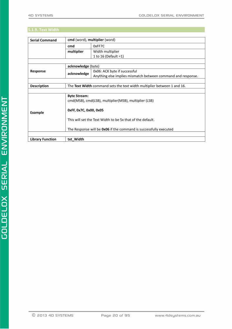
5.1.9. Text Width
Serial Command cmd (word), multiplier (word)
cmd 0xFF7C
multiplier Width multiplier 1 to 16 (Default =1)
Response
acknowledge (byte)
acknowledge 0x06: ACK byte if successful Anything else implies mismatch between command and response.
Description The Text Width command sets the text width multiplier between 1 and 16.
Example
Byte Stream: cmd(MSB), cmd(LSB), multiplier(MSB), multiplier (LSB) 0xFF, 0x7C, 0x00, 0x05 This will set the Text Width to be 5x that of the default. The Response will be 0x06 if the command is successfully executed
Library Function txt_Width
4D SYSTEMS GOLDELOX SERIAL ENVIRONMENT
© 2013 4D SYSTEMS Page 21 of 95 www.4dsystems.com.au
GOLD
ELO
X
SERIA
L E
NVIR
ONM
ENT
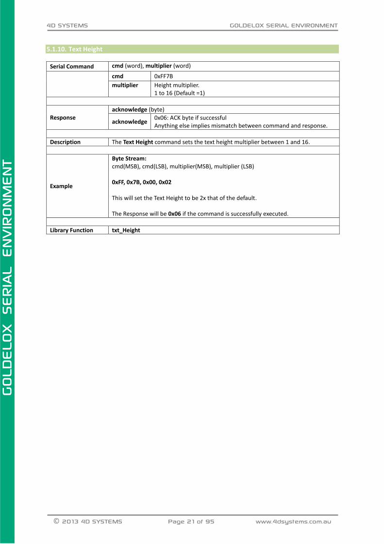
5.1.10. Text Height
Serial Command cmd (word), multiplier (word)
cmd 0xFF7B
multiplier Height multiplier. 1 to 16 (Default =1)
Response
acknowledge (byte)
acknowledge 0x06: ACK byte if successful Anything else implies mismatch between command and response.
Description The Text Height command sets the text height multiplier between 1 and 16.
Example
Byte Stream: cmd(MSB), cmd(LSB), multiplier(MSB), multiplier (LSB) 0xFF, 0x7B, 0x00, 0x02 This will set the Text Height to be 2x that of the default. The Response will be 0x06 if the command is successfully executed.
Library Function txt_Height

4D SYSTEMS GOLDELOX SERIAL ENVIRONMENT
© 2013 4D SYSTEMS Page 22 of 95 www.4dsystems.com.au
GOLD
ELO
X
SERIA
L E
NVIR
ONM
ENT
5.1.11. Text X-gap
Serial Command cmd (word), pixelcount (word)
cmd 0xFF7A
pixelcount 0 to 32(Default =0)
Response
acknowledge (byte)
acknowledge 0x06: ACK byte if successful Anything else implies mismatch between command and response.
Description The Text X-gap command sets the pixel gap between characters (x-axis), where the gap is in pixel units.
Example
Byte Stream: cmd(MSB), cmd(LSB), pixelcount(MSB), pixelcount(LSB) 0xFF, 0x7A, 0x00, 0x02 This will set the text X-Gap to be 2 pixels, where 2 pixels is 0x00, 0x02 The Response will be 0x06 if the command is successfully executed.
Library Function txt_Xgap

4D SYSTEMS GOLDELOX SERIAL ENVIRONMENT
© 2013 4D SYSTEMS Page 23 of 95 www.4dsystems.com.au
GOLD
ELO
X
SERIA
L E
NVIR
ONM
ENT
5.1.12. Text Y-gap
Serial Command cmd (word), pixelcount (word)
cmd 0xFF79
pixelcount 0 to 32(Default =0)
Response
acknowledge (byte)
acknowledge 0x06: ACK byte if successful Anything else implies mismatch between command and response.
Description The Text Y-gap command sets the pixel gap between characters (y-axis), where the gap is in pixel units.
Example
Byte Stream: cmd(MSB), cmd(LSB), pixelcount(MSB), pixelcount(LSB) 0xFF, 0x79, 0x00, 0x05 This will set the text Y-Gap to be 5 pixels, where 5 pixels is 0x00, 0x05 The Response will be 0x06 if the command is successfully executed.
Library Function txt_Ygap

4D SYSTEMS GOLDELOX SERIAL ENVIRONMENT
© 2013 4D SYSTEMS Page 24 of 95 www.4dsystems.com.au
GOLD
ELO
X
SERIA
L E
NVIR
ONM
ENT
5.1.13. Text Bold
Serial Command cmd (word), mode(word)
cmd 0xFF76
mode 1 for ON. 0 for OFF.
Response
acknowledge (byte)
acknowledge 0x06: ACK byte if successful Anything else implies mismatch between command and response.
Description
The Text Bold command sets the Bold attribute for the text. The ‘Text Bold’ attribute is cleared internally once the text (character or string) is displayed.
Example
Byte Stream: cmd(MSB), cmd(LSB), mode(MSB), mode(LSB) 0xFF, 0x76, 0x00, 0x01 This will set the text to be bold, Bold = ON The Response will be 0x06 if the command is successfully executed.
Library Function txt_Bold

4D SYSTEMS GOLDELOX SERIAL ENVIRONMENT
© 2013 4D SYSTEMS Page 25 of 95 www.4dsystems.com.au
GOLD
ELO
X
SERIA
L E
NVIR
ONM
ENT
5.1.14. Text Inverse
Serial Command cmd (word), mode (word)
cmd 0xFF74
mode 1 for ON. 0 for OFF.
Response
acknowledge (byte)
acknowledge 0x06: ACK byte if successful Anything else implies mismatch between command and response.
Description
The Text Inverse command inverts the text Foreground and Background colour. The ‘Text Inverse’ attribute is cleared internally once the text (character or string) is displayed.
Example
Byte Stream: cmd(MSB), cmd(LSB), mode(MSB), mode(LSB) 0xFF, 0x74, 0x00, 0x01 This will set the text Background and foreground colour to be inverse, where inverse = ON = 0x00, 0x01 The Response will be 0x06 if the command is successfully executed.
Library Function txt_Inverse
4D SYSTEMS GOLDELOX SERIAL ENVIRONMENT
© 2013 4D SYSTEMS Page 26 of 95 www.4dsystems.com.au
GOLD
ELO
X
SERIA
L E
NVIR
ONM
ENT
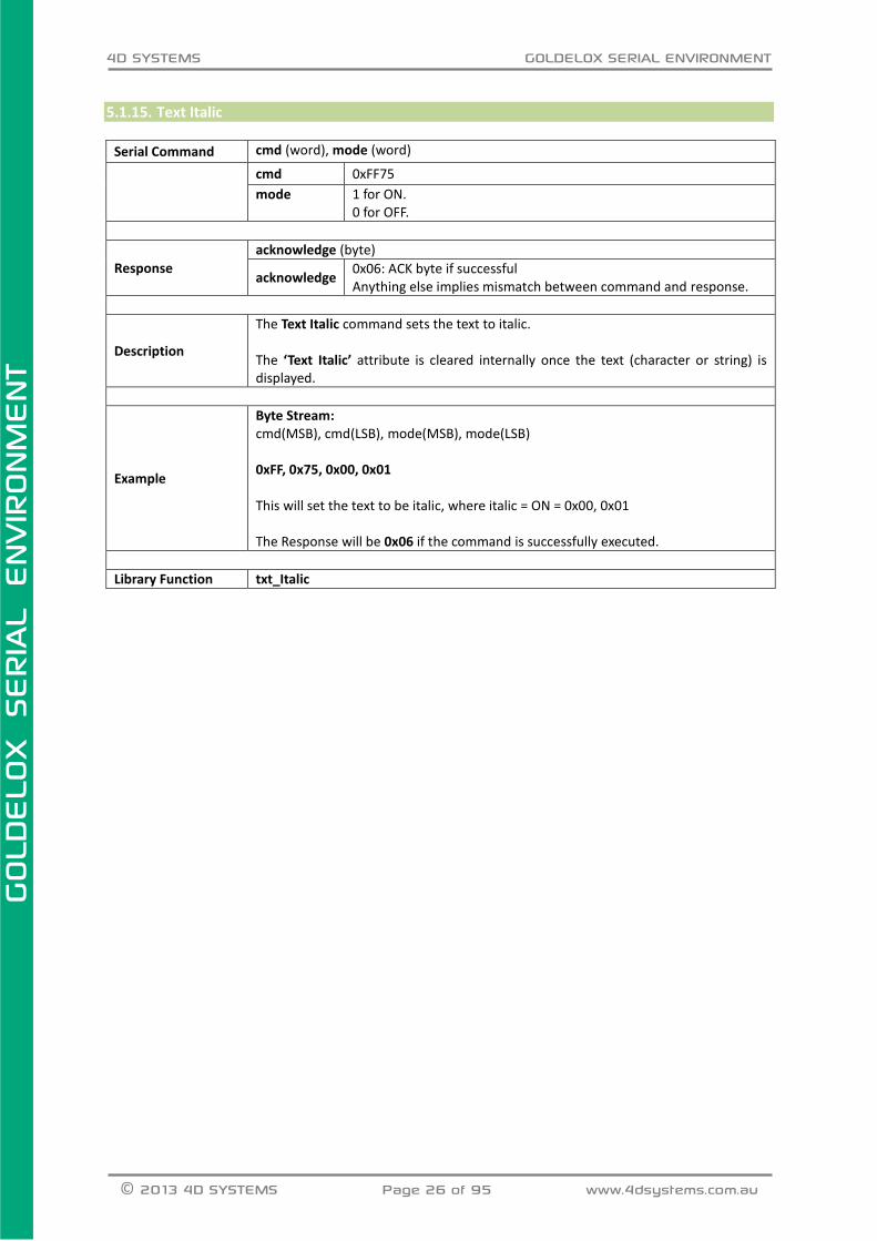
5.1.15. Text Italic
Serial Command cmd (word), mode (word)
cmd 0xFF75
mode 1 for ON. 0 for OFF.
Response
acknowledge (byte)
acknowledge 0x06: ACK byte if successful Anything else implies mismatch between command and response.
Description
The Text Italic command sets the text to italic. The ‘Text Italic’ attribute is cleared internally once the text (character or string) is displayed.
Example
Byte Stream: cmd(MSB), cmd(LSB), mode(MSB), mode(LSB) 0xFF, 0x75, 0x00, 0x01 This will set the text to be italic, where italic = ON = 0x00, 0x01 The Response will be 0x06 if the command is successfully executed.
Library Function txt_Italic
4D SYSTEMS GOLDELOX SERIAL ENVIRONMENT
© 2013 4D SYSTEMS Page 27 of 95 www.4dsystems.com.au
GOLD
ELO
X
SERIA
L E
NVIR
ONM
ENT
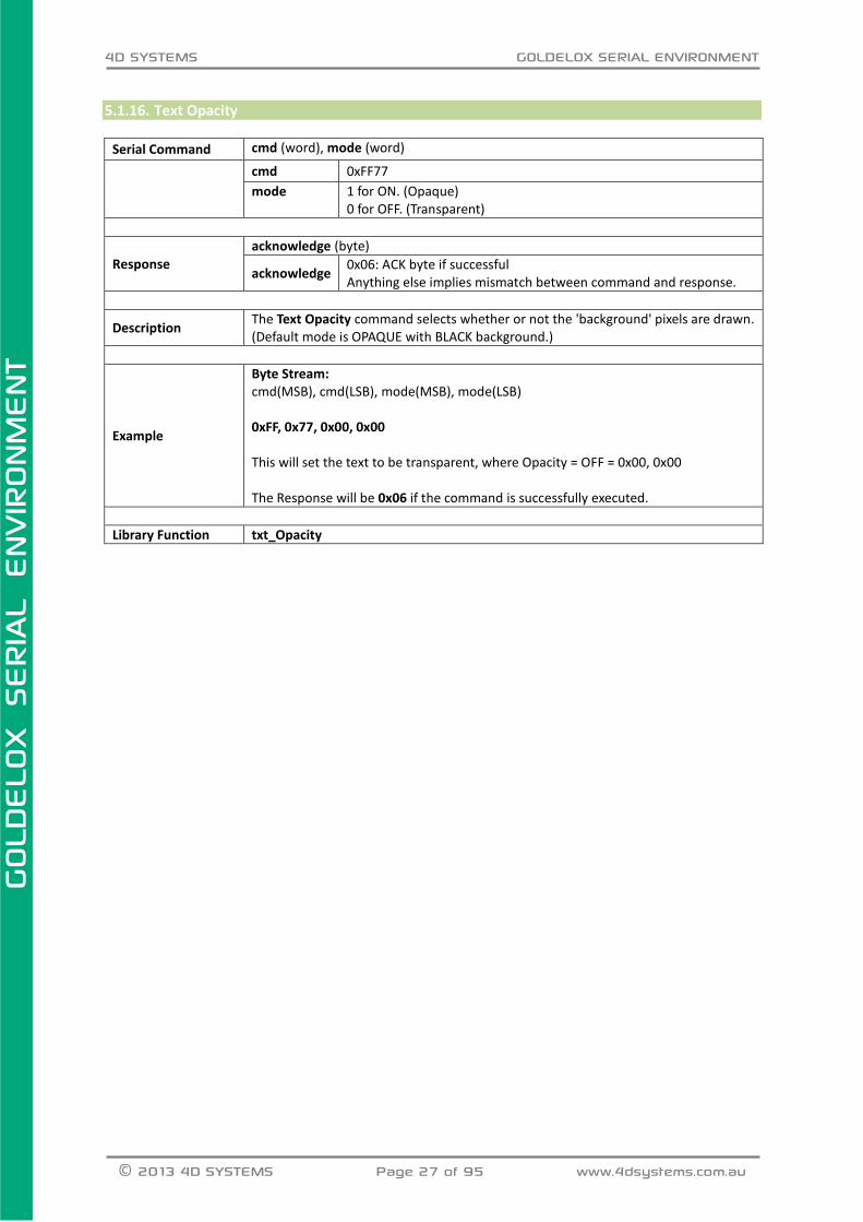
5.1.16. Text Opacity
Serial Command cmd (word), mode (word)
cmd 0xFF77
mode 1 for ON. (Opaque) 0 for OFF. (Transparent)
Response
acknowledge (byte)
acknowledge 0x06: ACK byte if successful Anything else implies mismatch between command and response.
Description The Text Opacity command selects whether or not the 'background' pixels are drawn. (Default mode is OPAQUE with BLACK background.)
Example
Byte Stream: cmd(MSB), cmd(LSB), mode(MSB), mode(LSB) 0xFF, 0x77, 0x00, 0x00 This will set the text to be transparent, where Opacity = OFF = 0x00, 0x00 The Response will be 0x06 if the command is successfully executed.
Library Function txt_Opacity

4D SYSTEMS GOLDELOX SERIAL ENVIRONMENT
© 2013 4D SYSTEMS Page 28 of 95 www.4dsystems.com.au
GOLD
ELO
X
SERIA
L E
NVIR
ONM
ENT
5.1.17. Text Underline
Serial Command cmd (word), mode (word)
cmd 0xFF73
mode 1 for ON. 0 for OFF.
Response
acknowledge (byte), value (word)
acknowledge 0x06: ACK byte if successful Anything else implies mismatch between command and response.
value Previous Text Underline status.
Description
The Text Underline command sets the text to underlined. The ‘Text Underline’ attribute is cleared internally once the text (character or string) is displayed.
Example
Byte Stream: cmd(MSB), cmd(LSB), mode(MSB), mode(LSB) 0xFF, 0x73, 0x00, 0x01 This will set the text to be underlined, where Underline = ON = 0x00, 0x01 The Response will be 0x06 if the command is successfully executed.
Library Function txt_Underline

4D SYSTEMS GOLDELOX SERIAL ENVIRONMENT
© 2013 4D SYSTEMS Page 29 of 95 www.4dsystems.com.au
GOLD
ELO
X
SERIA
L E
NVIR
ONM
ENT
5.1.18. Text Attributes
Serial Command cmd (word), value (word)
cmd 0xFF72
value (bit 5 or) DEC 16 for BOLD (bit 6 or) DEC 32 for ITALIC (bit 7 or) DEC 64 for INVERSE (bit 8 or) DEC 128 for UNDERLINED Set or Clear the relevant bits to set the attributes for the text to be written. (bits can be combined by using logical 'OR' of bits) NOTE: bits 0-3 and 8-15 are reserved
Response
acknowledge (byte)
acknowledge 0x06: ACK byte if successful Anything else implies mismatch between command and response.
Description
The Text Attributes command controls the following functions grouped, Text Bold Text Italic Text Inverse Text Underlined The Attributes are set to normal internally once the text (character or string) is displayed.
Example
Byte Stream: cmd(MSB), cmd(LSB), value(MSB), value(LSB) 0xFF, 0x72, 0x00, 0x90 This will set the Text Attributes to be Bold and Underlined. Where Bold has the value 16 and Underlined has the value 128, so 16+128=144 which is 0x90 in Hex. The Response will be 0x06 if the command is successfully executed.
Library Function txt_Attributes

4D SYSTEMS GOLDELOX SERIAL ENVIRONMENT
© 2013 4D SYSTEMS Page 30 of 95 www.4dsystems.com.au
GOLD
ELO
X
SERIA
L E
NVIR
ONM
ENT
5.1.19. Set Text Parameters
Serial Command cmd (word), function (word), value (word)
cmd 0xFFE3
function See the list below
value See the list below
function value
Function = 7 Text Print Delay Sets the Delay between the characters being printed through Put Character or Put String functions.
0 or 255 msec Default is 0 msec
Response
acknowledge (byte)
acknowledge 0x06: ACK byte if successful Anything else implies mismatch between command and response.
Description Sets various parameters for the Text commands.
Example
Byte Stream: cmd(MSB), cmd(LSB), function(MSB), function(LSB), value(MSB), value(LSB) 0xFF, 0xE3, 0x00, 0x07, 0x00, 0x96 This will set the Text Print Delay to be 150 (0x00, 0x96) The response will be 0x06 if successful
Library Function gfx_Set

4D SYSTEMS GOLDELOX SERIAL ENVIRONMENT
© 2013 4D SYSTEMS Page 31 of 95 www.4dsystems.com.au
GOLD
ELO
X
SERIA
L E
NVIR
ONM
ENT
5.2. Graphics Commands The following is a summary of the commands available to be used for Graphics:
Clear Screen
Change Colour
Draw Circle
Draw Filled Circle
Draw Line
Draw Rectangle
Draw Filled Rectangle
Draw Polyline
Draw Polygon
Draw Triangle
Calculate Orbit
Put Pixel
Read Pixel
Move Origin
Draw Line and Move Origin
Clipping
Set Clip Window
Extend Clip Region
Background Colour
Outline Colour
Contrast
Frame Delay
Line Pattern
Screen Mode
Transparency
Transparent Colour
Set Graphics Parameters

4D SYSTEMS GOLDELOX SERIAL ENVIRONMENT
© 2013 4D SYSTEMS Page 32 of 95 www.4dsystems.com.au
GOLD
ELO
X
SERIA
L E
NVIR
ONM
ENT
5.2.1. Clear Screen
Serial Command cmd (word)
cmd 0xFFD7
Response
acknowledge (byte)
acknowledge 0x06: ACK byte if successful Anything else implies mismatch between command and response.
Description
The Clear Screen command clears the screen using the current background colour. This command brings some of the settings back to default; such as,
Outline colour set to BLACK
Pen set to OUTLINE
Text magnifications set to 1
All origins set to 0:0 The alternative to maintain settings and clear screen is to draw a filled rectangle with the required background colour.
Example
Byte Stream: cmd(MSB), cmd(LSB) 0xFF, 0xD7 The following will clear the display and restore the settings back to their defaults. The response will be 0x06 if the command is successful
Library Function gfx_Cls

4D SYSTEMS GOLDELOX SERIAL ENVIRONMENT
© 2013 4D SYSTEMS Page 33 of 95 www.4dsystems.com.au
GOLD
ELO
X
SERIA
L E
NVIR
ONM
ENT
5.2.2. Change Colour
Serial Command cmd (word), oldColour (word), newColour (word)
cmd 0xFFBE
oldColour Specifies the sample colour to be changed within the clipping window.
newColour Specifies the new colour to change all occurrences of old colour within the clipping window.
Response acknowledge (byte)
acknowledge 0x06: ACK byte if successful Anything else implies mismatch between command and response.
Description The Change Colour command changes all oldColour pixels to newColour within the
clipping window area.
Example
Byte Stream: cmd(MSB), cmd(LSB), oldColour(MSB), oldColour (LSB), newColour(MSB), newColour (LSB) 0xFF, 0xBE, 0x00, 0x00, 0x00, 0x1F This will change all pixels coloured Black (0x00, 0x00) to be coloured Blue (0x00, 0x1F) within the clipping area. (Refer to the Clip Window command for more information on this.) The Response will be 0x06 if the command is successful
Library Function gfx_ChangeColour
4D SYSTEMS GOLDELOX SERIAL ENVIRONMENT
© 2013 4D SYSTEMS Page 34 of 95 www.4dsystems.com.au
GOLD
ELO
X
SERIA
L E
NVIR
ONM
ENT
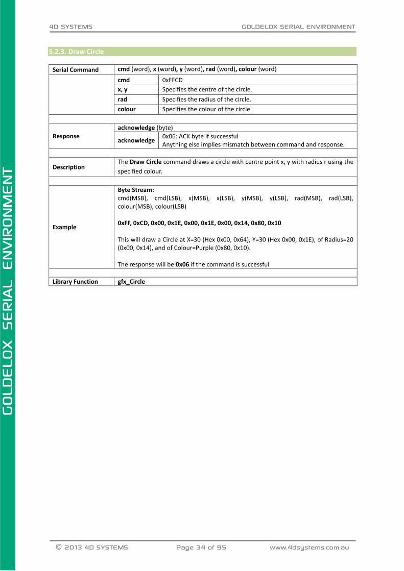
5.2.3. Draw Circle
Serial Command cmd (word), x (word), y (word), rad (word), colour (word)
cmd 0xFFCD
x, y Specifies the centre of the circle.
rad Specifies the radius of the circle.
colour Specifies the colour of the circle.
Response
acknowledge (byte)
acknowledge 0x06: ACK byte if successful Anything else implies mismatch between command and response.
Description The Draw Circle command draws a circle with centre point x, y with radius r using the
specified colour.
Example
Byte Stream: cmd(MSB), cmd(LSB), x(MSB), x(LSB), y(MSB), y(LSB), rad(MSB), rad(LSB), colour(MSB), colour(LSB) 0xFF, 0xCD, 0x00, 0x1E, 0x00, 0x1E, 0x00, 0x14, 0x80, 0x10 This will draw a Circle at X=30 (Hex 0x00, 0x64), Y=30 (Hex 0x00, 0x1E), of Radius=20 (0x00, 0x14), and of Colour=Purple (0x80, 0x10). The response will be 0x06 if the command is successful
Library Function gfx_Circle

4D SYSTEMS GOLDELOX SERIAL ENVIRONMENT
© 2013 4D SYSTEMS Page 35 of 95 www.4dsystems.com.au
GOLD
ELO
X
SERIA
L E
NVIR
ONM
ENT
5.2.4. Draw Filled Circle
Serial Command cmd (word), x (word), y (word), rad (word), colour (word)
cmd 0xFFCC
x, y Specifies the centre of the circle.
rad Specifies the radius of the circle.
colour Specifies the colour of the circle.
Response
acknowledge (byte)
acknowledge 0x06: ACK byte if successful Anything else implies mismatch between command and response.
Description
The Draw Circle command draws a solid circle with centre point x1, y1 with radius
using the specified colour.
The outline colour can be specified with the “Outline Colour” command.
If “Outline Colour” is set to 0, no outline is drawn.
Example
Byte Stream: cmd(MSB), cmd(LSB), x(MSB), x(LSB), y(MSB), y(LSB), rad(MSB), rad(LSB), colour(MSB), colour(LSB) 0xFF, 0xCC, 0x00, 0x2D, 0x00, 0x28, 0x00, 0x23, 0x84, 0x10 This will draw a Solid Filled Circle at X=45 (Hex 0x00, 0x2D), Y=40 (Hex 0x00, 0x28), of Radius=35 (0x00, 0x23), and of Colour=Grey (0x84, 0x10). The response will be 0x06 if the command is successful
Library Function gfx_CircleFilled
4D SYSTEMS GOLDELOX SERIAL ENVIRONMENT
© 2013 4D SYSTEMS Page 36 of 95 www.4dsystems.com.au
GOLD
ELO
X
SERIA
L E
NVIR
ONM
ENT
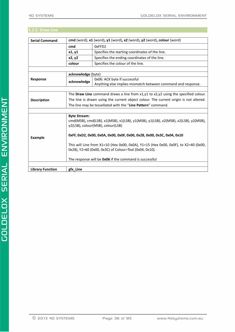
5.2.5. Draw Line
Serial Command cmd (word), x1 (word), y1 (word), x2 (word), y2 (word), colour (word)
cmd 0xFFD2
x1, y1 Specifies the starting coordinates of the line.
x2, y2 Specifies the ending coordinates of the line.
colour Specifies the colour of the line.
Response
acknowledge (byte)
acknowledge 0x06: ACK byte if successful Anything else implies mismatch between command and response.
Description
The Draw Line command draws a line from x1,y1 to x2,y2 using the specified colour.
The line is drawn using the current object colour. The current origin is not altered.
The line may be tessellated with the “Line Pattern” command.
Example
Byte Stream: cmd(MSB), cmd(LSB), x1(MSB), x1(LSB), y1(MSB), y1(LSB), x2(MSB), x2(LSB), y2(MSB), y2(LSB), colour(MSB), colour(LSB) 0xFF, 0xD2, 0x00, 0x0A, 0x00, 0x0F, 0x00, 0x28, 0x00, 0x3C, 0x04, 0x10 This will Line from X1=10 (Hex 0x00, 0x0A), Y1=15 (Hex 0x00, 0x0F), to X2=40 (0x00, 0x28), Y2=60 (0x00, 0x3C) of Colour=Teal (0x04, 0x10). The response will be 0x06 if the command is successful
Library Function gfx_Line

4D SYSTEMS GOLDELOX SERIAL ENVIRONMENT
© 2013 4D SYSTEMS Page 37 of 95 www.4dsystems.com.au
GOLD
ELO
X
SERIA
L E
NVIR
ONM
ENT
5.2.6. Draw Rectangle
Serial Command cmd (word), x1 (word), y1 (word), x2 (word), y2 (word), colour (word)
cmd 0xFFCF
x1, y1 Specifies the top left corner of the rectangle.
x2, y2 Specifies the bottom right corner of the rectangle.
colour Specifies the colour of the rectangle.
Response
acknowledge (byte)
acknowledge 0x06: ACK byte if successful Anything else implies mismatch between command and response.
Description The Draw Rectangle command draws a rectangle from x1, y1 to x2, y2 using the specified colour. The line may be tessellated with the “Line Pattern” command.
Example
Byte Stream: cmd(MSB), cmd(LSB), x1(MSB), x1(LSB), y1(MSB), y1(LSB), x2(MSB), x2(LSB), y2(MSB), y2(LSB), colour(MSB), colour(LSB) 0xFF, 0xCF, 0x00, 0x0A, 0x00, 0x14, 0x00, 0x5A, 0x00, 0x3C, 0xF8, 0x00 The will draw a Rectangle from X1=10 (0x00, 0x0A), Y1=20 (0x00, 0x14), to X2=90 (0x00, 0x5A), Y2=60 (0x00, 0x3C), of colour=Red (0xF8, 0x00). The response will be 0x06 if the command is successful
Library Function gfx_Rectangle

4D SYSTEMS GOLDELOX SERIAL ENVIRONMENT
© 2013 4D SYSTEMS Page 38 of 95 www.4dsystems.com.au
GOLD
ELO
X
SERIA
L E
NVIR
ONM
ENT
5.2.7. Draw Filled Rectangle
Serial Command cmd (word), x1 (word), y1 (word), x2 (word), y2 (word), colour (word)
cmd 0xFFCE
x1, y1 Specifies the top left corner of the rectangle.
x2, y2 Specifies the bottom right corner of the rectangle.
colour Specifies the colour of the rectangle.
Response
acknowledge (byte)
acknowledge 0x06: ACK byte if successful Anything else implies mismatch between command and response.
Description
The Draw Filled Rectangle command draws a solid rectangle from x1, y1 to x2, y2
using the specified colour. The line may be tessellated with the “Line Pattern”
command.
The outline colour can be specified with the “Outline Colour” command. If “Outline
Colour” is set to 0, no outline is drawn.
Example
Byte Stream: cmd(MSB), cmd(LSB), x1(MSB), x1(LSB), y1(MSB), y1(LSB), x2(MSB), x2(LSB), y2(MSB), y2(LSB), colour(MSB), colour(LSB) 0xFF, 0xCE, 0x00, 0x0A, 0x00, 0x14, 0x00, 0x5A, 0x00, 0x3C, 0x07, 0xE0 The will draw a Solid Filled Rectangle from X1=10 (0x00, 0x0A), Y1=20 (0x00, 0x14), to X2=90 (0x00, 0x5A), Y2=60 (0x00, 0x3C), of colour=Lime (0x07, 0xE0). The response will be 0x06 if the command is successful
Library Function gfx_RectangleFilled

4D SYSTEMS GOLDELOX SERIAL ENVIRONMENT
© 2013 4D SYSTEMS Page 39 of 95 www.4dsystems.com.au
GOLD
ELO
X
SERIA
L E
NVIR
ONM
ENT
5.2.8. Draw Polyline
Serial Command cmd (word), n (word), vx1 (word)…vxN (word), vy1 (word)…vyN (word), colour (word)
cmd 0x0005
n Specifies the number of elements in the x and y arrays specifying the
vertices for the polyline.
vx, vy
Specifies the array of elements for the x/y coordinates of the
vertices.
Vx1, vx2, …, vxN, vy1, vy2, …, vyN
colour Specifies the colour of the polyline.
Response
acknowledge (byte)
acknowledge 0x06: ACK byte if successful Anything else implies mismatch between command and response.
Description
The Draw Polyline command plots lines between points specified by a pair of arrays
using the specified colour. The lines may be tessellated with the “Line Pattern”
command. The “Draw Polyline” command can be used to create complex raster
graphics by loading the arrays from serial input or from MEDIA with very little code
requirement.
Example
Byte Stream: cmd(MSB), cmd(LSB), n(MSB), n(LSB), vx1(MSB), vx1(LSB), vx2(MSB), vx2(LSB), vx3(MSB), vx3(LSB), vy1(MSB), vy1(LSB), vy2(MSB), vy2(LSB), vy3(MSB), vy3(LSB), colour(MSB), colour(LSB) 0x00, 0x05, 0x00, 0x03, 0x00, 0x0A, 0x00, 0x3C, 0x00, 0x78, 0x00, 0x05, 0x00, 0x50, 0x00, 0x5A, 0x80, 0x00 The following will draw a 3 point Polyline from X1=10 (0x00, 0x0A), Y1=5 (0x00, 0x05), to X2=60 (0x00, 0x3C), Y2=80 (0x00, 0x50), and finally to X3=120 (0x00, 0x78), Y3=90 (0x00, 0x5A) of Colour=Maroon (0x80, 0x00) The response will be 0x06 if the command is successful
Library Function gfx_Polyline

4D SYSTEMS GOLDELOX SERIAL ENVIRONMENT
© 2013 4D SYSTEMS Page 40 of 95 www.4dsystems.com.au
GOLD
ELO
X
SERIA
L E
NVIR
ONM
ENT
5.2.9. Draw Polygon
Serial Command cmd (word), n (word), vx1 (word)…vxN (word), vy1 (word)…vyN (word), colour (word)
cmd 0x0004
n Specifies the number of elements in the x and y arrays specifying the
vertices for the polygon.
vx, vy
Specifies the array of elements for the x/y coordinates of the
vertices.
Vx1, vx2, …, vxN, vy1, vy2, …, vyN
colour Specifies the colour of the polygon.
Response
acknowledge (byte)
acknowledge 0x06: ACK byte if successful Anything else implies mismatch between command and response.
Description
The Draw Polygon command plots lines between points specified by a pair of arrays
using the specified colour. The last point is drawn back to the first point, completing
the polygon. The lines may be tessellated with “Line Pattern” command. The Draw
Polygon command can be used to create complex raster graphics by loading the
arrays from serial input or from MEDIA with very little code requirement.
Example
Byte Stream: cmd(MSB), cmd(LSB), n(MSB), n(LSB), vx1(MSB), vx1(LSB), vx2(MSB), vx2(LSB), vx3(MSB), vx3(LSB), vy1(MSB), vy1(LSB), vy2(MSB), vy2(LSB), vy3(MSB), vy3(LSB), vy4(MSB),colour(MSB), colour(LSB) 0x00, 0x04, 0x00, 0x03, 0x00, 0x0A, 0x00, 0x3C, 0x00, 0x78, 0x00, 0x05, 0x00, 0x50, 0x00, 0x5A, 0xFF, 0xE0 The following will draw a 3 point Polygon from X1=10 (0x00, 0x0A), Y1=5 (0x00, 0x05), to X2=60 (0x00, 0x3C), Y2=80 (0x00, 0x50), and finally to X3=120 (0x00, 0x78), Y3=90 (0x00, 0x5A) of Colour=Yellow (0xFF, 0xE0) The response will be 0x06 if the command is successful
Library Function gfx_Polygon

4D SYSTEMS GOLDELOX SERIAL ENVIRONMENT
© 2013 4D SYSTEMS Page 41 of 95 www.4dsystems.com.au
GOLD
ELO
X
SERIA
L E
NVIR
ONM
ENT
5.2.10. Draw Triangle
Serial Command cmd (word), x1 (word), y1 (word), x2 (word), y2 (word), x3 (word), y3 (word), colour (word)
cmd 0xFFC9
x1, y1 Specifies the first vertice of the triangle.
x2, y2 Specifies the second vertice of the triangle.
x3, y3 Specifies the third vertice of the triangle.
colour Specifies the colour of the triangle.
Response
acknowledge (byte)
acknowledge 0x06: ACK byte if successful Anything else implies mismatch between command and response.
Description
The Draw Triangle command draws a triangle outline between vertices x1,y1 , x2,y2
and x3,y3 using the specified colour. The line may be tessellated with the “Line
Pattern” command.
Example
Byte Stream: cmd(MSB), cmd(LSB), x1(MSB), x1(LSB), y1(MSB), y1(LSB), x2(MSB), x2(LSB), y2(MSB), y2(LSB), x3(MSB), x3(LSB), y3(MSB), y3(LSB), colour(MSB), colour(LSB) 0xFF, 0xC9, 0x00, 0x00, 0x00, 0x00, 0x00, 0x28, 0x00, 0x28, 0x00, 0x00, 0x00, 0x28, 0x07, 0xFF This will draw a Triangle from X1=00 (0x00, 0x00), Y1=00 (0x00, 0x00), to X2=40 (0x00, 0x28), Y2=40 (0x00, 0x28), to X3=00 (0x00, 0x00), Y3=40 (0x00, 0x28) of colour=Aqua (0x07, 0xFF) The response will be 0x06 if the command is successful
Library Function gfx_Triangle

4D SYSTEMS GOLDELOX SERIAL ENVIRONMENT
© 2013 4D SYSTEMS Page 42 of 95 www.4dsystems.com.au
GOLD
ELO
X
SERIA
L E
NVIR
ONM
ENT
5.2.11. Calculate Orbit
Serial Command cmd (word), angle (word), distance (word)
cmd 0x0003
angle Specifies the angle from the origin to the remote point. The angle is
specified in degrees.
distance Specifies the distance from the origin to the remote point in pixel
units.
Response
acknowledge (byte), Xdist (word), Ydist (word)
acknowledge 0x06: ACK byte if successful Anything else implies mismatch between command and response.
Xdist X coordinate from the current origin.
Ydist Y coordinate from the current origin.
Description
The Calculate Orbit command calculates the x, y coordinates of a distant point
relative to the current origin, where the only known parameters are the angle and
the distance from the current origin.
Example
Byte Stream: cmd(MSB), cmd(LSB), angle(MSB), angle(LSB), distance(MSB), distance(LSB) 0x00, 0x03, 0x00, 0x2D, 0x00, 0x3C This will calculate the x and y coordinates based on the Angle=45 degrees (0x00, 0x2D) and the Distance=60 pixels (0x00, 0x3C) from the current origin. The response will be 0x06, 0x00, 0x29, 0x00, 0x29 assuming the origin is at X=0, Y=0. The coordinates are X=41 (0x00, 0x29) and Y=41 (0x00, 0x29)
Library Function gfx_Orbit

4D SYSTEMS GOLDELOX SERIAL ENVIRONMENT
© 2013 4D SYSTEMS Page 43 of 95 www.4dsystems.com.au
GOLD
ELO
X
SERIA
L E
NVIR
ONM
ENT
5.2.12. Put pixel
Serial Command cmd (word), x (word), y (word), colour (word)
cmd 0xFFCB
x, y Specifies the pixel x, y coordinates.
colour Specifies the colour of the pixel.
Response acknowledge (byte)
acknowledge 0x06: ACK byte if successful Anything else implies mismatch between command and response.
Description The Put Pixel command draws a pixel at position x, y using the specified colour.
Example
Byte Stream: cmd(MSB), cmd(LSB), x(MSB), x(LSB), y(MSB), y(LSB), colour(MSB), colour(LSB) 0xFF, 0xCB, 0x00, 0x28, 0x00, 0x32, 0xFF, 0xE0 This will put a pixel at X=40 (0x00, 0x28), Y=50 (0x00, 0x32), and colour the pixel Yellow (0xFF, 0xE0). The response will be 0x06 if the command is successful
Library Function gfx_PutPixel

4D SYSTEMS GOLDELOX SERIAL ENVIRONMENT
© 2013 4D SYSTEMS Page 44 of 95 www.4dsystems.com.au
GOLD
ELO
X
SERIA
L E
NVIR
ONM
ENT
5.2.13. Read Pixel
Serial Command cmd (word), x (word), y (word)
cmd 0xFFCA
x, y Specifies the pixel x, y coordinates.
Response
acknowledge (byte), colour (word)
acknowledge 0x06: ACK byte if successful Anything else implies mismatch between command and response.
colour 16bit colour of the pixel
Description The Read Pixel command reads the colour value of the pixel at position x,y.
Example
Byte Stream: cmd(MSB), cmd(LSB), x(MSB), x(LSB), y(MSB), y(LSB) 0xFF, 0xCA, 0x00, 0x28, 0x00, 0x32 This will read the colour of a pixel at X=40 (0x00, 0x28), Y=50 (0x00, 0x32) The response will be 0x06, 0xFF, 0xE0 if the command is successful, assuming the pixel being read is coloured Yellow (0xFF, 0xE0)
Library Function gfx_GetPixel

4D SYSTEMS GOLDELOX SERIAL ENVIRONMENT
© 2013 4D SYSTEMS Page 45 of 95 www.4dsystems.com.au
GOLD
ELO
X
SERIA
L E
NVIR
ONM
ENT
5.2.14. Move Origin
Serial Command cmd (word), xpos (word), ypos (word)
cmd 0xFFD6
xpos, ypos Specifies the horizontal and vertical position of the new origin.
Response
acknowledge (byte)
acknowledge 0x06: ACK byte if successful Anything else implies mismatch between command and response.
Description The Move Origin command moves the origin to a new position.
Example
Byte Stream: cmd(MSB), cmd(LSB), xpos(MSB), xpos(LSB), ypos(MSB), ypos(LSB) 0xFF, 0xD6, 0x00, 0x32, 0x00, 0x5A This will move the Origin to be X=50 (0x00, 0x32), Y=90 (0x00, 0x5A) The response will be 0x06 if the command is successful
Library Function gfx_MoveTo

4D SYSTEMS GOLDELOX SERIAL ENVIRONMENT
© 2013 4D SYSTEMS Page 46 of 95 www.4dsystems.com.au
GOLD
ELO
X
SERIA
L E
NVIR
ONM
ENT
5.2.15. Draw Line & Move Origin
Serial Command cmd (word), xpos (word), ypos (word)
cmd 0xFFD4
xpos, ypos Specifies the horizontal and vertical position of the line end as well as
the new origin.
Response
acknowledge (byte)
acknowledge 0x06: ACK byte if successful Anything else implies mismatch between command and response.
Description
The Draw Line & Move Origin command draws a line from the current origin to a
new position. The Origin is then set to the new position. The line is drawn using the
current object colour, using the “Set Graphics Parameters” – “Object Colour”
command. The line may be tessellated with the “Line Pattern” command.
Note: this command is mostly useful with the “Calculate Orbit” command, and
usually the “Draw Line” command would be used
Example
Byte Stream: cmd(MSB), cmd(LSB), xpos(MSB), xpos(LSB), ypos(MSB), ypos(LSB) 0xFF, 0xD4, 0x00, 0x32, 0x00, 0x46 This will draw a line from the current origin (assuming this is X=0, Y=0 for this example) to X=50 (0x00, 0x32), Y=70 (0x00, 0x46) and set the origin to be this point (X=50, Y=70). The response will be 0x06 if the command is successful
Library Function gfx_LineTo
4D SYSTEMS GOLDELOX SERIAL ENVIRONMENT
© 2013 4D SYSTEMS Page 47 of 95 www.4dsystems.com.au
GOLD
ELO
X
SERIA
L E
NVIR
ONM
ENT
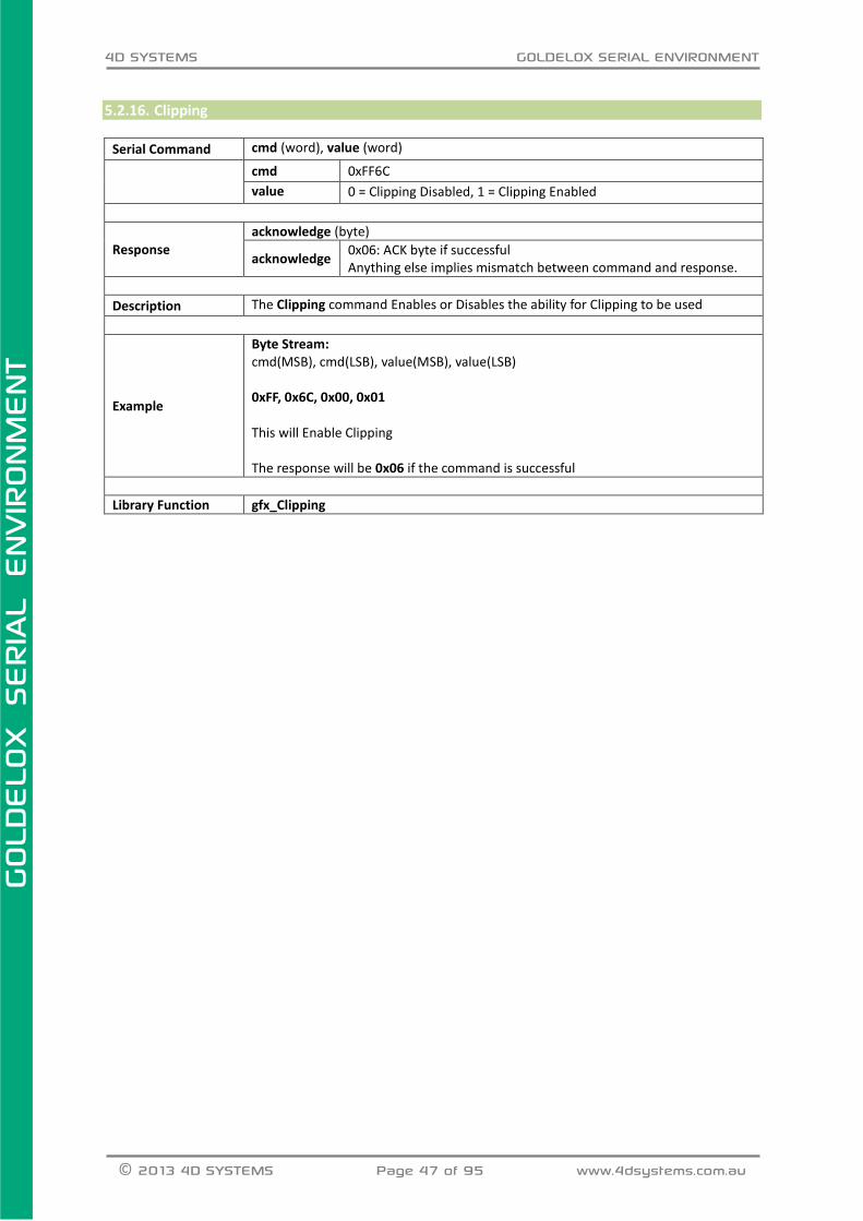
5.2.16. Clipping
Serial Command cmd (word), value (word)
cmd 0xFF6C
value 0 = Clipping Disabled, 1 = Clipping Enabled
Response
acknowledge (byte)
acknowledge 0x06: ACK byte if successful Anything else implies mismatch between command and response.
Description The Clipping command Enables or Disables the ability for Clipping to be used
Example
Byte Stream: cmd(MSB), cmd(LSB), value(MSB), value(LSB) 0xFF, 0x6C, 0x00, 0x01 This will Enable Clipping The response will be 0x06 if the command is successful
Library Function gfx_Clipping

4D SYSTEMS GOLDELOX SERIAL ENVIRONMENT
© 2013 4D SYSTEMS Page 48 of 95 www.4dsystems.com.au
GOLD
ELO
X
SERIA
L E
NVIR
ONM
ENT
5.2.17. Set Clip Window
Serial Command cmd (word), x1 (word), y1 (word), x2 (word), y2 (word)
cmd 0xFFBF
x1, y1 Specifies the horizontal and vertical position of the top left corner of
the clipping window.
x2, y2 Specifies the horizontal and vertical position of the bottom right
corner of the clipping window.
Response acknowledge (byte)
acknowledge 0x06: ACK byte if successful Anything else implies mismatch between command and response.
Description
The Set Clip Window command specifies a clipping window region on the screen
such that any objects and text placed onto the screen will be clipped and displayed
only within that region. For the clipping window to take effect, the clipping setting
must be enabled separately using the “Clipping” command
Example
Byte Stream: cmd(MSB), cmd(LSB), x1(MSB), x1(LSB), y1(MSB), y1(LSB), x2(MSB), x2(LSB), y2(MSB), y2(LSB) 0xFF, 0xBF, 0x00, 0x00, 0x00, 0x00, 0x00, 0x28, 0x00, 0x28 This will set the top left of the Clipping Window Region to be X1=0 (0x00, 0x00), Y1=0 (0x00, 0x00), and bottom right to be X2=40 (0x00, 0x28), Y2=40 (0x00, 0x28) The response will be 0x06 if the command is successful
Library Function gfx_ClipWindow

4D SYSTEMS GOLDELOX SERIAL ENVIRONMENT
© 2013 4D SYSTEMS Page 49 of 95 www.4dsystems.com.au
GOLD
ELO
X
SERIA
L E
NVIR
ONM
ENT
5.2.18. Extend Clip Region
Serial Command cmd (word)
cmd 0xFFBC
Response
acknowledge (byte)
acknowledge 0x06: ACK byte if successful Anything else implies mismatch between command and response.
Description The Extend Clip Region command forces the clip region to the extent of the last text
that was printed, or the last image that was shown.
Example
Byte Stream: cmd(MSB), cmd(LSB) 0xFF, 0xBC This will extend the clip region to the extent of the last text or image that was shown. The response will be 0x06 if the command is successful.
Library Function gfx_SetClipRegion

4D SYSTEMS GOLDELOX SERIAL ENVIRONMENT
© 2013 4D SYSTEMS Page 50 of 95 www.4dsystems.com.au
GOLD
ELO
X
SERIA
L E
NVIR
ONM
ENT
5.2.19. Background Colour
Serial Command cmd (word), colour (word)
cmd 0xFF6E
colour Specifies the colour to be set (0-65535 or HEX 0x0000-0xFFFF)
Response
acknowledge (byte)
acknowledge 0x06: ACK byte if successful Anything else implies mismatch between command and response.
Description The Background Colour command sets the screen background colour
Example
Byte Stream: cmd(MSB), cmd(LSB), colour(MSB), colour(LSB) 0xFF, 0x6E, 0x00, 0x10 This will set the Background Colour to be Navy (0x00, 0x10) The response will be 0x06 if the command is successful.
Library Function gfx_BGcolour
4D SYSTEMS GOLDELOX SERIAL ENVIRONMENT
© 2013 4D SYSTEMS Page 51 of 95 www.4dsystems.com.au
GOLD
ELO
X
SERIA
L E
NVIR
ONM
ENT
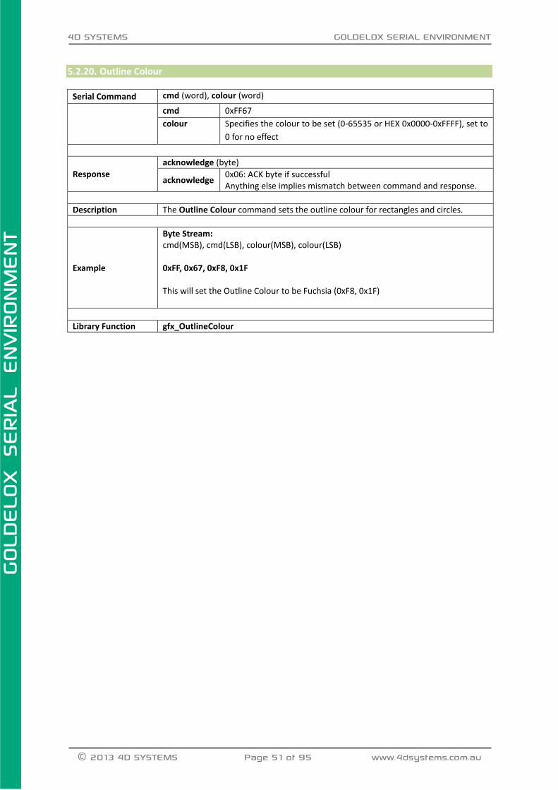
5.2.20. Outline Colour
Serial Command cmd (word), colour (word)
cmd 0xFF67
colour Specifies the colour to be set (0-65535 or HEX 0x0000-0xFFFF), set to
0 for no effect
Response
acknowledge (byte)
acknowledge 0x06: ACK byte if successful Anything else implies mismatch between command and response.
Description The Outline Colour command sets the outline colour for rectangles and circles.
Example
Byte Stream: cmd(MSB), cmd(LSB), colour(MSB), colour(LSB) 0xFF, 0x67, 0xF8, 0x1F This will set the Outline Colour to be Fuchsia (0xF8, 0x1F)
Library Function gfx_OutlineColour

4D SYSTEMS GOLDELOX SERIAL ENVIRONMENT
© 2013 4D SYSTEMS Page 52 of 95 www.4dsystems.com.au
GOLD
ELO
X
SERIA
L E
NVIR
ONM
ENT
5.2.21. Contrast
Serial Command cmd (word), contrast (word)
cmd 0xFF66
contrast Contrast 0 = Display OFF Contrast 1 - 15 = Contrast Level EXCEPTION: uLCD-144-G2 does not support Contrast ‘levels’, values from 1-15 could be set to turn the display ‘On’ and 0 to turn the Display ‘Off’.
Response
acknowledge (byte)
acknowledge 0x06: ACK byte if successful Anything else implies mismatch between command and response.
Description The Contrast Command sets the contrast of the display, or turns it On/Off depending
on display model
Example
Byte Stream: cmd(MSB), cmd(LSB), contrast(MSB), contrast(LSB) 0xFF, 0x66, 0x00, 0x09 This will set the Contrast of the display (example is a uOLED-128-G2) to be 9.
Library Function gfx_Contrast

4D SYSTEMS GOLDELOX SERIAL ENVIRONMENT
© 2013 4D SYSTEMS Page 53 of 95 www.4dsystems.com.au
GOLD
ELO
X
SERIA
L E
NVIR
ONM
ENT
5.2.22. Frame Delay
Serial Command cmd (word), Msec (word)
cmd 0xFF69
Msec 0-255 milliseconds
Response
acknowledge (byte), value (word)
acknowledge 0x06: ACK byte if successful Anything else implies mismatch between command and response.
value Previous Frame Delay value.
Description The Frame Delay command sets the inter frame delay for the “Media Video” command
Example
Byte Stream: cmd(MSB), cmd(LSB), Msec(MSB), Msec(LSB) 0xFF, 0x69, 0x00, 0x05 This will set the frame delay to 5 milliseconds The response will be 0x06 if the command is successful.
Library Function gfx_FrameDelay
4D SYSTEMS GOLDELOX SERIAL ENVIRONMENT
© 2013 4D SYSTEMS Page 54 of 95 www.4dsystems.com.au
GOLD
ELO
X
SERIA
L E
NVIR
ONM
ENT
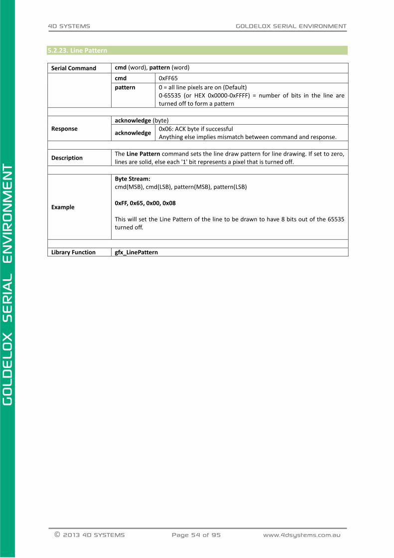
5.2.23. Line Pattern
Serial Command cmd (word), pattern (word)
cmd 0xFF65
pattern 0 = all line pixels are on (Default) 0-65535 (or HEX 0x0000-0xFFFF) = number of bits in the line are turned off to form a pattern
Response acknowledge (byte)
acknowledge 0x06: ACK byte if successful Anything else implies mismatch between command and response.
Description The Line Pattern command sets the line draw pattern for line drawing. If set to zero, lines are solid, else each '1' bit represents a pixel that is turned off.
Example
Byte Stream: cmd(MSB), cmd(LSB), pattern(MSB), pattern(LSB) 0xFF, 0x65, 0x00, 0x08 This will set the Line Pattern of the line to be drawn to have 8 bits out of the 65535 turned off.
Library Function gfx_LinePattern
4D SYSTEMS GOLDELOX SERIAL ENVIRONMENT
© 2013 4D SYSTEMS Page 55 of 95 www.4dsystems.com.au
GOLD
ELO
X
SERIA
L E
NVIR
ONM
ENT
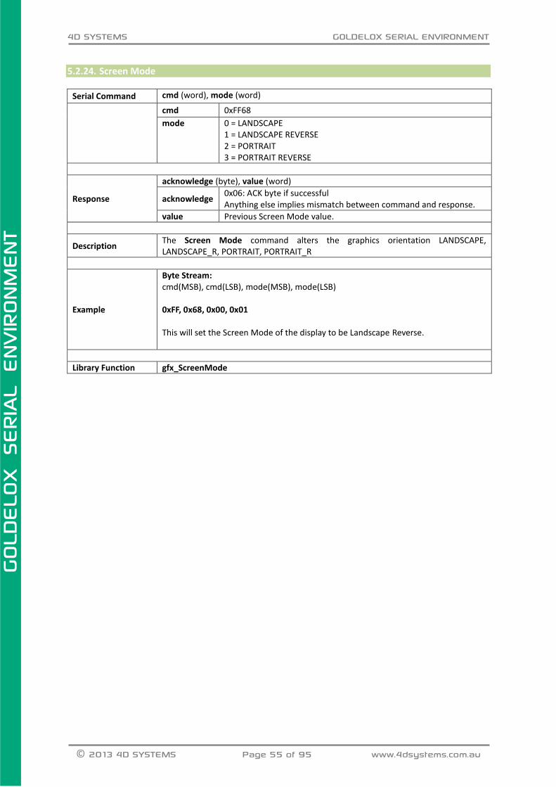
5.2.24. Screen Mode
Serial Command cmd (word), mode (word)
cmd 0xFF68
mode 0 = LANDSCAPE 1 = LANDSCAPE REVERSE 2 = PORTRAIT 3 = PORTRAIT REVERSE
Response
acknowledge (byte), value (word)
acknowledge 0x06: ACK byte if successful Anything else implies mismatch between command and response.
value Previous Screen Mode value.
Description The Screen Mode command alters the graphics orientation LANDSCAPE, LANDSCAPE_R, PORTRAIT, PORTRAIT_R
Example
Byte Stream: cmd(MSB), cmd(LSB), mode(MSB), mode(LSB) 0xFF, 0x68, 0x00, 0x01 This will set the Screen Mode of the display to be Landscape Reverse.
Library Function gfx_ScreenMode

4D SYSTEMS GOLDELOX SERIAL ENVIRONMENT
© 2013 4D SYSTEMS Page 56 of 95 www.4dsystems.com.au
GOLD
ELO
X
SERIA
L E
NVIR
ONM
ENT
5.2.25. Set Graphics Parameters
Serial Command cmd (word), function (word), value (word)
cmd 0xFFD8
function See the list below
value See the list below
function value
Function = 0 Pen Size Sets the Draw mode to Outline or Solid.
0 or SOLID 1 or OUTLINE
Function = 2 Object Colour Generic colour for gfx_LineTo(...)
0 – 65535 or 0 - 0xFFFF
Function = 4 Transparent Colour Not Implemented on GOLDELOX.
n/a
Function = 5 Transparency Not Implemented on GOLDELOX.
n/a
Response
acknowledge (byte)
acknowledge 0x06: ACK byte if successful Anything else implies mismatch between command and response.
Description Sets various parameters for the Graphics Commands.
Example
Byte Stream: cmd(MSB), cmd(LSB), function(MSB), function(LSB), value(MSB), value(LSB) 0xFF, 0xD8, 0x00, 0x12, 0x04, 0x00 This will call the Object Colour command and set the object colour to be Green (0x04, 0x00) The response will be 0x06 if successful
Library Function gfx_Set

4D SYSTEMS GOLDELOX SERIAL ENVIRONMENT
© 2013 4D SYSTEMS Page 57 of 95 www.4dsystems.com.au
GOLD
ELO
X
SERIA
L E
NVIR
ONM
ENT
5.3. Media Commands (SD/SDHC Memory Cards) The following is a summary of the commands available to be used for Media:
Media Init
Set Byte Address
Set Sector Address
Read Byte
Read Word
Write Byte
Write Word
Flush Media
Display Image (RAW)
Display Video (RAW)
Display Video Frame (RAW)

4D SYSTEMS GOLDELOX SERIAL ENVIRONMENT
© 2013 4D SYSTEMS Page 58 of 95 www.4dsystems.com.au
GOLD
ELO
X
SERIA
L E
NVIR
ONM
ENT
5.3.1. Media Init
Serial Command cmd (word)
cmd 0xFFB1
Response
acknowledge (byte), value(word)
acknowledge 0x06: ACK byte if successful Anything else implies mismatch between command and response.
value Non-Zero if the card is present and successfully initialised.
0 if no card is present or not able to initialise.
Description
The Media Init command initialises a uSD/SD/SDHC memory card for further
operations. The SD card is connected to the SPI (serial peripheral interface) of the
Goldelox chip.
Example
Byte Stream: cmd(MSB), cmd(LSB) 0xFF, 0xB1 This command will initialize a uSD/SD/SDHC memory card so it can be used for further operations. The response could be 0x06 0x00 0x04 if the memory card is successfully initialized (assuming a 2gb uSD card).
Library Function media_Init

4D SYSTEMS GOLDELOX SERIAL ENVIRONMENT
© 2013 4D SYSTEMS Page 59 of 95 www.4dsystems.com.au
GOLD
ELO
X
SERIA
L E
NVIR
ONM
ENT
5.3.2. Set Byte Address
Serial Command cmd (word), HIword (word), LOword (word)
cmd 0xFFB9
HIword Specifies the high word (upper 2 bytes) of a 4 byte media memory
byte address location.
LOword Specifies the low word (lower 2 bytes) of a 4 byte media memory
byte address location.
Response acknowledge (byte)
acknowledge 0x06: ACK byte if successful Anything else implies mismatch between command and response.
Description The Sey Byte Address command sets the media memory internal Address pointer for
access at a non-sector aligned byte address.
Example
Byte Stream: cmd(MSB), cmd(LSB), HIword(MSB), HIword(LSB), LOword(MSB), LOword(LSB) 0xFF, 0xB9, 0x00, 0x00, 0x02, 0x01 This will set the media address to byte 513 (0x00, 0x00, 0x02, 0x01) (which is sector #1, 2nd byte in sector) for subsequent operations. The response will be 0x06 if the command is successful
Library Function media_SetAdd

4D SYSTEMS GOLDELOX SERIAL ENVIRONMENT
© 2013 4D SYSTEMS Page 60 of 95 www.4dsystems.com.au
GOLD
ELO
X
SERIA
L E
NVIR
ONM
ENT
5.3.3. Set Sector Address
Serial Command cmd (word), HIword (word), LOword (word)
cmd 0xFFB8
HIword Specifies the high word (upper 2 bytes) of a 4 byte media memory
sector address location.
LOword Specifies the low word (lower 2 bytes) of a 4 byte media memory
sector address location.
Response acknowledge (byte)
acknowledge 0x06: ACK byte if successful Anything else implies mismatch between command and response.
Description The Set Sector Address command sets the media memory internal Address pointer
for sector access.
Example
Byte Stream: cmd(MSB), cmd(LSB), HIword(MSB), HIword(LSB), LOword(MSB), LOword(LSB) 0xFF, 0xB8, 0x00, 0x00, 0x00, 0x0A This will set the media address to the 11th (0x00, 0x00, 0x00, 0x0A) sector (which is also byte address 5120) for subsequent operations The response will be 0x06 if the command is successful
Library Function media_SetSector

4D SYSTEMS GOLDELOX SERIAL ENVIRONMENT
© 2013 4D SYSTEMS Page 61 of 95 www.4dsystems.com.au
GOLD
ELO
X
SERIA
L E
NVIR
ONM
ENT
5.3.4. Read Byte
Serial Command cmd (word)
cmd 0xFFB7
Response
acknowledge (byte) , value (word)
acknowledge 0x06: ACK byte if successful Anything else implies mismatch between command and response.
value Byte value in the LSB.
Description
The Read Byte command returns the byte value from the current media address, set
by the “Set Byte Address” command. The internal byte address will then be internally
incremented by one.
Example
Byte Stream: cmd(MSB), cmd(LSB) 0xFF, 0xB7 This will read and return the byte value from the media address set by the Set Byte Address command. The response will be 0x06, 0x00, 0xFF assuming the value being read was 255 (0x00, 0xFF).
Library Function media_ReadByte
See Also See also the “Media Init” command to enable the media to be ready for access, and “Set Byte Address” command to define where reading is to occur.

4D SYSTEMS GOLDELOX SERIAL ENVIRONMENT
© 2013 4D SYSTEMS Page 62 of 95 www.4dsystems.com.au
GOLD
ELO
X
SERIA
L E
NVIR
ONM
ENT
5.3.5. Read Word
Serial Command cmd (word)
cmd 0xFFB6
Response
acknowledge (byte) , value (word)
acknowledge 0x06: ACK byte if successful Anything else implies mismatch between command and response.
value Word value.
Description
The Read Word command returns the word value (2 bytes) from the current media
address, set by the “Set Byte Address” command. The internal byte address will then
be internally incremented by two. If the address is not aligned, the word will still be
read correctly.
Example
Byte Stream: cmd(MSB), cmd(LSB) 0xFF, 0xB6 This will read and return the word value from the media address set by the Set Byte Address command. The response will be 0x06, 0x3B, 0xAF assuming the value being read was 15279 (0x3B, 0xAF).
Library Function media_ReadWord
See Also See also the “Media Init” command to enable the media to be ready for access, and “Set Byte Address” command to define where reading is to occur.

4D SYSTEMS GOLDELOX SERIAL ENVIRONMENT
© 2013 4D SYSTEMS Page 63 of 95 www.4dsystems.com.au
GOLD
ELO
X
SERIA
L E
NVIR
ONM
ENT
5.3.6. Write Byte
Serial Command cmd (word), value (word)
cmd 0xFFB5
value Byte value, in the LSB, to be written at the current byte address location.
Response
acknowledge (byte) , status (word)
acknowledge 0x06: ACK byte if successful Anything else implies mismatch between command and response.
status Non Zero for successful media response.
0 for attempt failed.
Description
Writes a byte to the current media address that was initially set with the “Set Sector Address” command. Note: Writing bytes or words to a media sector must start from the beginning of the sector. All writes will be incremental until the “Flush Media” command is executed, or the sector address rolls over to the next sector. When the “Flush Media” command is called, any remaining bytes in the sector will be padded with 0xFF, destroying the previous contents. An attempt to use the “Set Byte Address” command will result in the lower 9 bits being interpreted as zero. If the writing rolls over to the next sector, the “Flush Media” command is issued automatically internally.
Example
Byte Stream: cmd(MSB), cmd(LSB), value(MSB), value(LSB) 0xFF, 0xB5, 0x00, 0x61 This will write the ASCII character ‘a’ (0x00, 0x61) as a byte to the media address set by Set Sector Address. The response will be 0x06, 0x00, 0x01 assuming the value being written was successful.
Library Function media_WriteByte
See Also See also the “Media Init” command to enable the media to be ready for access, and “Set Sector Address” command to define where writing is to occur.

4D SYSTEMS GOLDELOX SERIAL ENVIRONMENT
© 2013 4D SYSTEMS Page 64 of 95 www.4dsystems.com.au
GOLD
ELO
X
SERIA
L E
NVIR
ONM
ENT
5.3.7. Write Word
Serial Command cmd (word), value (word)
cmd 0xFFB4
value The 16 bit word to be written at the current media address location.
Response
acknowledge (byte) , status (word)
acknowledge 0x06: ACK byte if successful Anything else implies mismatch between command and response.
status Non Zero for successful media response.
0 for attempt failed.
Description
Writes a word to the current media address that was initially set with the “Set Sector Address” command. Note: Writing bytes or words to a media sector must start from the beginning of the sector. All writes will be incremental until the “Flush Media” command is executed, or the sector address rolls over to the next sector. When “Flush Media” command is called, any remaining bytes in the sector will be padded with 0xFF, destroying the previous contents. An attempt to use the “Set Byte Address” command will result in the lower 9 bits being interpreted as zero. If the writing rolls over to the next sector, the “Flush Media” command is issued automatically internally.
Example
Byte Stream: cmd(MSB), cmd(LSB), value(MSB), value(LSB) 0xFF, 0xB4, 0x00, 0x41 This will write the ASCII character ‘A’ (0x00, 0x41) as a word to the media address set by Set Sector Address. The response will be 0x06, 0x00, 0x01 assuming the value being written was successful.
Library Function media_WriteWord
See Also See also the “Media Init” command to enable the media to be ready for access, and “Set Sector Address” command to define where writing is to occur.

4D SYSTEMS GOLDELOX SERIAL ENVIRONMENT
© 2013 4D SYSTEMS Page 65 of 95 www.4dsystems.com.au
GOLD
ELO
X
SERIA
L E
NVIR
ONM
ENT
5.3.8. Flush Media
Serial Command cmd (word)
cmd 0xFFB2
Response
acknowledge (byte) , status (word)
acknowledge 0x06: ACK byte if successful Anything else implies mismatch between command and response.
status Non Zero for successful media response.
0 for attempt failed.
Description After writing any data to a sector, the Flush Media command should be called to ensure that the current sector that is being written is correctly stored back to the media else write operations may be unpredictable.
Example
Byte Stream: cmd(MSB), cmd(LSB) 0xFF, 0xB2 This command will ensure data written to the current sector is correctly stored to the media. The response will be 0x06, 0xFF, 0xFF if the command is successful (see Status above)
Library Function media_Flush
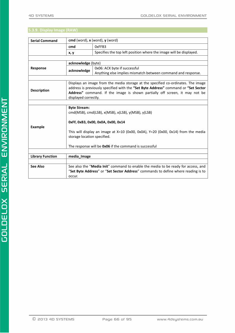
4D SYSTEMS GOLDELOX SERIAL ENVIRONMENT
© 2013 4D SYSTEMS Page 66 of 95 www.4dsystems.com.au
GOLD
ELO
X
SERIA
L E
NVIR
ONM
ENT
5.3.9. Display Image (RAW)
Serial Command cmd (word), x (word), y (word)
cmd 0xFFB3
x, y Specifies the top left position where the image will be displayed.
Response
acknowledge (byte)
acknowledge 0x06: ACK byte if successful Anything else implies mismatch between command and response.
Description
Displays an image from the media storage at the specified co-ordinates. The image address is previously specified with the “Set Byte Address” command or “Set Sector Address” command. If the image is shown partially off screen, it may not be displayed correctly.
Example
Byte Stream: cmd(MSB), cmd(LSB), x(MSB), x(LSB), y(MSB), y(LSB) 0xFF, 0xB3, 0x00, 0x0A, 0x00, 0x14 This will display an image at X=10 (0x00, 0x0A), Y=20 (0x00, 0x14) from the media storage location specified. The response will be 0x06 if the command is successful
Library Function media_Image
See Also See also the “Media Init” command to enable the media to be ready for access, and “Set Byte Address” or “Set Sector Address” commands to define where reading is to occur.

4D SYSTEMS GOLDELOX SERIAL ENVIRONMENT
© 2013 4D SYSTEMS Page 67 of 95 www.4dsystems.com.au
GOLD
ELO
X
SERIA
L E
NVIR
ONM
ENT
5.3.10. Display Video (RAW)
Serial Command cmd (word), x (word), y (word)
cmd 0xFFBB
x, y Specifies the top left position where the video clip will be displayed.
Response
acknowledge (byte)
acknowledge 0x06: ACK byte if successful Anything else implies mismatch between command and response.
Description
Displays a video clip from the media storage device at the specified co-ordinates. The video address location in the media is previously specified with the “Set Byte Address” or “Set Sector Address” commands. If the video is shown partially off screen, it may not be displayed correctly. Note that showing a video blocks all other processes until the video has finished showing. See the “Display Video Frame” command for alternatives.
Example
Byte Stream: cmd(MSB), cmd(LSB), x(MSB), x(LSB), y(MSB), y(LSB) 0xFF, 0xBB, 0x00, 0x0A, 0x00, 0x0A This will display a video clip at X=10 (0x00, 0x0A), Y=10 (0x00, 0x0A) from the media storage device location specified. The response will be 0x06 if the command is successful
Library Function media_Video
See Also See also the “Media Init” command to enable the media to be ready for access, and “Set Byte Address” or “Set Sector Address” commands to define where reading is to occur. See the “Display Video Frames” command for an alternative.

4D SYSTEMS GOLDELOX SERIAL ENVIRONMENT
© 2013 4D SYSTEMS Page 68 of 95 www.4dsystems.com.au
GOLD
ELO
X
SERIA
L E
NVIR
ONM
ENT
5.3.11. Display Video Frame (RAW)
Serial Command cmd (word), x (word), y (word), frameNumber (word)
cmd 0xFFBA
x, y Specifies the top left position of the video frame to be displayed.
frameNumber Specifies the required frame number to be displayed.
Response
acknowledge (byte)
acknowledge 0x06: ACK byte if successful Anything else implies mismatch between command and response.
Description
Displays a video from the media storage device at the specified co-ordinates. The video address is previously specified with the “Set Byte Address” command or “Set Sector Address” command. If the video is shown partially off it may not be displayed correctly. The frames can be shown in any order. This function gives you great flexibility for showing various icons from an image strip, as well as showing videos while doing other tasks
Example
Byte Stream: cmd(MSB), cmd(LSB), x(MSB), x(LSB), y(MSB), y(LSB), frameNumber(MSB), frameNumber(LSB) 0xFF, 0xBA, 0x00, 0x23, 0x00, 0x05, 0x00, 0x2D This will display frame number 45 (0x00, 0x2D) of the video clip stored at the address specified, and display it at location X=35 (0x00, 0x23), Y=5 (0x00, 0x05). The response will be 0x06 if the command is successful
Library Function media_VideoFrame
See Also See also the “Media Init” command to enable the media to be ready for access, and “Set Byte Address” or “Set Sector Address” commands to define where reading is to occur.

4D SYSTEMS GOLDELOX SERIAL ENVIRONMENT
© 2013 4D SYSTEMS Page 69 of 95 www.4dsystems.com.au
GOLD
ELO
X
SERIA
L E
NVIR
ONM
ENT
5.4. Memory Access Commands The following is a summary of the commands available to be used for Memory Access:
Byte Peek
Byte Poke
Word Peek
Word Poke

4D SYSTEMS GOLDELOX SERIAL ENVIRONMENT
© 2013 4D SYSTEMS Page 70 of 95 www.4dsystems.com.au
GOLD
ELO
X
SERIA
L E
NVIR
ONM
ENT
5.4.1. Byte Peek
Serial Command cmd (word), byteRegister (word)
cmd 0xFFF6
byteRegister Byte register address. EVE System Registers Memory Map for Byte registers is listed at the end of this document.
Response
acknowledge (byte), value (word)
acknowledge 0x06: ACK byte if successful Anything else implies mismatch between command and response.
value Register value in the LSB.
Description This command returns the EVE System Byte Register value in the lower byte.
Example
Byte Stream: cmd(MSB), cmd(LSB), byteRegister(MSB), byteRegister(LSB) 0xFF, 0xF6, 0x00, 0xA1 This will read and return the byte value from the Byte register address 161 (0x00 0xA1) that represents Current Screen Mode. The response will be 0x06, 0x00, 0x01 assuming the Screen Mode being set to Landscape Reverse.
Library Function peekB
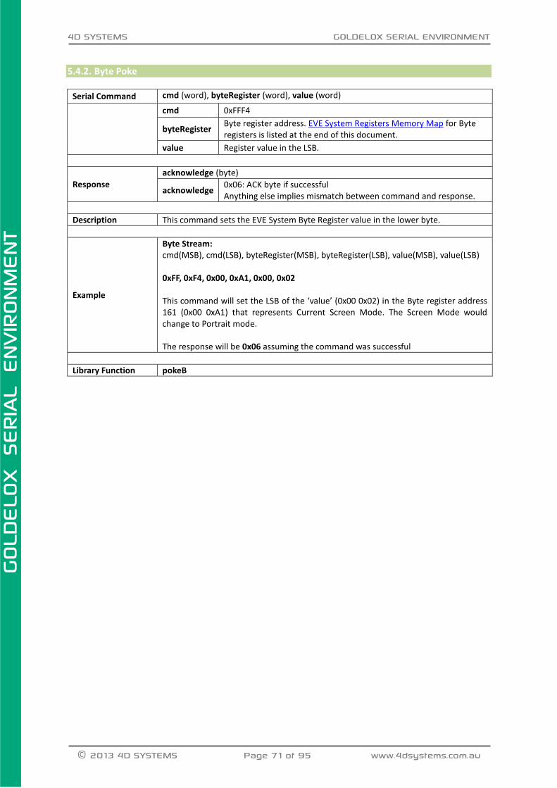
4D SYSTEMS GOLDELOX SERIAL ENVIRONMENT
© 2013 4D SYSTEMS Page 71 of 95 www.4dsystems.com.au
GOLD
ELO
X
SERIA
L E
NVIR
ONM
ENT
5.4.2. Byte Poke
Serial Command cmd (word), byteRegister (word), value (word)
cmd 0xFFF4
byteRegister Byte register address. EVE System Registers Memory Map for Byte registers is listed at the end of this document.
value Register value in the LSB.
Response
acknowledge (byte)
acknowledge 0x06: ACK byte if successful Anything else implies mismatch between command and response.
Description This command sets the EVE System Byte Register value in the lower byte.
Example
Byte Stream: cmd(MSB), cmd(LSB), byteRegister(MSB), byteRegister(LSB), value(MSB), value(LSB) 0xFF, 0xF4, 0x00, 0xA1, 0x00, 0x02 This command will set the LSB of the ‘value’ (0x00 0x02) in the Byte register address 161 (0x00 0xA1) that represents Current Screen Mode. The Screen Mode would change to Portrait mode. The response will be 0x06 assuming the command was successful
Library Function pokeB

4D SYSTEMS GOLDELOX SERIAL ENVIRONMENT
© 2013 4D SYSTEMS Page 72 of 95 www.4dsystems.com.au
GOLD
ELO
X
SERIA
L E
NVIR
ONM
ENT
5.4.3. Word Peek
Serial Command cmd (word), wordRegister (word)
cmd 0xFFF5
wordRegister Word register address. EVE System Registers Memory Map for Word registers is listed at the end of this document.
Response
acknowledge (byte), value (word)
acknowledge 0x06: ACK byte if successful Anything else implies mismatch between command and response.
value Register value.
Description This command returns the EVE System Word Register value.
Example
Byte Stream: cmd(MSB), cmd(LSB), wordRegister(MSB), wordRegister(LSB) 0xFF, 0xF5, 0x00, 0x68 This will read and return the word value from the word register address 104 (0x00 0x68) that represents Current X Origin. The response will be 0x06, 0x00, 0x00 assuming the current X Origin is set to 0.
Library Function peekW

4D SYSTEMS GOLDELOX SERIAL ENVIRONMENT
© 2013 4D SYSTEMS Page 73 of 95 www.4dsystems.com.au
GOLD
ELO
X
SERIA
L E
NVIR
ONM
ENT
5.4.4. Word Poke
Serial Command cmd (word), wordRegister (word), value (word)
cmd 0xFFF3
wordRegister Word register address. EVE System Registers Memory Map for Word registers is listed at the end of this document.
value Register value.
Response
acknowledge (byte)
acknowledge 0x06: ACK byte if successful Anything else implies mismatch between command and response.
Description This command sets the EVE System Word Register value.
Example
Byte Stream: cmd(MSB), cmd(LSB), WordRegister(MSB), WordRegister(LSB), value(MSB), value(LSB) 0xFF, 0xF3, 0x00, 0x68, 0x00, 0x0A This command will set the ‘value’ (0x00 0x0A) in the Word register address 104 (0x00 0x68) that represents Current X Origin. The Current X origin would change to 10 (0x00 0x0A). The response will be 0x06 assuming the command was successful
Library Function pokeW

4D SYSTEMS GOLDELOX SERIAL ENVIRONMENT
© 2013 4D SYSTEMS Page 74 of 95 www.4dsystems.com.au
GOLD
ELO
X
SERIA
L E
NVIR
ONM
ENT
5.5. GPIO Commands The following is a summary of the commands available to be used for GPIO:
Joystick

4D SYSTEMS GOLDELOX SERIAL ENVIRONMENT
© 2013 4D SYSTEMS Page 75 of 95 www.4dsystems.com.au
GOLD
ELO
X
SERIA
L E
NVIR
ONM
ENT
5.5.1. Joystick
Serial Command cmd (word)
cmd 0xFFD9
Response
acknowledge (byte), value (word)
acknowledge 0x06: ACK byte if successful Anything else implies mismatch between command and response.
value Returns the value of the Joystick position from 0 - 5(5 position switch implementation).
Description
This command will return the value of the joystick position. 0: RELEASED 1: UP 2:LEFT 3:DOWN 4:RIGHT 5:PRESS Note: The joystick input uses IO1 utilizing the A/D converter. Each switch is connected to junction of 2 resistors that form a unique voltage divider circuit. Refer to the GOLDELOX data sheet example schematics for the required resistor values. Note: The Joystick on 4Display-Shield-96, 4Display-Shield-128, 4Display-Shield-160 and 4Display-Shield-144 is not connected with the GPIOs of the Display Module on board. It is rather designed to connect with the Arduino Board directly. Please check the datasheets for further details on the above Shields.
Example
Byte Stream: cmd(MSB), cmd(LSB) 0xFF, 0xD9 If the IO1 is connected to the Joystick as shown in the above figure, the response will be 0x06 0x00 0x04 assuming the ‘RIGHT’ being activated through the joystick/switch.
Library Function joystick

4D SYSTEMS GOLDELOX SERIAL ENVIRONMENT
© 2013 4D SYSTEMS Page 76 of 95 www.4dsystems.com.au
GOLD
ELO
X
SERIA
L E
NVIR
ONM
ENT
5.6. Sound and Tune Commands The following is a summary of the commands available to be used for Sound and Tune:
Beep

4D SYSTEMS GOLDELOX SERIAL ENVIRONMENT
© 2013 4D SYSTEMS Page 77 of 95 www.4dsystems.com.au
GOLD
ELO
X
SERIA
L E
NVIR
ONM
ENT
5.6.1. Beep
Serial Command cmd (word), note (word), duration (word)
cmd 0xFFDA
note A value specifying the frequency of the note. Note could be between 0-64.
duration Specifies the time in milliseconds that the note will be played for.
Response
acknowledge (byte)
acknowledge 0x06: ACK byte if successful Anything else implies mismatch between command and response.
Description This command will produce a single musical note for the required duration through IO2.
Example
Byte Stream: cmd(MSB), cmd(LSB), note(MSB), note(LSB), duration(MSB), duration(LSB) 0xFF, 0xDA, 0x00, 0x2D, 0x03, 0xE8 This will play note 45 for 1 second. The response will be 0x06 assuming the command was successful
Library Function BeeP

4D SYSTEMS GOLDELOX SERIAL ENVIRONMENT
© 2013 4D SYSTEMS Page 78 of 95 www.4dsystems.com.au
GOLD
ELO
X
SERIA
L E
NVIR
ONM
ENT
5.7. Serial (UART) Communications Commands The following is a summary of the commands available to be used for Serial (UART) Communications:
Set Baud Rate

4D SYSTEMS GOLDELOX SERIAL ENVIRONMENT
© 2013 4D SYSTEMS Page 79 of 95 www.4dsystems.com.au
GOLD
ELO
X
SERIA
L E
NVIR
ONM
ENT
5.7.1. Set Baud Rate
Serial Command cmd (word), index (word)
cmd 0x000B
index
Specifies the baud rate index value.
index Required Baud Rate % Error Actual Baud Rate
27271 110 0.00% 110
9999 300 0.00% 300
4999 600 0.00% 600
2499 1200 0.00% 1200
1249 2400 0.00% 2400
624 4800 0.00% 4800
312 9600 -0.16% 9585
207 14400 0.16% 14423
155 19200 0.16% 19231
95 31250 0.00% 31250
77 38400 0.16% 38462
53 56000 -0.79% 55556
51 57600 0.16% 57692
25 115200 0.16% 115385
22 128000 1.90% 130435
11 256000 -2.34% 250000
10 300000 -9.09% 272727
8 375000 -11.11% 333333
6 500000 -14.29% 428571
4 600000 0.00% 600000
Response
acknowledge (byte)
acknowledge 0x06: ACK byte if successful Anything else implies mismatch between command and response.
Description The Set Baud Rate command is used to set the required baud rate. To set the default
baud rate, please refer to the instructions in Chapter 2.
Example
Byte Stream: cmd(MSB), cmd(LSB), index(MSB), index(LSB) 0x00, 0x0B, 0x00, 0x0A This will set the baud rate to be 300000, which is Index 10 (0x00, 0x0A) The response will be 0x06 at the new baud rate set, 100ms after the command is sent
Library Function setbaudWait
4D SYSTEMS GOLDELOX SERIAL ENVIRONMENT
© 2013 4D SYSTEMS Page 80 of 95 www.4dsystems.com.au
GOLD
ELO
X
SERIA
L E
NVIR
ONM
ENT
5.8. Image Control Commands The following is a summary of the commands available to be used for Image Control:
Blit Com to Display
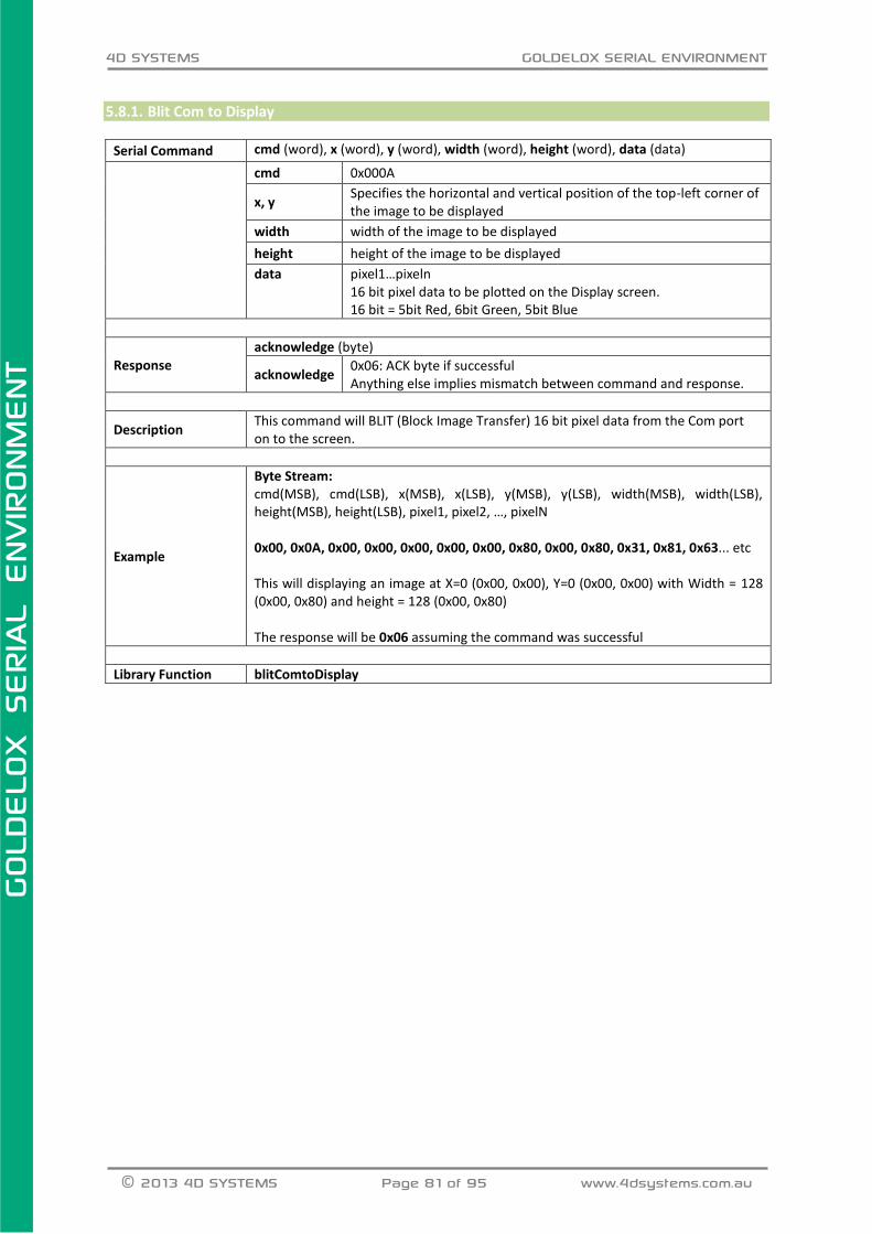
4D SYSTEMS GOLDELOX SERIAL ENVIRONMENT
© 2013 4D SYSTEMS Page 81 of 95 www.4dsystems.com.au
GOLD
ELO
X
SERIA
L E
NVIR
ONM
ENT
5.8.1. Blit Com to Display
Serial Command cmd (word), x (word), y (word), width (word), height (word), data (data)
cmd 0x000A
x, y Specifies the horizontal and vertical position of the top-left corner of the image to be displayed
width width of the image to be displayed
height height of the image to be displayed
data pixel1…pixeln 16 bit pixel data to be plotted on the Display screen. 16 bit = 5bit Red, 6bit Green, 5bit Blue
Response
acknowledge (byte)
acknowledge 0x06: ACK byte if successful Anything else implies mismatch between command and response.
Description This command will BLIT (Block Image Transfer) 16 bit pixel data from the Com port on to the screen.
Example
Byte Stream: cmd(MSB), cmd(LSB), x(MSB), x(LSB), y(MSB), y(LSB), width(MSB), width(LSB), height(MSB), height(LSB), pixel1, pixel2, …, pixelN 0x00, 0x0A, 0x00, 0x00, 0x00, 0x00, 0x00, 0x80, 0x00, 0x80, 0x31, 0x81, 0x63... etc This will displaying an image at X=0 (0x00, 0x00), Y=0 (0x00, 0x00) with Width = 128 (0x00, 0x80) and height = 128 (0x00, 0x80) The response will be 0x06 assuming the command was successful
Library Function blitComtoDisplay

4D SYSTEMS GOLDELOX SERIAL ENVIRONMENT
© 2013 4D SYSTEMS Page 82 of 95 www.4dsystems.com.au
GOLD
ELO
X
SERIA
L E
NVIR
ONM
ENT
5.9. System Commands The following is a summary of the commands available to be used for System:
Get Display Model
Get SPE Version
Get PmmC Version
Screen Saver Timeout
Screen Saver Speed
Screen Saver Mode

4D SYSTEMS GOLDELOX SERIAL ENVIRONMENT
© 2013 4D SYSTEMS Page 83 of 95 www.4dsystems.com.au
GOLD
ELO
X
SERIA
L E
NVIR
ONM
ENT
5.9.1. Get Display Model
Serial Command cmd (word)
cmd 0x0007
Response
acknowledge (byte), model (string)
acknowledge 0x06: ACK byte if successful Anything else implies mismatch between command and response.
count Number of characters in the model name to return
model Display Module’s model name. Without NULL terminator.
Description Returns the Display Model in the form of a string without Null terminator.
Example
Byte Stream: cmd(MSB), cmd(LSB) 0x00, 0x07 This will request the display to return its model name as a string of characters without the NULL. The response will be 0x06, 0x00, 0x0C, 0x75 0x4F 0x4C 0x45 0x44 0x2D 0x31 0x36 0x30 0x2D 0x47 0x32 assuming the command was successful and the display returned 12 characters (0x00, 0x0C) and the display model was “uOLED-160-G2” (0x75 0x4F 0x4C 0x45 0x44 0x2D 0x31 0x36 0x30 0x2D 0x47 0x32)
Library Function sys_GetModel

4D SYSTEMS GOLDELOX SERIAL ENVIRONMENT
© 2013 4D SYSTEMS Page 84 of 95 www.4dsystems.com.au
GOLD
ELO
X
SERIA
L E
NVIR
ONM
ENT
5.9.2. Get SPE Version
Serial Command cmd (word)
cmd 0x0008
Response
acknowledge (byte), version (word)
acknowledge 0x06: ACK byte if successful Anything else implies mismatch between command and response.
version SPE Version installed on the module.
Description Returns the SPE Version installed on the module.
Example
Byte Stream: cmd(MSB), cmd(LSB) 0x00, 0x08 This will return the version of the SPE Application loaded into the display The response will be 0x06, 0x01, 0x00 assuming the command was successful and the version of the SPE Application was 256 (0x01, 0x00)
Library Function sys_GetVersion

4D SYSTEMS GOLDELOX SERIAL ENVIRONMENT
© 2013 4D SYSTEMS Page 85 of 95 www.4dsystems.com.au
GOLD
ELO
X
SERIA
L E
NVIR
ONM
ENT
5.9.3. Get PmmC Version
Serial Command cmd (word)
cmd 0x0009
Response
acknowledge (byte), version (word)
acknowledge 0x06: ACK byte if successful Anything else implies mismatch between command and response.
version PmmC Version installed on the module.
Description Returns the PmmC Version installed on the module.
Example
Byte Stream: cmd(MSB), cmd(LSB) 0x00, 0x09 This will return the version of the PmmC loaded into the display The response will be 0x06, 0x02, 0x03 assuming the command was successful and the PmmC loaded was version 515 (0x02, 0x03) which represents Rev23
Library Function sys_GetPmmC

4D SYSTEMS GOLDELOX SERIAL ENVIRONMENT
© 2013 4D SYSTEMS Page 86 of 95 www.4dsystems.com.au
GOLD
ELO
X
SERIA
L E
NVIR
ONM
ENT
5.9.4. Screen Saver Timeout
Serial Command cmd (word), timeout(word)
cmd 0x000C
timeout Specifies the screen saver timeout in milliseconds. Timeout value could be 1-65535. 0 disables the screen saver.
Response
acknowledge (byte)
acknowledge 0x06: ACK byte if successful Anything else implies mismatch between command and response.
Description
This command will set the screen saver Timeout. 0 is set to disable the screen saver. Default screen saver timeout settings could be adjusted as shown in section 2.2. Note: This feature is display dependent. Not all the display screens offer Screen Saver feature. Such as, uLCD-144-G2 does not support Screen Saver.
Example
Byte Stream: cmd(MSB), cmd(LSB), timeout(MSB), timeout(LSB) 0x00, 0x0C, 0x03, 0xE8 This will set the screen saver timeout to 1 second. Where (0x03 0xE8) is 1000msec. The response will be 0x06 assuming the command was successful
Library Function SSTimeout

4D SYSTEMS GOLDELOX SERIAL ENVIRONMENT
© 2013 4D SYSTEMS Page 87 of 95 www.4dsystems.com.au
GOLD
ELO
X
SERIA
L E
NVIR
ONM
ENT
5.9.5. Screen Saver Speed
Serial Command cmd (word), speed(word)
cmd 0x000D
speed
Specifies the screen saver speed. Speed values are different for different Display Modules. uLCD-144-G2: N/A uOLED-96-G2: 0-3 (Fastest-Slowest) uOLED-128-G2: 0-3 (Fastest-Slowest) uOLED-160-G2: 0-255 (Fastest-Slowest) uTOLED-20-G2: 1-16 (Fastest-Slowest)
Response acknowledge (byte)
acknowledge 0x06: ACK byte if successful Anything else implies mismatch between command and response.
Description
This command will set the screen saver Speed. Default screen saver speed settings could be adjusted as shown in section 2.2. Note: This feature is display dependent. Not all the display screens offer Screen Saver feature.
Example
Byte Stream: cmd(MSB), cmd(LSB), speed(MSB), speed(LSB) 0x00, 0x0D, 0x00, 0x00 This will set the screen saver speed to maximum. The response will be 0x06 assuming the command was successful
Library Function SSTimeout

4D SYSTEMS GOLDELOX SERIAL ENVIRONMENT
© 2013 4D SYSTEMS Page 88 of 95 www.4dsystems.com.au
GOLD
ELO
X
SERIA
L E
NVIR
ONM
ENT
5.9.6. Screen Saver Mode
Serial Command cmd (word), mode(word)
cmd 0x000E
mode
Specifies the screen saver scroll direction. ‘mode’ values are different for different display modules. uLCD-144-G2: N/A uOLED-96-G2: N/A uOLED-128-G2: N/A uOLED-160-G2: 0-Up, 1-Down, 2-Left, 3-Right uTOLED-20-G2: 0-Left, 1-Right, 3-Down, 7-Up 4-Left/Down, 5-Down/Right, 8-Top/Left, 9-Top/Right
Response
acknowledge (byte)
acknowledge 0x06: ACK byte if successful Anything else implies mismatch between command and response.
Description
This command will set the screen saver scroll direction. There could be no screen saver supported in which case the screen wouldn’t have any effect from this command. Or, there could be 2 directional or 4 directional scroll features available on a particular display screen. Note: This feature is display dependent. Not all the display screens offer Screen Saver feature. Default screen saver speed settings could be adjusted as shown in section 2.2.
Example 1
Byte Stream: cmd(MSB), cmd(LSB), mode(MSB), mode(LSB) 0x00, 0x0E, 0x00, 0x00 This will set the screen saver scroll direction to ‘UP’ on a uOLED-128-G2 module. The response will be 0x06 assuming the command was successful
Example 2
Byte Stream: cmd(MSB), cmd(LSB), mode(MSB), mode(LSB) 0x00, 0x0E, 0x00, 0x00 This will set the screen saver scroll direction to ‘RIGHT’ on a uOLED-160-G2 module. The response will be 0x06 assuming the command was successful
Library Function SSMode

4D SYSTEMS GOLDELOX SERIAL ENVIRONMENT
© 2013 4D SYSTEMS Page 89 of 95 www.4dsystems.com.au
GOLD
ELO
X
SERIA
L E
NVIR
ONM
ENT
6. GOLDELOX EVE System Registers Memory Map
The following tables outline in detail the GOLDELOX system registers and flags.
Table 6.1: BYTE-Size Registers Memory Map
LABEL ADDRESS
USAGE SIZE *NOTES DEC HEX
VX1 128 0x80 display hardware GRAM x1 pos BYTE SYSTEM (R/O)
VY1 129 0x81 display hardware GRAM y1 pos BYTE SYSTEM (R/O)
VX2 130 0x82 display hardware GRAM x2 pos BYTE SYSTEM (R/O)
VY2 131 0x83 display hardware GRAM y2 pos BYTE SYSTEM (R/O)
SYS_X_MAX 132 0x84 display hardware X res-1 BYTE SYSTEM (R/O)
SYS_Y_MAX 133 0x85 display hardware Y res-1 BYTE SYSTEM (R/O)
WRITE_GRAM_REG 134 0x86 display GRAM write address BYTE SYSTEM (R/O)
READ_GRAM_REG 135 0x87 display GRAM read address BYTE SYSTEM (R/O)
IMAGE_WIDTH 136 0x88 loaded image/animation width BYTE SYSTEM (R/O)
IMAGE_HEIGHT 137 0x89 loaded image/animation height BYTE SYSTEM (R/O)
IMAGE_DELAY 138 0x8A frame delay (if animation) BYTE USER
IMAGE_MODE 139 0x8B image/animation colour mode BYTE SYSTEM (R/O)
CLIP_LEFT_POS 140 0x8C left clipping point setting BYTE USER
CLIP_TOP_POS 141 0x8D top clipping point setting BYTE USER
CLIP_RIGHT_POS 142 0x8E right clipping point setting BYTE USER
CLIP_BOTTOM_POS 143 0x8F bottom clipping point setting BYTE USER
CLIP_LEFT 144 0x90 left clipping point active BYTE USER
CLIP_TOP 145 0x91 top clipping point active BYTE USER
CLIP_RIGHT 146 0x92 right clipping point active BYTE USER
CLIP_BOTTOM 147 0x93 bottom clipping point active BYTE USER
FONT_TYPE 148 0x94 0 = fixed, 1 = proportional BYTE SYSTEM (R/O)
FONT_MAX 149 0x95 number of chars in font set BYTE SYSTEM (R/O)
FONT_OFFSET 150 0x96 ASCII offset (usually 0x20) BYTE SYSTEM (R/O)
FONT_WIDTH 151 0x97 width of font (pixel units) BYTE SYSTEM (R/O)
FONT_HEIGHT 152 0x98 height of font (pixel units) BYTE SYSTEM (R/O)
TEXT_XMAG 153 0x99 text width magnification BYTE USER
TEXT_YMAG 154 0x9A text height magnification BYTE USER
TEXT_MARGIN 155 0x9B text place holder for CR BYTE SYSTEM (R/O)
TEXT_DELAY 156 0x9C text delay effect (0-255msec) BYTE USER
TEXT_X_GAP 157 0x9D X pixel gap between chars BYTE USER
TEXT_Y_GAP 158 0x9E Y pixel gap between chars BYTE USER
GFX_XMAX 159 0x9F width of current orientation BYTE SYSTEM (R/O)

4D SYSTEMS GOLDELOX SERIAL ENVIRONMENT
© 2013 4D SYSTEMS Page 90 of 95 www.4dsystems.com.au
GOLD
ELO
X
SERIA
L E
NVIR
ONM
ENT
GFX_YMAX 160 0xA0 height of current orientation BYTE SYSTEM (R/O)
GFX_SCREENMODE 161 0xA1 Current screen mode (0-3) BYTE SYSTEM (R/O)
reserved 162-165
0xA2-0xA5
reserved BYTE SYSTEM (R/O)
* NOTES:
SYSTEM SYSTEM registers are maintained by internal system functions and should not be written to. They should only ever be read. DO NOT WRITE to these registers.
USER USER registers are read/write (R/W) registers used to alter the system behaviour. Refer to the individual functions for information on the interaction with these registers.
These registers are accessible with peekB and pokeB functions.

4D SYSTEMS GOLDELOX SERIAL ENVIRONMENT
© 2013 4D SYSTEMS Page 91 of 95 www.4dsystems.com.au
GOLD
ELO
X
SERIA
L E
NVIR
ONM
ENT
Table 6.2: WORD-Size Registers Memory Map
LABEL ADDRESS
USAGE SIZE *NOTES DEC HEX
SYS_OVERFLOW 83 0x53 16bit overflow register WORD USER
SYS_COLOUR 84 0x54 internal variable for colour WORD SYSTEM
SYS_RETVAL 85 0x55 return value of last function WORD SYSTEM
GFX_BACK_COLOUR 86 0x56 screen background colour WORD USER
GFX_OBJECT_COLOUR 87 0x57 graphics object colour WORD USER
GFX_TEXT_COLOUR 88 0x58 text foreground colour WORD USER
GFX_TEXT_BGCOLOUR 89 0x59 text background colour WORD USER
GFX_OUTLINE_COLOUR 90 0x5A circle/rectangle outline WORD USER
GFX_LINE_PATTERN 91 0x5B line draw tessellation WORD USER
IMG_PIXEL_COUNT 92 0x5C count of pixels in image WORD SYSTEM
IMG_FRAME_COUNT 93 0x5D count of frames in animation WORD SYSTEM
MEDIA_HEAD 94 0x5E media sector head position WORD SYSTEM
SYS_OUTSTREAM 95 0x5F Output stream handle WORD SYSTEM
GFX_LEFT 96 0x60 image left real point WORD SYSTEM
GFX_TOP 97 0x61 image top real point WORD SYSTEM
GFX_RIGHT 98 0x62 image right real point WORD SYSTEM
GFX_BOTTOM 99 0x63 image bottom real point WORD SYSTEM
GFX_X1 100 0x64 image left clipped point WORD SYSTEM
GFX_Y1 101 0x65 image top clipped point WORD SYSTEM
GFX_X2 102 0x66 image right clipped point WORD SYSTEM
GFX_Y2 103 0x67 image bottom clipped point WORD SYSTEM
GFX_X_ORG 104 0x68 current X origin WORD USER
GFX_Y_ORG 105 0x69 current Y origin WORD USER
RANDOM_LO 106 0x6A random generator LO word WORD SYSTEM
RANDOM_HI 107 0x6B random generator HI word WORD SYSTEM
MEDIA_ADDR_LO 108 0x6C media byte address LO WORD SYSTEM
MEDIA_ADDR_HI 109 0x6D media byte address HI WORD SYSTEM
SECTOR_ADDR_LO 110 0x6E media sector address LO WORD SYSTEM
SECTOR_ADDR_HI 111 0x6F media sector address HI WORD SYSTEM
SYSTEM_TIMER_LO 112 0x70 1msec system timer LO word WORD USER
SYSTEM_TIMER_HI 113 0x71 1msec system timer HI word WORD USER
TIMER0 114 0x72 1msec user timer 0 WORD USER
TIMER1 115 0x73 1msec user timer 1 WORD USER
TIMER2 116 0x74 1msec user timer 2 WORD USER
TIMER3 117 0x75 1msec user timer 3 WORD USER
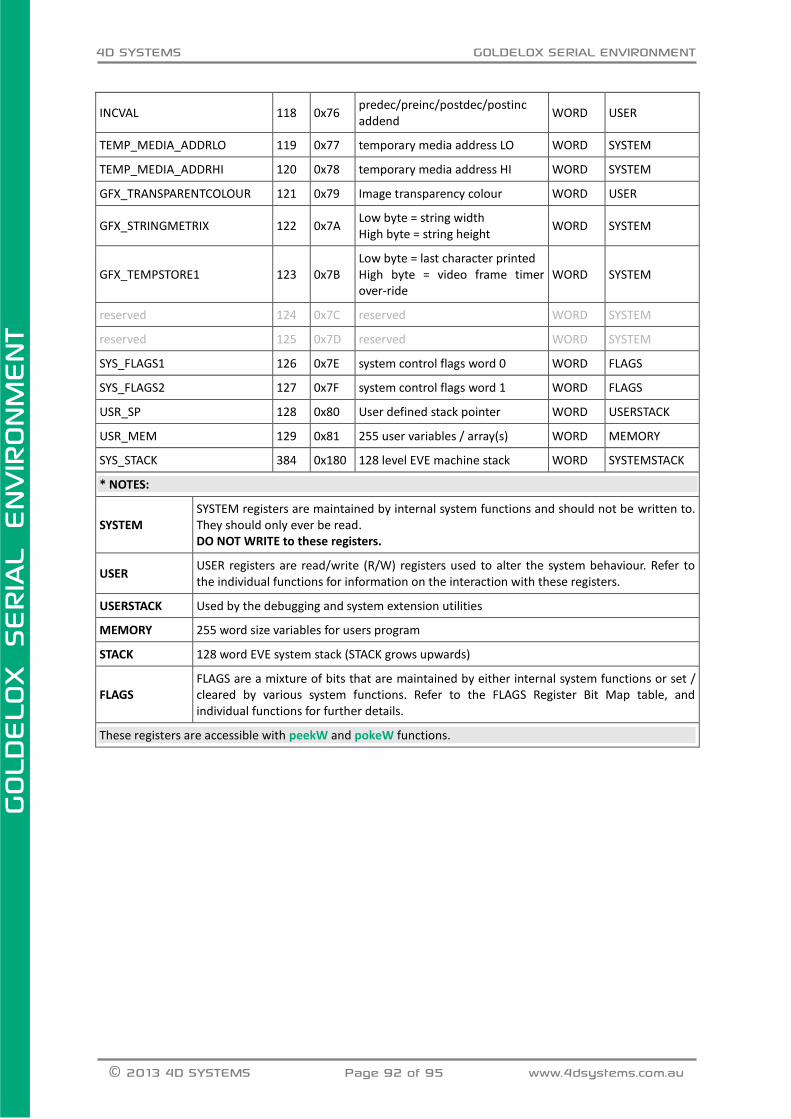
4D SYSTEMS GOLDELOX SERIAL ENVIRONMENT
© 2013 4D SYSTEMS Page 92 of 95 www.4dsystems.com.au
GOLD
ELO
X
SERIA
L E
NVIR
ONM
ENT
INCVAL 118 0x76 predec/preinc/postdec/postinc addend
WORD USER
TEMP_MEDIA_ADDRLO 119 0x77 temporary media address LO WORD SYSTEM
TEMP_MEDIA_ADDRHI 120 0x78 temporary media address HI WORD SYSTEM
GFX_TRANSPARENTCOLOUR 121 0x79 Image transparency colour WORD USER
GFX_STRINGMETRIX 122 0x7A Low byte = string width High byte = string height
WORD SYSTEM
GFX_TEMPSTORE1 123 0x7B Low byte = last character printed High byte = video frame timer over-ride
WORD SYSTEM
reserved 124 0x7C reserved WORD SYSTEM
reserved 125 0x7D reserved WORD SYSTEM
SYS_FLAGS1 126 0x7E system control flags word 0 WORD FLAGS
SYS_FLAGS2 127 0x7F system control flags word 1 WORD FLAGS
USR_SP 128 0x80 User defined stack pointer WORD USERSTACK
USR_MEM 129 0x81 255 user variables / array(s) WORD MEMORY
SYS_STACK 384 0x180 128 level EVE machine stack WORD SYSTEMSTACK
* NOTES:
SYSTEM SYSTEM registers are maintained by internal system functions and should not be written to. They should only ever be read. DO NOT WRITE to these registers.
USER USER registers are read/write (R/W) registers used to alter the system behaviour. Refer to the individual functions for information on the interaction with these registers.
USERSTACK Used by the debugging and system extension utilities
MEMORY 255 word size variables for users program
STACK 128 word EVE system stack (STACK grows upwards)
FLAGS FLAGS are a mixture of bits that are maintained by either internal system functions or set / cleared by various system functions. Refer to the FLAGS Register Bit Map table, and individual functions for further details.
These registers are accessible with peekW and pokeW functions.

4D SYSTEMS GOLDELOX SERIAL ENVIRONMENT
© 2013 4D SYSTEMS Page 93 of 95 www.4dsystems.com.au
GOLD
ELO
X
SERIA
L E
NVIR
ONM
ENT
Table 6.3: FLAG Registers Bit Map
REGISTER ADDRESS
NAME USAGE *NOTES VALUE DEC HEX
SYS_FLAGS1 126 0x7E * denotes auto reset
Bit 0 _STREAMLOCK Used internally SYSTEM 0x0001
Bit 1 _PENSIZE Object, 0 = solid, 1 = outline SYSTEM 0x0002
Bit 2 _OPACITY Text, 0 = transparent, 1 = opaque SYSTEM 0x0004
Bit 3 _OUTLINED box/circle outline 0 = off, 1 = on SYSTEM 0x0008
Bit 4 _BOLD * text, 0 = normal, 1 = bold SYSTEM 0x0010
Bit 5 _ITALIC * Text, 0 = normal, 1 = italic SYSTEM 0x0020
Bit 6 _INVERSE * Text, 0 = normal, 1 = inverse SYSTEM 0x0040
Bit 7 _UNDERLINED * Text, 0 = normal, 1 = underlined SYSTEM 0x0080
Bit 8 _CLIPPING 0 = clipping off, 1 = clipping on SYSTEM 0x0100
Bit 9 _STRMODE Used internally SYSTEM 0x0200
Bit 10 _SERMODE Used internally SYSTEM 0x0400
Bit 11 _TXTMODE Used internally SYSTEM 0x0800
Bit 12 _MEDIAMODE Used internally SYSTEM 0x1000
Bit 13 _PATTERNED Used internally SYSTEM 0x2000
Bit 14 _COLOUR8 Display mode, 0 = 16bit, 1 = 8bit SYSTEM 0x4000
Bit 15 _MEDIAFONT 0 = internal font, 1 = media font SYSTEM 0x8000
SYS_FLAGS2 127 0x7F
Bit 0 _MEDIA_INSTALLED SD/SDHC or FLASH is detected/active
SYSTEM 0x0001
Bit 1 _MEDIA_TYPE 0 = SD/SDHC, 1 = FLASH chip SYSTEM 0x0002
Bit 2 _MEDIA_READ 1 = MEDIA read in progress SYSTEM 0x0004
Bit 3 _MEDIA_WRITE 1 = MEDIA write in progress SYSTEM 0x0008
Bit 4 _OW_PIN 0 = IO1, 1 = IO2 (Dallas OW Pin) SYSTEM 0x0010
Bit 5 _PTR_TYPE Used internally SYSTEM 0x0020
Bit 6 _TEMP1 Used internally SYSTEM 0x0040
Bit 7 _TEMP2 Used internally SYSTEM 0x0080
Bit 8 _RUNMODE 1 = running pcode from media SYSTEM 0x0100
Bit 9 _SIGNED 0 = number printed '-' prepend SYSTEM 0x0200
Bit 10 _RUNFLAG 1 = EVE processor is running SYSTEM 0x0400
Bit 11 _SINGLESTEP 1 = set breakpoint for debugger SYSTEM 0x0800
Bit 12 _COMMINT 1 = buffered coms active SYSTEM 0x1000
Bit 13 _DUMMY16 1 = display needs 16bit dummy SYSTEM 0x2000
Bit 14 _DISP16 1 = display is 16bit interface SYSTEM 0x4000
Bit 15 _PROPFONT 1 = current font is proportional SYSTEM 0x8000

4D SYSTEMS GOLDELOX SERIAL ENVIRONMENT
© 2013 4D SYSTEMS Page 94 of 95 www.4dsystems.com.au
GOLD
ELO
X
SERIA
L E
NVIR
ONM
ENT
7. Revision History
Revision History
Revision Revision Content Revision Date
1.0 First Release 01/02/2013
1.1 Added character limit information to the Put String command 22/02/2013
1.2 Fixed Set Font command, which was incorrect 21/03/2013
1.3 Fixed Set Baud Rate index values, which were incorrect 22/03/2013

4D SYSTEMS GOLDELOX SERIAL ENVIRONMENT
© 2013 4D SYSTEMS Page 95 of 95 www.4dsystems.com.au
GOLD
ELO
X
SERIA
L E
NVIR
ONM
ENT
8. Legal Notice Proprietary Information The information contained in this document is the property of 4D Systems Pty. Ltd. and may be the subject of patents pending or granted, and must not be copied or disclosed without prior written permission. 4D Systems endeavours to ensure that the information in this document is correct and fairly stated but does not accept liability for any error or omission. The development of 4D Systems products and services is continuous and published information may not be up to date. It is important to check the current position with 4D Systems. 4D Systems reserves the right to modify, update or makes changes to Specifications or written material without prior notice at any time. All trademarks belong to their respective owners and are recognised and acknowledged. Disclaimer of Warranties & Limitation of Liability 4D Systems makes no warranty, either expressed or implied with respect to any product, and specifically disclaims all other warranties, including, without limitation, warranties for merchantability, non-infringement and fitness for any particular purpose. Information contained in this publication regarding device applications and the like is provided only for your convenience and may be superseded by updates. It is your responsibility to ensure that your application meets with your specifications. In no event shall 4D Systems be liable to the buyer or to any third party for any indirect, incidental, special, consequential, punitive or exemplary damages (including without limitation lost profits, lost savings, or loss of business opportunity) arising out of or relating to any product or service provided or to be provided by 4D Systems, or the use or inability to use the same, even if 4D Systems has been advised of the possibility of such damages. 4D Systems products are not fault tolerant nor designed, manufactured or intended for use or resale as on line control equipment in hazardous environments requiring fail – safe performance, such as in the operation of nuclear facilities, aircraft navigation or communication systems, air traffic control, direct life support machines or weapons systems in which the failure of the product could lead directly to death, personal injury or severe physical or environmental damage (‘High Risk Activities’). 4D Systems and its suppliers specifically disclaim any expressed or implied warranty of fitness for High Risk Activities. Use of 4D Systems’ products and devices in 'High Risk Activities' and in any other application is entirely at the buyer’s risk, and the buyer agrees to defend, indemnify and hold harmless 4D Systems from any and all damages, claims, suits, or expenses resulting from such use. No licenses are conveyed, implicitly or otherwise, under any 4D Systems intellectual property rights.
9. Contact Information
For Technical Support: [email protected]
For Sales Support: [email protected]
Website: www.4dsystems.com.au
Copyright 4D Systems Pty. Ltd. 2000-2013.