4a. lighting 2014
TRANSCRIPT
2/18/14
1
CE 563 Airport Design
Reference: AC 150/5340-‐30G
Mark the airport Civil airports
12 flashes per minute White-‐green, land White-‐yellow, water
Military airports 18 flashes per minute Double white-‐green, land Double white-‐yellow, water
9/29/2011 AC 150/5340-30F Appendix 1
189
F igure 72. Typical Tubular Steel Beacon Tower .
L -8 0 2 A A IR P O R T R O T A T IN G B E A C O N
O P T IO N A L 8 ' L O N GL IG H T N IN G R O D S (3 )
5 2 '- '6 "N O M IN A L B E A C O N
M O U N T IN G H E IG H T
5 1 '-0 "N O M IN A L
7 ' Ø B E A C O N B A S K E T
H A N D H O L E 1 8 " A B O V E B A S E P L A T E A N O T H E R A T2 5 ' A B O V E B A S E P L A T E L E V E L
B E A C O N P O L E F O U N D A T IO N
1 2 "
C L IM B IN G R U N G S
C L IM B E R S A F E T Y D E V IC E (T O P )
C L IM B E R S A F E T Y D E V IC E (B O T T O M )
2 4 "
B E A C O N P O L E P A IN T IN G D E T A IL( IT E M S N O T S H O W N
O M IT T E D F O R C L A R IT Y )
7 '-6 " A P P R O X O R A N G E S T R IP E
7 '-6 " A P P R O XW H IT E S T R IP E
All obstructions are identified with lights Red ▪ Fixed ▪ Flashing ▪ Rotating

2/18/14
2
Locate field, properly align aircraft Correct runway Roll, pitch, yaw Height Alignment Glide slope
Some type of ground reference is required Approach Lighting System with sequenced Flashing lights (ALSF-‐1, ALSF-‐2)
Medium-‐intensity Approach Lighting System w/ Runway alignment indicators (MALSR)
Medium-‐intensity Approach Lighting System with sequential Flashers (MALSF)
Medium-‐intensity Approach Lighting System (MALS)
AC 150/5340-30F 9/29/2011 Appendix 1
194
F igure 76. Typical Layout for M A LSF .
1 . T H E O P T IM U M L O C A T IO N O F T H E A P P R O A C H L IG H T S IS IN A H O R IZ O N T A L P L A N E A T R U N W A Y E N D E L E V A T IO N . P R O V ID E A T L E A S T T H R E E C O N S E C U T IV E L IG H T B A R S T A T IO N S IN A S L O P IN G S E G M E N T O F T H E S Y S T E M . T H E S L O P IN G S E G M E N T M A Y S T A R T A T T H E F IR S T L IG H T B A R A N D E X T E N D T O T H E E N D O F T H E S Y S T E M O R M A Y B E P R E C E D E D B Y A H O R IZ O N T A L S E G M E N T O R F O L L O W E D B Y E IT H E R A H O R IZ O N T A L O R N E G A T IV E S L O P IN G S E G M E N T .
2 . A M A X IM U M 2 P E R C E N T U P W A R D L O N G IT U D IN A L S L O P E T O L E R A N C E M A Y B E U S E D T O R A IS E T H E L IG H T P A T T E R N A B O V E O B J E C T S W IT H IN IT S A R E A .
3 . A M A X IM U M 1 P E R C E N T D O W N W A R D L O N G IT U D IN A L S L O P E T O L E R A N C E M A Y B E U S E D T O R E D U C E T H E H E IG H T O F S U P P O R T IN G S T R U C T U R E S .
4 . A L L S T E A D Y B U R N IN G A N D F L A S H IN G L IG H T S A R E A IM E D W IT H T H E IR B E A M A X E S P A R A L L E L T O T H E R U N W A Y C E N T E R L IN E A N D IN T E R C E P T IN G A N A S S U M E D 3 ° G L ID E S L O P E (IN T E R C E P T IN G T H E R U N W A Y 1 0 0 0 F E E T F R O M T H E L A N D IN G T H R E S H O L D ) A T A H O R IZ O N T A L D IS T A N C E O F 1 6 0 0 F E E T IN A D V A N C E O F T H E L IG H T .
N O T E S :
5 . A L L O B S T R U C T IO N S A S D E T E R M IN E D B Y A P P L IC A B L E C R IT E R IA (1 4 C F R P A R T 7 7 ) F O R D E T E R M IN IN G O B S T R U C T IO N S T O A IR N A V IG A T IO N A R E L IG H T E D A N D M A R K E D A S R E Q U IR E D .
6 . IN T E N S IT Y C O N T R O L IS P R O V ID E D F O R T H E S T E A D Y B U R N IN G L IG H T S .
7 . T H E T H R E E F L A S H IN G L IG H T S F L A S H IN S E Q U E N C E .
8 . T H E M IN IM U M L A N D R E Q U IR E M E N T S F O R M A L S F IS A N A R E A 1 6 0 0 ' IN L E N G T H B Y 4 0 0 ' W ID E .
9 . P R O V ID E A C L E A R L IN E O F S IG H T T O A L L L IG H T S O F T H E S Y S T E M F R O M A N Y P O IN T O N A S U R F A C E 1 /2 ° B E L O W A 3 ° G L ID E P A T H , IN T E R S E C T IN G T H E R U N W A Y 1 0 0 0 ' F R O M T H E L A N D IN G T H R E S H O L D .
(F O R M A L S F O N L Y )
1 0 '
7 C E N T E R L IN EB A R S @2 0 0 '± 2 0 '
S P A C IN G
1 0 '
+ 1 0 0 '-0 '
+ 1 0 0 '-0 '
+ 1 0 0 '-0 '2 0 0 '
+ 1 '-0 '
1 0 . T H R E S H O L D L IG H T S A R E U N ID IR E C T IO N A L F A C IN G A P P R O A C H .
1 0 ' M A XR U N W A Y T H R E S H O L D
S Y M B O L S :
S T E A D Y B U R N IN G L IG H T , G R E E N S T E A D Y B U R N IN G L IG H T , W H IT E S E Q U E N C E D F L A S H IN G L IG H T
R U N W A Y CL
2 8 ' 2 8 '
1 4 0 0 '
1 0 0 0 '
1 0 ' 1 0 '

2/18/14
3
Visual Approach Slope Indicator (VASI)
Precision-‐Approach Path Indicator (PAPI) AC 150/5340-30F 9/29/2011 Appendix 1
198
(1) Above correct glide path All lamps white.
(1) Above the correct glide path: 2 white lamps.
(2) Slightly above correct glide path. 3 white, 1 red.
(3) On the correct glide path. Two white, two red.
(2) On the correct glide path: 1 white, 1 red.
(4) Slightly below the correct glide path. 1 white, 3 red.
(5) Below the correct glide path: All red.
(3) Below the correct glide path: Two red lamps.
Type L-880 Type L-881
N O T E : The PAPI is a system of either four or two identical light units placed on the left of the runway in a line perpendicular to the centerline. The boxes are positioned and aimed to produce the visual signal shown above.
F igure 80. PAPI Signal Presentation.
10
10
10
10
10
10
10
10
AC 150/5340-30F 9/29/2011 Appendix 1
198
(1) Above correct glide path All lamps white.
(1) Above the correct glide path: 2 white lamps.
(2) Slightly above correct glide path. 3 white, 1 red.
(3) On the correct glide path. Two white, two red.
(2) On the correct glide path: 1 white, 1 red.
(4) Slightly below the correct glide path. 1 white, 3 red.
(5) Below the correct glide path: All red.
(3) Below the correct glide path: Two red lamps.
Type L-880 Type L-881
N O T E : The PAPI is a system of either four or two identical light units placed on the left of the runway in a line perpendicular to the centerline. The boxes are positioned and aimed to produce the visual signal shown above.
F igure 80. PAPI Signal Presentation.
10
10
10
10
10
10
10
10
High intensity (HIRL) Precision instrument runways
Medium intensity (MIRL) Visual runways at larger airports Non-‐precision instrument runways
Low intensity (LIRL) Visual runways Rural airports

2/18/14
4
Edge White ▪ Yellow, last 2,000 ft of instrument runway
200 ft spacing, maximum At least 2 ft, but not more than 10 ft from full-‐strength pavement edge
AC
150/5340-30F 9/29/2011
Appendix 1
124
Figure 7.
Norm
al Runw
ay with Taxiw
ay.
L a n d in g T h re s h o ld
W Y
W Y
GR
G RB
B
B B
2 0 0 ' m a x
N O T E S :
1 . F u ll ru n w a y s a fe ty a n d /o r O b je c t F re e A re a s a v a ila b le b e y o n ds to p w a y e n d .
N o D is p la c e d T h re s h o ld .
4 .
5 .
D is ta n c e -T o -G o s ig n s a re p ro v id e d a n d lo c a te d w ith re s p e c t to
T h re s h o ld /R u n w a y E n d lig h ts (n u m b e r o n e a c h s id e )a . 3 (m in im u m ) - n o n - in s tru m e n te d o p e ra tio nb . 4 (m in im u m ) - in s tru m e n te d o p e ra tio n
u s a b le p a v e m e n t.
2 .
N o s to p w a y a v a ila b le3 .
W Y
W Y
9/29/2011 A
C 150/5340-30F
Appendix 1
123
Figure 6.
Lighting for Runw
ay with D
isplaced Threshold.
L D A S to p E n d
L a n d in g T h re s h o ld
T a k e o ff S ta r t
3 .
G Y
2 .
N O T E S :
1 . F u ll ru n w a y s a fe ty a n d o b je c t f re e a re a s a v a ila b le b e y o n d ru n w a y e n d .
D is p la c e d th re s h o ld e s ta b lis h e d d u e to o b s tru c t io n in a p p ro a c h a re a .
A ll m a rk in g s m u s t c o m p ly w ith th e s ta n d a rd s s p e c if ie d in A C 1 5 0 /5 3 4 0 -1 .
W Y
W Y
W Y
W Y
G U N I
G Y
G U N I
R Y
R Y R Y
R Y
B
B
B
BB
R
R
Displaced Threshold

2/18/14
5
AC
150/5340-30F 9/29/2011
Appendix 1
122
Figure 5.
Runw
ay with B
last Pad (No T
raffic).
N O T E S :
1 .
2 0 0 ' m a x
1 0 ' m a x
T h e p a v e m e n t p r io r to th e ru n w a y th re s h o ld is n o t in te n d e d fo r a irc ra ft u s e .
In s ta ll e ig h t th re s h o ld lig h ts o n in s tru m e n t ru n w a y s .
In s ta ll s ix th re s h o ld lig h ts o n v is u a l ru n w a y s .2 .
3 .
Stopway
50 ft intervals White, except for last 3,000 ft
Red/white, from last 3,000 to last 1,000 ft
Red, last 1,000 ft
AC 150/5340-30F 9/29/2011 Appendix 1
150
F igure 33. Runway C enter line L ighting Layout.
AC 150/5340-30F 9/29/2011 Appendix 1
150
F igure 33. Runway C enter line L ighting Layout.
2/18/14
6
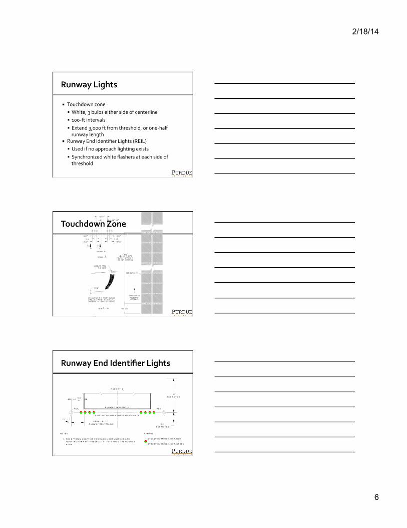
Touchdown zone White, 3 bulbs either side of centerline 100-‐ft intervals Extend 3,000 ft from threshold, or one-‐half runway length
Runway End Identifier Lights (REIL) Used if no approach lighting exists Synchronized white flashers at each side of threshold
9/29/2011 AC 150/5340-30F Appendix 1
151
F igure 34. Touchdown Zone L ighting Layout.
9/29/2011 AC 150/5340-30F Appendix 1
195
F igure 77. Typical Layout for R E I L .
4 0 '+ 3 5 '-0 '
R U N W A Y T H R E S H O L D
R U N W A Y CL
R E IL
E X IS T IN G R U N W A Y T H R E S H O L D L IG H T S
P A R A L L E L T O R U N W A Y C E N T E R L IN E
1 5 °
R E IL
1 0 0 'S E E N O T E 2
3 0 'S E E N O T E 2
S Y M B O L :
S T E A D Y B U R N IN G L IG H T , R E D
S T E A D Y B U R N IN G L IG H T , G R E E N
N O T E S
1 . T H E O P T IM U M L O C A T IO N F O R E A C H L IG H T U N IT IS IN L IN EW IT H T H E R U N W A Y T H R E S H O L D A T 4 0 F T F R O M T H E R U N W A YE D G E .
2 . A 1 0 0 F T U P W IN D A N D A 3 0 F T D O W N W IN D L O N G IT U D IN A LT O L E R A N C E IS P E R M IT T E D F R O M T H E R U N W A Y T H R E S H O L DIN L O C A T IN G T H E L IG H T U N IT S .
3 . T H E L IG H T U N IT S S H A L L B E E Q U A L L Y S P A C E D F R O M T H ER U N W A Y C E N T E R L IN E . W H E N A D J U S T M E N T S A R EN E C E S S A R Y T H E D IF F E R E N C E IN T H E D IS T A N C E O F T H EU N IT S F R O M T H E R U N W A Y C E N T E R L IN E S H A L L N O T E X C E E D1 0 F T .
4 . T H E B E A M C E N T E R L IN E (A IM IN G A N G L E ) O F E A C H L IG H TU N IT IS A IM E D 1 5 D E G R E E S O U T W A R D F R O M A L IN E P A R A L L E LT O T H E R U N W A Y C E N T E R L IN E A N D IN C L IN E D A T A N A N G L E 1 0D E G R E E S A B O V E T H E H O R IZ O N T A L . IF A N G L E A D J U S T M E N T SA R E N E C E S S A R Y , P R O V ID E A N O P T IC A L B A F F L E A N D C H A N G ET H E A N G L E S T O 1 0 D E G R E E S H O R IZ O N T A L A N D 2 0 D E G R E E SV E R T IC A L .
5 . L O C A T E T H E A D L E Q U IP M E N T A M IN IM U M D IS T A N C E O F 4 0F T F R O M O T H E R R U N W A Y S A N D T A X IW A Y S .
6 . IF R E IL S A R E U S E D W IT H V A S I, IN S T A L L R E IL S A T 7 5 F T F R O MT H E R U N W A Y E D G E . W H E N IN S T A L L E D W IT H O T H E R G L ID ES L O P E IN D IC A T O R S R E IL S S H A L L B E IN S T A L L E D A T 4 0 F T F R O MT H E R U N W A Y E D G E U N L E S S T H E R E A R E C O N C E R N S W IT H J E T
7 . T H E E L E V A T IO N O F B O T H U N IT S S H A L L B E W IT H IN 3 F T O FT H E H O R IZ O N T A L P L A N E T H R O U G H T H E R U N W A YC E N T E R L IN E .
B L A S T A N D W IN G V O R T IC E S . S E E F A A O R D E R J O 6 8 5 0 .2 B F O RA D D IT IO N A L IN F O R M A T IO N .
2/18/14
7
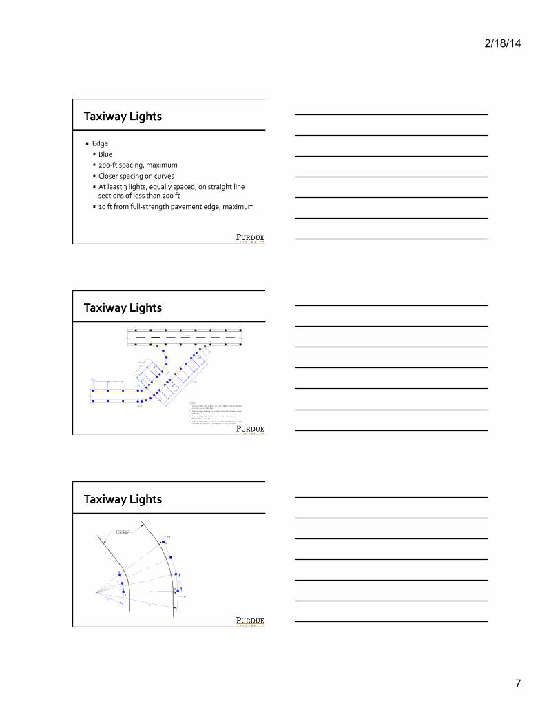
Edge Blue 200-‐ft spacing, maximum Closer spacing on curves At least 3 lights, equally spaced, on straight line sections of less than 200 ft
10 ft from full-‐strength pavement edge, maximum
9/29/2011 A
C 150/5340-30F
Appendix 1
137
Figure 20.
Typical Edge Lighting Configuration.
T a x iw a y e d g e lig h t s p a c in g o n lo n g s tra ig h t ta x iw a y s e c tio n s m u s t n o t e x c e e d 2 0 0 fe e t.
T a x iw a y e d g e lig h t s p a c in g o n s h o r t s e c tio n s is s h o w n o n f ig u re s 1 0 , 1 1 , a n d 1 6 .
T a x iw a y L ig h t s p a c in g o n c u rv e d s e c tio n s m u s t b e a s s h o w n o n f ig u re 1 7 .
1 .
3 .
2 .
N O T E S
T a x iw a y e d g e lig h ts a re b lu e . R u n w a y e d g e lig h ts a re w h ite o r y e llo w a s s p e c if ie d in p a ra g ra p h 2 .1 .2 (a ) o f th is A C .
4 .
AC
150/5340-30F 9/29/2011
Appendix 1
134
Figure 17.
Spacing of Lights on Curved Taxiw
ay Edges.
N O T E S :
1 . F o r ra d ii n o t l is te d , d e te rm in e "Z " s p a c in g b y lin e a r in te rp o la t io n .
2 . "Z " is th e a rc le n g th .
S ID E S O FT A X IW A Y
P T
P T
U n ifo rm ily s p a c e lig h ts o n c u rv e d e d g e s . D o n o t e x c e e d th e v a lu e s d e te rm in e d fro m th e a b o v e ta b le .
3 .
4 . O n c u rv e d e d g e s in e x c e s s o f 3 0 d e g re e s a rc , d o n o t in s ta ll le s s th a n th re e lig h ts in c lu d in g th o s e a t th e p o in ts o f ta n g e n c y (P T ).
B
B
B
B
2/18/14
8
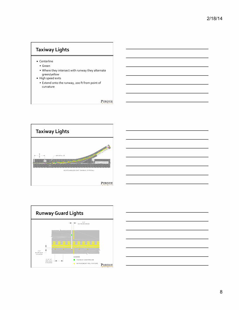
Centerline Green Where they intersect with runway they alternate green/yellow
High speed exits Extend onto the runway, 200 ft from point of curvature
AC
150/5340-30F 9/29/2011
Appendix 1
162
Figure 45.
Taxiway C
enterline Lighting Configuration for A
cute-Angled Exits.
N O T E S :
A C U T E -A N G L E D E X IT T A X IW A Y (T Y P IC A L )
P C
P T
D IM E N S IO N S A R E E X P R E S S E D A S F E E T [M E T E R S ].
T H E T A X IW A Y C E N T E R L IN E "L E A D O F F " L IG H T S S H O U L DB E IN S T A L L E D O N T H E R U N W A Y E X IT S ID E O F T H E T A X IW A Y C E N T E R L IN E M A R K IN G A T 5 0 [1 5 ] S P A C IN G .
T H E T A X IW A Y C E N T E R L IN E "L E A D O F F " L IG H T S A R E IN S T A L L E D IN R E L A T IO N T O T H E C U R V E D E S IG N A T E D A ST H E T R U E C E N T E R L IN E O F T H E T A X IW A Y P A T H .
T H E O R IE N T A T IO N O F T H E L IG H T B E A M S S H A L L B E A SS P E C IF IE D IN P A R A G R A P H 4 .3 . i.
1 .
2 .
3 .
4 .
T A X IW A Y C M A R K IN G
R U N W A Y C M A R K IN G
L
L
T A X IW A Y C L IG H T
R U N W A Y C L IG H T
L
L2 .5 [ .0 8 ]
3 [0 .9 ]
2 .5 [ .0 8 ]
D E T A IL A
T A X IWA Y C
MA R K IN G
R U N W A Y C M A R K IN G
L
L
20
0 [6
0]
S E E D E T A IL A
3 0 °
AC 150/5340-30F 9/29/2011 Appendix 1
166
F igure 49. In-Pavement Runway Guard L ight Configuration.
L E G E N D
T A X IW A Y C E N T E R L IN E
IN -P A V E M E N T R G L F IX T U R E
9 '-1 0 " ± 2 "[3 M ± 5 c m ]5 P L A C E S
2 '-2 "[0 .6 1 M ± 5 c m
5 P L A C E S
2 '-0 "[0 .6 1 M ] M A X IM U M
AC 150/5340-30F 9/29/2011 Appendix 1
166
F igure 49. In-Pavement Runway Guard L ight Configuration.
L E G E N D
T A X IW A Y C E N T E R L IN E
IN -P A V E M E N T R G L F IX T U R E
9 '-1 0 " ± 2 "[3 M ± 5 c m ]5 P L A C E S
2 '-2 "[0 .6 1 M ± 5 c m
5 P L A C E S
2 '-0 "[0 .6 1 M ] M A X IM U M
2/18/14
9
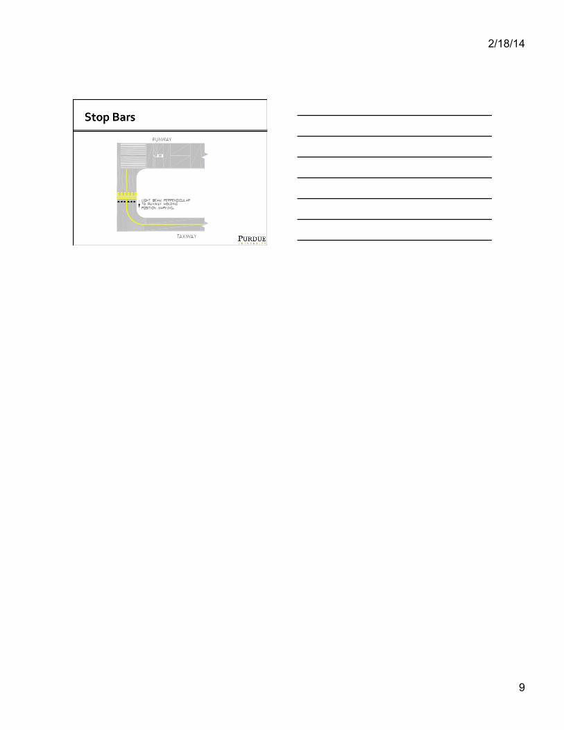
AC
150/5340-30F 9/29/2011
Appendix 1
168
Fig
ure
51.
Ty
pic
al L
igh
t Beam
Orie
nta
tion
for In
-Pa
vem
en
t RG
Ls an
d S
top
Ba
rs.