499 9 electrical - boater's pocket reference boater’s pocket reference: chapter 9 use nylon...
TRANSCRIPT

9 ElEctricalintroductionThis chapter attempts to give the reader a basic understand-ing of marine electrical systems and to give an appreciation of how they differ from electrical systems in a house or automobile. Wiring a house doesn’t qualify a person for wir-ing a boat, and I hope to help the reader see and appreciate that fact.Understanding a boat’s electrical systems should:
Assist in solving basic electrical problems underway.Help you communicate better with your electrician and know what standards to expect from him or her.Help in evaluating the quality of the electrical installation on a boat you are thinking of buying.Make you more aware of potentially dangerous or unsafe conditions.
What this chapter does not do is qualify anyone to carry out marine electrical work.The U.S. Code of Federal Regulations (CFR) contains regu-lations pertaining to electrical systems on gasoline powered boats in Title 33 CFR Sections 183.401-183.460. The first section states,“This subpart applies to all boats that have gasoline engines, except outboard engines, for electrical generation, mechanical power, or propulsion,” and although this statement limits the legal applicability, it would be a good idea to think of these regulations as setting a minimum standard for any boat with electrical systems onboard.These actual regulations can be found at www.gpoaccess.gov/cfr/index.html. The U.S. Coast Guard has also produced an 86-page Adobe Acrobat .pdf document that provides a good explanation of these regulations. It can can be down-loaded at no cost from http://www.uscgboating.org/safety/boatbuilder/electrical/electrical.htm. Much of the material in this section is derived from these documents. If you are actually planning on some do-it-yourself boat wiring, it should conform to the standards established by the American Boat and Yacht Council (ABYC). This is an organization of boat builders and various other marine related individuals and firms that sets standards that are generally accepted as requirements for building recreational boats. They offer for purchase part or all of their standards and several books, including the three mentioned below. You
••
•
•
499
Electrical 503
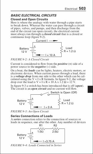
BasIc ElEctrIcal cIrcuItsclosed and open circuitsHere is where the analogy with water through a pipe starts to break down. Whereas the water can pass through a circuit of pipes, valves, and pumps, and then discharge from the end of the circuit (an open circuit), the electrical current must always run through a closed circuit that is a closed or continuous loop (figure 9-2).
Current is considered to flow from the positive (+) side of a power source to the negative (–) side. On a boat, the loads can be lights, heaters, electric motors, or electronic devices. When current passes through a load, there is a voltage drop from one side to the other which can be cal-culated using the V = I x R formula. In figure 9-2, the voltage drop over the load is V = I x R = 10 A x 1.2 Ω = 12 V. In figure 9-3 a switch has been introduced that is off (open). The circuit is an open circuit and no current will flow.
series connections of loadsA series connection refers to the connection of sources or loads in sequence, one after the other. Any number of devices
+
−
Current I
Battery12 V
LoadR = 1.2 Ω
I = 10 A
FIGURE 9-2: A Closed Circuit
Battery12 V
LoadR = 1.2 Ω
I = 0 A−
+
Switch is Open (Off)
FIGURE 9-3: An Open Circuit
Battery12 V −
+ 1.0Ω 2.0Ω
R1 R2
I =3.75 AFIGURE 9-4: Loads Connected in Series

508 Boater’s Pocket Reference: Chapter 9
Kilowatts (kW) is the electrical (and metric) equivalent of horsepower and 1 kilowatt is equal to 1000 watts.To convert from kilowatts to horsepower multiply by 1.341. To convert from horsepower to watts multiply by 0.7457 (0.75 is a good approximation and is easier to remember). Example: To power a generator that produces 10 kW requires a 10 kW x 1.341 hp/kW = 13.4 hp diesel engine, assuming no losses.
ElEctrIcal dIagram symBols
ElEctromagnEtIsm and BasIc ElEctrIcal dEvIcEsElectromagnetic Force
Diode Capacitor
CurrentFlow
−+
Induced Magnetic Field(Arrows Point North)
FIGURE 9-10: Magnetic Field Around a Current Carrying Wire
FIGURE 9-9: Commonly Used Electrical Symbols

516 Boater’s Pocket Reference: Chapter 9
Use nylon insulated rather than PVC-insulated connectors, since nylon withstands crimping better, or use connectors with heat-shrink sealed insulation.Double crimp connectors are available from companies, such as Ancor, that have a second crimp that crimps onto the in-sulation to give a better grip. Good ratcheting crimping tools cost anywhere from $50 to $140, but they are well worth it if you are doing more than a couple of connections. Test crimps by trying to pull the wire out of the connector.Solder should not be used as the sole means of connecting cable, because constant flexing can cause the soldered con-nection to break; however, there are differences of opinion as to whether solder should be used on crimped connectors. The argument for using solder is that it seals the end of the wire against moisture. The argument against is that if too much solder is applied it will flow up the wire and solidify it, thus making it susceptible to failure from flexing. A better alter-native to soldering is probably to use the heat-shrink sealed connectors although they cost almost three times as much.
FlatSpade
NO
FlangedSpade
Terminal(Okay)
FrictionTerminal orConnector
(Okay)
ButtConnector
(Okay)
RingTerminal
(Best)
Heat Shrink SealedRing Connector
(Best)
Wire NutNO
FIGURE 9-16: Cable Terminals and Connectors

Electrical 519
number in SAE having a slightly smaller diameter than wire of the same gauge number in AWG. In the United States, the regulations state that AWG gauge wire must be used for 50 volt and above systems, and either AWG or SAE may be used below 50 volts.The gauge system was devised so that a decrease of three gauge numbers (e.g., 15 to 12) results in an approximate doubling of cross-sectional area, which corresponds to a doubling of current carrying capacity. It’s also handy to know that a decrease of two gauge numbers will result in approximately 1.6 times or 60 percent more current carrying capacity. So going from 14 to 12 gauge will add 60 percent to
allowable current. Figure 9-17 shows some typical wire sizes taken from table 9-1 on the next page and current carrying capacity (ampacity) at 60 degrees Celsius taken from table 9-2 on page 522.
The Circular MilThe cross-sectional area of wire is usually specified as cir-cular mils rather than square inches or millimeters. A mil is
1/1000 of 1 inch or 0.001 inches. A circular mil (CM) is the area of a circle that has a diameter of 1 mil (0.001 in). With some manipulation we arrive at equation 9-6 for calculating circular mils from diameter:In equation 9-6 use 1550 instead of 1,000,000 if you have the diameter in millimeters.The use of the circular mil for measuring cross-sectional area eliminates the need to use pi or divide the diameter by 2 to get radius when doing area calculations.
2 Gauge 00 Gauge8 Gauge14 Gauge18 Gauge
10 Amps225 Amps140 Amps
55 Amps20 Amps
FIGURE 9-17: Actual Wire Sizes (Scaled to Actual Size)
CM = D2 × 106 = D2 × 1,000,000Where: CM = Circular Mils
D = Diameter in inches
EQUATION 9-6: Calculation of Circular Mils

520 Boater’s Pocket Reference: Chapter 9
Standard Wire SizesTable 9-1 lists standard wire sizes along with their cross-sec-tional areas and resistance per unit length.
Current Carrying Capacity Limited by Wire HeatingThe first step in selecting a conductor size is to determine the continuous or steady state current that it will carry without overheating. Note that surges higher than continu-ous for short periods of time are allowed. The most common example of current surge occurs during the starting of an electric motor.The top half of table 9-2 on page 522 contains the allowable amperages for no more than two conductors bundled, as specified in U.S. 33 CFR 183.425. Note: The top half of table 9-2 and the factors for use in engine spaces and correction factors for the number of current carrying conductors are the same as in tables in U.S. 33 CFR 183.425, in ABYC stan-dards and in Transport Canada Standards for Small Vessels.To use the table first enter the table in the column with the conductor insulation temperature rating of the cable you propose to use. This rating should be printed on the cable. Then proceed down the column until an amperage is reached that is greater than or equal to the desired continuous current and read the wire gauge from the left-hand column. This is the minimum diameter wire that may be used to carry that amperage.
Wirediameter X-section area
(circular Mils)resistance @ 20° c (aWG)
aWG aWG saE Ω/ 1000 ft
Ω/ kmGauge in mm cM cM
18 0.0403 1.024 1620 1537 6.3850 20.942816 0.0508 1.290 2580 2336 4.0160 13.172514 0.0641 1.628 4110 3702 2.5250 8.282012 0.0808 2.052 6530 5833 1.5880 5.208610 0.1019 2.588 10380 9343 0.9989 3.27648 0.1285 3.264 16510 14810 0.6282 2.06056 0.1620 4.115 26240 24538 0.3951 1.29594 0.2043 5.189 41740 37360 0.2485 0.81512 0.2576 6.543 66360 62450 0.1563 0.51271 0.2893 7.348 83690 77790 0.1239 0.40640 0.3249 8.252 105600 98980 0.0983 0.3224
00 0.3648 9.266 133100 125100 0.0779 0.2555000 0.4096 10.404 167800 158600 0.0618 0.2027
0000 0.4600 11.684 211600 205500 0.0490 0.1607
TABLE 9-1: Standard Wire Sizes and Specifications

Electrical 527
Effect of Voltage Drop on Conductor SizingHaving determined a conductor size adequate to carry the specified current, we must also determine the size of conductor to keep voltage drop over its length to less than a specified amount (usually 3 percent or 10 percent). The final conductor size is the larger (smallest gauge number) of the two determinations.Many electrical devices will work fine with a 10 percent voltage drop but others, particularly some electric motors and some electronic equipment, will suffer. It is preferable to wire for a 3 percent maximum drop wherever possible, and only use the 10 percent maximum drop where absolutely necessary in situations with very high current draw, such as operating bow thrusters or a windlass (assuming they have motors that can tolerate the lower voltage).Equation 9-7 relates voltage drop to length and cross-sec-tional area of a conductor.
With equation 9-7(2) we can determine the area in circular mils (CM) that corresponds to a given length (L) of conduc-tor and current (I). The constant K varies with temperature and for boat calculations K = 10.75 is the standard used by the ABYC and Transport Canada).Example:Assume we have an appliance that draws 30 amps at 12 volts. The distance from the source to the appliance is 12 feet. We want to limit the voltage drop to 3 percent.Total conductor length out to appliance and back L = 12 x 2 = 24 feet. Allowed voltage drop = 3% x 12 V = 0.36 V
V = I × (K × L
A) (1) A =
K × L × IV
(2)or rearranged
Where: V = Voltage drop across the length of conductor (volts)I = Current flow (amperes)L = Length of conductor (feet or meters)A = Cross sectional area of conductor (circular mils)K = Constant relating resistance to length and area of conductor = 10.75 for L in feet = 35.26 for L in meters
EQUATION 9-7: Conductor Area for Voltage Drop and Length
530 Boater’s Pocket Reference: Chapter 9
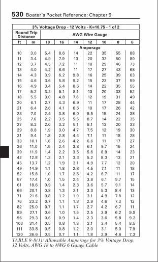
3% Voltage drop - 12 Volts - K=10.75 - 1 of 2round trip distance aWG Wire Gauge
ft m 18 16 14 12 10 8 6amperage
10 3.0 5.4 8.6 14 22 35 55 8811 3.4 4.9 7.9 13 20 32 50 8012 3.7 4.5 7.2 11 18 29 46 7313 4.0 4.2 6.6 11 17 27 43 6814 4.3 3.9 6.2 9.8 16 25 39 6315 4.6 3.6 5.8 9.2 15 23 37 5916 4.9 3.4 5.4 8.6 14 22 35 5517 5.2 3.2 5.1 8.1 13 20 33 5218 5.5 3.0 4.8 7.6 12 19 31 4920 6.1 2.7 4.3 6.9 11 17 28 4421 6.4 2.6 4.1 6.6 10 17 26 4223 7.0 2.4 3.8 6.0 9.5 15 24 3825 7.6 2.2 3.5 5.5 8.7 14 22 3527 8.2 2.0 3.2 5.1 8.1 13 20 3329 8.8 1.9 3.0 4.7 7.5 12 19 3031 9.4 1.8 2.8 4.4 7.1 11 18 2833 10.1 1.6 2.6 4.2 6.6 11 17 2736 11.0 1.5 2.4 3.8 6.1 9.7 15 2439 11.9 1.4 2.2 3.5 5.6 8.9 14 2342 12.8 1.3 2.1 3.3 5.2 8.3 13 2145 13.7 1.2 1.9 3.1 4.9 7.7 12 2049 14.9 1.1 1.8 2.8 4.5 7.1 11 1852 15.8 1.0 1.7 2.6 4.2 6.7 11 1757 17.4 1.0 1.5 2.4 3.8 6.1 9.7 1561 18.6 0.9 1.4 2.3 3.6 5.7 9.1 1466 20.1 0.8 1.3 2.1 3.3 5.3 8.4 1371 21.6 0.8 1.2 1.9 3.1 4.9 7.8 1276 23.2 0.7 1.1 1.8 2.9 4.6 7.3 1282 25.0 0.7 1.1 1.7 2.7 4.2 6.7 1189 27.1 0.6 1.0 1.5 2.5 3.9 6.2 9.996 29.3 0.6 0.9 1.4 2.3 3.6 5.8 9.2103 31.4 0.5 0.8 1.3 2.1 3.4 5.4 8.5111 33.8 0.5 0.8 1.2 2.0 3.1 5.0 7.9120 36.6 0.5 0.7 1.1 1.8 2.9 4.6 7.3
TABLE 9-8(1): Allowable Amperage for 3% Voltage Drop, 12 Volts, AWG 18 to AWG 6 Gauge Cable

540 Boater’s Pocket Reference: Chapter 9
Comparing Battery CostsBatteries of each type were randomly selected from various vendors and the prices averaged for each type in table 9-11. Note that prices differed widely for various vendors and brands so just consider these as a rough comparison.
Because of charging considerations (which we’ll discuss further on) AGM, gel-cell and wet-cell batteries can’t be mixed together. Once the decision on battery type is made, that should be the only type of battery on the boat, including the starting battery.
Matching Batteries to the Application (Starting or Deep-Cycle)Usually on a small boat like a runabout, only a starting bat-tery is installed, and its only function is to start the engine, although it may run some very low power devices such as a bilge pump or radio from time to time. Obviously, a starting type battery makes the most sense, since a deep-cycle battery with enough cold cranking amps to start the engine would be excessively large and expensive. A quick look at table 9-11 shows how you get a lot more CCAs per dollar with a starting battery.Many smaller boats are outfitted for fishing with an electric trolling motor that requires battery power while the main en-gine is stopped. Obviously you don’t want to be discharging the starter battery to run that trolling motor or you may end up rowing those fish back to shore. The solution is to provide a second battery for powering the trolling motor, which allows the starting battery to be used exclusively for engine starting. The second battery should be a deep-cycle battery, which is suited to being deeply discharged as is likely in this situation. In addition to deep-cycle and starting batteries, there are dual-purpose batteries designed to perform both functions. If a second battery is to be used as a back up starting battery, this could provide an argument for it being a dual-purpose
type usage Volts $ / ah cca / $
AGM Deep-cycle 12 2.00 3.27Gel Deep-cycle 12 2.25 2.54Wet-cell Deep-cycle 12 1.18 4.23Wet-cell Deep-cycle—golf cart 6 0.83 3.96Wet-cell Starting 12 n/a 12.12
TABLE 9-11: Comparative Cost of Battery Types
Electrical 547
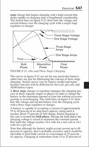
stage charge that begins charging with a high current that drops rapidly so charging time is lengthened considerably. The dotted lines on figure 9-21 show how the voltage and current behave over the charging cycle with a single stage regulator or charger.
The curves in figure 9-21 are not for any particular battery; rather they are just for illustrating the concept of three stage charging. Actual curves vary by battery model and manu-facturer and also will be different for wet-cell, gel-cell, and AGM battery types.A three stage charger or regulator manages the charging pro-cess in three separate stages or phases in order to charge the battery in the minimum amount of time but without excessive gassing or overcharging. The solid lines on figure 9-21 show how the voltage and current behave over the charging cycle with a three stage regulator or charger.A battery is capable of accepting a current of approximately 25 to 40 percent of its amp-hour capacity rating until it reaches about 75 percent of full charge. Initial charging at this rate is termed the bulk phase. During the bulk phase the charging voltage is raised to maintain the constant current flow until the voltage reaches 14.4 volts for a wet-cell or 14.1 volts for a gel-cell. Note that although the battery might accept current up to 40 percent of capacity, that is probably excessive and it would be advisable to limit bulk current to a maximum of 25 percent of capacity. Charging at somewhere from 15 to 25 percent of
Three Stage VoltageOne Stage Voltage
One Stage Amps
Three StageAmps
BulkPhase
AbsorptionPhase
FloatPhase
Time
FIGURE 9-21: One and Three Stage Charging

Electrical 553
shorepowerShorepower ReceptaclesToday most marinas provide some kind of shorepower although the voltage and current vary. Typical hookups are: 120 volt/20 amps, 120 volt/30 amps, 120 volt/50 amps and 240 volt/50 amps. The standard locking receptacles used for dock outlets are shown in figure 9-23 along with the conduc-tor color pinouts used to maintain correct polarity.
Note how the 250 V receptacle shows B/R and R/B on two of the prongs. This just means that the B/R prong can be con-nected to either black or red and the R/B prong must be con-nected to the other color (i.e., if the B/R prong is connected to red then the R/B prong must be connected to black).Knowing the pinout, it’s easy to check for correct polarity before plugging in. With 125 V receptacles:
W to G should read 0 V. If W to G is around 120 V then polarity has been reversed. If W to G is greater than 0 V
•
20 A 125 V Locking 30 A 125 V Locking
50 A 125 V Locking 50 A 250 V Locking
G
WB
W
W W
B
B
G
G
G
B/R
R/B
FIGURE 9-23: Shorepower Receptacle Pinouts

Electrical 555
Things to note about this hookup:Neutral is connected to ground only at the source, in this case the marina.Polarity is maintained throughout.A 3 pole breaker that breaks all three current carrying conductors is required near the shorepower inlet.The galvanic isolator prevents stray currents from flowing through the ground wire.There are no breakers or switches in the ground conductors.The AC ground (green) is grounded inside the boat.
•
••
•
•
•
Neutral (White)
Hot 120 V (Black)
Hot 120 V (Red)
Ground (Green)
Marina
Shorepower Cable
ShoreConnection
BoatConnection
120 V 240 V
120 V
3 pole breaker
BoatGround
GalvanicIsolator
R
W
B
Ground
Shorepower Switch
Polarity Indicator
FIGURE 9-24: Shorepower Circuit 240 V

Electrical 559
work with the sine wave form of AC and that some devices just don’t work well with square wave current. Marine inverters are available that produce either true sine wave (TSW) or modified sine wave (MSW) output. The modified sine wave attempts to approximate the sine wave through a series of steps as shown in figure 9-27. The modified sine wave is better than the square wave, but not as desirable as a true sine wave. Electronics such as television sets and stereo systems tend to be quite sensitive to the wave-form and will work best with TSW. Microwave ovens may not work very efficiently with MSW but they should work. Heat-producing appliances, such as light bulbs, toasters, and electric frying pans, don’t care about the wave form at all. As you might expect, a TSW inverter costs more than a MSW inverter. Browsing through a marine equipment catalog, I found 2000-watt TSW inverter/chargers priced around $1600 to $1800 and a 2000-watt MSW inverter/charger at about $1300.
Inverter SizeInverters are sized by watts, so wattages for all the 120-volt loads on the inverter need to be tabulated. Keep in mind that some of the loads will be continuous and some higher loads will be for relatively short periods. For example, starting an electric motor usually requires a power surge more than double the running wattage. Other examples of short period loads include a microwave oven or a hair dryer. It is impor-tant to distinguish between the two because inverters have both a continuous and peak rating.Inverters are available up to 2000 or even 3000 watts (5000 W or 8000 W surge) capacity. Figure 3000 watts is about equivalent to 110 V shorepower of 3000 W/ 110 V ≅ 30 amps. Without even allowing for efficiency losses this will translate to more than a 300 amp draw on the house batter-ies! Just running a 1000 watt microwave for five minutes
170 V
170 V
0 V
Sine Wave
Modified Sine Wave
FIGURE 9-27: Sine Wave and Modified Sine Wave AC
Electrical 565
or less noble. Since the least noble metal is the one with the most negative voltage potential, it is the least noble metal that will corrode when the two metals are joined in an electrolyte. The less noble metals are more active and more susceptible to corrosion.To get an idea of the potentials involved, the difference in voltage potential from platinum at the top of the list to zinc near the bottom of the list is approximately –1.8 volts. That is to say, zinc is negative 1.8 volts relative to platinum and cur-rent flow through the connection will be from the platinum (+) to the zinc (–). Another example would be zinc at 1.3 V less than copper.In general, metals far apart on the series can be expected to produce more galvanic corrosion and metals close together very little galvanic corrosion.
Galvanic corrosion on BoatsFor example, if an aluminum propeller is mounted on a stain-less steel shaft and immersed in seawater, the aluminum prop will experience galvanic corrosion since aluminum is further down the table than stainless steel. This of course, is not good; we need to find a way to stop the galvanic corrosion of the propeller. It turns out that if three, rather than two, metals are linked together in our galvanic cell, only the least noble of the three metals experiences galvanic corrosion and the two more noble metals don’t corrode and are protected (at least until the less noble metal has completely corroded away). This applies to any number of metals connected together; only the least noble metal will experience galvanic corrosion.This explains the zincs we see mounted on propeller shafts, rudders, hulls, etc. They are near the bottom of the galvanic series and being lower down than the steels, bronzes, and aluminums, serve to protect by sacrificing themselves, thus the term sacrificial zincs or anodes. Zincs must be inspected and replaced periodically, since they corrode, and they must never be painted if they are to function as intended.Something to note: Galvanic corrosion occurs without the presence of electricity from any external source; it is entirely self-generated by the action between dissimilar metals con-nected together in an electrolyte. It can be experienced just as easily on a sail boat with no installed electrical systems, as on a fully electrified powerboat.

572 Boater’s Pocket Reference: Chapter 9
some measure of protection is provided to personnel who don’t have sense enough to get below when there’s lightning around. There are several guidelines published as to minimum turn-ing radius of the main down conductor, minimum size of copper strands, acceptable connections, proximity to other equipment, methods of isolating electronic equipment, etc. The three books mentioned at the beginning of this chapter, the ABYC, and Dr. Thomson’s website all provide detailed installation related information and requirements.
is lightning Protection a Good idea?As we’ve seen, a lightning protection does not prevent light-ning strikes; rather it provides a relatively safe path through your boat for the strike to reach ground. There are those who say that installation of a lightning protection system increases the chances of being struck by lightning. Virtually all the experts dispute this, stating there is no reason for this to be so and no statistical evidence to the support this view.In the very first sentence on his website, Dr. Thomson states, “The only benefit of not protecting a yacht from lightning is saving the cost of the protection system.”I hope this discussion will persuade you to analyze further the whole issue of lightning protection on your boat, par-ticularly if you do your boating on the East Coast or Florida (where most lightning strikes occur).
cHEcKlistBasic ElEctrical toolKit
Spare fuses (if your boat uses them) Screwdrivers -slotted Screwdrivers -phillips Needlenose pliers Linemans pliers Wire stripper Crimping tool Selection of marine grade crimping terminals Electrical tape Heat shrink tubing Multimeter Spare wire in various sizes (marine grade) Battery testing hydrometer 110 V receptacle polarity tester Battery terminal puller Soldering iron and rosin core solder