4/8ch dvr - id vie dvr iv-411eco / iv-81s1eco01(v0.2) user manual this document contains preliminary...
TRANSCRIPT

1
4/8CH DVR
User ManualIV-411ECO / IV-811ECO S01(v0.2)
This document contains preliminary information and subject to change without notice.

2
This symbol is intended toalert the user to the presenceof unprotected “Dangerousvoltage" within the product'senclosure that may be strongenough to cause a risk ofelectric shock.
This symbol is intended toalert the user to the presenceof important operating andmaintenance (servicing)instructions in the literatureaccompanying the appliance.
WARNINGTO REDUCE THE RISK OF FIRE ORELECTRIC SHOCK, DO NOT EXPOSETHIS APPLIANCE TO RAIN ORMOISTURE.
NOTE: This equipment has been testedand found to comply with the limits for aclass digital device, pursuant to part 15 ofthe FCC Rules. These limits are designedto provide reasonable protection againstharmful interference when the equipment isoperated in a commercial environment.This equipment generates, uses, and canradiate radio frequency energy and, if notinstalled and used in accordance with theinstruction manual, may cause harmfulinterference to radio communications.Operation of this equipment in a residentialarea is likely to cause harmful interferencein which case the user will be required tocorrect the interference at his own expense.
Disposal of Old Electrical & Electronic Equipment (Applicable in the EuropeanUnion and other European countries with separate collection systems)
This symbol on the product or on its packaging indicates that this product shall not be treatedas household waste. Instead it shall be handed over to the applicable collection point for therecycling of electrical and electronic equipment. By ensuring this product is disposed ofcorrectly, you will help prevent potential negative consequences for the environment andhuman health, which could otherwise be caused by inappropriate waste handling of thisproduct. The recycling of materials will help to conserve natural resources. For more detailedinformation about recycling of this product, please contact your local city office, your householdwaste disposal service or the shop where you purchased the product.

2009.10.27 S01 V0.23
Table of Contents
CHAPTER 1 PACKING DETAIL AND INSTALLATION _____________________ 51-1 PACKING__________________________________________________ 51-2 Hard Disk Installation _______________________________________ 6
CHAPTER 2 PANEL LOCATION _______________________________________ 72-1 FRONT PANEL CONTROLS __________________________________ 72-2 8CH REAR PANEL CONNECTORS ____________________________ 82-3 4CH REAR PANEL CONNECTORS ____________________________ 9
CHAPTER 3 LIVE, PLAYBACK AND PTZ OPERATIONS _________________ 103-1 LIVE Mode _______________________________________________ 103-2 PLAYBACK Mode _________________________________________ 133-3 PTZ Mode ________________________________________________ 15
CHAPTER 4 MAIN MENU SETUP ___________________________________ 174-1 RECORD SETUP __________________________________________ 18
4-1.1 Quality & Frame Rate Setup ___________________________ 194-2 EVENT SETUP ____________________________________________ 19
4-2.1 MOTION SETUP ______________________________________ 204-2.1.1 MOTION AREA SETUP____________________________ 21
4-2.2 SENSOR SETUP ______________________________________ 214-3 SCHEDULE SETUP ________________________________________ 22
4-3.1 Schedule Record Setup _______________________________ 234-3.2 Holiday Setup ________________________________________ 23
4-4 CAMERA SETUP __________________________________________ 244-5 ACCOUNT SETUP _________________________________________ 25
4-5.1 Permission Setup _____________________________________ 264-5.2 User Picture Setup ___________________________________ 26
4-6 NETWORKING SETUP______________________________________ 274-6.1 NETWORKING SETUP _________________________________ 27
4-6.1.1 DHCP __________________________________________ 274-6.1.2 LAN____________________________________________ 284-6.1.3 ADSL _________________________________________ 28
4-6.2 HTTP Setup _________________________________________ 294-6.3 DDNS Setup ________________________________________ 294-6.4 Mail Setup __________________________________________ 30
4-7 PTZ & RS485 SETUP ______________________________________ 314-8 SYSTEM SETUP ___________________________________________ 32
4-8.1 DISPLAY SETUP ______________________________________ 334-8.2 DATE/TIME SETUP ____________________________________ 34
4-8.2.1 CHANGE DATE & TIME ___________________________ 344-8.2.2 TIME ZONE AND DAYLIGHT SAVING TIME SETUP ___ 354-8.2.3 INTERNET TIME SETUP __________________________ 35
4-8.3 BUZZER & RELAY SETUP _____________________________ 364-8.4 SPOT SETUP ________________________________________ 37
4-9 UTILITY SETUP ___________________________________________ 384-10 DIAGNOSTIC ____________________________________________ 39
CHAPTER 5 BACKUP & SEARCH ___________________________________ 405-1 BACKUP SETUP __________________________________________ 405-2 SEARCH SETUP __________________________________________ 41
5-2.1 EVENT SEARCH ______________________________________ 415-2.1.1 CRITERIA SETUP FOR EVENT SEARCH_____________ 42

2009.10.27 S01 V0.2 4
5-2.2 TIME SEARCH _______________________________________ 435-3 AP Software Installation and Setup __________________________ 445-4 How to do remote monitoring through IE ____________________ 465-4 AP Software Operation _____________________________________ 48
CHAPTER 6 SPECIFICAITONS _____________________________________ 49CHAPTER 7 MOBILE APPLICATION INSTALLATION AND USAGE _________ 51
7-1 Mobile Application Installation and Operation for Symbian System517-1.1 Mobile Application Installation __________________________ 517-1.2 Mobile Application Operation ___________________________ 52
7-1.2.1 Add New Login DVR _____________________________ 527-1.2.2 Logging Onto the DVR ___________________________ 527-1.2.3 Modify the Login Information of DVR _______________ 537-1.2.4 Delete the Login Information of DVR _______________ 53
7-1.3 Live Monitoring Operation _____________________________ 537-1.3.1 Scroll the Image _________________________________ 547-1.3.2 Image Quality Setup _____________________________ 547-1.3.3 Channel Display _________________________________ 547-1.3.4 Size of Image ___________________________________ 557-1.3.5 Rotate the image ________________________________ 557-1.3.6 Alarm __________________________________________ 55
7-2 Mobile Application Installation and Operation for Windows Mobile System _______________________________________________________ 56
7-2.1 Mobile Application Installation __________________________ 567-2.2 Mobile Application Operation ___________________________ 577-2.3 Operation under the LIVE monitoring. ___________________ 57
7-2.3.1 Operation uner the LIVE monitoring for Jrviewer ____ 587-2.3.2 Operation under the LIVE monitoring for H264 Pocket 59
CHAPTER 8 CMS INSTALLATION AND USAGE GUIDE __________________ 608-1 CMS Installation __________________________________________ 608-2 CMS LOGIN AND ENVIRONMENT ____________________________ 638-3 DVRs, Groups & Events ___________________________________ 64
8-3.1 View DVR Group List ________________________________ 648-3.2 View Event Logs _____________________________________ 65
8-4 Local PC Information and Control ___________________________ 658-5 Main Display _____________________________________________ 66
8-5.1 Audio Control ________________________________________ 668-5.2 eMAP Display ________________________________________ 678-5.3 PTZ Control _________________________________________ 68
8-6 Operation Bar ____________________________________________ 698-6.1 User administration ___________________________________ 708-6.2 DVR Administration ___________________________________ 708-6.3 Group Administration _________________________________ 718-6.4 eMap Administration __________________________________ 728-6.5 Remote Play _________________________________________ 738-6.6 HDD Playback________________________________________ 748-6.7 File Playback ________________________________________ 748-6.8 Event Playback_______________________________________ 758-6.9 Snapshot Data _______________________________________ 758-6.10 Recording Data _____________________________________ 76
APPENDIX I I-DVR.NET REGISTRATION ____________________________ 77APPENDIX II Remote Monitoring IE ActiveX Control Installation Instruction ___ 79

2009.10.27 S01 V0.25
CHAPTER 1 PACKING DETAIL AND INSTALLATION1-1 PACKING
1. DVR
2. Quick Start 3. IR Remote Control 4.Batteries x2Please press “DVR1”button before operation
5. CD 6. Hard Disk Mount x2 7.Screws x20
8. Power Adaptor 9. Power Cord 10. SATA Cord x 1
Note: Standard shipping products do not include HDD

2009.10.27 S01 V0.2 6
1-2 Hard Disk Installation
Step 1) Fix the HDD to rack mount with the screws as indicated.
Step 2) Place the HDD on the HDD plate and screw it as indicated.
Step 3) Connect the power and the SATA cables as indicated.
Note: After installation, please initialize Hard Disk before starting to record. For more detailedinformation, please check out User Manual 4-9 System Tools for reference.
2009.10.27 S01 V0.27
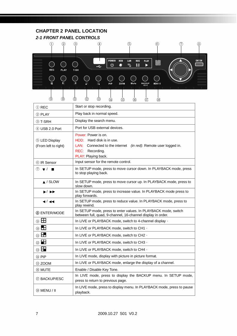
CHAPTER 2 PANEL LOCATION2-1 FRONT PANEL CONTROLS
REC Start or stop recording.
PLAY Play back in normal speed.
T-SRH Display the search menu.
USB 2.0 Port Port for USB external devices.
LED Display(From left to right)
Power: Power is on.HDD: Hard disk is in use.LAN: Connected to the internet (in red): Remote user logged in.REC: Recording.PLAY: Playing back.
IR Sensor Input sensor for the remote control.
/ In SETUP mode, press to move cursor down. In PLAYBACK mode, pressto stop playing back.
/ SLOW In SETUP mode, press to move cursor up. In PLAYBACK mode, press toslow down.
/ In SETUP mode, press to increase value. In PLAYBACK mode press toplay forwards.
/ In SETUP mode, press to reduce value. In PLAYBACK mode, press toplay rewind.
ENTER/MODE In SETUP mode, press to enter values. In PLAYBACK mode, switchbetween full, quad, 9-channel, 16-channel display in order.In LIVE or PLAYBACK mode, switch to 4-channel display
In LIVE or PLAYBACK mode, switch to CH1
In LIVE or PLAYBACK mode, switch to CH2
In LIVE or PLAYBACK mode, switch to CH3
In LIVE or PLAYBACK mode, switch to CH4
PIP In LIVE mode, display with picture in picture format.
ZOOM In LIVE or PLAYBACK mode, enlarge the display of a channel.
MUTE Enable / Disable Key Tone.
BACKUP/ESCIn LIVE mode, press to display the BACKUP menu. In SETUP mode,press to return to previous page.
MENU / IIIn LIVE mode, press to display menu. In PLAYBACK mode, press to pauseplayback.

2009.10.27 S01 V0.2 8
2-2 8CH REAR PANEL CONNECTORS
VGA VGA port
DC 12V Socket for a DC 12V input.
SPOT monitorBNC port to display full screen image of all installed cameras insequence.
MAIN monitor BNC port for the main monitor.
VIDEO IN BNC input ports for cameras, 4 in total.
AUDIO INRCA input port for audio signal. There are 4 ports available.(corresponding to channel 1 to 4)
AUDIO OUT RCA output port for audio signal.
USB 2.0 USB port.
LAN Network port.

2009.10.27 S01 V0.29
2-3 4CH REAR PANEL CONNECTORS
VGA VGA port
DC 12V Socket for a DC 12V input.
SPOT monitorBNC port to display full screen image of all installed cameras insequence.
MAIN monitor BNC port for the main monitor.
VIDEO IN BNC input ports for cameras, 4 in total.
AUDIO INRCA input port for audio signal. There are 4 ports available.(corresponding to channel 1 to 4)
AUDIO OUT RCA output port for audio signal.
USB 2.0 USB port.
NTSC PAL Switch between NTSC and PAL format.
LAN Network port
EXTERNAL I/O EXTERNAL I/O port (see below for pin definition)

2009.10.27 S01 V0.2 10
CHAPTER 3 LIVE, PLAYBACK AND PTZ OPERATIONSThe IR remote control and mouse operate differently under each mode; this chapter describesthe functions of them under three different modes: LIVE, PLAYBACK and PTZ.3-1 LIVE Mode
You can monitor all the channels, listen to audio signal and have some related operations underLIVE mode. This paragraph describes the IR remote control, mouse operation and on screengraphical icons under LIVE mode.
Table 3-1.1 Functions of remote control under LIVE mode
Note 4CH will show quad display; 8 CH will show quad and 9-channel display.
Table 3-1.2 Graphical icons that will display after right-clicking your mouse under LIVE mode.
Button DescriptionREC Start/Stop recording.
PLAY Start playing back the most recently recorded segment.
LOCK Enable/Disable the Keypad function
1,2,3,4 Select the channel to monitor in full screen
FREEZE Turn on/off screen freeze function.
Switch to quad display.
Switch to 9-channel display. 4ch DVR doesn’t feature this function.
Switch to 13-channel display. 4ch DVR doesn’t feature this function.
Switch to 16-channel display. 4ch DVR doesn’t feature this function.
ENTER/MODE Switch to full screen, quad display.
MENU/ Enable/ Disable setup Menu.BK-UP/ESC Enable/ Disable backup menu.
SRH Enable/ Disable search menu.
MUTE Switch channel 1 output audio / turn off LIVE audio
STATUS Enable/ Disable Status.
OSD Turn on/off the screen display
Zoom/Zoom - Enable/ Disable double screen size display. You can click on the channelname for choosing a specific channel.
PIP/Zoom + Turn on picture-in-picture format. Click on the channel name can switch toother channels.
PTZ Enable PTZ control.
AUTO In AUTO mode, all available channels will be cycled through in full screen.
DVR1,2,3,4 Switch DVR ID1~4
2009.10.27 S01 V0.211
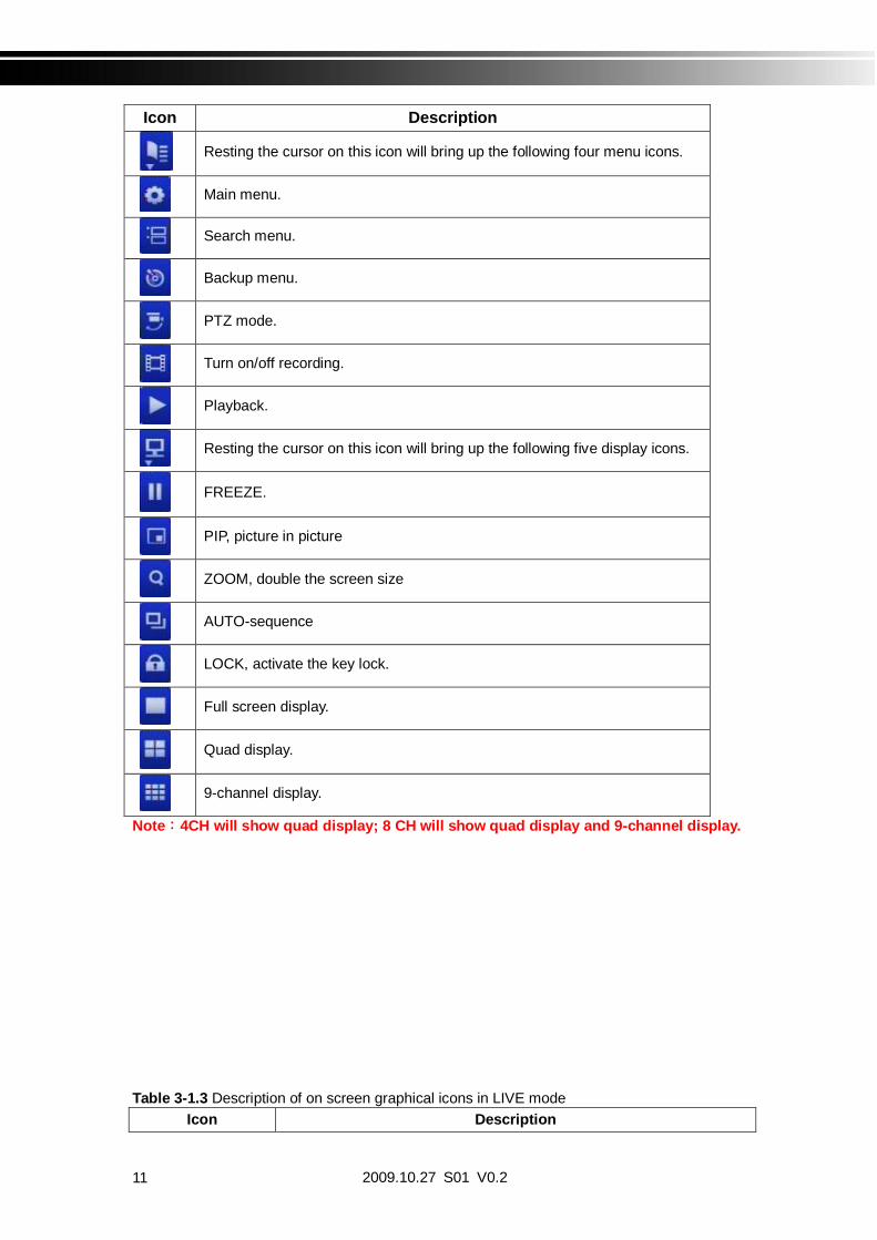
Icon Description
Resting the cursor on this icon will bring up the following four menu icons.
Main menu.
Search menu.
Backup menu.
PTZ mode.
Turn on/off recording.
Playback.
Resting the cursor on this icon will bring up the following five display icons.
FREEZE.
PIP, picture in picture
ZOOM, double the screen size
AUTO-sequence
LOCK, activate the key lock.
Full screen display.
Quad display.
9-channel display.
Note 4CH will show quad display; 8 CH will show quad display and 9-channel display.
Table 3-1.3 Description of on screen graphical icons in LIVE modeIcon Description
2009.10.27 S01 V0.2 12
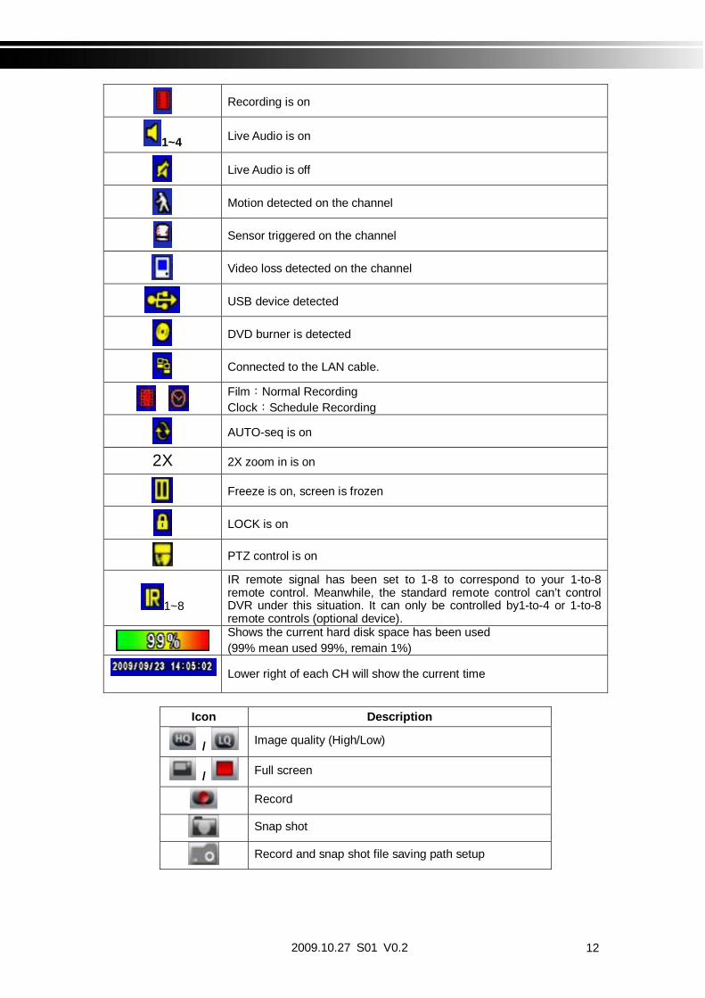
Recording is on
1~4 Live Audio is on
Live Audio is off
Motion detected on the channel
Sensor triggered on the channel
Video loss detected on the channel
USB device detected
DVD burner is detected
Connected to the LAN cable.
Film Normal RecordingClock Schedule Recording
AUTO-seq is on
2X 2X zoom in is on
Freeze is on, screen is frozen
LOCK is on
PTZ control is on
1~8
IR remote signal has been set to 1-8 to correspond to your 1-to-8remote control. Meanwhile, the standard remote control can’t controlDVR under this situation. It can only be controlled by1-to-4 or 1-to-8remote controls (optional device).Shows the current hard disk space has been used(99% mean used 99%, remain 1%)
Lower right of each CH will show the current time
Icon Description
/ Image quality (High/Low)
/ Full screen
Record
Snap shot
Record and snap shot file saving path setup

2009.10.27 S01 V0.213
3-2 PLAYBACK Mode
Switch to PLAYBACK mode by pressing “PLAY” under the LIVE mode, the graphical iconwill show up on the upper center of the screen and the operation panel ( see below picture) willshow up at right lower corner of the screen. You can drag the panel by mouse to place it onany location of your screen.
Table 3-2.1 Remote control functions under the PLAYBACK mode
Button DescriptionENTER / MODE Switch to full screen, quad, 9-channel or 16-channel display.MENU / Turn on/off PAUSE.PLAY Play back at normal speed. / SLOW Play back at slower speed. The speed will be slowed to 1/2, 1/4, 1/8,
1/16 by each pressing of the button till the slowest limitation of 1/16 ofthe normal speed. Current playback speed is shown in the uppercenter of the screen.
/ Fast rewind. Each press increases the speed to the next level. Thereare six speeds: 2x, 4X, 8X, 16x, 32X and 64X.
/ Fast forward. Each press increases the speed to the next level. Thereare six speeds: 2x, 4X, 8X, 16x, 32X and 64X.
/ Stop playback.

2009.10.27 S01 V0.2 14
Table 3-2.2 The mouse operation under the PLAYBACK mode.
Icon Description
/ Fast rewind
/ Fast forward
Play/pause
/ SLOW slow playback
/ stop playback
Playback channel by channel with snap shot display
Full screen display
Quad display
9-channel display
Zoom-in display
Note 4CH will show quad display; 8 CH will show quad display and 9-channel display.

2009.10.27 S01 V0.215
3-3 PTZ Mode
Switch to the PTZ mode by pressing “PTZ” button under the LIVE mode. The PTZ iconwill appear on upper left side of screen and the control panel will appear on the down right sideof screen.
Table 3-3.1 Remote Control functions under the PTZ modeButton Description
/ SLOW Move PTZ up. / Move PTZ down. / Move PTZ to the left. / Move PTZ to the right.ZOOM + PTZ zoom-in.ZOOM - PTZ zoom-out.FOCUS + PTZ focus-in.FOCUS - PTZ focus-out.IRIS + PTZ iris-open.IRIS - PTZ iris-close.
TOUR Activate PTZ pre-set tour.
PRESET+Number
Setup the Preset locationPress “PRESET” key first then two-digit number; DVR will set the currentPTZ location at entered preset number.
PLAY+Number
Go to Preset locationPress “PLAY” key first then two-digit number, PTZ will go to thecorrespondent preset number location.
PIP Set current PTZ location as the start of line-scan.
FREEZE Activate auto line-scan.
ZOOM Set current PTZ location as the end of line-scan.PTZ communication protocols from different brands aren’t compatible 100% sometimes. Therefore, some of these functions may be unavailable.

2009.10.27 S01 V0.2 16
Table 3-3.2 Mouse operation under the PTZ mode
Icon Description
Leave PTZ Mode back to the LIVE mode
Pre-set number N. (1~64)
Go to pre-set number N.
Set current PTZ location at pre-set number N.
TOUR press to activate pre-set tour
PIP Set current PTZ location as the start of line-scan.
FREEZE Activate line-scan.
ZOOM Set current PTZ location as the end of line-scan.
To move PTZ in 360°
PTZ zoom in; PTZ zoom out
PTZ focus in; PTZ focus out.
PTZ IRIS open, PTZ IRIS close.
Below functions need support from specific PTZ manufacturer. Please check user manual of your PTZ for more detail.
to AUX 1~8, AUTO Key Number key 1~8
Backup , Customized function
PTZ communication protocols from different brands aren’t compatible 100% sometimes. Therefore, some of these functions may be unavailable.

2009.10.27 S01 V0.217
CHAPTER 4 MAIN MENU SETUPTo enter the main menu and set up DVR, log-in account and user password are required.The default password of the administrator is “123456”. Please check the “Account Setup” forrelated setup of other log-in users.
Table 4-0.1 Some definition of virtual keyboard.
Item Description
Switch between capital and small letters.
/ Switch between numbers and letters.
Press to cancel the setup, and re-choose the loginaccount.
Delete the last character.
Enter to identify the password. It will enter the setup menu, If the password is verified.
Space key

2009.10.27 S01 V0.2 18
Table 4-0.2 The operation of remote control under the setting menu
Item DescriptionSwitch to different options under one itemSwitch to different items
MENU Save setup and back to LIVE modeESC Back to Upper level of menu without savingENTER Enter the menu, or display virtual keyboard
PS. The initialization of new-installed HD is required before recording, please refer to “4-9UTILITY SETUP” for detail.
4-1 RECORD SETUP
Item Description
HDD FULL
Select STOP to stop recording or OVERWRITE to reuse theHDD when HDD is full
Stop Stop Recording
Overwrite Start to overwrite that begin from the oldest dataof HDD, and continue to record.
Quality & Frame RateSetup
Setup the quality and frame rate for each channel under normalrecording and event recording type.
OSD position X Setup OSD X axis
OSD position Y Set up OSD y axis
Recording OSDposition setup
Set up OSD axis
2009.10.27 S01 V0.219
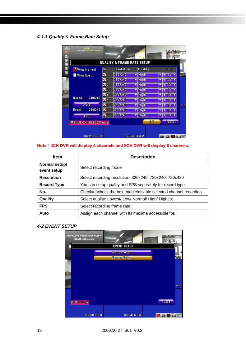
4-1.1 Quality & Frame Rate Setup
Note 4CH DVR will display 4 channels and 8CH DVR will display 8 channels.
Item DescriptionNormal setup/event setup Select recording mode
Resolution Select recording resolution: 320x240, 720x240, 720x480
Record Type You can setup quality and FPS separately for record type.
No. Check/uncheck the box enable/disable selected channel recording
Quality Select quality: Lowest/ Low/ Normal/ High/ Highest
FPS Select recording frame rate.
Auto Assign each channel with its maxima accessible fps
4-2 EVENT SETUP

2009.10.27 S01 V0.2 20
Item DescriptionMotion Setup Enter to set up motion detection
Sensor Setup Enter to set up sensor detection
4-2.1 MOTION SETUP
Item Description
Motion PopupCheck the box to Enable/Disable popup screen function for allchannels. When motion is detected in LIVE mode, thedetected channel image will pop up in full screen display.
1~8 You can setup independently for each channel.
Selected Channel Turn Check the box to Enable/Disable motion detection for eachchannel.
Object Size
Drag the white bar or press to set up Object Size from value 1 to 15 for each channel. The lower valueyou set the higher sensitivity it will be. Value set up as 1, the motion will be detected easiest.
SensitivityDrag the white bar or press to set up Sensitivity from value 1 to 15 for each channel. The lower value you set the higher sensitivity it will be
Motion Area Setup Enter to setup motion detection area

2009.10.27 S01 V0.221
4-2.1.1 MOTION AREA SETUPThe motion detection has been divided into 16x12 grids. The default detection area is full screen as it marked in transparent for local DVR and purple for remote access.Areas deselected for motion detection are marked in red for both local and remote site.
Item DescriptionMask Mouse Selection Switch between “select” and “deselect” for cursor-dragging function
All Area Detection Select entire screen as detection area.
Mask All Area Deselect entire detection area.
Continue Continue setup
Exit & Save Save setup and leave
Exit & Discard Cancel setup and leave
4-2.2 SENSOR SETUP

2009.10.27 S01 V0.2 22
Item DescriptionSensor Popup Check the box to Enable/Disable popup screen function for all
channels. When Sensor is detected in LIVE mode, the detectedchannel image will pop up in full screen display.
All Off Set all sensor off
All Low Set all sensor polarity low
All High Set all sensor polarity high
Sensor Polarity Click or press to select between HIGH, LOW voltage fortriggering sensor detection or OFF to turn off polarity for eachchannel
Low Polarity Sensor has not been triggered. When connected,sensor will be turned on..
High Polarity Sensor has been triggered. When connected, sensorstatus will be turned off..
Off Sensor is deactivated, and will not be turned on/off.
Note 4CH DVR will display 4 channels and 8CH DVR will display 8 channels.
4-3 SCHEDULE SETUPExcept from starting recording manually, you can also setup the recording time by weeks and schedule including normal, motion detect, and sensor detect recording type.
Item DescriptionPage Each page provides 10 schedules for setup. 5 pages in total.
Holiday Setup Enter to setup holiday, up to 50 days, other than weekends,.
View Event/ Motion/Sensor Setup
View Normal/ Motion / Sensor Setup

2009.10.27 S01 V0.223
4-3.1 Schedule Record SetupClick on the time on the left side. The setup menu will be displayed. You can havedetail setup by dates, Time and event.
4-3.2 Holiday Setup
Since holidays are different by different country and region, you can setup the holiday of your location accordingly.

2009.10.27 S01 V0.2 24
4-4 CAMERA SETUP
Item Description1~8 You can setup independently for each channel.
Mask Check the box to Enable/Disable mask function for LIVE mode
SharpnessDrag the bar or press to adjust Sharpness of your camera fromvalue 1 to 255. The default value is 128.
BrightnessDrag the bar or press to adjust Brightness of your camera fromvalue 1 to 255. The default value is 128.
ContrastDrag the bar or press to adjust Contrast of your camera fromvalue 1 to 255. The default value is 128.
SaturationDrag the bar or press to adjust Saturation of your camera fromvalue 1 to 255. The default value is 128.
HueDrag the bar or press to adjust Hue of your camera from value 1to 255. The default value is 128. ( This function doesn’t support atPAL system)
Name Set up name of each channel
Volume Audio volume for CH1 to CH 4 under LIVE mode and recordingmode can be adjusted.

2009.10.27 S01 V0.225
4-5 ACCOUNT SETUPThe Account Setup menu is used to provide role-based permission independently setting foreach user (maximum of 4 users) to access DVR over network. The default admin account andpassword is “admin” and “123456” The default password remains the same after firmwareupgrade, however, it requires 8-digits for password length when you setup a new one
Item DescriptionNo. Check to activate the user’s account.Username Set up usernamePassword Set up password for each user. Password is 8-digits required and can
be mixed by letters and numbers with case-sensitive. Letters can bemixed with capitals or lowercases.
Permissions Set up Permissions for each userChange AdminPassword Change administrator’s password
Picture Change user’s picture
2009.10.27 S01 V0.2 26
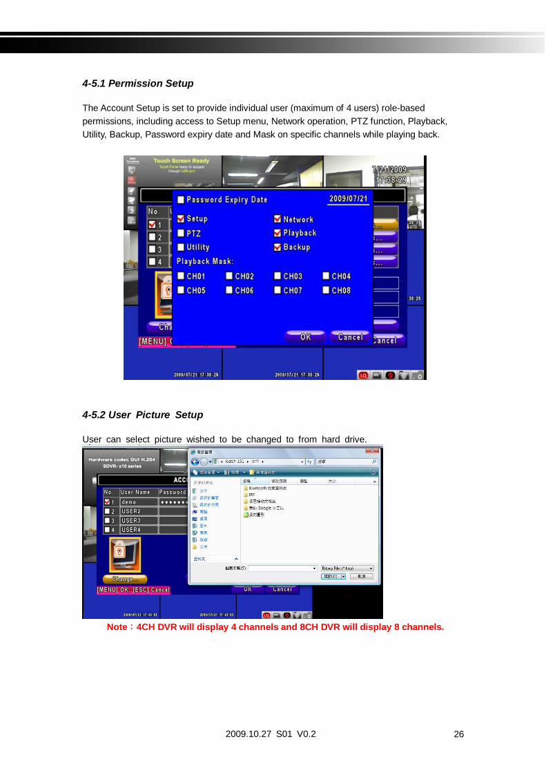
4-5.1 Permission Setup
The Account Setup is set to provide individual user (maximum of 4 users) role-basedpermissions, including access to Setup menu, Network operation, PTZ function, Playback,Utility, Backup, Password expiry date and Mask on specific channels while playing back.
4-5.2 User Picture Setup
User can select picture wished to be changed to from hard drive.
Note 4CH DVR will display 4 channels and 8CH DVR will display 8 channels.

2009.10.27 S01 V0.227
4-6 NETWORKING SETUP
4-6.1 NETWORKING SETUPThere are three ways to connect to the network as followed.
4-6.1.1 DHCPWhen DHCP is selected, IP address will be assigned by DHCP server automatically.
Item DescriptionConnect type Setup mode for network connection: (DHCP LAN ADSL).
HTTP Setup Enter to set up HTTP
DDNS Setup Enter to set up DDNS
Mail Setup Enter to set up mail

2009.10.27 S01 V0.2 28
4-6.1.2 LANSelect LAN for network connection, the following information is required.
Item DescriptionIP Address Enter IP address provided by ISPSubnet Mask Enter IP address of Subnet Mask provided by ISPGateway Enter IP address of Gate way provided by ISPDNS Enter DNS address provided by ISP.
(Note: The correct DNS address must be entered for DDNS function).
4-6.1.3 ADSLSelect ADSL for network connection, the following information is required.
Item DescriptionUser Name Enter user name provided by ISPPassword Enter password provided by ISP

2009.10.27 S01 V0.229
4-6.2 HTTP Setup
Item DescriptionEnable HTTPServer
Check to enable HTTP server. Users can remotely access into theDVR over the network if the HTTP function is activated.
Port Enter a valid port value from 1 up to 65000. The default value is 80.Auto Assign each channel with its maxima accessible fpsNo. Chanel numberQuality Set up record quality. There are below basic, basic, normal, high,
highestFPS Set up record FPS
4-6.3 DDNS Setup
2009.10.27 S01 V0.2 30
Item DescriptionEnable DDNS Enable/disable DDNS function.DDNS Server Enter the registered SMTP Server:
DYNDNS.ORG NO-IP.ORG CUSTOM.COM 3322.ORGI-DVR.NET
SMTP Server Enter the completed registered SMTP Server. (Including username+ Server) If the user name is h.264 and you choose i-dvr as yourserver, you should enter: h.264.i-dvr.net
User Name Enter user name.Password Enter password.
For more detailed I-DVR.NET operation instruction, please refer to appendix I.
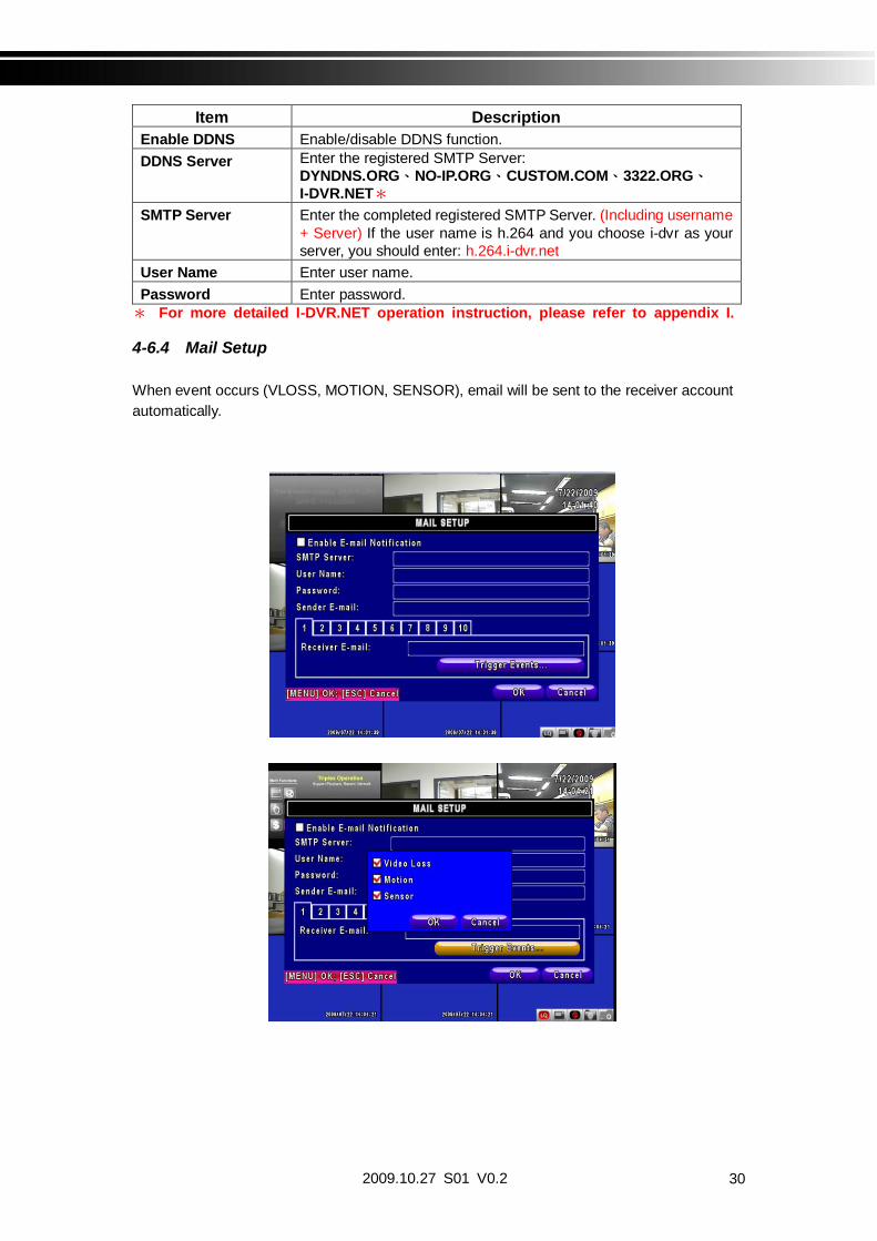
4-6.4 Mail Setup
When event occurs (VLOSS, MOTION, SENSOR), email will be sent to the receiver accountautomatically.

2009.10.27 S01 V0.231
Item DescriptionEnable E-mailNotification
Check the box to enable/disable E-mal Notification function.
SMTP Server Enter to set up SMTP Server name. (Varies according to the user)
User Name Enter to set up User Name.
Password Enter to set up Password.
Sender E-mail Enter to set up e-mail address of receivers.
Receiver E-mail Enter to set up e-mail addresses for up to 10 receivers individually.
Trigger Event Enter to select events to send out E-mail notifications when belowcircumstances happen: Motion, Sensor and Vloss (Video Loss).
4-7 PTZ & RS485 SETUPThe DVR allows users to control PTZ functions of your camera. To enable PTZ function, the 485cable should be connected to the RS-485 port of DVR.
Item Description
Enable PTZ Click the box to Enable/Disable PTZ function for each channel.
Protocol Set up the protocol of PTZ cam. The supported protocol arePELCO-P, PELCO-D, KND, LI-LIN, SAMSUNG, LG, AVTECH.
PTZ ID Click or press to set up PTZ ID. The valid ID value is from 1to 64.
Baud Rate Select Baud Rate for PTZ from 2400, 4800, 9600
RS-485 ID Select RS-485 ID from 1 to 64
RS-485 Baud Rate Select RS-485 Baud Rate from 2400. 4800, 9600
Keyboard Select Keyboard. (Li-Lin)Note 4CH DVR will display 4 channels and 8CH DVR will display 8 channels.

2009.10.27 S01 V0.2 32
4-8 SYSTEM SETUP
Item Description
DVR Name The name of DVR will be shown when users login from remote access.
DVR Location The location of DVR will be shown when users login from remote access
LanguageClick or press to select OSD language from English, TraditionalChinese, Simplified Chinese, Japanese, Greek, Portuguese
Remote ID
Default ID is 1. When DVR is controlled by standard remote control,please press “DVR1 ” before using it. When more than one DVRsare purchased, the DVRs can be numbered from 1 to 4. Forinstance, standard remote control can’t operate DVR numbered 3. Itonly responds when “DVR3” button has been pressed beforehand.
Display Setup Enter to set up Display
Date/Time Setup Enter to set up Date/Time
Device Setup Enter to set up Buzzer & Relay
Spot Setup Enter to set up Spot
Default ID is ID1. If remote control malfunctions, please press, “DVR1” button torenew corresponding DVR ID.

2009.10.27 S01 V0.233
4-8.1 DISPLAY SETUP
Item DescriptionAuto-Seq Interval Set up duration time in seconds for the interval between channels
under Auto-Seq mode.
Show OSD Turn On / Off OSD display
Show DVR Status Turn On / Off DVR illustration and record status display
Show Date/Time Turn On / Off date and time display
Show Channel Name Turn On / Off channel name display
Deflicker Auto Detect Color
Border Color Set up the color of border in LIVE , PLAYBACK mode. Red,Green, Blue
2009.10.27 S01 V0.2 34
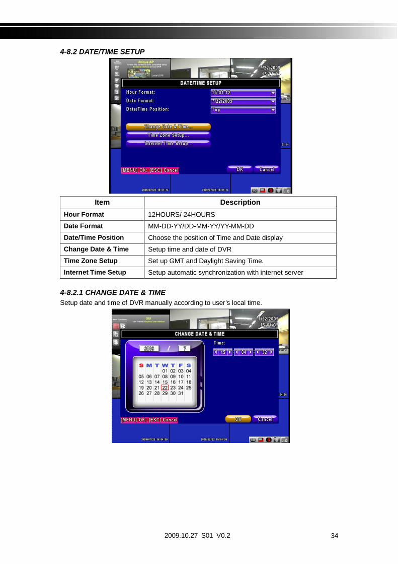
4-8.2 DATE/TIME SETUP
Item DescriptionHour Format 12HOURS/ 24HOURS
Date Format MM-DD-YY/DD-MM-YY/YY-MM-DD
Date/Time Position Choose the position of Time and Date display
Change Date & Time Setup time and date of DVR
Time Zone Setup Set up GMT and Daylight Saving Time.
Internet Time Setup Setup automatic synchronization with internet server
4-8.2.1 CHANGE DATE & TIMESetup date and time of DVR manually according to user’s local time.

2009.10.27 S01 V0.235
4-8.2.2 TIME ZONE AND DAYLIGHT SAVING TIME SETUPSet up time zone and activate Daylight Saving Time function according to user’s DVR location.
Item DescriptionSelect Time Zone Enter to modify GMT from GMT- 13 to GMT+ 13
Daylight Saving Time Turn on/ off Daylight Saving Time
4-8.2.3 INTERNET TIME SETUPSynchronize your DVR time with internet time server.
Item Description
AutomaticSynchronization
Check to enable DVR automatic synchronization function.Effective by this option selected, DVR will automaticallysynchronize the time upon rebooting or by every 24 hours afterbooting.
Update Now Effectively, Date and Time show on DVR will immediatelycorrespond with those in internet server.

2009.10.27 S01 V0.2 36
4-8.3 BUZZER & RELAY SETUP
Item DescriptionKey Tone Enable/Disable keystrokes.
Buzzer Enable/Disable buzzer operation when the alarm is triggered forsensor, motion and vloss (Video Loss).
Relay Enable/Disable the signal to be sent to the RELAY OUT blockswhen the alarm is triggered for sensor, motion and vloss.

2009.10.27 S01 V0.237
4-8.4 SPOT SETUP
The DVR has two modes of video output; one is main video output, the other is spot videooutput. SPOT setup is for controlling the order of channels the system cycles through in SPOTmode. User can monitor every channel in the SPOT mode.
Item Description
SPOT MODE
Channels display in spot for three different modes:MANUAL: select channels to display manually.
SEQUENCE: Auto-sequence for all channels in order.
EVENT: Display channels with event occurred.
Interval (Seconds) The duration time in seconds for the interval between channels underSPOT mode.
Skip Video LossChannel
Whether to skip channels without video signal.

2009.10.27 S01 V0.2 38
4-9 UTILITY SETUP
Item DescriptionHDD Initialization Select to enter hard disk initialization menu. Please stop
recording before entering this menu. Enter the menu,system will show all the data (model ,volume ) of HDD thatinstalled in DVR. Check the HDD you’d like to initializethen press “Start”. HDD initialization is successful whenthe status shows “Succeed”
USB Initialization Clean up all data on USB. Enter USB initialization andpress YES to clean up all data on your USB. Theinitialization is done when it’s showed “Succeed”.
System Recovery Restore system default values
Reset System Events Reset all the recording events in DVR.
Copy Setup to USB Copy configuration to a USB device. There will be a filenamed “sdvr.config” on your USB.
Download Setup from USB Download configuration from a USB device into DVR.
Upgrade Upgrade DVR through USB.Please stop recording and backup setup configurationbefore upgrading.System will reboot automatically when the upgrade iscompleted.
Notice! DO NOT TURN OFF POWER OR UNPLUG USB DEVICE DURING THE UPGRADEas it may cause incomplete firmware upgrade and damage to the DVR.
2009.10.27 S01 V0.239
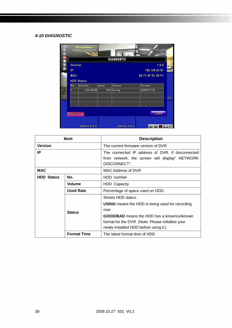
4-10 DIAGNOSTIC
Item DescriptionVersion The current firmware version of DVR
IP The connected IP address of DVR. If disconnectedfrom network, the screen will display” NETWORKDISCONNECT”.
MAC MAC Address of DVR
HDD Status No. HDD number
Volume HDD Capacity
Used Rate Percentage of space used on HDD.
Status
Shows HDD status.USING means the HDD is being used for recordingnowGOOD/BAD means the HDD has a known/unknownformat for the DVR. (Note: Please initialize yournewly-installed HDD before using it.)
Format Time The latest format time of HDD

2009.10.27 S01 V0.2 40
CHAPTER 5 BACKUP & SEARCH
5-1 BACKUP SETUPUser can backup any segment of recorded data in a specified time frame. To do so, either a CDR/W or storage device, like USB, must be connected to the DVR. Recorded data can alsobackup into NB/PC through our remote access software: DVRemoteDesktop.exe and besaved in your assigned path. The format of backup file is IRF file that can be played by both“DVRemoteDesktop.exe” and “CMS”
Item DescriptionFrom The start time of backup file
To The end time of backup file
Device Select USB, CD/RW or PC as the backup device
Free Space The available space in your backup device. (not available for PC backup)
Refresh Recalculate the available space of backup device. (not available for PC backup)
Required Space Show the size of the backup file
Calculate Calculate the size of backup file
StartStart backup operation.Be sure to calculate the size of backup file BEFORE operating backup.
Note! Do not unplug the USB device or turn off the DVR during the backup process toavoid unrecoverable error.

2009.10.27 S01 V0.241
5-2 SEARCH SETUP
Item DescriptionEvent Search Event search menu
Time Search Enter time search menu
5-2.1 EVENT SEARCH
The DVR automatically records events with type, time and channel information included. If there
is recording data for an event, a yellow signal will be shown on the left side of timeinformation. Rest your cursor under the line and press “enter”, or left click your mouse toplayback the recording data.P.S. Event Records will still be generated even when hard disk is not installed or therecord function is not activated. However, the record can’t be viewed after selecting it.

2009.10.27 S01 V0.2 42
Item DescriptionCriteria Setup conditions of event searchPage Switch between pages of eventsDate/Time Date/time when event occurred.
Event Type
Event type, defined as followingVLOSS Video Loss
MOTION Motion Detected
SENSOR Sensor Detected
REMOTEIN user log-in over the network
REMOTEOUT user log-out over the network
POWER ON System Reboot
KEY LOCK System key locked
KEY UNLOCK System key unlocked
System Errors Other error message
Info The channel where event occurs or login user5-2.1.1 CRITERIA SETUP FOR EVENT SEARCH
The amount of events can be numerous. Therefore, you can facilitate event sorting by settingup “criteria”. Setup “start time” and “end time” for event search, then the search result will belimited to this specific period of time. Only checked events and channels will be sorted in eventsearch.
Note 4CH DVR will display 4 channels and 8CH DVR will display 8 channels.

2009.10.27 S01 V0.243
5-2.2 TIME SEARCH
TIME SEARCH can search for the specific time of recording data to playback. Press “Enter” orleft click on the desired date to playback. Note that dates with recording data are marked with ared square “ “System will start playing back according to the date you selected. Calendarwill be shown by using mouse to click on “year” and “month”.
Click “date” to display recording time of that specific date with time bar. You can change time(hour/minute/second) or click on a specific time of time bar by mouse then press “ok”. DVR willplayback the selected recording data.
AP software: DVR Remote Desktop can allow you to remotely access and control the DVRfrom PC.

2009.10.27 S01 V0.2 44
5-3 AP Software Installation and Setup
AP software: DVR Remote Desktop can allow you to remotely access and control the DVRfrom PC.p.s. Operation system currently supports Windows XP SP2 and above and Windows Vista
Step One Enter the IP address of DVR in IE browser
Step Two: Windows as below will show up. Please enter the user name and password. Defaultuser name and password is admin/123456. Other related setup about user accountand password, please check “4-5 Account Setup. “
Step Three: Click on the link to start downloading the AP software.

2009.10.27 S01 V0.245
Step Four: Run or Save our AP software.
Step Five: If you choose to run the software, Start window will be shown up. Please enterinformation of login DVR: IP, Port, Username and Password, or choose “PlayRecorded File” to open backup files in your PC.
Step Six: You’ve logged into the DVR
Note 4CH DVR will display 4 channels and 8CH DVR will display 8 channels.

2009.10.27 S01 V0.2 46
5-4 How to do remote monitoring through IEStep One Enter the IP address of DVR in IE browser. The address appeared in this image isonly for demonstration. Actual address is depending on the setup of on-site DVR.
Step Two: Windows as below will show up. Please enter the user name and password. Defaultuser name and password is admin/123456. Other related setup about user accountand password, please check “4-5 Account Setup. “ The user name and passwordappeared in this image is only for demonstration. Actual user name and passworddepend on the setup of on-site DVR.
Step Three: Click on “Internet Explorer 6, 7, and 8”to start downloading the AP software. ( Thefirst option is for IE view, please refer to next chapter for more information)
p.s. There will be IE connection security issue when clicking this link for the first time.Please refer to index II for Remote Monitoring IE ActiveX Control Installation Instruction.

2009.10.27 S01 V0.247
Step Four: DVR images appear.
Note 4CH DVR will display 4 channels and 8CH DVR will display 8 channels.

2009.10.27 S01 V0.2 48
5-4 AP Software Operation
Open the file “DVRemoteDesktop.exe”; enter the information of DVR “IP address”, “Port”“Username” and “Password” and click “OK”. You should be able to login DVR successfully andstart to use the software. The default username and password is admin/ 123456
“DVRemoteDesktop.exe” AP software provides some extra functions for remote users.Please check Table 6-2.1 for detail information and Table 6-2.2 for minimum systemrequirements for “DVRemoteDesktop.exe” operation. Table 6-2.3 is corresponding to Ethernetcable bandwidth. Please take this table for future references when applying for Internetbandwidth or connecting to Internet.
Table 5-4.1 Toolbar of AP software
File - Record to Local Record data to your PC, including LIVE andPlayback.
File - Play Recorded Files Play recorded files “.irf”File - Exit Alt + F4 Close the AP software.
Edit - Channel Name F2 Edit channel name of your DVR including font,size italic, and boldface of characters. .
Edit - Reset Channel Name Reset channel name back to default.View - Hide Caption & Menu F9 Hide the Caption and MenuView - Disable resizing F10 Disable the function of resizing window.View - Full screen F11 Switch it to full screenView- Render Filter Unable/ Disable the Bilinear function
View- Play All FramesUnable this function will stop the audiotransmission in order to improve the playbackspeed quality.
View- Language Switch between languages for toolbar
Help – About Show information about software andinformation
Table 5-4.2 System Requirements for AP softwareCPU Intel Pentium 4 aboveOS Microsoft Windows Vista Windows XP SP2 aboveRAM 512M aboveVGA Card Needed to support DirectX9.0 (Above) Note 1Others DirectX 9.0 above
Note 1:Known VGA card that support DirectX9.0 currently:NVIDIA: Geforce FXseries, Geforce 6series, Geforce 7series, Geforce 8series, Geforce
9series, Geforce 200series, etc. Or
visit:http://en.wikipedia.org/wiki/Comparison_of_Nvidia_graphics_processing_unitsATI: Radeon R300series, Radeon R400series, Radeon R500series, Radeon R600series,
Radeon R700series, Radeon HD 3xxx IGPseries, Mobility Radeonseries (9500above), Mobility Radeon Xseries, Mobility Radeon HDseries, or FireGL Vseries etc.Or visit: http://en.wikipedia.org/wiki/Comparison_of_ATI_graphics_processing_units
SiS: SiS 67Xseries, or SiS 77Xseries etc.Or visit: http://www.sis.com/support/support_compare.htm
Intel: 91Xseries, 94Xseries, 96Xseries, G3Xseries, or G4Xseries, etc.Or visit: http://en.wikipedia.org/wiki/Intel_GMA

2009.10.27 S01 V0.249
CHAPTER 6 SPECIFICAITONS
1. VIDEOInput Level 1.0 Vp-p±10% Composite, 75 Balanced
Display SpeedNTSC 480 fps(16CH), 240fps(8CH), 120fps(4CH)
PAL 400 fps(16CH), 200fps(8CH) , 100fps(4CH)
Display ResolutionNTSC 720(H) X 480(V)
PAL 720(H) X 576(V)
Monitor Output 2Vp-p Composite, 75 Balanced
2. RECORDINGCompression Method H.264
Recording Speed Refer to table 7-1
Recording ResolutionNTSC 720 X 480, 720 X 240, 352 X 240
PAL 720 X 576, 720 X 288, 352 X 288
Quality Independent foreach channel
Lowest/ Low/ Normal/ High/ Highest
Schedule Setup by “minute” as unit
Mode Manual / Event (Motion, Sensor) / Schedule
MethodBy resolution, fps and qualitySetup fps and quality separately for normal andevent recording
3. SATA DEVICE
CapacityInternal Storage
3 HDDs or 2 HDDs + 1DVD-RW (16 CH)2 HDDs or 1 HDDs + 1 DVD-RW (4CH/ 8CH)
External Storage 1 HDD
Type SATA / SATA compatible
External Bay Interface E-SATA
4. ALARMSensor Input 16(16CH), 8(8CH), 4(4CH)Loop Out 1 Relay out
Motion Detection Available per each camera/ Multi-detection level
5. CONNECTIONS
Video Input BNC 16 ports (16CH), 8 ports (8CH), 4 ports (4CH)
Video Output BNC 2 port, VGA 1 port (Optional)
Audio Input RCA 4 CH
Audio Output RCA 1 CH
USB 2.0 USB memory stick, USB Mouse, USB Touch Panel
Remote Remote control, 1-to-8 remote control (optional)
External I/O1 RS-485, 16(16CH) / 8(8CH) / 4(4CH) sensor input,1 Relay Output
Ethernet 1 RJ45 connector, 10/100 Mbps
6. ELECTRICAL
Power SourceDC 12V / 6.25A (16CH) ,DC 12V / 5A (8CH) , DC 12V / 5A (4CH)

2009.10.27 S01 V0.2 50
7. ENVIRONMENTAL
Operation Temperature 5 ~ + 40
Humidity Less than 90%
8. PHYSICALDimension 430(W) x 293(D) x 55(H) mm
Weight 2.5kg (3.5kg including 1 HDD and CD-RW)
9. BACKUP
BACKUP
USB Stick Video Data, Audio
CD-RW/DVD±RW Video Data, Audio
Network Video Data, Audio
10. SEARCHING & PLAYBACKSearching Type Event/ Time
Playback speed 120 FPS11. MULTI-REMOTE SURVEILLANCE Monitoring Environment Web / Client Software(CMS)
Max. client Supporting multi-client (5 clients accessible)
12. OTHERS OS Embedded Linux
Multi Task Pentaplex Live Record Playback Network Backup
Control DeviceFront Keys / Remote Control / 1-to-8 RemoteControl (Optional)Virtual Keyboard / Mouse / AP Software
PC Viewer Direct monitoring of DVR’s HDD on PC
Numbers of event list 10240
Table 6-1
RecordingSpeed(Independentsetting for eachchannel)
NTSC
352 x 240240fps / 16CH, 8CH120fps / 4CH
720 x 240120fps / 16CH, 8CH60fps / 4CH
720 x 48060fps / 16CH, 8CH30fps / 4CH
PAL
352 x 288200fps / 16CH, 8CH100fps / 4CH
720 x 288100fps / 16CH, 8CH50fps / 4CH
720 x 57650fps / 16CH, 8CH25fps / 4CH
Compression Method H.264

2009.10.27 S01 V0.251
CHAPTER 7 MOBILE APPLICATION INSTALLATION AND USAGE
You can remotely monitor all channels of DVR through your mobile device. The required mobileapplication is from DVR manufacturer and it supports mobile OS for both Windows mobile 5.0above and Symbian.
Please confirm network function of DVR has been activated before mobile connection:Main menu Network Setup HTTP Setup Check the “Enable HTTP Server”
7-1 Mobile Application Installation and Operation for Symbian System
Mobile Device: Nokia, SonyEricsson…etc.
System requirement:GPRS/ 3G must be provided from your telecom service.Mobile device that supports GPRS/ 3G protocol and Java cldc1.0/midp 2.0 environment
Please download both” DVRH264.jar” and “DVRH264.jad” to operate the function. Note that users with Sony Ericsson will only need to download “DVRH264.jar.”
7-1.1 Mobile Application Installation
Please follow the steps cited below to perform the mobile device surveillance function.
Step 1: The mobile application called “DVRH264.jar” need to be installed in your mobile device.The application can be downloaded directly from the manufacturer’s website to yourmobile or; alternatively, it can be transferred to your mobile device from the CD thatpacked with DVR through Bluetooth or USB cable.
Step 2: Install the application software “DVRH264.jar” in your mobile device. It might beinstalled automatically after downloading; otherwise, select it from the downloading filefor installation.

2009.10.27 S01 V0.2 52
7-1.2 Mobile Application Operation
After the installation, enter the Program Files menu inyour mobile device to run a file called “DVRH264”.
Select “Menu” at the right lower corner of your mobilescreen, 4 commands, Login Add Modify and Delete,will show up.
7-1.2.1 Add New Login DVR
To log into the DVR, you need to enter the logging-inDVR information. Find “Add” under the “Menu” thenenter logging-in DVR’s IP address, Port number,account name and password. Press “Add” to save thisinformation after entering.
7-1.2.2 Logging Onto the DVR
Use the Login command to log onto a DVR and monitorlive images. If multiple DVRs have been added to themobile application, they will be listed by name, you canselect one to log onto.
A confirmation message might show up for network chargebefore connection. The fee rate will depend on the telecomcompany and package fee you go with.
Network connectivity will take some time. It’ll be affected bynetworking environment and bandwidth flow.Live image will show up after a successful connection.
PS. The Live can not be displayed in your mobilewhen the recoding is off in local DVR.

2009.10.27 S01 V0.253
7-1.2.3 Modify the Login Information of DVR
You can use the “Modify” command to change the login information of DVR. The dialogue isidentical to that of the “Add” command.
7-1.2.4 Delete the Login Information of DVR
“Delete” command can be used to remove the DVR information if it is no longer useful. Selectthe DVR on the name list then choose “Delete”
7-1.3 Live Monitoring Operation
This paragraph describes some operation under the LIVE monitoring mode in your mobiledevice.

2009.10.27 S01 V0.2 54
7-1.3.1 Scroll the Image
You can use the keypad on your mobile device to scroll the image if it’s oversized.
Key Action2 Scroll Up4 Scroll Left6 Scroll Right8 Scroll Down
7-1.3.2 Image Quality Setup
Select “Quality” under the “Menu”
There will be 5 levels for your to choose: LowNormal Middle High and Highest.
7-1.3.3 Channel Display
Select “Single” under the “Menu”, there will be allchannels of your DVR in list for you to choose.
PS. The Live can not be displayed in your mobilewhen the recoding is off in local DVR.

2009.10.27 S01 V0.255
7-1.3.4 Size of Image
The screen size of different mobile device can be different. You can select “Size” under the“Menu” to choose from “Original” or “Fit Screen” to resize the display image.
Item DescriptionOriginal The image will be shown in
original size.Fit Screen The image will be shown to fit the
screen.
7-1.3.5 Rotate the image
The Live image can be displayed in normal or rotate to 90degrees. Select “Rotate” under the “Menu” for thisoperation.
7-1.3.6 Alarm
This application not only allows you to remotely monitor through mobile device but receive thealarm that has been triggered by events such as Motion Detected, Sensor Triggered and Vloss.
Graphical icons below will be shown on the status:
: Motion detected
: Sensor triggered
: Video loss
Select the “Alarm” under the “Menu” to switch thisfunction on or off.

2009.10.27 S01 V0.2 56
7-2 Mobile Application Installation and Operation for Windows Mobile System
There are two kinds of applications for Window Mobile OS: JPEG compression and H.264compression. The one for H.264 compression can transfer both audio and video signal to yourmobile device.
System Requirement:Mobile device OS Windows mobile system 5.0 above.
Mobile device need to support internet: GPRS 3G Wifi… etc.
7-2.1 Mobile Application Installation
Please follow the steps cited below to perform the mobiledevice surveillance function on your mobile device (mobilephone, PDA ...etc).
Step 1: The mobile application called “Jrviewer.CAB” and“H264Pocket.CAB” need to be installed in your mobiledevice. The application can be downloaded directlyfrom the manufacturer’s website to your mobile or;alternatively, it can be transferred to your mobiledevice from the CD that packed with DVR throughBluetooth or USB cable.
Step 2: Install the application software “Jrviewer.CAB” and“H264Pocket.CAB” in your mobile device, two foldersnamed ”Jrviewer” and “H264Pocket” will be created. It might be installedautomatically after downloading; otherwise, select it from the downloading file forinstallation.

2009.10.27 S01 V0.257
7-2.2 Mobile Application OperationAfter the installation, enter the Program Files menu in your mobile device to run files named“Jrviewer” and “H264Pocket”.This application allows you to remotely logon and monitor DVR. Press “OK” to bring up theoperation menu, see below chart to further information.
Item Function Description
Add Add login DVR Enter DVR’s name, IP address, Port, Account user, Passwordthen press “OK”
Login Logon DVR
Choose the DVR that you’d like to log on , then press “OK”PS. The Live can not be displayed in your mobile
when the recoding is off.PS. Network connectivity will be affected by networking
environment and bandwidth flow. The fee rate willdepend on the telecom company and package feeyou go with.
ModifyModify LoginDVR
Choose DVR, press “Modify”, and press”OK” to save change.
DeleteDelete LoginDVR Choose DVR and press ”Delete” to delete the DVR info.
The operation of Jrviewer The operation of H264Pocket
7-2.3 Operation under the LIVE monitoring.After successful logon the DVR, press “View” to bring up operation menu. You can
choose the channel, resize the image, choose the quality, and turn on/off the status bar, alarm, full screen display….etc

2009.10.27 S01 V0.2 58
7-2.3.1 Operation uner the LIVE monitoring for Jrviewer
Item Function DescriptionChannel 1~16 Display for CH 1~16 Choose from CH1~16 to display
Screen Size of imageOriginal image size as originalStretch stretch the size as full screenFit: resize the image to fit the screen
Quality QualityChange the quality of image. Please note thebetter quality, the slower data transfer rate.
Status Bar Status Bar
Graphical icons indicated below will be shownon the status bar if there is event such asmotion detected, sensor triggered and videoloss to be detected on any channel. You canalso uncheck the “Status Bar” to inactivatethis function.
Icon Description
Motion Detect
Sensor Trigger
V-Loss
Alarm Alarm
Alarm through your mobile device can betriggered if there is event to be detected. Youcan also uncheck the “Alarm” under the“View” to inactivate this function.
2009.10.27 S01 V0.259
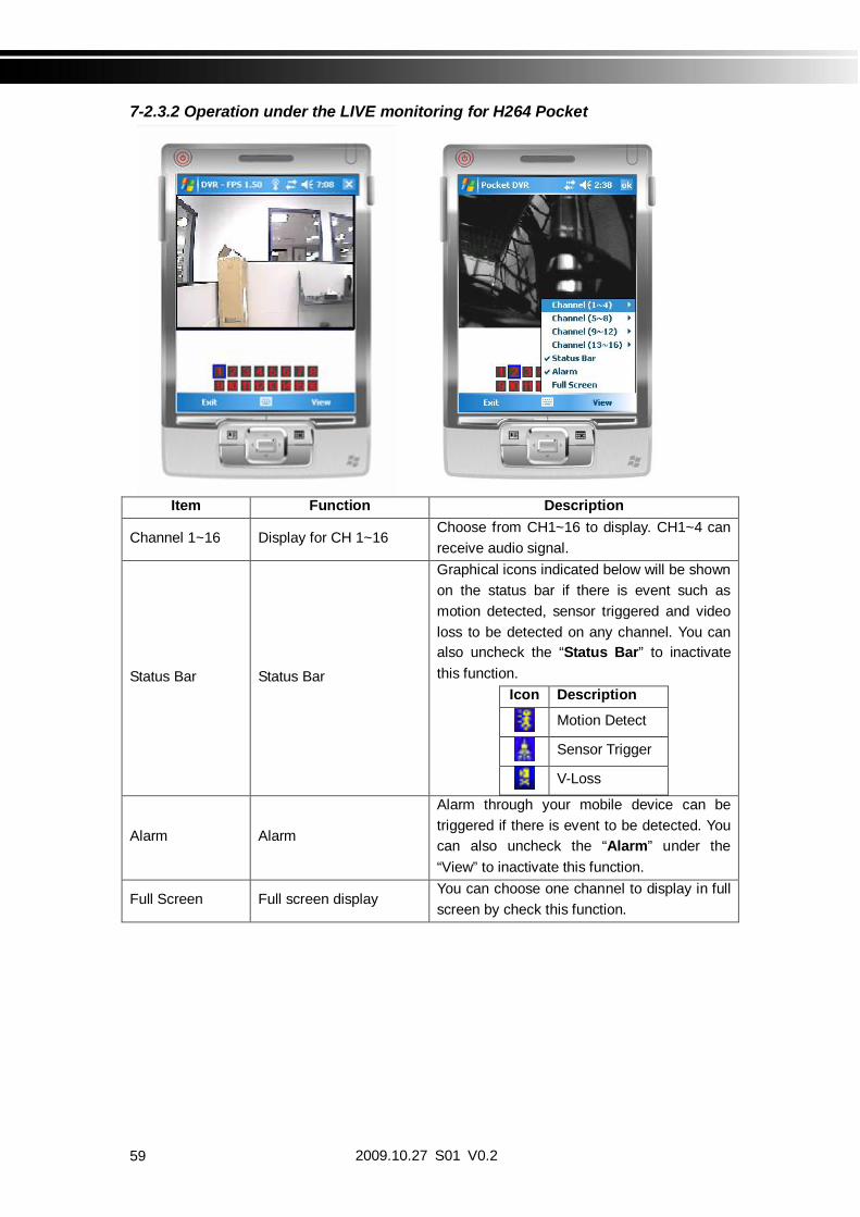
7-2.3.2 Operation under the LIVE monitoring for H264 Pocket
Item Function Description
Channel 1~16 Display for CH 1~16Choose from CH1~16 to display. CH1~4 canreceive audio signal.
Status Bar Status Bar
Graphical icons indicated below will be shownon the status bar if there is event such asmotion detected, sensor triggered and videoloss to be detected on any channel. You canalso uncheck the “Status Bar” to inactivatethis function.
Icon Description
Motion Detect
Sensor Trigger
V-Loss
Alarm Alarm
Alarm through your mobile device can betriggered if there is event to be detected. Youcan also uncheck the “Alarm” under the“View” to inactivate this function.
Full Screen Full screen displayYou can choose one channel to display in fullscreen by check this function.

2009.10.27 S01 V0.2 60
CHAPTER 8 CMS INSTALLATION AND USAGE GUIDE
8-1 CMS Installation
System Requirement:Intel Pentium 4 processor or equivalent.Microsoft Windows Vista Windows XP Windows 2003 Server.Besides OS and other required APs, there will be 512MB remaining memory needed or above.512MB memory above.(500M requested for group DVR connection and 180M for single DVR)20MB HD space. Recording and image capturing require extra space for storage.VGA Card needs to support DirectX9 and function well while running it. Please refer to
p55 Note 1.
Installation:1. Connect to the manufacturer’s website and download the CMS software.2. Decompress and execute “setup.exe”.3. If “Visual C++ Runtime Libraries” has not been installed before in the operating PC, the
following sign will suggest an installation automatically.
4. Select “Next”, and then select “Browse” to change installation path if needed. To checkavailable space on hard disk, please select “Disk Cost” then please select “Next” to thenext step.

2009.10.27 S01 V0.261
5.”Confirm Installation” window shows. Select ‘Next’ then the installation starts.
6. Select ‘Close’ to finish installation when the “Installation Complete” window shows.

2009.10.27 S01 V0.2 62
Instruction for Log-in Failure to CMS After UpgradeLog in to CMS with the default account and password after CMS upgrade. If an error
message occurs as shown in the image, please follow the instruction to solve the error.
Step 1: Please enter file manager to enter folder, “Windows” and then folder “Systme32”(ex:C:\Windows\System32)
Step 2: Locate file, “iCMS.dat” and delete it.
Step 3: Restart CMS. Log-in successfully.

2009.10.27 S01 V0.263
8-2 CMS LOGIN AND ENVIRONMENT
To enter CMS, the administrator’s user name and password are required. The defaults are‘admin’ and ‘123456’.
After successful login, the following image shows on your screen:
DVRs, Groups &Events
Information about DVRs, groups and events.See “9-3 Information List” for more detail.
PC informationand control
Information about local PC’s hard disk, volume, recording...etc.See “9-4 PC Information and Control” for more detail.
Main Display Live image display area. See “9-5 Main Display” for detail.
Display Modes Several choices of display modes supported by CMS.
Operation BarA set of 10 operations are provided by CMS. See “ 9-6 OperationBar” for detail.
:

2009.10.27 S01 V0.2 64
8-3 DVRs, Groups & Events
Icon DescriptionView list of logged in DVR Group.
View Logs: list all the event information of DVR
8-3.1 View DVR Group List
Single left click on ‘DVR’ or ‘Group’ willexpand/collapse the entire DVRs andgroups list.
On the DVR list, double left click on aconnected DVR will show its image inmain display. See “9-6.2 DVRAdministration” for further information.
On the Group list, double left click on agroup will show live image from thechannels of the group in the maindisplay. See “9-6.3 for GroupAdministration” for further information.
Left-clicking on a connected DVR will expand/collapse status of its all channels as below:
Icon Description
Video Loss
Motion Detected
Sensor Triggered

2009.10.27 S01 V0.265
8-3.2 View Event LogsUnder this page, all the events of a DVR can be expanded/collapsed in the order of Remote in/Remote out, Video Loss, Motion, Sensor, Others (Power Reset, Key Lock, KeyUnlock, HD Full).
8-4 Local PC Information and Control
Located at the left lower corner of the screen, please see the chart below:
Icon Function Description
HDD infoShows the ratio of available space / HDD capacity ofC:\ drive (where CMS is installed).
Volume PC volume or playback volume control bar.
RecordingRecord live image to local PC storage. To view locally stored data, use “Record” under theoperation bar. Also see “9-6.6 recording data” for detail.
SnapshotTake snapshot to save in local PC storage. Toview all the snapshots you’ve taken, please goto ” Snapshot” under the operation bar. See “9-6.5 Snapshot data” for detail.

2009.10.27 S01 V0.2 66
8-5 Main Display
The main display area is where the live image of DVR is shown. You can drag to change thelocation of screen for each channel and turn on/off audio signal with mouse-click.
8-5.1 Audio Control
In live mode, you can turn on/off the audio signal of Ch1~Ch4:
Audio signal is On
Audio signal is Off
Turn on/off by clicking on the graphical icon, please note there can allow only one channel’s audio signal to be on at one time.

2009.10.27 S01 V0.267
8-5.2 eMAP Display
In Live mode, pressing will bring the e-MAP drag-down menu. If the channel hasbeen set up to use e-MAP, the menu will show all the e-MAP titles that have beenentitled to this channel; otherwise, “No eMaps” will be shown. Please check “9-6.4eMAP administration” for setup information.

2009.10.27 S01 V0.2 68
8-5.3 PTZ ControlIn the main display, right click on the channel will bring up PTZ control panel as below.
PTZ communication protocols from different brands aren’t compatible 100% sometimes. Therefore, some of these functions may be unavailable.
Icon Description8 direction key Rotate the PTZ
ZOOM+ Zoom in
ZOOM : Zoom out
Setup the PTZ spot as pre-set N.
FOCUS+ : Focus in
FOCUS- Focus out
Move to pre-set N.
Set PTZ Preset Setup 16 pre-set N.Goto PTZ Preset Move to specific pre-set N.
Activate auto pre-set tourPTZ Sensitivity Setup PTZ sensitivity
Setup the “start” and “end” ofliner scan.Activate the liner scan cruise.
Customization functionAUX 1~8 ( For
customization) AUTO+1 ~ AUTO+8

2009.10.27 S01 V0.269
8-6 Operation Bar
10 Operations to be listed as below:
Table 8-6.1 description of 10 operations:Icon Description
User Administration. Please see “8-6.1 User administration”
DVR Administration. Please see “8-6.2 DVR Administration”
Group Administration. Please see “8-6.3 Group Administration”
eMap Administration. Please see “8-6.4 eMap Administration”.
Remote Playback. Please see “8-6.5 Remote Playback”.
HDD Playback. Please see “8-6.6 HDD Playback”
File Playback. Please see “8-6.7 File Playback”
Event Playback. Please see “8-6.8 Event Playback”
Snapshot Data. Please see “8-6.9 Snapshot Data”
Recording Data. Please see “8-6.10 Recording Data”

2009.10.27 S01 V0.2 70
8-6.1 User administrationBefore the CMS can be used on a PC, user accounts should be added with proper authority.Each user should also be assigned a password and optionally a description. If a user does nothave certain authority assigned, he/she will not be able to operate the corresponding functionon the Operation Bar. The default is none of the authority is assigned. The administrator shouldassign proper authority to each user. These user accounts can be deleted or edited later on.
Select “OK” to save the setup.Icon Description
Add a user account. The default authority is with none permission.
Delete a user account.
8-6.2 DVR AdministrationDVR connections can be added to or deleted from the CMS and their information can be edited.DVR’s channel names can be entered here or downloaded from the DVR by pressing ‘FromDVR’. Select “OK” to save the information.

2009.10.27 S01 V0.271
8-6.3 Group Administration
A ‘Group’ means a set of video channels from one or many DVRs, which means, user canorganize channels from different DVRs to be set in a group. This function allows you to monitorand manager channels from multiple DVRs easily and flexible.
Steps:1. Add a new group and set its name and description.2. Click ‘Select’ which will bring up a new window.3. Check the specific channels that you’d like them to be included in the group. To include all
channels of a DVR, just check the DVR.
4. Click “OK” to return to the previous window.5. Select a display mode.6. Drag a channel from the lower left panel into the main display to a preferred location. Or,
change the channel location in the main display by mouse dragging.7. You can ‘Select’ again to add other channels, but the un-saved channel locations will be
lost.8. Click “OK” to save the setup.
2009.10.27 S01 V0.2 72
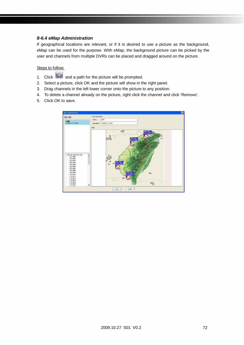
8-6.4 eMap AdministrationIf geographical locations are relevant, or if it is desired to use a picture as the background,eMap can be used for the purpose. With eMap, the background picture can be picked by theuser and channels from multiple DVRs can be placed and dragged around on the picture.
Steps to follow:
1. Click and a path for the picture will be prompted.2. Select a picture, click OK and the picture will show in the right panel.3. Drag channels in the left lower corner onto the picture to any position.4. To delete a channel already on the picture, right click the channel and click ‘Remove’.5. Click OK to save.

2009.10.27 S01 V0.273
8-6.5 Remote PlayVideo images recorded on a DVR can be displayed on a remote CMS. With Remote Playfunction, select a DVR and a display mode on top of the screen. After the recorded segmentsare listed below, double click on one to show its image on the right.
Icon Description
Start playing.
Pause.
Fast forward.
Fast rewind.

2009.10.27 S01 V0.2 74
8-6.6 HDD PlaybackYou can directly play the recording data in the HDD that’s uninstalled from DVR by CMS. Seethe picture below, the left part of screen is recording data in list that’s separated by hour and theright part is main display. You can change the display modes and play files fast forward orrewind.
8-6.7 File Playback
You can play the recorded .irf files by “File Play” in CMS. It allows you to change thedisplay mode, forward or rewind the file and drag the time bar.
Icon DescriptionStart Playback.
Pause.
Stop playback.
Fast forward.
Fast rewind.

2009.10.27 S01 V0.275
8-6.8 Event Playback
Event recordings on the DVR can be played back in CMS.
Steps to follow:1. Select a DVR and a display mode.2. Select a date.3. Double click an event and play back the images on the right.
Use buttons at the bottom to control the playback.
8-6.9 Snapshot DataIt can display all the snapshots you’ve taken in line in “Snapshot Data”. You can review, deleteor save as other files here.

2009.10.27 S01 V0.2 76
8-6.10 Recording DataIt can play all the recording files you’ve recorded in line in “Recording Data”. You can play ordelete them here.
Steps to follow:1. Choose the recording time at upper left corner, it will be played on the main display.2. You can choose the display mode.3. Time bar will be shown at right lower corner, please drag the time bar to specify
the recording time you’d like to play.

2009.10.27 S01 V0.277
APPENDIX I I-DVR.NET REGISTRATIONDDNS Registration on I-DVR.NET
In the package of each DVR, you will find a sticker shows account information includingusername and password that allows users to login I-DVR.NET for registration.
To register DDNS on I-DVR.NET, please follow the steps as shown.
Step 1. Please open IE browser and then enter “ http://i-DVR.NET/logon.asp ” in IE browser bar.Next, “Control Panel Logo” dialog will appear. Enter the username and passwordprovided by the sticker and then press, “Logon.”
Step 2. After login successfully, enter name at “host” in “Add New Record” dialog. For example,“icatchddns” is the host name, and then the address will be “icatchddns.idvr.net.” Select“Standard” type and enter an IP address of the DVR. Input known IP address if any, orpress the “Add New” button if none.
Step 3. The “Host Manager” dialog will show “Your new host record was created” when usersetup successfully. The “host.domain” column will show up the setup just entered.
If DDNS set up at DVR side successfully, the website will update the IP information inone minute. The IP column will be renewed to the corresponding IP address bypressing “F5: refresh” button.
Please enter any name by your choice atColumn, “host.” For example, “icatchddns”Therefore, IE address will be“icatchddns.idvr.net”
System will automatically show the current computer IP. If the DVR IP is known, you can type it in the column. If not, you can press “Add new” button.
“host.domain” is named by your choice.“icatchddns.idvr.net” is what the mainserver generates
If DVR IP has any changes, there are updatesHere at the same time. Press, “F5: Refresh”And then IP column will update automatically to it’s realIP Address.

2009.10.27 S01 V0.2 78
Step 4. Enter DVR Main Menu Network Setup DDNS. Activate DDNS functions andinput related information.
2009.10.27 S01 V0.279
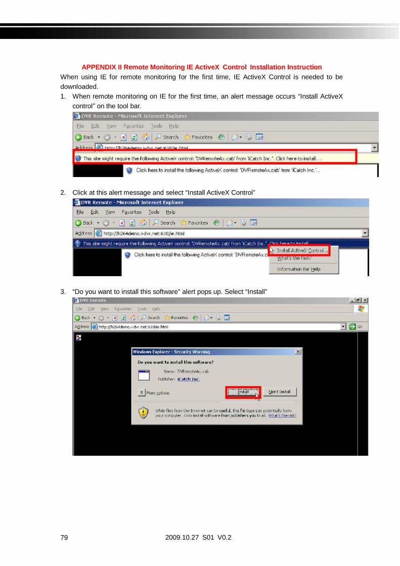
APPENDIX II Remote Monitoring IE ActiveX Control Installation InstructionWhen using IE for remote monitoring for the first time, IE ActiveX Control is needed to bedownloaded.1. When remote monitoring on IE for the first time, an alert message occurs “Install ActiveX
control” on the tool bar.
2. Click at this alert message and select “Install ActiveX Control”
3. “Do you want to install this software” alert pops up. Select “Install”

2009.10.27 S01 V0.2 80
4. After installation, IE remote monitoring image appears.
5. If message, “Your security Settings do not allow web sites to use ActiveX controls installedon your computer.” pops on when logging in, please follow the next instruction.
6. First select “Tools” on the tool bar and then select “Internet Options”

2009.10.27 S01 V0.281
7. Select Security Trusted Sites Sites
8. Enter DVR address (This address is only for demonstration. Please use the addressdepends on the setup of on-site DVR.) into the blanks shown in picture, and then press“add.”

2009.10.27 S01 V0.2 82
9. Newly added website will appear at the trusted web sites list. Press close.
10. Go back to IE window, press refresh button or F5.