48 volt golf car - viewmastercms.com · 48 volt golf car yamaha golf-car company 1000 hwy 34 east...
TRANSCRIPT

48 VOLT GOLF CAR YDRE
LIT-19626-21-09 JW2-F8199-11YAMAHA GOLF-CAR
COMPANY1000 HWY 34 EastNewnan, GA 30265
770-254-4000
Printed in U.S.A2008-KCC
LIT_19626_21_09 cover.qxd:LIT_19626_11_07 cover.qxd 5/12/08 9:31 AM Page 1
INTRODUCTIONCongratulations on your purchase of aYamaha golf car. This manual containsinformation you will need for proper operation, maintenance, and care of yourgolf car. A thorough understanding ofthese simple instructions will help you toobtain maximum enjoyment from yournew Yamaha.
If you have any questions about the operation or maintenance of your golfcar, please consult a Yamaha dealer.
YAMAHA GOLF-CAR COMPANY
YDRE OWNER’S/OPERATOR’SMANUAL
© 2009 by Yamaha Golf-Car Company2nd Edition
All rights reserved. Any reprintingor unauthorized use without the
written permission ofYamaha Golf-Car Company
is expressly prohibited.Printed in U.S.A.LIT-19626-21-09
iJW2
LIT_19626_21_09.qxd:LIT_19626_16_05.qxd 5/21/08 3:51 PM Page 1
ii JW2
IMPORTANT MANUAL INFORMATION
● Yamaha continually seeks advancements in product designand quality; therefore, while thismanual contains the most currentproduct information available at thetime of printing, there may beminor discrepancies between yourgolf car and this manual. If you have any questions concerning thismanual, please consult yourYamaha dealer.
● This manual should be considereda permanent part of your golf carand should remain with the carwhen resold.
Read and understand this manualcompletely before operating yourgolf car. Death or serious person-al injury can result from failing tocomply with the warning instruc-tions in this manual.
NOTE:Particularly important information isdistinguished in this manual by the following notations:
The Safety Alert Symbol meansATTENTION! BE ALERT! YOURSAFETY IS INVOLVED!
Failure to follow WARNINGinstructions could result in severeinjury or death to the golf car occupants, a bystander, or a person inspecting or repairing the golf car.
This message describes specialprecautions that must be taken toavoid damage to the golf car.
This message provides additionalkey information.
NOTE:
CAUTION
!
LIT_19626_21_09.qxd:LIT_19626_16_05.qxd 5/21/08 3:51 PM Page 2

iiiJW2
1
WARRANTY
CONTENTS
1
IMPORTANT LABELS 2
SAFETY CONSIDERATIONS 4
MAINTENANCE 8
STORAGE
SPECIFICATIONS
9
WIRING 11
OPERATION 7
PRE-OPERATION CHECKS 6
CONTROLS 5
OPERATOR SAFETY 3
10
LIT_19626_21_09.qxd:LIT_19626_16_05.qxd 5/21/08 3:51 PM Page 3
1
2
3
4
5
6
7
8
9
10
11
1-1 JW2
WARRANTY
Yamaha Golf-Car Company hereby warrants that anynew YDRA gas or YDRE electric Yamaha golf carpurchased from an authorized Yamaha golf car dealer in the United States will be free from defectsin material and workmanship for FOUR years fromdate of purchase, subject to the stated limitations.
DURING THE PERIOD OF WARRANTY any authorized Yamaha golf car dealer will, free ofcharge, repair or replace, at Yamahaʼs option, anypart adjudged defective by Yamaha due to faultyworkmanship or material from the factory. Parts usedin warranty repairs will be warranted for the balanceof the vehicleʼs warranty period. All parts replacedunder warranty become property of Yamaha Golf-CarCompany.
GENERAL EXCLUSIONS from this warranty shallinclude any failures caused by:
a. Abnormal strain, neglect, or abuse, includinglack of proper maintenance, and use contraryto the Ownerʼs/Operatorʼs Manual instructions.
b. Accident or collision damage.c. Installation of parts or accessories that are not
original equipment.d. Fading, rust, or deterioration due to exposure
or ordinary wear and tear.e. Modifications or alterations that affect the carʼs
condition, operation, performance, or durability,or which makes the car serve a purpose otherthan use as a two-person, golf course vehicle.
f. Damage due to improper transportation.g. Acts of God, i.e. lightning, hail damage,
flooding, fire, etc.
WARRANTY COVERAGE:Year 1: The first year of warranty shall cover the entire
vehicle except for the Specific Exclusionsbelow.
Year 2: The second year exclusions are the YDRAbattery, body parts, seats, mats, bumperassembly, bag carrier, scorecard holder, trim,and the Specific Exclusions below.
Year 3: The third year exclusions include the secondyear exclusions, plus the control cables andelectrical system (except electronic speedcontroller, battery charger, and electric motor),and the Specific Exclusions below.
Year 4: The fourth year of the warranty covers onlythe electric motor, speed controller, batterycharger, and transaxle on the YDRE and theengine, clutch system (except drive belt), andtransaxle on the YDRA.
SPECIFIC EXCLUSIONS: Specific exclusions fromthis warranty shall include any parts replaced due tonormal wear or routine maintenance, including oil andair filter elements, tire wear, spark plugs, starter andclutch drive belts. Any charges incurred in transportinga golf car or charger to and from an authorizedYamaha golf car dealer for service or in performingfield service is also excluded from this warranty.
THE CUSTOMER’S RESPONSIBILITY under thiswarranty shall be to:1. Operate and maintain the golf car and charger as
specified in the appropriate Ownerʼs/OperatorʼsManual;
2. Give notice to an authorized Yamaha golf car dealer of any and all apparent defects within ten(10) days after discovery, and make the vehicle orcharger available at that time for inspection andrepairs by the dealerʼs authorized representative.
WARRANTY TRANSFER: Any transfer of warrantymust take place within the first three years of theoriginal in-service date of the vehicle. The vehiclemust be re-registered by an authorized Yamaha Golf-Car Dealer within 30 days of transfer. A fee may becharged for the transfer of the warranty.
YAMAHA GOLF-CAR COMPANY MAKES NOOTHER WARRANTY OF ANY KIND, EXPRESSEDOR IMPLIED. ALL IMPLIED WARRANTIES OFMERCHANTABILITY AND FITNESS FOR A PARTICULAR PURPOSE WHICH EXCEED THEOBLIGATIONS AND TIME LIMITS STATED IN THISWARRANTY ARE HEREBY DISCLAIMED BYYAMAHA GOLF-CAR COMPANY AND EXCLUDEDFROM THIS WARRANTY.
SOME STATES DO NOT ALLOW LIMITATIONS ON HOW LONG IMPLIED WARRANTY LASTS, SO THE ABOVE LIMITATION MAY NOT APPLY TOYOU. ALSO EXCLUDED FROM THIS WARRANTYARE ANY INCIDENTAL OR CONSEQUENTIALDAMAGES INCLUDING LOSS OF USE. SOMESTATES DO NOT ALLOW THE EXCLUSION ORLIMITATION OF INCIDENTAL OR CONSEQUEN-TIAL DAMAGES, SO THE ABOVE EXCLUSIONMAY NOT APPLY TO YOU.
THIS WARRANTY GIVES YOU SPECIFIC LEGALRIGHTS, AND YOU MAY ALSO HAVE OTHERRIGHTS, WHICH VARY, FROM STATE TO STATE.
Yamaha Golf-Car Company, NEWNAN, GEORGIA 30265-1320
EFFECTIVE DATE: 6/1/08 LIT-13710-03-08
LIMITED 4-YEAR GOLF CAR LIMITED WARRANTY
LIT_19626_21_09.qxd:LIT_19626_16_05.qxd 5/21/08 3:51 PM Page 4

1
2
3
4
5
6
7
8
9
10
11
IMPORTANT LABELS
2-1JW2
Y-924a
4 3
1
2
SAFETY AND INSTRUCTION LABELS
Read the following labelscarefully before operatingyour golf car, and promptlyreplace any labels whichbecome damaged orremoved. Death or seriouspersonal injury can resultfrom failing to read andcomply with the safetyinstruction labels.
Y-500a
2
4
NOTICE
NOTIFICATIONMettre l’interrupteur a position “TOW” avant de remorquerou avant l’entreposage. Non-observation pourrait:• Dommages de système d’entrainement en remourquant.• Causer une decharge totale de la batterle et endommager la batterie pendant l’entreposage a long terme.• Apres avoir change l’interrupteur de position “RUN” a position “TOW”, attendre un minimum de 15 seconds avant de le remettre.
Move switch to the “TOW” position before towing or storage. Failure to doso may lead to:• Drive system damage when towing.• Complete battery discharge and battery damage when storing long term.• After moving switch from “RUN” to “TOW”, wait 15 seconds minimum before switching again.
TOW
JR1-K8298-11
RUN
Y-1699
LIT_19626_21_09.qxd:LIT_19626_16_05.qxd 5/21/08 3:51 PM Page 5

3
JW22-2
IMPORTANT LABELS
1
2
3
4
5
6
7
8
9
10
11
1
TO R
ELAY
TO M
OTOR
CON
TROL
UNIT
ASS
Y.RE
CEPT
ACLE
RECE
PTAC
LE
FORW
ARD
RELA
ISL’
UNIT
É DE
COM
MAN
DEDE
MOT
EUR
RÉCE
PTAC
LERÉ
CEPT
ACLE
AVAN
T
BATT
ERY
INST
ALLA
TION
AND
WIR
E LE
AD C
ONNE
CTIO
N
INST
ALLA
TION
DES
BAT
TERI
ES E
T RA
CCOR
DEM
ENT
DES
FILS
Expl
osiv
e ga
ses
are
rele
ased
whe
n ba
tterie
sar
e ch
arge
d or
dis
char
ged.
• Ke
ep w
ell v
entil
ated
.
Sulfu
ric a
cid
in b
atte
ries
will
bur
n sk
in, e
yes,
and
clot
hing
.•
Do n
ot ti
p ba
tterie
s.
Elec
tric
al s
hort
s ca
nre
sult
in b
urns
.
• Do
not
mak
e co
nnec
tion
be
twee
n po
sitiv
e an
d
nega
tive
batte
ry
te
rmin
als.
Les
cour
ts-c
ircui
ts e
lect
rique
spe
uven
t cau
ser d
es b
rûlu
res.
• Ne
pas
relie
r la
born
e po
sitiv
e
et la
bor
ne n
égat
ive
d’un
e
mêm
e ba
tterie
.•
Keep
ven
t cap
s tig
ht
and
leve
l.
• In
the
even
t of i
njur
y,
flush
with
wat
er a
nd c
all
ph
ysic
ian
imm
edia
tely
.
L’ac
ide
sulfu
rique
dan
s le
sba
tterie
s br
ûle
la p
eau,
les
yeux
et l
es v
êtem
ents
.•
Ne p
as in
clin
er le
s ba
tterie
s.
• Ga
rder
les
bour
chon
ser
rés
et
hort
zont
aux.
• En
cas
de
cont
act a
vec
l’aci
de,
ne
ttoye
r à g
rand
e ea
u et
app
eler
le
méd
ecin
imm
édia
tem
ent.
• Ke
ep s
park
s, fl
ames
and
ci
gare
ttes
away
.
• Sh
ield
eye
s w
hen
wor
king
ne
ar b
atte
ries.
Les
gaz
expl
osifs
se
déga
gent
lors
de
la c
harg
e ou
déc
hagr
ede
s ba
tterie
s.•
Gard
er b
ien
vent
ilé.
• Ga
rder
étin
celle
s, fl
amm
es, e
t
cíga
rette
s à
l’éca
rt d
es b
atte
ries.
• Se
pro
tége
r les
yeu
x lo
rsqu
e
l’on
trav
aille
prè
s de
s ba
tterie
s.
WAR
NING
AVER
TISS
EMEN
TW
ARNI
NGAV
ERTI
SSEM
ENT
JW2-
K829
7-01
234 N
WAR
NING
AVER
TISS
EMEN
T
Y-1
701
LIT_19626_21_09.qxd:LIT_19626_16_05.qxd 5/21/08 3:51 PM Page 6

GOLF CAR SERIALNUMBERThe golf car serial number 1 isidentified in the location shown.
The first three digits of the serialnumber are for model identification;the remaining digits are the unit production number. Keep a record of these numbers for reference when ordering parts from a YamahaGolf-Car Company dealer.
NOTE:
Y-1539
JWX
-000
000
1
JW2 2-3
IMPORTANT LABELS
1
2
3
4
5
6
7
8
9
10
11
LIT_19626_21_09.qxd:LIT_19626_16_05.qxd 5/21/08 3:51 PM Page 7

OPERATOR SAFETY!
Y-928
Y-68
Yamaha golf cars are designed to besimple to operate. However, be sureto observe the following:
BEFORE OPERATINGTHE GOLF CAR● Read this Ownerʼs/Operatorʼs
manual and all safety and instructionlabels on the golf car before operating.
● Perform the pre-operation checksfound in Section 6 of this manual.
● Only authorized people shoulddrive the golf car, from the driverʼsside only, and only in designatedareas.
● Do not allow more than two occupants per seat. This golf car isrestricted to two occupants unlessequipped with a rear seat.
● Do not operate the golf car whileunder the influence of alcohol ordrugs; their affect on vision andjudgment make operating a golfcar dangerous.
● Do not operate the golf car on public streets, roads or highwaysunless allowed by law or local regulating authority.
WHILE OPERATING THEGOLF CAR● Keep your entire body inside the
golf car, remain seated, and holdon when the car is in motion.
● Do not start the golf car until alloccupants are seated.
● Keep your hands on the steeringwheel and your eyes on the pathahead.
JW23-1
1
2
3
4
5
6
7
8
9
10
11
LIT_19626_21_09.qxd:LIT_19626_16_05.qxd 5/21/08 3:51 PM Page 8
OPERATOR SAFETY
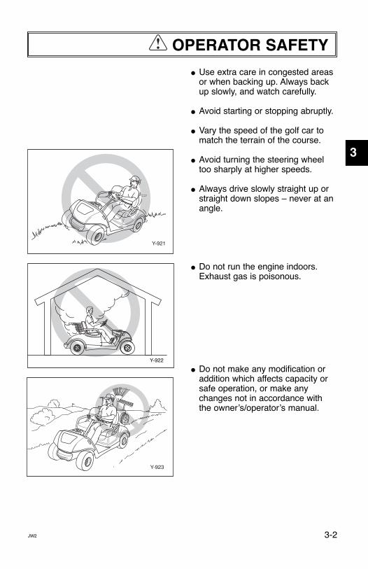
● Use extra care in congested areasor when backing up. Always backup slowly, and watch carefully.
● Avoid starting or stopping abruptly.
● Vary the speed of the golf car tomatch the terrain of the course.
● Avoid turning the steering wheeltoo sharply at higher speeds.
● Always drive slowly straight up orstraight down slopes – never at anangle.
● Do not run the engine indoors.Exhaust gas is poisonous.
● Do not make any modification oraddition which affects capacity orsafe operation, or make anychanges not in accordance withthe ownerʼs/operatorʼs manual.
!
Y-921
Y-922
Y-923
JW2 3-2
1
2
3
4
5
6
7
8
9
10
11
LIT_19626_21_09.qxd:LIT_19626_16_05.qxd 5/21/08 3:51 PM Page 9
SAFETY CONSIDERATIONS!
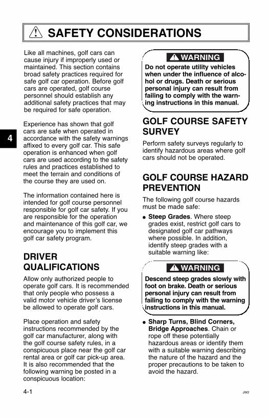
Like all machines, golf cars cancause injury if improperly used ormaintained. This section containsbroad safety practices required forsafe golf car operation. Before golfcars are operated, golf course personnel should establish any additional safety practices that maybe required for safe operation.
Experience has shown that golf cars are safe when operated inaccordance with the safety warningsaffixed to every golf car. This safeoperation is enhanced when golfcars are used according to the safetyrules and practices established tomeet the terrain and conditions ofthe course they are used on.
The information contained here isintended for golf course personnelresponsible for golf car safety. If youare responsible for the operationand maintenance of this golf car, weencourage you to implement thisgolf car safety program.
DRIVER QUALIFICATIONSAllow only authorized people tooperate golf cars. It is recommendedthat only people who possess avalid motor vehicle driverʼs licensebe allowed to operate golf cars.
Place operation and safety instructions recommended by thegolf car manufacturer, along with the golf course safety rules, in aconspicuous place near the golf carrental area or golf car pick-up area.It is also recommended that the following warning be posted in aconspicuous location:
Do not operate utility vehicleswhen under the influence of alco-hol or drugs. Death or seriouspersonal injury can result fromfailing to comply with the warn-ing instructions in this manual.
GOLF COURSE SAFETYSURVEYPerform safety surveys regularly toidentify hazardous areas where golfcars should not be operated.
GOLF COURSE HAZARDPREVENTIONThe following golf course hazardsmust be made safe:
● Steep Grades. Where steepgrades exist, restrict golf cars todesignated golf car pathwayswhere possible. In addition, identify steep grades with a suitable warning like:
Descend steep grades slowly withfoot on brake. Death or seriouspersonal injury can result fromfailing to comply with the warninginstructions in this manual.
● Sharp Turns, Blind Corners,Bridge Approaches. Chain orrope off these potentially hazardous areas or identify themwith a suitable warning describingthe nature of the hazard and theproper precautions to be taken toavoid the hazard.
JW24-1
1
2
3
4
5
6
7
8
9
10
11
LIT_19626_21_09.qxd:LIT_19626_16_05.qxd 5/21/08 3:51 PM Page 10

SAFETY CONSIDERATIONS
● Wet Areas. Wet grass may causea golf car to lose traction and mayaffect stability. Reduce speed inwet areas or during periods ofinclement weather.
● Loose Terrain. Loose terrain maycause a golf car to lose tractionand may affect stability. Repairloose terrain, chain or rope offthese areas, or identify loose terrain with a suitable warning.
● Golf Car and Pedestrian Interference. Reroute golf car traffic or pedestrian traffic in congested areas wherever possibleto prevent accidents. If it is impractical to reroute traffic, erectwarning signs to warn pedestriansof golf car traffic, and to warn golfcar operators to drive slowly, usecaution, and watch for pedestrians.
MAINTENANCE REQUIRED FOR GOLFCAR SAFETYPractice the following to help ensurethe safety of golf car operators:
● Preventative Maintenance. Perform all scheduled maintenance in accordance withmanufacturerʼs recommendationsto provide the golfing patron with asafe, properly operating golf car.
● Personnel. Allow only qualified,trained, and authorized personnelto inspect, adjust, and maintaingolf cars.
● Parts and Materials. Use onlyreplacement parts and materialsrecommended by the manufacturer.
● Ventilation. Properly ventilate allmaintenance and storage areas inaccordance with applicable firecodes and ordinances to avoid firehazards. Ventilation is required toremove flammable vapors andfumes from gasoline powered carstorage areas. Ventilation is alsorequired to remove hydrogen gasfrom the car storage areas duringthe battery charging process.
For electric powered golf cars, theamount of hydrogen gas emittedduring charging depends on anumber of factors, such as thecondition of the batteries, the outputrate of the battery charger, and theamount of time the batteries are oncharge. Because of the highlyvolatile nature of hydrogen gas andits propensity to rise and accumulateat the ceiling in pockets, a minimumof 5 air changes per hour isrecommended. Consult applicablefire and safety codes for the specificventilation levels requirement, aswell as requirements for the use ofexplosion proof electrical apparatus.
!
JW2 4-2
1
2
3
4
5
6
7
8
9
10
11
LIT_19626_21_09.qxd:LIT_19626_16_05.qxd 5/21/08 3:51 PM Page 11
SAFETY CONSIDERATIONS
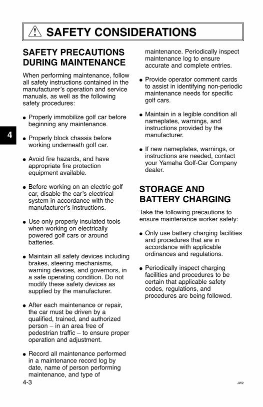
SAFETY PRECAUTIONSDURING MAINTENANCEWhen performing maintenance, followall safety instructions contained in themanufacturerʼs operation and servicemanuals, as well as the followingsafety procedures:
● Properly immobilize golf car beforebeginning any maintenance.
● Properly block chassis before working underneath golf car.
● Avoid fire hazards, and haveappropriate fire protection equipment available.
● Before working on an electric golfcar, disable the carʼs electricalsystem in accordance with themanufacturerʼs instructions.
● Use only properly insulated toolswhen working on electricallypowered golf cars or aroundbatteries.
● Maintain all safety devices includingbrakes, steering mechanisms,warning devices, and governors, ina safe operating condition. Do notmodify these safety devices assupplied by the manufacturer.
● After each maintenance or repair,the car must be driven by aqualified, trained, and authorizedperson – in an area free ofpedestrian traffic – to ensure properoperation and adjustment.
● Record all maintenance performedin a maintenance record log bydate, name of person performingmaintenance, and type of
maintenance. Periodically inspectmaintenance log to ensureaccurate and complete entries.
● Provide operator comment cardsto assist in identifying non-periodicmaintenance needs for specificgolf cars.
● Maintain in a legible condition allnameplates, warnings, andinstructions provided by the manufacturer.
● If new nameplates, warnings, orinstructions are needed, contactyour Yamaha Golf-Car Companydealer.
STORAGE AND BATTERY CHARGINGTake the following precautions toensure maintenance worker safety:
● Only use battery charging facilitiesand procedures that are in accordance with applicable ordinances and regulations.
● Periodically inspect charging facilities and procedures to be certain that applicable safetycodes, regulations, and procedures are being followed.
!
JW24-3
1
2
3
4
5
6
7
8
9
10
11
LIT_19626_21_09.qxd:LIT_19626_16_05.qxd 5/21/08 3:51 PM Page 12
CONTROLS
Y-916a12
3
4
5
16
Y-919a
12
1314Y-918a11 10
9
8
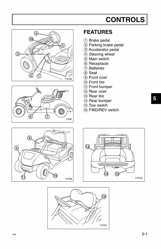
FEATURES1 Brake pedal2 Parking brake pedal3 Accelerator pedal4 Steering wheel5 Main switch6 Receptacle7 Batteries8 Seat9 Front cowla Front tireb Front bumperc Rear cowld Rear tiree Rear bumperf Tow switchg FWD/REV switch
Y-930a
15
Y-93576
JW2 5-1
1
2
3
4
5
6
7
8
9
10
11
LIT_19626_21_09.qxd:LIT_19626_16_05.qxd 5/21/08 3:51 PM Page 13

OFFON
Y-912
REV FWD
OFFON
Y-913
REV FWD
MAIN SWITCHThe main switch controls the following items:
OFFIgnition circuit is switched off.The key can be removed only in thisposition.
ONElectrical circuits are switched on.The golf car can be driven.
JW25-2
CONTROLS
1
2
3
4
5
6
7
8
9
10
11
LIT_19626_21_09.qxd:LIT_19626_16_05.qxd 5/21/08 3:51 PM Page 14

CONTROLS
DRIVE SELECT SWITCHThe drive select switch is used toshift the golf car into forward orreverse. After coming to a completestop, move the lever to the desired position.
Switch Position Car Movement
FWD FORWARD
REV REVERSE
The back-up buzzer will beep whenthe drive select switch is turned to“REV.”
ACCELERATOR PEDALThe accelerator pedal controls thegolf carʼs speed.
Action Car Speed
Depress pedal Increase
Release pedal Decrease
å Accelerator pedal
BRAKE PEDALPress down on the brake pedal tostop the golf car.
∫ Brake pedal
NOTE:
Y-920
BEEP
Y-20A
A
OFFON
Y-904
REV FWD
Y-21a
B
JW2 5-3
1
2
3
4
5
6
7
8
9
10
11
LIT_19626_21_09.qxd:LIT_19626_16_05.qxd 5/21/08 3:51 PM Page 15

CONTROLS
PARKING BRAKEPEDALPress down on the parking brakepedal whenever parking the golf car.
ç Parking brake pedal
Release the parking brake bydepressing the accelerator pedal.
The parking brake will automaticallyrelease when the accelerator pedalis depressed. If the main switch isin the “ON” position, depressingthe accelerator may suddenlycause the golf car to move. Deathor serious personal injury canresult from failing to comply withthe warning instructions in thismanual.
NOTE:Y-22a
C
JW25-4
1
2
3
4
5
6
7
8
9
10
11
LIT_19626_21_09.qxd:LIT_19626_16_05.qxd 5/21/08 3:51 PM Page 16

CONTROLS
TOW SWITCHBefore operating the car, make sure the tow switch is in the “RUN”position.
å Tow switch
Ensure that the “Drive SelectSwitch” is in the “FWD” positionand then move the “TOW Switch”to “TOW” before towing.
Failure to do so may lead to drivesystem damage.
CAUTION
CAUTION / AVERTISSEMENT
TOW
RUN A
Y-666a
JW2 5-5
1
2
3
4
5
6
7
8
9
10
11
LIT_19626_21_09.qxd:LIT_19626_16_05.qxd 5/21/08 3:51 PM Page 17
PRE-OPERATION CHECKS
Y-905
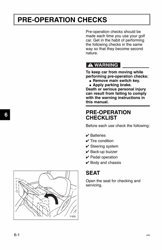
Pre-operation checks should bemade each time you use your golfcar. Get in the habit of performingthe following checks in the sameway so that they become secondnature.
To keep car from moving whileperforming pre-operation checks:
● Remove main switch key. ● Apply parking brake.
Death or serious personal injurycan result from failing to complywith the warning instructions inthis manual.
PRE-OPERATIONCHECKLISTBefore each use check the following:
✔ Batteries✔ Tire condition✔ Steering system✔ Back-up buzzer✔ Pedal operation✔ Body and chassis
SEATOpen the seat for checking and servicing.
JW26-1
1
2
3
4
5
6
7
8
9
10
11
LIT_19626_21_09.qxd:LIT_19626_16_05.qxd 5/21/08 3:51 PM Page 18

PRE-OPERATION CHECKS
BATTERIESCheck that the batteries are heldsecurely in place to prevent themfrom being damaged from vibrationor jarring. Also check that no batterycaps are missing to prevent batteryacid from spilling from the batteries.Check the battery terminals for corrosion.
TIRE CONDITION
Tire Air PressureCheck the tire air pressure beforeoperating the golf car.
Tire pressure:
For JW2: 20 psi(138 kPa, 1.4 kgf/cm2)
Tire Wear LimitCheck the tire surface for damage,cracks or embedded objects. Whentire tread wears down to 0.04 in. (1 mm), replace the tire.
å Wear limit
Y-30
A
Y-31
JW2 6-2
1
2
3
4
5
6
7
8
9
10
11
LIT_19626_21_09.qxd:LIT_19626_16_05.qxd 5/21/08 3:51 PM Page 19

PRE-OPERATION CHECKS
Y-20A
A
Y-932
OFFON
Y-911b
REV FWD
STEERING SYSTEMCheck the steering system forexcessive free play by:
● moving the steering wheel up and down, and back and forth.
● turning the steering wheel slightly to the right and left.
If you feel excessive free play, orhear rattling sounds which may indicate loose steering components,consult a Yamaha dealer.
BACK-UP BUZZERCheck the back-up buzzer by moving the drive select switch to“REV” for reverse. The buzzershould sound.
PEDAL OPERATIONCheck the following pedal controlsfor proper operation. If a pedal doesnot work properly, consult a Yamahadealer.
Accelerator Pedal
Before checking operation of theaccelerator pedal, be sure themain switch is in the “OFF” position. Death or serious person-al injury can result from failing tocomply with the warning instruc-tions in this manual.
Make sure the accelerator pedaloperates smoothly.
å Accelerator pedalJW26-3
1
2
3
4
5
6
7
8
9
10
11
LIT_19626_21_09.qxd:LIT_19626_16_05.qxd 5/21/08 3:51 PM Page 20
PRE-OPERATION CHECKS
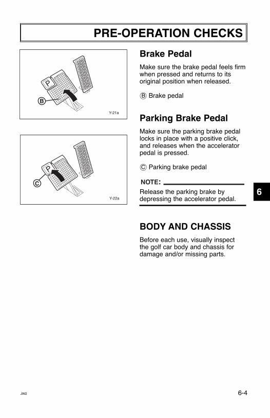
Brake PedalMake sure the brake pedal feels firmwhen pressed and returns to its original position when released.
∫ Brake pedal
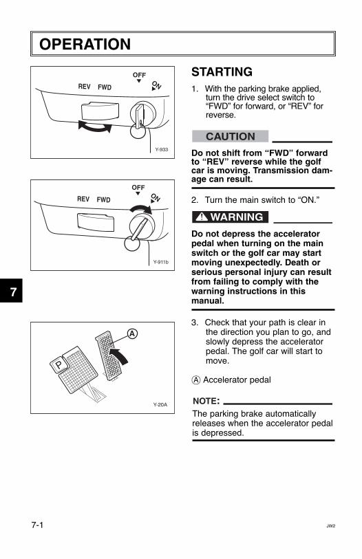
Parking Brake PedalMake sure the parking brake pedallocks in place with a positive click,and releases when the acceleratorpedal is pressed.
ç Parking brake pedal
Release the parking brake bydepressing the accelerator pedal.
BODY AND CHASSISBefore each use, visually inspect the golf car body and chassis fordamage and/or missing parts.
NOTE:
Y-22a
C
Y-21a
B
JW2 6-4
1
2
3
4
5
6
7
8
9
10
11
LIT_19626_21_09.qxd:LIT_19626_16_05.qxd 5/21/08 3:51 PM Page 21
OPERATION
OFFON
Y-911b
REV FWD
REV FWD
OFFON
Y-933
Y-20A
A
STARTING1. With the parking brake applied,
turn the drive select switch to“FWD” for forward, or “REV” forreverse.
Do not shift from “FWD” forwardto “REV” reverse while the golfcar is moving. Transmission dam-age can result.
2. Turn the main switch to “ON.”
Do not depress the acceleratorpedal when turning on the mainswitch or the golf car may startmoving unexpectedly. Death orserious personal injury can resultfrom failing to comply with thewarning instructions in this manual.
3. Check that your path is clear inthe direction you plan to go, andslowly depress the acceleratorpedal. The golf car will start tomove.
å Accelerator pedal
The parking brake automaticallyreleases when the accelerator pedalis depressed.
NOTE:
CAUTION
JW27-1
1
2
3
4
5
6
7
8
9
10
11
LIT_19626_21_09.qxd:LIT_19626_16_05.qxd 5/21/08 3:51 PM Page 22

OPERATION
STOPPINGTo stop the golf car, gradually pressdown on the brake pedal.
å Brake pedal
When the car has come to a stop,apply the parking brake pedal andturn the main switch to “OFF.”
∫ Parking brake pedal
Do not hold the golf car on anincline with the accelerator – usethe brake. Transmission damagecan result.
CAUTIONY-65c
A
B
JW2 7-2
1
2
3
4
5
6
7
8
9
10
11
LIT_19626_21_09.qxd:LIT_19626_16_05.qxd 5/21/08 3:51 PM Page 23

MAINTENANCE
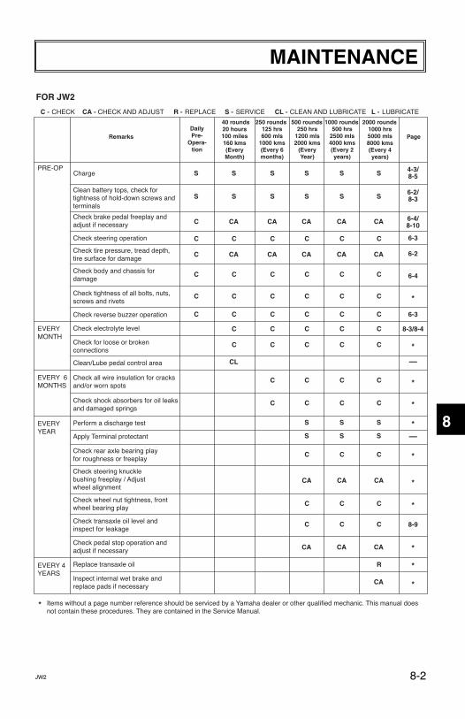
PERIODIC MAINTENANCE CHARTSRegular maintenance is required for the best performance and safe operation ofyour golf car.
Be sure to turn off the main switch and apply the parking brake when you performmaintenance, unless otherwise specified. If the owner is not familiar with servicingthe machine, death or serious personal injury can result. When in doubt the workshould be done by a Yamaha dealer or other qualified mechanic.
JW28-1
1
2
3
4
5
6
7
8
9
10
11
LIT_19626_21_09.qxd:LIT_19626_16_05.qxd 5/21/08 3:51 PM Page 24
MAINTENANCE
DailyPre-
Opera-tion
20 hours100 miles160 kms(EveryMonth)
125 hrs600 mls
1000 kms(Every 6months)
250 hrs1200 mls2000 kms
(EveryYear)
500 hrs2500 mls4000 kms(Every 2years)
1000 hrs5000 mls8000 kms(Every 4years)
PageRemarks
40 rounds 250 rounds 500 rounds 1000 rounds 2000 rounds
ChargePRE-OP
EVERYMONTH
EVERY 6MONTHS
EVERYYEAR
EVERY 4YEARS
4-3/8-5
6-2/8-3
6-4/8-10
*
*
*
*
*
*
*
*
—
—
6-3
6-3
6-2
6-4
8-3/8-4
8-9
*
* Items without a page number reference should be serviced by a Yamaha dealer or other qualified mechanic. This manual doesnot contain these procedures. They are contained in the Service Manual.
C - CHECK CA - CHECK AND ADJUST R - REPLACE S - SERVICE CL - CLEAN AND LUBRICATE L - LUBRICATE
FOR JW2
Clean battery tops, check fortightness of hold-down screws andterminals
Check brake pedal freeplay andadjust if necessary
Check steering operation
Check tire pressure, tread depth,tire surface for damage
Check body and chassis for damage
Check tightness of all bolts, nuts,screws and rivets
Check for loose or brokenconnections
Check all wire insulation for cracksand/or worn spots
Check wheel nut tightness, frontwheel bearing play
Check transaxle oil level andinspect for leakage
Check shock absorbers for oil leaksand damaged springs
Clean/Lube pedal control area
Check reverse buzzer operation
Check electrolyte level
Perform a discharge test
Apply Terminal protectant
Check pedal stop operation and adjust if necessary
Inspect internal wet brake andreplace pads if necessary
Replace transaxle oil
S
S
C
C
C
C
C
C
S
S
CA
CA
CL
C
C
C
C
C
C
S
S
CA
CA
C
C
C
C
C
C
C
C
S
S
S
S
CA
CA
CA
C
C
C
C
C
C
C
C
C
C
S
S
S
S
CA
CA
CA
C
C
C
C
C
C
C
C
C
C
S
S
S
S
CA
CA
CA
CA
C
C
C
C
C
C
C
C
C
C
*
*
Check rear axle bearing playfor roughness or freeplay
C
CA
C
CA
C
CA
R
Check steering knucklebushing freeplay / Adjustwheel alignment
JW2 8-2
1
2
3
4
5
6
7
8
9
10
11
LIT_19626_21_09.qxd:LIT_19626_16_05.qxd 5/21/08 3:51 PM Page 25

MAINTENANCE
Battery Care
Battery electrolyte is poisonousand dangerous, causing severeburns, etc. It contains sulfuric acid.Avoid contact with skin, eyes, orclothing.Antidote:EXTERNAL: Flush with water. INTERNAL: Drink large quantities ofwater or milk. Follow with milk ofmagnesia, beaten egg, or vegetableoil. Call physician immediately.EYES: Flush with water for 15 minutes and get prompt medical attention.Batteries produce explosive gases.Keep sparks, flame, cigarettes, etc.,away.Ventilate when charging or using inenclosed space. Always shield eyeswhen working near batteries.KEEP OUT OF REACH OFCHILDREN.
Four 12-volt deep cycle batteriesprovide power for your electric golfcar and must be properly maintainedand recharged for maximumperformance and service life.
To maintain your batteries:
1. Clean the tops of the batterieswith a solution of baking sodaand water, as necessary, toremove corrosion.
Do not allow cleaning solution toenter battery cells. Serious batterydamage can result.
2. Check the fluid level before andafter charging.
CAUTION
JW28-3
1
2
3
4
5
6
7
8
9
10
11
LIT_19626_21_09.qxd:LIT_19626_16_05.qxd 5/21/08 3:51 PM Page 26

MAINTENANCE
● Before charging: only add distilledwater if fluid is below the top of theplates, and then add just enough tocover plates.
● After charging: open the vent capsand look inside the fill wells. Adddistilled water until the electrolytelevel is 1/8" (3 mm) below the bot-tom of the fill well. A piece of rubbercan be used safely as a dipstick tohelp determine this level. Clean,replace and tighten all vent caps.
Normal tap water containsminerals which are harmful to abattery; therefore, refill only withdistilled water.
3. Using a hydrometer, check thespecific gravity of the battery fluidin each cell against the readingson the chart below. Consult aYamaha dealer if any low readingsare found, or if readings vary morethan one point between cells.
Temperature Satisfactory Uncorrected
˚F ˚C Hydrometer Reading
120 48.9 1.244
110 43.3 1.248
100 37.8 1.252
90 32.2 1.256
80 26.7 1.260
70 21.1 1.264
60 15.6 1.268
50 10.0 1.272
40 4.4 1.276
30 -1.1 1.280
CAUTION
Y-936
POS
NEG
1/8”(3 mm)
Electrolyte 1/8” BelowBottom of Fill Well
Max. Level - discharged battery
Max. Level - charged battery
Fill Well
Electrolyte
Y-937
JW2 8-4
1
2
3
4
5
6
7
8
9
10
11
LIT_19626_21_09.qxd:LIT_19626_16_05.qxd 5/21/08 3:51 PM Page 27

MAINTENANCE
Battery Charging
Read and understand the owner’smanual provided with your golfcar’s battery charger beforecharging batteries. Death or seri-ous personal injury can resultfrom failing to comply with thewarning instructions in this manual.
Explosive hydrogen gas is produced while batteries arebeing charged. Only charge batteries in well ventilated areas(a minimum of five air changesper hour is recommended). Deathor serious personal injury canresult from failing to comply withthe warning instructions in thismanual.
To charge the batteries in your golf car, follow the instructions con-tained in your battery chargerʼsownerʼs manual. The following is asummary of the charging steps. 1. Turn main switch key to “OFF”
position.
Always put the tow switch in theTOW position before charging bat-tery or damage to the electricalsystem may result.
2. Lift up the seat and move the towswitch to the TOW position.
CAUTION
JW28-5
1
2
3
4
5
6
7
8
9
10
11
OFFON
Y-912
REV FWD
LIT_19626_21_09.qxd:LIT_19626_16_05.qxd 5/21/08 3:51 PM Page 28

JW2 8-6
MAINTENANCE
Use only battery chargers that arerated for use with 48-volt YamahaGolf Cars. Serious battery dam-age can result. Thoroughly readand understand the user manual supplied with your 48-volt charger.
3. With the charger properly con-nected and grounded (see charg-erʼs ownerʼs manual), insert theDC output into the golf car recep-tacle.
Do not disconnect the DC outputcord from the battery receptaclewhen the charger is on or an arccould occur that may cause anexplosion. Death or serious per-sonal injury can result from failingto comply with the warninginstructions in this manual.
å Power ON Light (Red)∫ Error Light 1 (Red)ç Error Light 2 (Red)∂ Charging Light (Yellow)fl Charged Light (Green)
4. When the charger is plugged intothe AC power, the Power ONLight illuminates continuously.
5. If Error 1 or Error 2 light is blink-ing, there is a problem with thebatteries or the charger. Contactyour Yamaha Dealer.
6. During normal charging, theCharging Light blinks or continu-ally illuminates.
7. The charger turns off automati-cally when the batteries reach fullcharge.
CAUTION 1
2
3
4
5
6
7
8
9
10
11
POWER ON
ERROR1
ERROR2
CHARGING90%
CHARGED
Y-1559
A
B
C
D
E
Y-669
LIT_19626_21_09.qxd:LIT_19626_16_05.qxd 5/21/08 3:51 PM Page 29
8. After the charger has turned off,disconnect the DC output plugfrom the golf car receptacle bygrasping the plug body andpulling the plug straight out ofthe receptacle.
Battery Installation
When working with batteries, donot put wrenches or other metalobjects across the battery termi-nals. An arc can occur causing anexplosion or fire at the battery.Death or serious personal injurycan result from failing to complywith the warning instructions inthis manual.
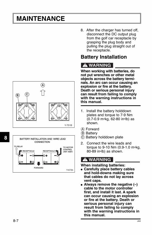
1. Install the battery holddownplates and torque to 7-9 Nm(0.7-0.9 m•kg, 62-80 in•lb) asshown.
å Forward∫ Batteryç Battery holddown plate
2. Connect the wire leads andtorque to 9-10 Nm (0.9-1.0 m•kg,80-89 in•lb) as shown.
When installing batteries:● Carefully place battery cables
and hold-downs making surethat cables do not lay acrossvent caps.
● Always remove the negative (–)cable to the motor controllerfirst, and install it last. A sparkcan occur causing an explosionor fire at the battery. Death orserious personal injury canresult from failing to complywith the warning instructions inthis manual.
PO
S
PO
SN
EG
NE
G
PO
S
PO
SN
EG
NE
G
Y-751B
B C
A
Y-672b
JW28-7
MAINTENANCE
1
2
3
4
5
6
7
8
9
10
11
LIT_19626_21_09.qxd:LIT_19626_16_05.qxd 5/21/08 3:52 PM Page 30
Do not overtighten the batteryholddown nuts. Excessive forcewill damage the battery casing.
Fuse Replacement
Be sure to use the specified fuse.Using a wrong fuse can causeelectrical system damage andcreate a fire hazard. Death or seri-ous personal injury can resultfrom failing to comply with thewarning instructions in this manual.
When replacing a fuse be surethe main switch is turned off toprevent accidental short-circuiting and cause electricalsystem damage.
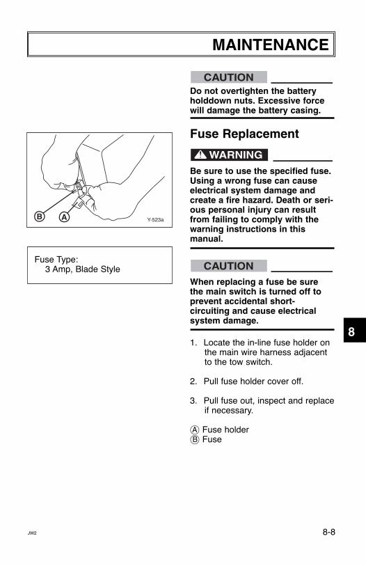
1. Locate the in-line fuse holder onthe main wire harness adjacentto the tow switch.
2. Pull fuse holder cover off.
3. Pull fuse out, inspect and replaceif necessary.
å Fuse holder∫ Fuse
CAUTION
CAUTIONFuse Type:
3 Amp, Blade Style
Y-523aAB
JW2 8-8
MAINTENANCE
1
2
3
4
5
6
7
8
9
10
11
LIT_19626_21_09.qxd:LIT_19626_16_05.qxd 5/21/08 3:52 PM Page 31
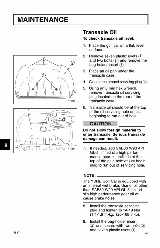
Transaxle OilTo check transaxle oil level:
1. Place the golf car on a flat, levelsurface.
2. Remove seven plastic rivets 1and two bolts 2, and remove thebag holder insert 3.
3. Place an oil pan under thetransaxle case.
4. Clean area around servicing plug 4.
5. Using an 8 mm hex wrench,remove transaxle oil servicingplug located on the rear of thetransaxle case.
6. Transaxle oil should be at the topof the oil servicing hole or justbeginning to run out of hole.
Do not allow foreign material toenter transaxle. Serious transaxledamage can result.
7. If needed, add SAE80 W90 APIGL-5 limited slip high perfor-mance gear oil until it is at thetop of the plug hole or just begin-ning to run out of servicing hole.
The YDRE Golf Car is equipped withan internal wet brake. Use of oil otherthan SAE80 W90 API GL-5 limitedslip high performance gear oil willcause brake noise.
8. Install the transaxle servicingplug and tighten to 14-19 Nm(1.4-1.9 m•kg, 120-168 in•lb).
9. Install the bag holder insert3 and secure with two bolts 2and seven plastic rivets 1.
NOTE:
CAUTION4
Y-1214
Y-1215
1
2
3
JW28-9
MAINTENANCE
1
2
3
4
5
6
7
8
9
10
11
LIT_19626_21_09.qxd:LIT_19626_16_05.qxd 5/21/08 3:52 PM Page 32
8-10
For transaxle oil replacement, con-sult a Yamaha dealer or other quali-fied mechanic.
Before performing wheel or brakemaintenance, verify that the mainswitch is in the “OFF” position.Serious transaxle damage canresult.
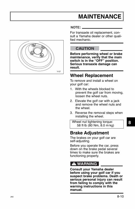
Wheel ReplacementTo remove and install a wheel onyour golf car:
1. With the wheels blocked to prevent the golf car from moving,loosen the wheel nuts.
2. Elevate the golf car with a jackand remove the wheel nuts andthe wheel.
3. Reverse the removal steps wheninstalling the wheel.
Wheel nut tightening torque:58 ft.lb (80 Nm, 8.0 m.kg)
Brake Adjustment The brakes on your golf car are self-adjusting.Before you operate the car, pressdown on the brake pedal severaltimes to make sure the brakes arefunctioning properly.
Consult your Yamaha dealerbefore using your golf car if yoususpect brake problems. Death orserious personal injury can resultfrom failing to comply with thewarning instructions in this manual.
CAUTION
NOTE:
Y-57
JW2
MAINTENANCE
1
2
3
4
5
6
7
8
9
10
11
LIT_19626_21_09.qxd:LIT_19626_16_05.qxd 5/21/08 3:52 PM Page 33
Brake Pedal Free PlayAdjustment
Before adjusting brake pedal freeplay, pump the brake pedal severaltimes to self-adjust the brakes.
To adjust the brake pedal free play:
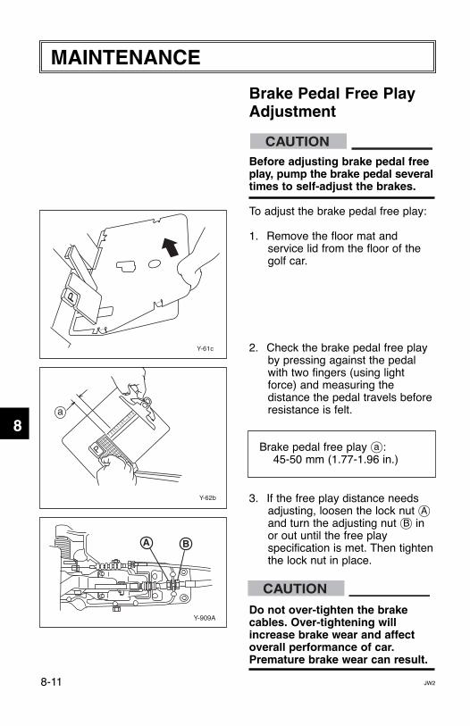
1. Remove the floor mat and service lid from the floor of thegolf car.
2. Check the brake pedal free playby pressing against the pedalwith two fingers (using lightforce) and measuring the distance the pedal travels beforeresistance is felt.
Brake pedal free play Å:45-50 mm (1.77-1.96 in.)
3. If the free play distance needsadjusting, loosen the lock nut åand turn the adjusting nut ∫ in or out until the free play specification is met. Then tightenthe lock nut in place.
Do not over-tighten the brakecables. Over-tightening willincrease brake wear and affectoverall performance of car.Premature brake wear can result.
CAUTION
Y-61c
Y-909A
A B
Y-62b
7
1817
1615
1413
1211
109
8
a
JW28-11
MAINTENANCE
1
2
3
4
5
6
7
8
9
10
11CAUTION
LIT_19626_21_09.qxd:LIT_19626_16_05.qxd 5/21/08 3:52 PM Page 34

2. Have the batteries rechargedevery 60-90 days to keep themfully charged. The batteries mustbe kept fully charged to avoid damage.
Do not allow cleaning solution toenter battery cells. Serious bat-tery damage can result.
3. Clean the top of the batterieswith a solution of baking sodaand water, as necessary, toremove corrosion.
CAUTION
Perform the following preparationswhen storing your golf car forextended periods of time:
Turn main switch key to “OFF”position, remove key, and store keyin a safe place.
CHASSIS PREPARATION1. Verify the tire pressure is set to
20 psi (138 kPa, 1.4 kgf/cm2).
2. Clean exterior of the golf car andapply a rust inhibitor.
3. Cover the golf car with a breathable cover and store it in adry, well-ventilated area.
BATTERY PREPARATION1. Remove the batteries from the
golf car and store them in a cool,dry place that stays between 32˚F (0˚C) and 90˚F (30˚C).
NOTE:
JW2 9-1
STORAGE
1
2
3
4
5
6
7
8
9
10
11
LIT_19626_21_09.qxd:LIT_19626_16_05.qxd 5/21/08 3:52 PM Page 35

GENERAL SPECIFICATIONS
Items YDREDimensions:
Overall length 93.4 in. (2395 mm)Overall width 47.2 in. (1200 mm)Overall height (steering height) 46.9 in. (1190 mm)Height of floor 12.2 in. (310 mm)Wheelbase 64.6 in. (1640 mm)Tread:Front 34.3 in. (870 mm)Rear 38.6 in. (980 mm)
Min. ground clearance 4.3 in. (110 mm)
Weight:
Dry weight (without battery) 536 lb (243 kg)
Vibration Level:
Vibration on seat (EN1032,
ISO5008) (for Europe Will not exceed 0.5 m/s2
Vibration on steering wheel
(EN1032, ISO5008) (for Europe) Will not exceed 2.5 m/s2
Performance:
Factory speed setting 12 mph (19 km/h)
Maximum speed 15 mph (24 km/h)
Turning radius 9.2 ft (2.8 m)
Seating capacity 2 persons per seat
TRANSMISSION
Items YDRE
Differential/reduction gear:Differential type Bevel gearLubricant/capacity SAE80 W90 API GL-5 limited slip
high performance gear oil/1.43 US quarts
(1350 mL, 1350 cc)
JW210-1
SPECIFICATIONS
1
2
3
4
5
6
7
8
9
10
11
LIT_19626_21_09.qxd:LIT_19626_16_05.qxd 5/21/08 3:52 PM Page 36
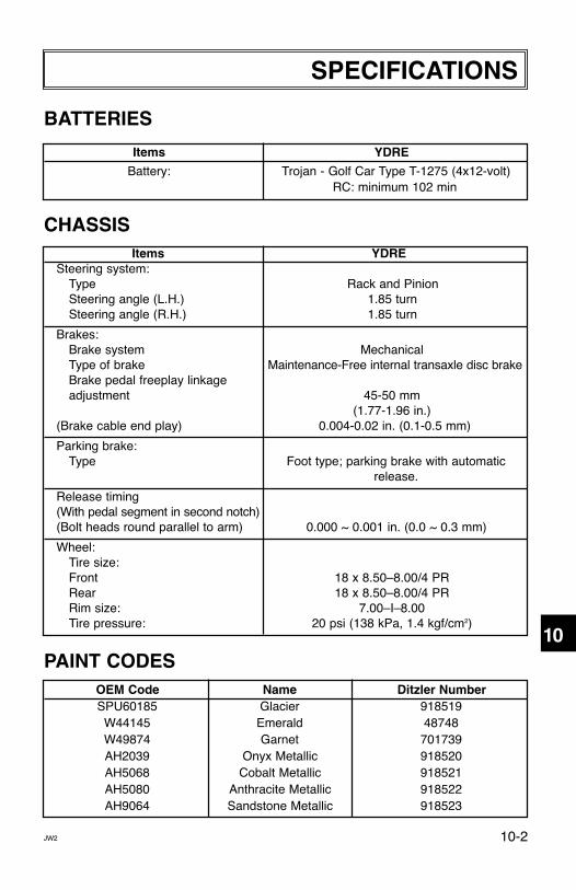
BATTERIES
Items YDRE
Battery: Trojan - Golf Car Type T-1275 (4x12-volt)RC: minimum 102 min
CHASSISItems YDRE
Steering system:Type Rack and PinionSteering angle (L.H.) 1.85 turnSteering angle (R.H.) 1.85 turn
Brakes:Brake system MechanicalType of brake Maintenance-Free internal transaxle disc brakeBrake pedal freeplay linkageadjustment 45-50 mm
(1.77-1.96 in.)(Brake cable end play) 0.004-0.02 in. (0.1-0.5 mm)
Parking brake:Type Foot type; parking brake with automatic
release.
Release timing(With pedal segment in second notch)(Bolt heads round parallel to arm) 0.000 ~ 0.001 in. (0.0 ~ 0.3 mm)
Wheel:Tire size:Front 18 x 8.50–8.00/4 PRRear 18 x 8.50–8.00/4 PRRim size: 7.00–I–8.00Tire pressure: 20 psi (138 kPa, 1.4 kgf/cm2)
PAINT CODESOEM Code Name Ditzler NumberSPU60185 Glacier 918519W44145 Emerald 48748W49874 Garnet 701739AH2039 Onyx Metallic 918520AH5068 Cobalt Metallic 918521AH5080 Anthracite Metallic 918522AH9064 Sandstone Metallic 918523
JW2
SPECIFICATIONS
1
2
3
4
5
6
7
8
9
10
11
10-2
LIT_19626_21_09.qxd:LIT_19626_16_05.qxd 5/21/08 3:52 PM Page 37
Y-94
0b
CO
LOR
CO
DE
B...
......
......
.....B
lack
L...
......
......
......
.Blu
eG
......
......
......
.Gre
enY
......
......
......
.Yel
low
R...
......
......
......
.Red
P...
......
......
......
.Pin
kB
r....
......
......
..Bro
wn
W...
......
......
....W
hite
B/R
......
...B
lack
/Red
Y/B
.....Y
ello
w/B
lack
R/Y
......
.Red
/Yel
low
R/W
......
..Red
/Whi
te
L
BL
B
LO
B
(NO
TE 2
)
RW
RY
RY
RW
OF
F
ON
RW
BO
L
RY
TH
RO
TT
LE
PO
SIT
ION
SE
NS
OR
B
BB
W RW
W
YR
Y
RY
Y
W
BR
G
RY
RW
B
GATE DRIVER CIRCUIT
PWM OUTPUT
RB
PB
PB
PB
BU
ZZ
ER
RW
Br
RW
Br
WRY Y
BA
TT
ER
Y(4
x12v
)
RE
CE
PTA
CLE
CO
NT
RO
LLE
R
3 5 6 7
13
2
Gy
Gy
CH
AR
GE
R D
ATA
RE
CE
IVE
1211
84
109
2426
25
RE
VF
WD
RY Y W
(N
OT
E 1
)D
IRE
CT
ION
AL
SW
.
TACH
A1F1
(A2)
(A1)
A2
F2
D.C
. MO
TO
R
(F2)
(F1)
(P)
(N)
MO
SF
ET
BO
AR
DA
SS
Y.
1
GA
UG
E P
IN-O
UT
1 2 3 4
BA
TT
ER
Y +
BA
TT
ER
Y -
NO
T U
SE
DK
EY
SW
.
RY
RW
TO
W/
ST
OR
AG
E S
W.
B
OP
TIO
NA
LB
AT
TE
RY
GA
UG
E
CONT
ROL B
OARD
AS
SYR
R
RE
LAY
FUSE (3 AMP)
CO
NN
EC
TO
R S
UP
PLI
ED
ON
JW
2-H
2590
-10
WIR
E H
AR
NE
SS
ON
LY
MA
IN S
W.
(NO
TE 1
)
OFF
ON
R RY
RWR
WB
r
OFF
ON
Br RW
(N
OT
E 1
)A
CC
EL.
SW
.
RY
RB
RW
RB
RW
RY
RY
RY
RY
OO
GB
RR G B
R G B
RYR
22 21 20 19
BW
I.R.
TRAN
SCEI
VER
WR
BB
WRB
W
BW R
OP
TIO
NA
L
B W
1
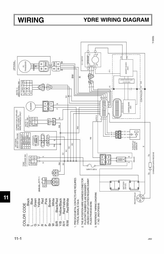
1. P
RE
CIO
US
ME
TAL
CO
NTA
CTS
AR
E R
EQ
UIR
ED
.
TYP
ICA
L S
IGN
AL
IS 1
0mA
.
2. T
HE
26
PO
SIT
ION
WIR
E H
AR
NE
SS
CO
NE
CTO
R
PLU
G P
AR
T N
UM
BE
R IS
JA
E M
X23
A26
SF1
.
UN
US
ED
CIR
CU
IT C
AV
ITIE
S R
EQ
UIR
E D
UM
MY
P
LUG
S P
/N M
120-
5578
0.
3. R
EFE
RE
NC
E "W
IRIN
G D
IAG
RA
M,
1"
, NO
. JW
2-O
F003
-00.
JW211-1
WIRING YDRE WIRING DIAGRAM
1
2
3
4
5
6
7
8
9
10
11
LIT_19626_21_09.qxd:LIT_19626_16_05.qxd 5/21/08 3:52 PM Page 38

48 VOLT GOLF CAR YDRE
LIT-19626-21-09 JW2-F8199-11YAMAHA GOLF-CAR
COMPANY1000 HWY 34 EastNewnan, GA 30265
770-254-4000
Printed in U.S.A2008-KCC
LIT_19626_21_09 cover.qxd:LIT_19626_11_07 cover.qxd 5/12/08 9:31 AM Page 1