4.5 slope protection - kentucky transportation cabinet resources/3-slope...• the maximum slope...
TRANSCRIPT
Kentucky Construction Site BMP Planning and Technical Specifications Manual 75
4.5 Slope Protection
General Information
Relatively flat areas—those with slopes of 2 percent or less—can be treated to a large extent through controlled clearing and grading, mulch, and temporary or permanent seed. Slopes greater than that, however, require more attention to sheet runoff volume and the management of areas where flows converge and are transported to downstream receiving waters. Sediment barriers, rolled erosion control products, and greater attention to downslope drainage are usually needed on slopes, especially those that are steep and long.
This section addresses erosion protection and sediment control approaches specifically for slopes. In general slopes that are long (50 feet or more), steep (5 percent plus), and composed of highly erodible (silty) soils require more protection that shorter, flatter slopes of less erodible soil. Slope protection approaches discussed below include erosion control blankets and turf reinforcement mats, which can also be used for ditch protection, surface roughening, slope drains, gabion structures, and cellular mats.
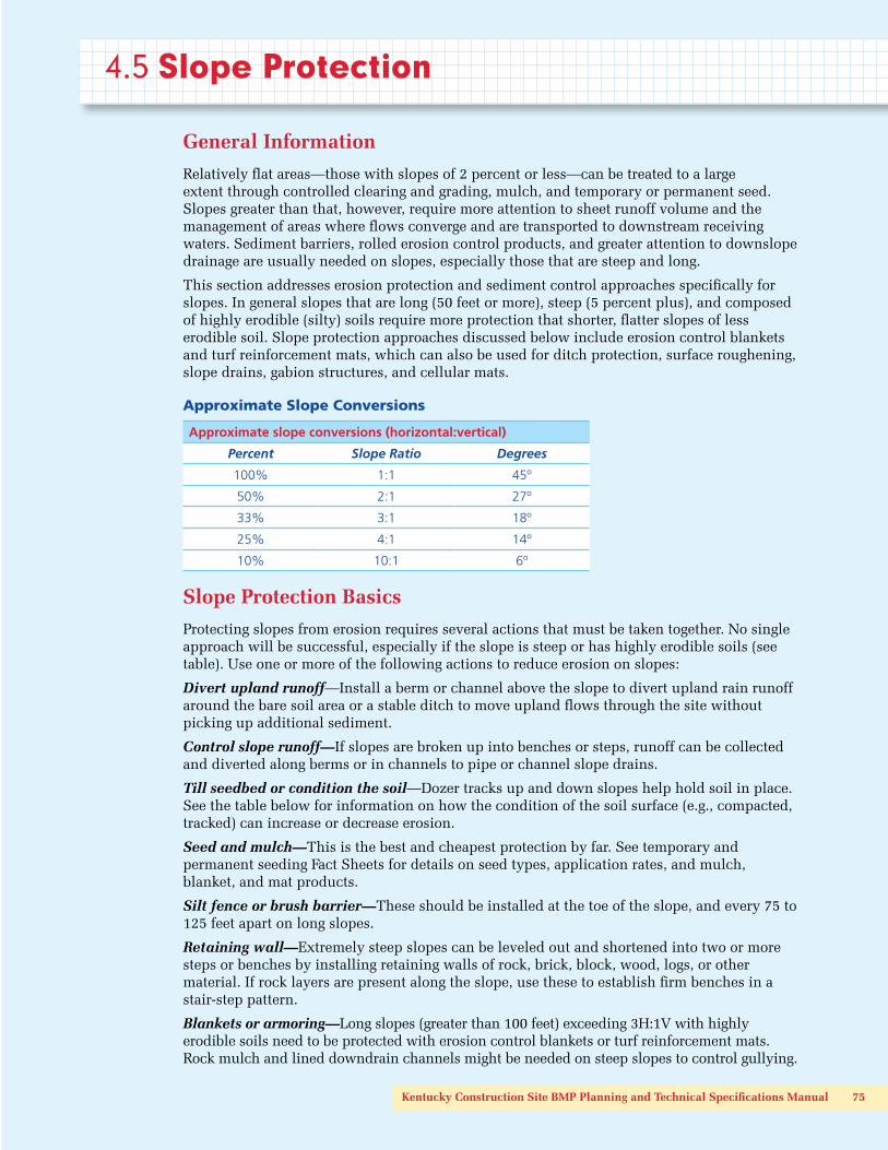
Approximate Slope Conversions
Approximate slope conversions (horizontal:vertical)
Percent Slope Ratio Degrees
100% 1:1 45º
50% 2:1 27º
33% 3:1 18º
25% 4:1 14º
10% 10:1 6º
Slope Protection Basics
Protecting slopes from erosion requires several actions that must be taken together. No single approach will be successful, especially if the slope is steep or has highly erodible soils (see table). Use one or more of the following actions to reduce erosion on slopes:
Divert upland runoff—Install a berm or channel above the slope to divert upland rain runoff around the bare soil area or a stable ditch to move upland flows through the site without picking up additional sediment.
Control slope runoff—If slopes are broken up into benches or steps, runoff can be collected and diverted along berms or in channels to pipe or channel slope drains.
Till seedbed or condition the soil—Dozer tracks up and down slopes help hold soil in place. See the table below for information on how the condition of the soil surface (e.g., compacted, tracked) can increase or decrease erosion.
Seed and mulch—This is the best and cheapest protection by far. See temporary and permanent seeding Fact Sheets for details on seed types, application rates, and mulch, blanket, and mat products.
Silt fence or brush barrier—These should be installed at the toe of the slope, and every 75 to 125 feet apart on long slopes.
Retaining wall—Extremely steep slopes can be leveled out and shortened into two or more steps or benches by installing retaining walls of rock, brick, block, wood, logs, or other material. If rock layers are present along the slope, use these to establish firm benches in a stair-step pattern.
Blankets or armoring—Long slopes (greater than 100 feet) exceeding 3H:1V with highly erodible soils need to be protected with erosion control blankets or turf reinforcement mats. Rock mulch and lined downdrain channels might be needed on steep slopes to control gullying.

76 Technical Specifications for BMPs
Soil Conditions vs. Erosion
Soil Conditions vs. Erosion
If soil is: Erosion will be:
Compacted and smooth 30 percent more
Tracks across slopes 20 percent more
Tracks up & down slopes 10 percent less
Rough and irregular 10 percent less
Rough & loose to 12" deep 20 percent less
Slope Angle and Soil Type vs. Erodibility
Slope angle Erodibility Soil type
50%40%30%20%15%10%5%
< 5%
Very high
Very Low
SiltSilty sand
Clayey sandOrganic soil
ClaysSilty gravel
SandGravel
The value of seed on a slope: the left (seeded) section shows almost no erosion; right side rills are quickly becoming gullies. Seed and mulch slopes as soon as final grade is established for best results. Bare areas must be seeded or mulched within 14 days if no work is planned during the next week.
Kentucky Construction Site BMP Planning and Technical Specifications Manual 77
4.5 Slope Protection
4.5.1 Silt Fence
DefinitionA silt fence is a temporary sediment barrier consisting of filter fabric entrenched into the soil and attached to supporting posts. Silt fences are downhill from bare soil areas and are installed with a trencher or by a slicing machine to prevent against common silt fence failures.
Purpose Silt fences are common sediment control devices. Silt fencing should be installed where sediment-laden water can pond, thus allowing the sediment to fall out of suspension and separate from the runoff. Runoff will also bleed through the silt fence fabric, providing physical filtering for larger sediment particles. Reasons for the high failure rate of improperly designed (located) and installed silt fence include
• Improper placement on the site
• Allowing excessive drainage area to the silt fence structure
• Shallow trenches with little or no soil compaction
• Inadequate attachment to posts
• Failure to maintain the silt fence after installation
• Installing silt fence along property boundaries, producing concentrated runoff
Design Criteria Silt fencing must be installed only where water can pond. Specify silt fencing downgradient from bare soil areas, installed on the contour if possible, with the ends turned up to prevent bypassing. Provide adequate setbacks from slope toe for routine maintenance and access. Silt fencing can be used where
• Non-concentrated sheet flow will occur
• Protection of adjacent property or nearby surface waters is required
• The size of the drainage area is no more than 1/4 acre per 100 linear feet of silt fence
• The maximum flow path length above the barrier is 100 feet for slopes less than 2 percent, and 50 feet for slopes up to 10 percent
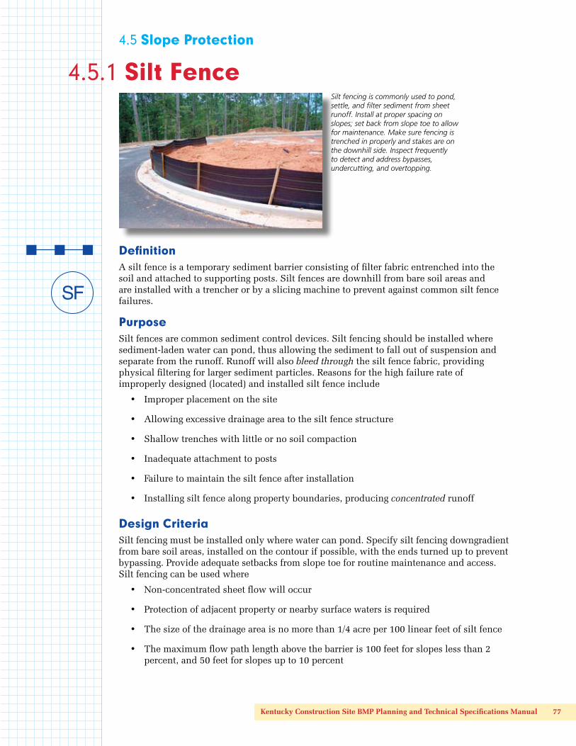
Silt fencing is commonly used to pond, settle, and filter sediment from sheet runoff. Install at proper spacing on slopes; set back from slope toe to allow for maintenance. Make sure fencing is trenched in properly and stakes are on the downhill side. Inspect frequently to detect and address bypasses, undercutting, and overtopping.

78 Technical Specifications for BMPs
• The maximum slope gradient above the barrier is 2H:1V
• Silt fencing can be used in flat, short swales (i.e., slope is less than 2 percent; length is less than 200 feet) that drain less than 2 acres, if silt fencing is spaced every 50 feet.
• Reinforced silt fence must be required when the contributing slope is longer than 100 feet and greater than 3 percent and the design life of the silt fence is greater than 6 months.
Silt Fence Spacing on Long Slopes
Land Slope Max. Slope Distance
3% – 5% 100 ft.
5% – 10% 75 ft.
10% – 20% 50 ft.
20% – 50% 25 ft.
Silt fencing should not be used
• Around the perimeter of the construction site, unless J-hooks are used. Long continuous runs of silt fence will divert and concentrate sediment-laden runoff and almost certainly result in failure. A good general rule is to drain no more than 1/3 acre of disturbed area into each discrete J-hook;
• In ditches, channels, or streams. Silt fences cannot handle the volumes generated by concentrated channel flows. When installed across a concentrated flow path, undercutting or end cutting of the fence often occurs, or the fence is pushed over by the force of the flow.
Construction SpecificationsSilt fences have a useful life of one season. Their principal mode of action is to slow and pond the water and allow soil particles to settle with some minor filtration through the fabric. Silt fences are not designed to withstand high heads of water, and therefore should be located where only shallow pools (i.e., 1.5 feet or less) can form. Their use is limited to situations in which sheet or overland flows are expected.
• Dig a trench on the contour at least 6 inches wide and 6 inches deep below the area to be treated, taking care to install J-hooks where flows will travel along the silt fence. Turn fence ends uphill to trap potential bypasses as needed.
• If posts are already attached to fabric, position the fencing so the posts are installed on the downhill side of the fabric. Drive posts to a depth of 1 foot below the bottom of the trench, against downslope trench wall for extra support. Posts for all silt fencing are spaced 6 feet apart.
• Push fabric into the trench, and spread fabric along trench bottom and sides; backfill the trench and compact the soil. A preferred installation technique in deep, easily-worked soils with minimal rock content involves static slicing of the fence into the ground with a chisel-plow implement such as the Tommy Silt Fence Machine or equivalent. The filter fabric is wire-tied directly to the posts with three diagonal ties.
• The height of a silt fence must be 18 inches minimum and 30 inches maximum. Sediment storage height and ponding height must not exceed 18 inches.
• Silt fences placed at the toe of a slope must be set at least 6 feet back from the toe to increase ponding volume and provide room for maintenance.

Kentucky Construction Site BMP Planning and Technical Specifications Manual 79
Inspection and MaintenanceAll sediment barriers should be placed downgradient from bare areas to be treated. The ends of the barrier should be turned uphill or otherwise configured to prevent end-around bypasses.
• Inspect fence for proper installation and compaction by pulling up on the fence while kicking the toe of the fabric. If the fence comes out of the ground, do not accept the installation.
• If there are long, linear runs of silt fence without J-hooks, do not accept the installation.
• Silt fences and filter barriers must be inspected weekly and after each storm of greater than one-half inch. Any required repairs must be made immediately.
• Sediment should be removed when it reaches 1/3 height of the fence or 18 inches maximum.
• The removed sediment must be spread and vegetated or otherwise stabilized so that it does not result in muddy runoff to nearby ditches or surface waters.
• Silt fences must be removed when they have served their useful purpose, but not before the upslope area has been permanently stabilized (e.g., vegetated) and any sediment stored behind the silt fence has been removed. Silt fences and other temporary controls must be removed before project close-out.
Make sure silt fence fabric is trenched in and is upslope of stakes. Leave room between the fencing and the upgradient slope for removing accumulated sediment.
Install silt fencing on the contour, with the ends turned uphill to trap muddy runoff and prevent bypasses. Remove silt fences when grass is established.
Do not use silt fencing in areas of concentrated flows.
For best results, triple-seed ditches and line with erosion
control blankets.
80 Technical Specifications for BMPs
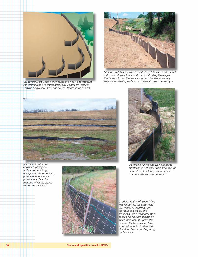
Silt fence is functioning well, but needs maintenance. Set fences back from the toe of the slope, to allow room for sediment to accumulate and maintenance.
Use several short lengths of silt fence and J-hooks to intercept converging runoff in critical areas, such as property corners. This can help relieve stress and prevent failure at the corners.
Silt fence installed backwards—note that stakes are on the uphill, rather than downhill, side of the fabric. Ponding flows against this fence will push the fabric away from the stakes, causing failure and releasing sediment to the small stream on the right.
Use multiple silt fences at proper spacing (see table) to protect long, unvegetated slopes. Fences provide only temporary protection and can be removed when the area is seeded and mulched.
Good installation of “super” (i.e., wire reinforced) silt fence. Note that wire is installed between the fabric and stakes, and provides a web of support as the ponded flow pushes against the fabric. Also, note the grass strip between the bare area and the fence, which helps to slow and filter flows before ponding along the fence line.

Kentucky Construction Site BMP Planning and Technical Specifications Manual 81

82 Technical Specifications for BMPs

Kentucky Construction Site BMP Planning and Technical Specifications Manual 83

84 Technical Specifications for BMPs
Kentucky Construction Site BMP Planning and Technical Specifications Manual 85
86 Technical Specifications for BMPs
4.5 Slope Protection
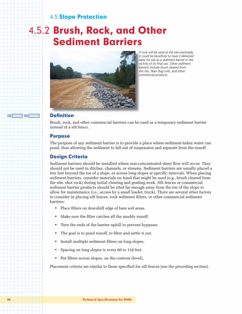
4.5.2 Brush, Rock, and Other Sediment Barriers
DefinitionBrush, rock, and other commercial barriers can be used as a temporary sediment barrier instead of a silt fence.
Purpose The purpose of any sediment barrier is to provide a place where sediment-laden water can pond, thus allowing the sediment to fall out of suspension and separate from the runoff.
Design Criteria Sediment barriers should be installed where non-concentrated sheet flow will occur. They should not be used in ditches, channels, or streams. Sediment barriers are usually placed a few feet beyond the toe of a slope, or across long slopes at specific intervals. When placing sediment barriers, consider materials on hand that might be used (e.g., brush cleared from the site, shot rock) during initial clearing and grading work. Silt fences or commercial sediment barrier products should be sited far enough away from the toe of the slope to allow for maintenance (i.e., access by a small loader, truck). There are several other factors to consider in placing silt fences, rock sediment filters, or other commercial sediment barriers:
• Place filters on downhill edge of bare soil areas.
• Make sure the filter catches all the muddy runoff.
• Turn the ends of the barrier uphill to prevent bypasses
• The goal is to pond runoff, to filter and settle it out.
• Install multiple sediment filters on long slopes.
• Spacing on long slopes is every 60 to 110 feet.
• Put filters across slopes, on the contour (level).
Placement criteria are similar to those specified for silt fences (see the preceding section).
If rock will be used at the site eventually, it could be beneficial to have it delivered early for use as a sediment barrier in the vicinity of its final use. Other sediment barriers include brush cleared from the site, fiber (log) rolls, and other commercial products.

Kentucky Construction Site BMP Planning and Technical Specifications Manual 87
Construction SpecificationsBrush cleared from the site can make an excellent sediment filter if it is properly placed and built up well. Brush barriers are installed on the contour and are 2–5 feet high and 4–10 feet wide at the base. They should be walked down with a loader or dozer to compress the material.
A rock berm can also provide an effective and low-maintenance sediment barrier. Rock berms placed in concentrated flow areas function as sediment traps (for more information on that type of application, see Section 4.7.1). Longer rock berms constructed as sheet runoff sediment barriers should be 18" to 30" in height and consist of stone 2–6 inches in diameter.
Fiber rolls and other commercial products made from coconut fiber, plastic, wood shavings, compost, or other material can also be used as sediment barriers on slopes flatter than 10:1. Follow manufacturers’ installation instructions and ensure that sediment filter spacing on slopes is correct.
For information on locating and installing rock or commercial barriers, see construction specifications for silt fences in the preceding section.
Inspection and MaintenanceSediment barriers should be inspected weekly and after each rainfall of greater than one-half inch. Look for signs of bypassing along the sides, undercutting below the barrier, overtopping, or blowout. Make required repairs immediately. For recurring blowouts, consider pulling some upland muddy flow away and trapping it before it can reach the blowout area. Use a J-hook or other strategically placed barrier.
Remove sediment when it reaches 1/3 height of the fence or 9 inches maximum. Spread the removed sediment and vegetate or otherwise stabilize it.
Remove sediment barriers when they have served their useful purpose but not before the upslope area has been permanently stabilized (i.e., vegetated or otherwise covered) and any sediment stored behind the barrier has been removed.
Fiber rolls provide excellent protection for residential lots. They can be stepped over and driven over, and are preferable to silt fencing in tight areas.
Brush cleared from the site used as a temporary downslope sediment barrier. Make sure barrier intercepts and ponds up muddy runoff. Remove when grass is established.
Super (wire reinforced) silt fence in the foreground, supplemented by rock sediment barrier (background). Use rock or other sediment barriers when appropriate.

88 Technical Specifications for BMPs
4.5 Slope Protection
4.5.3 Erosion Control Blankets and Turf Reinforcement Mats
DefinitionTemporary erosion control blankets (ECBs) and permanent turf reinforcement mats (TRMs), known generally as rolled erosion control products, are single or multiple layer sheets composed of natural or synthetic material that is woven, sewn, bonded, or otherwise manufactured for placement on bare soil slopes or flow channels. They have been described as a temporary, degradable products composed of processed natural or polymer fibers mechanically, structurally, or chemically bound together to form a continuous matrix to provide erosion control and facilitate vegetation establishment.
PurposeECBs are used to temporarily stabilize and protect disturbed soil from raindrop impact and surface erosion, to increase infiltration, decrease compaction and soil crusting, and to conserve soil moisture. Mulching with ECBs will increase the germination rates for grasses and legumes and promote vegetation establishment. ECBs also protect seeds from predators, reduce desiccation and evaporation by insulating the soil and seed environment.
Some types of ECBs and turf reinforcement mats are specifically designed to stabilize channelized flow areas. These blankets and mats can aid the establishment of vegetation in waterways and increase the maximum permissible velocity of the given channel by reinforcing the soil and vegetation to resist the forces of erosion during runoff events. Stems, roots and rhizomes of the vegetation become intertwined with the mat, reinforcing the vegetation and anchoring the mat.
Design CriteriaAll final slopes 2H:1V or steeper should be protected with an ECB. ECBs are constructed of various degradable organic / synthetic fibers that are woven, glued or structurally bound with nettings or meshes. The most widely used ECBs are made from straw, wood excelsior, coconut, polypropylene or a combination thereof stitched or glued together or into or between biaxially oriented process nettings or woven natural fiber nettings. They are useful on sites requiring greater, more durable or longer-lasting erosion protection. Applications include gradual to steep slopes, low to moderate flow channels and low-impact shore linings. Because these degradable materials are designed to provide temporary erosion protection, they generally are limited to areas where natural, unreinforced vegetation alone will provide long-term soil stabilization.
Erosion control blankets provide excellent protection for seedbeds, especially on slopes and in areas of high winds. Blankets can be used to stabilize ditches with flatter slopes. For steeper ditches, use turf reinforcement mats.

Kentucky Construction Site BMP Planning and Technical Specifications Manual 89
The functional longevity of ECBs can be varied to accommodate the site-specific requirements. Some ECBs are designed to last for less than 3 months for use in high-maintenance areas that will be mowed soon after turf establishment, while others are made to provide longer-lasting protection in applications requiring erosion control/mulch for up to 3 years.
TRMs consist of various UV-stabilized, synthetics fibers and filaments processed into permanent, high-strength, 3-D matrices. Common examples include cuspated polyethylene meshes heat-bonded together, extruded monofilaments of nylon or PVC heat-bonded at their intersections, and crimped polyolefin fibers and other materials mechanically stitched between high-strength nettings. TRMs are designed for permanent and critical hydraulic applications such as drainage channels, where design discharges exert velocities and shear stresses that exceed the limits of mature, natural vegetation. Though some TRMs also contain degradable components to supplement their permanent structures, all TRMs by definition have a permanent three dimensional structure with high-tensile strength that functions as a matrix for entangling plant roots, stems and soils.
Together, the TRM and vegetation form a continuous composite—a unified, living mat. This synergism increases root systems’ lateral strength, reducing plant dislodgement under high-velocity, high-shear stress flows. The TRM’s permanent structure also functions to consolidate and protect the soils in which the plants are anchored, preventing soil from being stripped out of the vegetative cover and the resulting weakening of the root support. TRMs are often used in situations where the green alternative is preferred to hard armor.
Select the ECB or TRM according to slope steepness and length and expected sheer stress if application is to a flow channel or ditch. If the area will be mowed eventually, consider the specified breakdown time for ECB plastic netting. TRM areas should not be mowed until vegetation is well established, and then as little (or as high) as possible. The table at the end of this section provides guidance on the application of various blankets and mats. An ECB or mat should be used in all drainage channels with slopes of 2 percent or more, and in the following conditions:
• Slopes and disturbed soils where mulch must be anchored and other methods such as crimping or tackifying are not feasible nor adequate
• Steep, long slopes, generally steeper than 3H:1V and longer than 50 feet
• Slopes where erosion hazards are high
• Critical slopes adjacent to sensitive areas such as streams and wetlands
• Disturbed soil areas where planting is likely to be slow in providing adequate protective cover
Take care to choose the type of blanket or matting that is appropriate for the specific needs of a project. There are many soil stabilization products available today, and it is very difficult to cover all the advantages, disadvantages and specifications of all the manufactured blankets and mats. Therefore, as with many erosion control type products, there is no substitute for a thorough understanding of manufacturer’s instructions and recommendations and a site visit by a designer or plan reviewer to verify a product’s appropriateness.
Construction SpecificationsECBs and TRMs are designed to cover germinating seed and provide a protective matrix that helps anchor seed to the underlying soil. (Note: a few TRMs have seed embedded in the mat.) This requires complete, uniform contact with the soil, solid stapling, and attention to topslope anchoring, overlaps, and other installation details, as noted below.
90 Technical Specifications for BMPs
Site Preparation
Proper site preparation is essential to ensure complete contact of the protection matting with the soil.
• Grade and shape area of installation
• Remove all rocks, roots, clods, vegetative, or other obstructions so that the installed blankets or mats will have direct contact with the soil
• Prepare seedbed by loosening 2–3 inches of topsoil above final grade
• Incorporate amendments, such as lime and fertilizer, into soil according to soil test and the seeding plan
Seeding
Seed the area before installing blanket for erosion control and revegetation. Seeding after mat installation is sometimes specified for turf reinforcement application—check the manufacturer’s instructions. When seeding before blanket installation, reseed all check slots and other areas disturbed during installation.
Where soil filling is specified for certain TRMs, seed the matting and the entire disturbed area after installation and before filling the mat with soil. Follow the manufacturer’s instructions to ensure proper installation.
Anchoring
U-shaped wire staples, metal geotextile stake pins, or triangular wooden stakes can be used to anchor ECBs and TRMs to the ground surface. Wire staples should be a minimum of 11 gauge. Metal stake pins should be 3/16 inch diameter steel with a 1.5 inch steel washer at the head of the pin. Wire staples and metal stakes should be driven flush to the soil surface. All anchors should be 6–8 inches long and have sufficient ground penetration to resist pullout. Longer anchors might be required for loose soils. Use biodegradable composite or wooden stakes where dislodged metal staples or stakes might cause extreme hazards, such as near airport runways or areas where future mowing might cause risk.
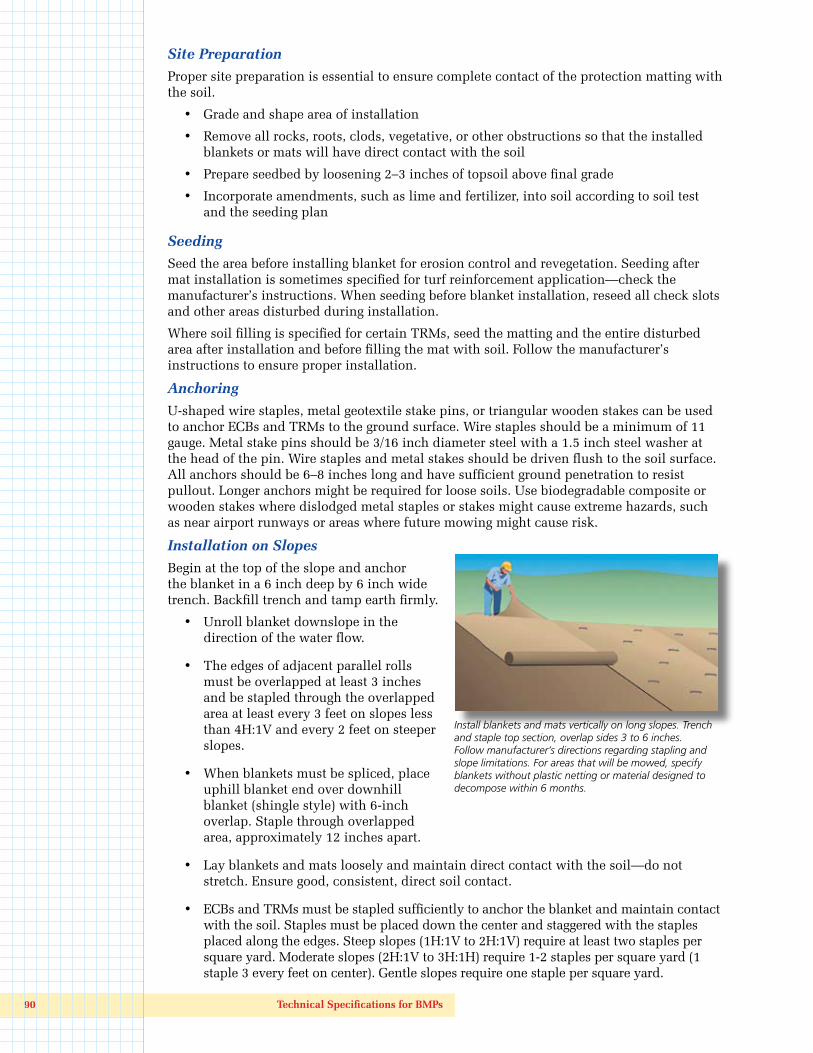
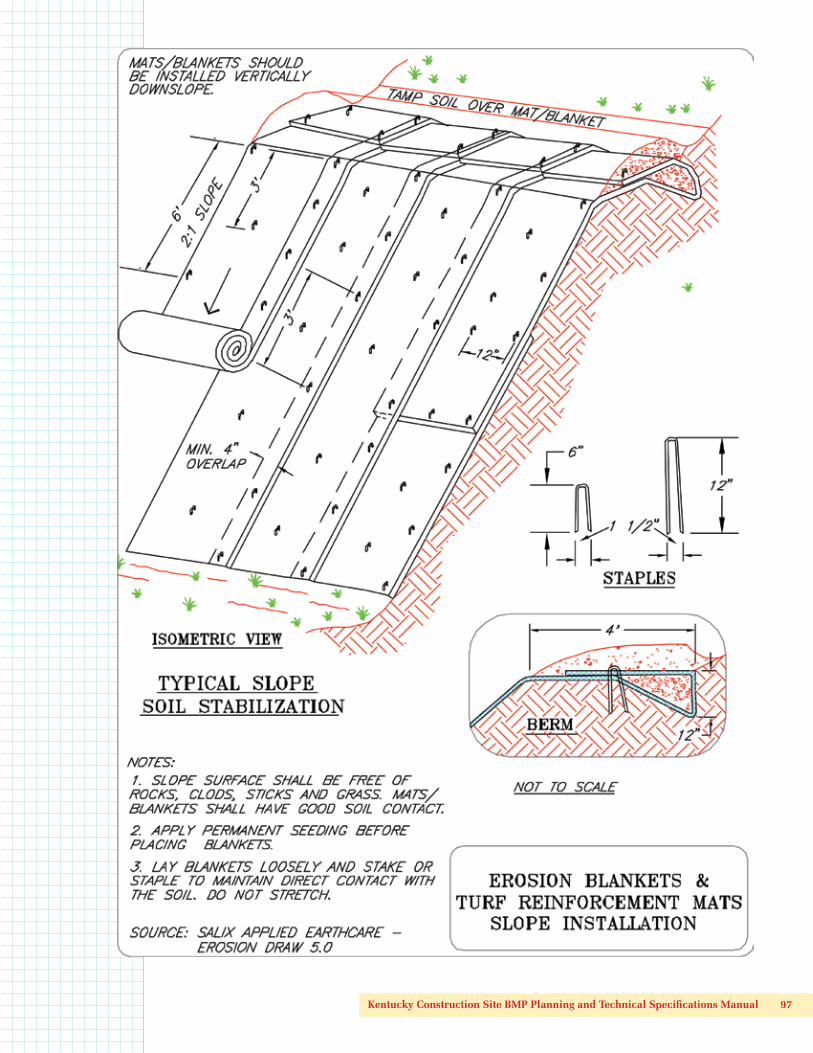
Installation on Slopes
Begin at the top of the slope and anchor the blanket in a 6 inch deep by 6 inch wide trench. Backfill trench and tamp earth firmly.
• Unroll blanket downslope in the direction of the water flow.
• The edges of adjacent parallel rolls must be overlapped at least 3 inches and be stapled through the overlapped area at least every 3 feet on slopes less than 4H:1V and every 2 feet on steeper slopes.
• When blankets must be spliced, place uphill blanket end over downhill blanket (shingle style) with 6-inch overlap. Staple through overlapped area, approximately 12 inches apart.
• Lay blankets and mats loosely and maintain direct contact with the soil—do not stretch. Ensure good, consistent, direct soil contact.
• ECBs and TRMs must be stapled sufficiently to anchor the blanket and maintain contact with the soil. Staples must be placed down the center and staggered with the staples placed along the edges. Steep slopes (1H:1V to 2H:1V) require at least two staples per square yard. Moderate slopes (2H:1V to 3H:1H) require 1-2 staples per square yard (1 staple 3 every feet on center). Gentle slopes require one staple per square yard.
Install blankets and mats vertically on long slopes. Trench and staple top section, overlap sides 3 to 6 inches. Follow manufacturer’s directions regarding stapling and slope limitations. For areas that will be mowed, specify blankets without plastic netting or material designed to decompose within 6 months.
Kentucky Construction Site BMP Planning and Technical Specifications Manual 91
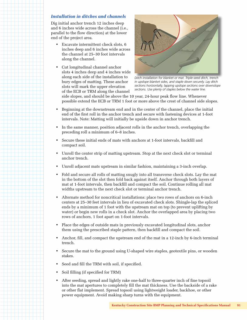
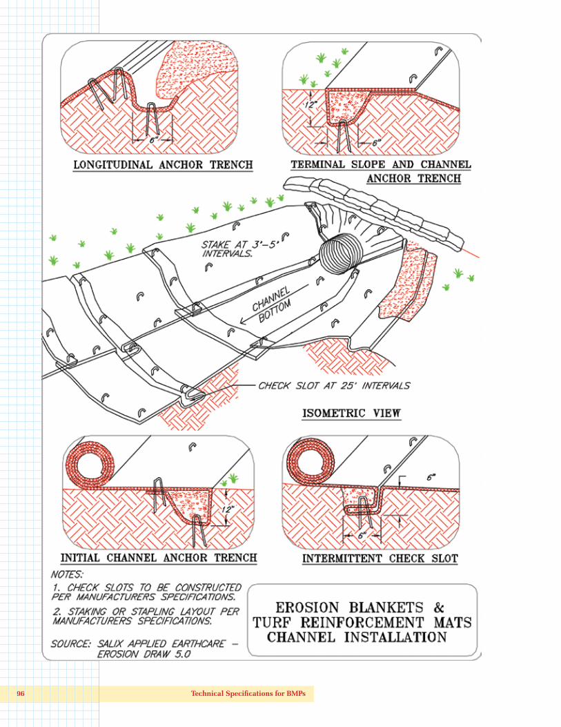
Installation in ditches and channels
Dig initial anchor trench 12 inches deep and 6 inches wide across the channel (i.e., parallel to the flow direction) at the lower end of the project area.
• Excavate intermittent check slots, 6 inches deep and 6 inches wide across the channel at 25–30 foot intervals along the channel.
• Cut longitudinal channel anchor slots 4 inches deep and 4 inches wide along each side of the installation to bury edges of matting. These anchor slots will mark the upper elevation of the ECB or TRM along the channel side slopes, and should be above the 10 year, 24-hour peak flow line. Whenever possible extend the ECB or TRM 1 foot or more above the crest of channel side slopes.
• Beginning at the downstream end and in the center of the channel, place the initial end of the first roll in the anchor trench and secure with fastening devices at 1-foot intervals. Note: Matting will initially be upside down in anchor trench.
• In the same manner, position adjacent rolls in the anchor trench, overlapping the preceding roll a minimum of 6–8 inches.
• Secure these initial ends of mats with anchors at 1-foot intervals, backfill and compact soil.
• Unroll the center strip of matting upstream. Stop at the next check slot or terminal anchor trench.
• Unroll adjacent mats upstream in similar fashion, maintaining a 3-inch overlap.
• Fold and secure all rolls of matting snugly into all transverse check slots. Lay the mat in the bottom of the slot then fold back against itself. Anchor through both layers of mat at 1-foot intervals, then backfill and compact the soil. Continue rolling all mat widths upstream to the next check slot or terminal anchor trench.
• Alternate method for noncritical installations: place two rows of anchors on 6-inch centers at 25–30 feet intervals in lieu of excavated check slots. Shingle-lap the spliced ends by a minimum of 1 foot with the upstream mat on top (to prevent uplifting by water) or begin new rolls in a check slot. Anchor the overlapped area by placing two rows of anchors, 1 foot apart on 1-foot intervals.
• Place the edges of outside mats in previously excavated longitudinal slots, anchor them using the prescribed staple pattern, then backfill and compact the soil.
• Anchor, fill, and compact the upstream end of the mat in a 12-inch by 6-inch terminal trench.
• Secure the mat to the ground using U-shaped wire staples, geotextile pins, or wooden stakes.
• Seed and fill the TRM with soil, if specified.
• Soil filling (if specified for TRM)
• After seeding, spread and lightly rake one-half to three-quarter inch of fine topsoil into the mat apertures to completely fill the mat thickness. Use the backside of a rake or other flat implement. Spread topsoil using lightweight loader, backhoe, or other power equipment. Avoid making sharp turns with the equipment.
Ditch installation for blanket or mat. Triple-seed ditch, trench in upslope blanket sides, and staple down securely. Lay ditch sections horizontally, lapping upslope sections over downslope sections. Use plenty of staples below the water line.

92 Technical Specifications for BMPs
Ero
sio
n C
on
tro
l Te
chn
olo
gy C
ou
nci
l Sta
nd
ard
Sp
eci
fica
tio
n f
or
Tem
po
rary
Ro
lled
Ero
sio
n C
on
tro
l Pro
du
cts
For
use
wh
ere
nat
ura
l veg
etat
ion
alo
ne
will
pro
vid
e p
erm
anen
t er
osi
on
pro
tect
ion
ULT
RA
SH
OR
T TE
RM
: Typ
ical
3-M
on
th F
un
ctio
nal
Lo
ng
evit
y
Typ
ePr
od
uct
D
escr
ipti
on
Mat
eria
l Co
mp
osi
tio
nSl
op
e A
pp
licat
ion
s*C
han
nel
Ap
plic
atio
ns*
Min
imu
mTe
nsi
le S
tren
gth
1M
axim
umG
radi
ent
C F
acto
r 2,
5Pe
rmis
sibl
e Sh
ear
Stre
ss 3,
4, 6
1.A
Mul
ch C
ontr
ol
Net
sA
pho
tode
grad
able
syn
thet
ic m
esh
or w
oven
bio
degr
adab
le
natu
ral fi
ber
nett
ing.
5:1
(H:V
)<
0.1
0 @
5:1
= 0
.25
lbs/
ft2
5 lb
s/ft
1.B
Net
less
Rol
led
ECBs
Nat
ural
and
/or
poly
mer
fibe
rs m
echa
nica
lly in
terlo
cked
and
/or
che
mic
ally
adh
ered
tog
ethe
r to
for
m a
REC
P.4:
1 (H
:V)
< 0
.10
@ 4
:1=
0.5
lbs/
ft2
5 lb
s/ft
1.C
Sing
le-n
et E
CBs
&
Ope
n W
eave
Te
xtile
s
Proc
esse
d de
grad
able
nat
ural
and
/or
poly
mer
fibe
rs
mec
hani
cally
bou
nd t
oget
her
by a
sin
gle
rapi
dly
degr
adin
g,
synt
hetic
or
natu
ral fi
ber
nett
ing
or a
n op
en w
eave
tex
tile
of p
roce
ssed
rap
idly
deg
radi
ng n
atur
al o
r po
lym
er y
arns
or
twin
es w
oven
into
a c
ontin
uous
mat
rix.
3:1
(H:V
)<
0.1
5 @
3:1
= 1
.5 lb
s/ft
250
lbs/
ft
1.D
Dou
ble-
net
ECBs
Proc
esse
d de
grad
able
nat
ural
and
/or
poly
mer
fibe
rs
mec
hani
cally
bou
nd t
oget
her
betw
een
two
rapi
dly
degr
adin
g, s
ynth
etic
or
natu
ral fi
ber
nett
ings
.
2:1
(H:V
)<
0.2
0 @
2:1
= 1
.75
lbs/
ft2
75 lb
s/ft
SHO
RT-
TER
M: T
ypic
al 1
2-M
on
th F
un
ctio
nal
Lo
ng
evit
y
Typ
ePr
od
uct
D
escr
ipti
on
Mat
eria
l Co
mp
osi
tio
nSl
op
e A
pp
licat
ion
s*C
han
nel
Ap
plic
atio
ns*
Min
imu
mTe
nsi
le S
tren
gth
1M
axim
umG
radi
ent
C F
acto
r 2,
5Pe
rmis
sibl
e Sh
ear
Stre
ss 3,
4, 6
2.A
Mul
ch C
ontr
ol
Net
sA
pho
tode
grad
able
syn
thet
ic m
esh
or w
oven
bio
degr
adab
le
natu
ral fi
ber
nett
ing.
5:1
(H:V
)<
0.1
0 @
5:1
= 0
.25
lbs/
ft2
5 lb
s/ft
2.B
Net
less
Rol
led
ECBs
Nat
ural
and
/or
poly
mer
fibe
rs m
echa
nica
lly in
terlo
cked
and
/or
che
mic
ally
adh
ered
tog
ethe
r to
for
m a
REC
P.4:
1 (H
:V)
< 0
.10
@ 4
:1=
0.5
lbs/
ft2
5 lb
s/ft
2.C
Sing
le-n
et E
CBs
&
Ope
n W
eave
Te
xtile
s
An
eros
ion
cont
rol b
lank
et c
ompo
sed
of p
roce
ssed
de
grad
able
nat
ural
or
poly
mer
fibe
rs m
echa
nica
lly b
ound
to
geth
er b
y a
sing
le d
egra
dabl
e sy
nthe
tic o
r na
tura
l fibe
r ne
ttin
g to
for
m a
con
tinuo
us m
atrix
or
an o
pen
wea
ve t
extil
e co
mpo
sed
of p
roce
ssed
deg
rada
ble
natu
ral o
r po
lym
er y
arns
or
tw
ines
wov
en in
to a
con
tinuo
us m
atrix
.
3:1
(H:V
)<
0.1
5 @
3:1
= 1
.5 lb
s/ft
250
lbs/
ft
2.D
Dou
ble-
net
ECBs
Proc
esse
d de
grad
able
nat
ural
and
/or
poly
mer
fibe
rs
mec
hani
cally
bou
nd t
oget
her
betw
een
two
degr
adab
le,
synt
hetic
or
natu
ral fi
ber
nett
ings
.
2:1
(H:V
)<
0.2
0 @
2:1
= 1
.75
lbs/
ft2
75 lb
s/ft

Kentucky Construction Site BMP Planning and Technical Specifications Manual 93
Ero
sio
n C
on
tro
l Te
chn
olo
gy C
ou
nci
l Sta
nd
ard
Sp
eci
fica
tio
n f
or
Tem
po
rary
Ro
lled
Ero
sio
n C
on
tro
l Pro
du
cts
(co
nti
nu
ed
)Fo
r u
se w
her
e n
atu
ral v
eget
atio
n a
lon
e w
ill p
rovi
de
per
man
ent
ero
sio
n p
rote
ctio
n
EXTE
ND
ED T
ERM
: Typ
ical
24-
Mo
nth
Fu
nct
ion
al L
on
gev
ity
Typ
ePr
od
uct
D
escr
ipti
on
Mat
eria
l Co
mp
osi
tio
nSl
op
e A
pp
licat
ion
s*C
han
nel
Ap
plic
atio
ns*
Min
imu
mTe
nsi
le S
tren
gth
1M
axim
umG
radi
ent
C F
acto
r 2,
5Pe
rmis
sibl
e Sh
ear
Stre
ss 3,
4, 6
3.A
Mul
ch C
ontr
ol
Net
sA
slo
w d
egra
ding
syn
thet
ic m
esh
or w
oven
nat
ural
fibe
r ne
ttin
g.5:
1 (H
:V)
< 0
.10
@ 5
:1=
0.2
5 lb
s/ft
225
lbs/
ft
3.B
ECBs
& O
pen
Wea
ve T
extil
esA
n EC
B co
mpo
sed
of p
roce
ssed
slo
w d
egra
ding
nat
ural
or
poly
mer
fibe
rs m
echa
nica
lly b
ound
tog
ethe
r be
twee
n tw
o sl
ow d
egra
ding
syn
thet
ic o
r na
tura
l fibe
r ne
ttin
gs t
o fo
rm
a co
ntin
uous
mat
rix o
r an
ope
n w
eave
tex
tile
com
pose
d of
pro
cess
ed s
low
deg
radi
ng n
atur
al o
r po
lym
er y
arns
or
twin
es w
oven
into
a c
ontin
uous
mat
rix.
1.5:
1 (H
:V)
< 0
.25
@ 1
.5.:1
= 2
.00
lbs/
ft2
100
lbs/
ft
LON
G T
ERM
: Typ
ical
36-
Mo
nth
Fu
nct
ion
al L
on
gev
ity
Typ
ePr
od
uct
D
escr
ipti
on
Mat
eria
l Co
mp
osi
tio
nSl
op
e A
pp
licat
ion
s*C
han
nel
Ap
plic
atio
ns*
Min
imu
mTe
nsi
le S
tren
gth
1M
axim
umG
radi
ent
C F
acto
r 2,
5Pe
rmis
sibl
e Sh
ear
Stre
ss 3,
4, 6
4EC
Bs &
Ope
n W
eave
Tex
tiles
An
ECB
com
pose
d of
pro
cess
ed s
low
deg
radi
ng n
atur
al o
r po
lym
er fi
bers
mec
hani
cally
bou
nd t
oget
her
betw
een
two
slow
deg
radi
ng s
ynth
etic
or
natu
ral fi
ber
nett
ings
to
form
a
cont
inuo
us m
atrix
or
an o
pen
wea
ve t
extil
e co
mpo
sed
of p
roce
ssed
slo
w d
egra
ding
nat
ural
or
poly
mer
yar
ns o
r tw
ines
wov
en in
to a
con
tinuo
us m
atrix
.
1:1
(H:V
)<
0.2
5 @
1:1
= 2
.25
lbs/
ft2
125
lbs/
ft
NO
TES:
* “C
” fa
ctor
and
she
ar s
tres
s fo
r Ty
pes
1.A
., 2.
A. a
nd 3
.A m
ulch
con
trol
net
tings
mus
t be
obt
aine
d w
ith n
ettin
g us
ed in
con
junc
tion
with
pre
-app
lied
mul
ch m
ater
ial.
1 M
inim
um A
vera
ge R
oll V
alue
s w
hen
test
ed in
the
mac
hine
dire
ctio
n us
ing
ECTC
Mod
ified
AST
M D
503
5.
2 Fa
ctor
cal
cula
ted
as r
atio
of
soil
loss
fro
m R
ECP
prot
ecte
d sl
ope
(tes
ted
at s
peci
fied
or g
reat
er g
radi
ent,
H:V
) to
ratio
of
soil
loss
fro
m u
npro
tect
ed (c
ontr
ol) p
lot
in la
rge-
scal
e te
stin
g. P
erfo
rman
ce
test
val
ues
shou
ld b
e su
ppor
ted
by p
erio
dic
benc
h sc
ale
test
ing
unde
r si
mila
r te
st c
ondi
tions
usi
ng E
CTC
Tes
t M
etho
d #
2.
3 M
inim
um s
hear
str
ess
REC
P (u
nveg
etat
ed) c
an s
usta
in w
ithou
t ph
ysic
al d
amag
e or
exc
ess
eros
ion
(0.5
in s
oil l
oss)
dur
ing
a 30
-min
ute
flow
eve
nt in
larg
e-sc
ale
test
ing.
Per
form
ance
tes
t va
lues
sh
ould
be
supp
orte
d by
per
iodi
c be
nch-
scal
e te
stin
g un
der
sim
ilar
test
con
ditio
ns a
nd f
ailu
re c
riter
ia u
sing
EC
TC T
est
Met
hod
#3.
4 Th
e pe
rmis
sibl
e sh
ear
stre
ss le
vels
est
ablis
hed
for
each
per
form
ance
cat
egor
y ar
e ba
sed
on h
isto
rical
exp
erie
nce
with
pro
duct
s ch
arac
teriz
ed b
y M
anni
ng’s
roug
hnes
s co
effic
ient
s in
the
ran
ge o
f 0.
01–0
.05.
5 A
ccep
tabl
e la
rge-
scal
e te
st m
etho
ds m
ay in
clud
e A
STM
D64
59 o
r ot
her
inde
pend
ent
test
ing
deem
ed a
ccep
tabl
e by
the
eng
inee
r.
6 A
ccep
tabl
e la
rge-
scal
e te
stin
g pr
otoc
ol m
ay in
clud
e A
STM
D64
60 o
r ot
her
inde
pend
ent
test
ing
deem
ed a
ccep
tabl
e by
the
eng
inee
r.

94 Technical Specifications for BMPs
Ero
sio
n C
on
tro
l Te
chn
olo
gy C
ou
nci
l Sta
nd
ard
Sp
eci
fica
tio
n f
or
Perm
an
en
t R
oll
ed
Ero
sio
n C
on
tro
l Pro
du
cts
For
app
licat
ion
s in
dit
ches
an
d c
han
nel
s, a
nd
on
slo
pes
no
t ex
ceed
ing
0.5
H:1
V w
her
e ve
get
atio
n a
lon
e w
ill n
ot
sust
ain
exp
ecte
d fl
ow
co
nd
itio
ns
and
/or
pro
vid
e su
ffici
ent
lon
g-t
erm
ero
sio
n p
rote
ctio
n
Typ
e1Pr
od
uct
Des
crip
tio
nM
ater
ial C
om
po
siti
on
Min
imu
mTe
nsi
le S
tren
gth
2, 3
Min
imu
m T
hic
knes
s(A
STM
D 6
525)
UV
Sta
bili
ty(A
STM
D 4
355
@ 5
00 H
ou
rs)
Ch
ann
el
Ap
plic
atio
ns
Perm
issi
ble
Sh
ear
Stre
ss 4,
5
5.A
TRM
Long
ter
m, n
on-d
egra
dabl
e ro
lled
eros
ion
cont
rol
prod
uct
com
pose
d of
UV
sta
biliz
ed,
nond
egra
dabl
e, s
ynth
etic
fibe
rs, fi
lam
ents
, ne
ttin
gs a
nd/o
r w
ire m
esh
proc
esse
d in
to t
hree
dim
ensi
onal
rei
nfor
cem
ent
mat
rices
des
igne
d fo
r pe
rman
ent
and
criti
cal h
ydra
ulic
app
licat
ions
whe
re d
esig
n di
scha
rges
exe
rt v
eloc
ities
and
she
ar s
tres
ses
that
exc
eed
the
limits
of
mat
ure,
nat
ural
ve
geta
tion.
TRM
s pr
ovid
e su
ffici
ent
thic
knes
s, s
tren
gth
and
void
spa
ce t
o pe
rmit
soil
fillin
g an
d/or
ret
entio
n an
d th
e de
velo
pmen
t of
ve
geta
tion
with
in t
he m
atrix
.
125
lbs/
ft0.
25 in
ches
80%
= 6
.0 lb
s/ft
2
5.B
TRM
150
lbs/
ft0.
25 in
ches
80%
= 8
.0 lb
s/ft
2
5.C
TRM
175
lbs/
ft0.
25 in
ches
80%
= 1
0.0
lbs/
ft2
NO
TES:
1 Fo
r TR
Ms
cont
aini
ng d
egra
dabl
e co
mpo
nent
s, a
ll pr
oper
ty v
alue
s m
ust
be o
btai
ned
on t
he n
on-d
egra
dabl
e po
rtio
n of
the
mat
ting
alon
e.
2 M
inim
um A
vera
ge R
oll V
alue
s, m
achi
ne d
irect
ion
only
for
ten
sile
str
engt
h de
term
inat
ion
usin
g A
STM
D68
18 (S
uper
sede
s M
od. A
STM
D50
35 f
or R
ECPs
)
3 Fi
eld
cond
ition
s w
ith h
igh-
load
ing
and/
or h
igh
surv
ivab
ility
req
uire
men
ts m
ay w
arra
nt t
he u
se o
f a
TRM
with
a t
ensi
le s
tren
gth
of 3
,000
lb/f
t or
gre
ater
.
4 Sh
ear
stre
ss t
hat
fully
veg
etat
ed T
RM c
an s
usta
in w
ithou
t ph
ysic
al d
amag
e or
exc
ess
eros
ion
(0.5
in) s
oil l
oss)
dur
ing
a 30
-min
ute
flow
in la
rge-
scal
e te
stin
g.
5 A
ccep
tabl
e la
rge-
scal
e te
stin
g pr
otoc
ol m
ay in
clud
e A
STM
D64
60 o
r ot
her
inde
pend
ent
test
ing
deem
ed a
ccep
tabl
e by
the
eng
inee
r.

Kentucky Construction Site BMP Planning and Technical Specifications Manual 95
• Do not drive tracked or heavy equipment over the mat. Avoid any traffic over the matting if loose or wet soil conditions exist.
• Use shovels, rakes or brooms for fine grading and touch up. Smooth out soil filling, just exposing the top netting of matrix.
Inspection and MaintenanceAll blankets and mats should be inspected periodically following installation.
• Inspect installation after significant rainstorms to check for erosion and undermining. Any failure should be repaired immediately.
• If washout or breakage occurs, reinstall the material after repairing the damage to the slope or drainageway.
Erosion control blankets (top right) are thinner and degrade quicker than turf reinforcement mats (lower left). Blankets are used on shorter, flatter slopes and low-flow ditches. Mats can be used on steep slopes and high-velocity ditches.
Blankets are highly recommended for long, steep slopes (i.e., longer than 75 feet and steeper than 3H:1V). Trench in top of blankets, overlap sides, and use plenty of staples. Blankets can become saturated and heavy after a rain and begin to slip down the slope if not staked securely.
Very good installation of turf mat in long, steep, high-flow ditch below long slope.
Good use of straw and excelsior blankets on streambank stabilization project. Note that the bottom of stream is not disturbed to preserve habitat. This site is ready for live stakes, tree plantings, or other vegetation (see Section 4.7, Stream and Wetland Protection).
Seeding on long, steep slope protected by straw erosion control blanket. Make sure blankets are stapled down securely for these
applications to prevent blankets from sliding downhill when weighted down with rain and fugitive sediment.
96 Technical Specifications for BMPs
Kentucky Construction Site BMP Planning and Technical Specifications Manual 97

98 Technical Specifications for BMPs
4.5 Slope Protection
4.5.4 Temporary Slope Drains
DefinitionA temporary slope drain is a pipe or lined (TRM, rock, or concrete) ditch or channel extending from the top to the bottom of a cut or fill slope during the construction period.
PurposeTemporary slope drains serve to convey concentrated runoff down the face of a cut or fill slope without causing erosion. They are generally used in conjunction with diversions to convey runoff down a slope until permanent water management measures can be installed.
Design Criteria Use the design criteria below for both pipe and channel slope drains. For channels, see the section on Channels and Ditches for information on lining temporary and permanent slope drains constructed as open conveyances.
General—It is very important that these temporary structures be sized, installed, and maintained properly, because their failure will usually result in severe erosion of the slope. The entrance section to the drain should be well entrenched, staked down, and stable so that surface water can enter freely. The drain should extend downslope beyond the toe of the slope to a stable area or appropriately stabilized outlet.
Pipe capacity—The pipe should be able to handle peak flow from the 10-year, 24-hour storm. Use 10-inch diameter or larger pipe to convey runoff from areas up to one-third acre; 12-inch or larger pipe for up to half-acre drainage areas, and 18-inch pipe for areas up to one acre. Multiple pipes or channels are often required for large areas, spaced as needed.
Conduit—Construct the slope drain pipes from heavy-duty, flexible materials such as non-perforated, corrugated plastic pipe, or open top overside drains with tapered inlets, or corrugated metal pipe (CMP). Install reinforced, hold-down grommets or stakes to anchor the conduit at intervals not to exceed 10 feet with the outlet end securely fastened in place. CMP or corrugated plastic pipe must have one anchor assembly for every 20 feet of slope drain. The conduit must extend beyond the toe of the slope.
Entrance—Construct the entrance to the slope drain of a standard flared-inlet section of pipe with a minimum 6-inch metal toe plate. Make all fittings watertight. A standard T-section fitting can also be used at the inlet. An open top flared inlet for overside drain can also be used.
Temporary diversion—Generally, use an earthen diversion with a dike ridge or berm to direct surface runoff into the temporary slope drain. Make the height of the ridge over the drain conduit a minimum of 1.5 feet and at least 6 inches higher than the adjoining ridge
Securely installed plastic pipe functions very well as a temporary slope drain. Inspect after rainfall to make sure flows are routed into drain pipe, and outlet areas are stable and not eroding.
Kentucky Construction Site BMP Planning and Technical Specifications Manual 99
on either side. The lowest point of the diversion ridge should be a minimum of 1 foot above the top of the drain so that design flow can freely enter the pipe.
Outlet protection—Protect the outlet of the slope drain from erosion with an energy dissipator. (i.e., rock apron or other armoring).
Construction SpecificationsA common failure of slope drains is caused by water saturating the soil and seeping along the pipe. Proper backfilling around and under the pipe haunches with stable soil material and hand-compacting in 6 inch lifts to achieve firm contact between the pipe and the soil at all points will reduce this type of failure.
• Place slope drains on undisturbed soil or well-compacted fill at locations and elevations shown on the plans.
• Slightly slope the section of pipe under the dike toward its outlet.
• Compact the soil under and around the entrance section in lifts not to exceed 6 inches.
• Ensure that fill over the drain at the top of the slope has a minimum depth of 1.5 feet and a minimum top width of 4 feet. The sides should have a 3H:1V slope.
• Ensure that all slope drain connections are watertight.
• Ensure that all fill material is well compacted. Securely fasten the exposed section of the drain with grommets or stakes spaced no more than 10 feet apart.
• Extend the drain beyond the toe of the slope and adequately protect the outlet from erosion.
• Make the settled, compacted dike ridge no less than 1 foot higher than the top of the pipe inlet.
Immediately stabilize all disturbed areas following construction.
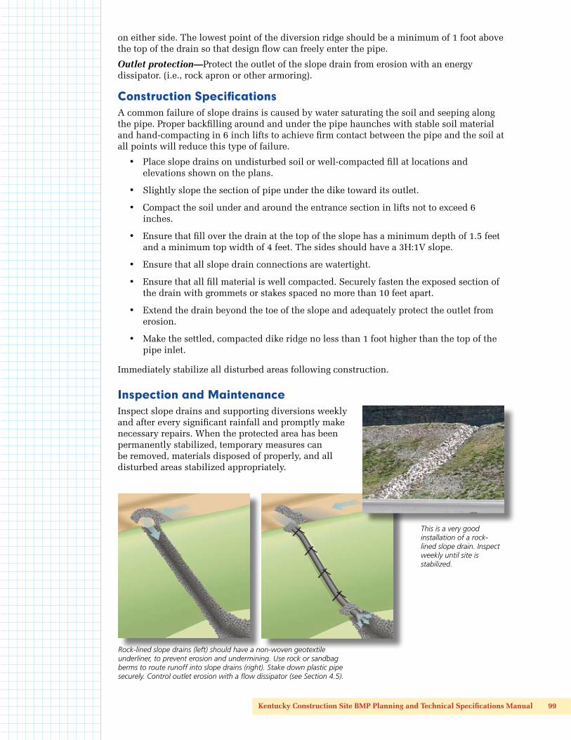
Inspection and MaintenanceInspect slope drains and supporting diversions weekly and after every significant rainfall and promptly make necessary repairs. When the protected area has been permanently stabilized, temporary measures can be removed, materials disposed of properly, and all disturbed areas stabilized appropriately.
Rock-lined slope drains (left) should have a non-woven geotextile underliner, to prevent erosion and undermining. Use rock or sandbag berms to route runoff into slope drains (right). Stake down plastic pipe securely. Control outlet erosion with a flow dissipator (see Section 4.5).
This is a very good installation of a rock-lined slope drain. Inspect weekly until site is stabilized.

100 Technical Specifications for BMPs
Kentucky Construction Site BMP Planning and Technical Specifications Manual 101
4.5 Slope Protection
4.5.5 Gabion Baskets and Mattresses
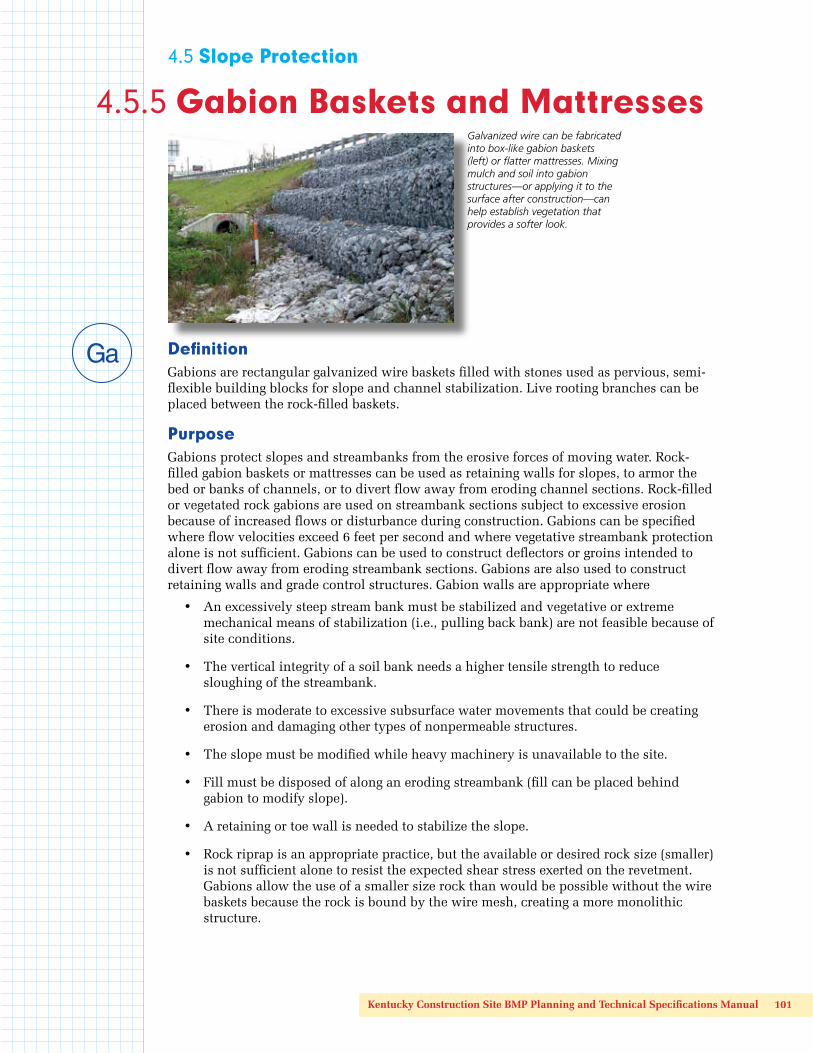
DefinitionGabions are rectangular galvanized wire baskets filled with stones used as pervious, semi-flexible building blocks for slope and channel stabilization. Live rooting branches can be placed between the rock-filled baskets.
PurposeGabions protect slopes and streambanks from the erosive forces of moving water. Rock-filled gabion baskets or mattresses can be used as retaining walls for slopes, to armor the bed or banks of channels, or to divert flow away from eroding channel sections. Rock-filled or vegetated rock gabions are used on streambank sections subject to excessive erosion because of increased flows or disturbance during construction. Gabions can be specified where flow velocities exceed 6 feet per second and where vegetative streambank protection alone is not sufficient. Gabions can be used to construct deflectors or groins intended to divert flow away from eroding streambank sections. Gabions are also used to construct retaining walls and grade control structures. Gabion walls are appropriate where
• An excessively steep stream bank must be stabilized and vegetative or extreme mechanical means of stabilization (i.e., pulling back bank) are not feasible because of site conditions.
• The vertical integrity of a soil bank needs a higher tensile strength to reduce sloughing of the streambank.
• There is moderate to excessive subsurface water movements that could be creating erosion and damaging other types of nonpermeable structures.
• The slope must be modified while heavy machinery is unavailable to the site.
• Fill must be disposed of along an eroding streambank (fill can be placed behind gabion to modify slope).
• A retaining or toe wall is needed to stabilize the slope.
• Rock riprap is an appropriate practice, but the available or desired rock size (smaller) is not sufficient alone to resist the expected shear stress exerted on the revetment. Gabions allow the use of a smaller size rock than would be possible without the wire baskets because the rock is bound by the wire mesh, creating a more monolithic structure.
Galvanized wire can be fabricated into box-like gabion baskets (left) or flatter mattresses. Mixing mulch and soil into gabion structures—or applying it to the surface after construction—can help establish vegetation that provides a softer look.
102 Technical Specifications for BMPs
Design CriteriaThere are several types of gabion structures and applications useful on construction sites, as summarized below. Gabion structures are not recommended for steeply sloping channels where rock or high volumes of gravel sediment move at high velocity in the channel bed because of the possibility of damage to the wire mesh and failure of the basket or mattress structure.
Gabion wall—Basically a gravity wall that relies on its own weight and frictional resistance to resist sliding and overturning from lateral earth pressure.
Vegetated rock gabion—A rock-filled gabion earth-retaining structure that has live branches placed between each consecutive layer of rock-filled baskets. The live branches will take root inside the gabion and into the soil behind the structure. The vegetation will consolidate the structures and bind it to the slope.
Gabion deflector—Deflector or groins project into the streams and divert flows away from eroding streambank sections.
Gabion aprons—Rock-filled gabions or gabion mattress used as outlet protection, energy dissipators, or spillways. These semiflexible gabions are designed to settle without fracturing and adhere to the ground if scour occurs.
Grade control—Drop structures or weirs. Gabion baskets and mattresses can be combined to construct check dams or weirs.
Channel lining—Gabion mattresses can be used to line channels. The lining thickness depends on many factors such as the type of rock, design flow velocity, sediment and bedload, and channel gradient.
Gabion mattresses—Also referred to as Reno mattresses or revet mattresses, gabion mattresses are not as thick as gabions, usually one-half, three-quarters, or 1 foot thick. Gabion mattresses are used to line channels, armor streambanks and slopes, and used with gabions for grade-control structures (spillways or aprons).
Gabions and gabion mattresses are often preferable to rock riprap alone. For any given hydraulic condition, the gabion or gabion mattress revetment thickness is one-third of an equivalent riprap design. Gabions and gabion mattresses are flexible and free draining, thus allowing some soil settling. They can be used in unstable streambeds and streambanks. Gabions can provide an important component to a bioengineering solution for streambank or slope erosion because they allow the growth and establishment of natural vegetation.
Gabion containers are generally fabricated from a double-twist, hexagonal mesh of heavily zinc-coated wire. Some gabions use welded wire. As an option, the wire can be coated with PVC. Wire diameter is 0.086 inches for the double-twisted gabion mattress and 0.106–0.120 inches for the double-twisted gabion. The welded wire gabion uses wire diameters of 0.120 inches or greater. The rectangular gabions are divided into cells with diaphragms of equal capacity. The compartments add strength and assure that the full material remains evenly distributed. Gabions and gabion mattresses come in various sizes.
Choose the dimensions of the gabions or combination of gabions to meet the design requirement site conditions. The mesh opening for gabions is typically or nominally 3.25 x 4.5 inches. Some gabion mattresses have mesh openings of approximately 2.5 x 3.25 inches. Both styles perform hydraulically equivalent.
The use of gabion structures in urban areas is not recommended, because of the possibility that they will harbor rodents and other pests. Some counties and cities in Kentucky have banned gabion structures except in extreme conditions, where no other material is appropriate.

Kentucky Construction Site BMP Planning and Technical Specifications Manual 103
Typical Gabion Basket Sizes
Letter Code Length (ft)
Width (ft)
Depth (ft)
Number of Cells
Capacity (cubic yards)
A 6 3 3 1 2
B 9 3 3 2 3
C 12 3 3 3 4
D 6 3 1.5 1 1
E 9 3 1.5 2 1.5
F 12 3 1.5 3 2
G 6 3 1 1 0.666
H 9 3 1 2 1
I 12 3 1 3 1.333
T 9 6 .75 3 2.0
U 12 6 .75 4 1.33
Q 9 6 .5 3 1.33
S 9 6 .5 2 1.0
Construction SpecificationsInstall gabions in accordance with manufacturer’s standards and specifications.
• Gabions must be fabricated so that the sides, ends, lid and diaphragms can be assembled at the construction site into rectangular baskets of the sizes specified and shown on the construction drawings.
• Gabions must be of single-unit construction; the base, lid, ends and sides must be either woven into a single unit or one edge of these members connected to the base section of the gabion so that the strength and flexibility at the connecting point is at least equal to that of the mesh.
• Where the length of the gabion exceeds 1.5 times its horizontal width, the gabion must be divided by diaphragms of the same mesh and gauge as the body of the gabion, into cells whose length does not exceed the horizontal width.
• Gabions and mattresses are unfolded and assembled at the job site. Corners are first joined together and then the diaphragms are attached to the side panels.
• Each gabion must be assembled by tying all untied edges with lacing wire or approved fasteners. The lacing wire must be tightly looped around every other mesh opening along the seams so that single and double loops are alternated.
• The gabion or gabion mattress must be securely keyed into the streambank or streambed to assure that flows do not erode the soils beneath or around it.
• Starting at the lowest point of the slope, excavate the loose material 2–3 feet below the ground elevation until a stable foundation is reached.
• Excavate the back of the stable foundation slightly deeper than the front so the foundation tilts back into the slope.
• A line of empty gabion units must be placed in the bottom of its excavation and the baskets are to be joined together along adjacent edges, both horizontally and vertically. The base of the empty gabions placed on top of a filled line of gabions must be tightly wired to the latter at front and back.

104 Technical Specifications for BMPs
• To achieve better alignment and finish in gabion walls, stretching of the gabions is recommended.
• For gabions greater than 18 inches, connecting wires (wires tied to opposite faces of each gabion cell) must be installed during filling operations.
• Hand-packing the gabion baskets or mattresses is preferred, but mechanical filling is acceptable if care is taken to avoid bending, distorting, or damaging the wire structures. Gabions must be filled to a depth of 12 inches and then two connecting wires must be tightly tied to opposite faces of each gabion cell at a height of 12 inches above the base. Gabions must then be filled with a further depth of 12 inches and two connecting wires must be similarly tied at this level. Then gabions must be filled to the top.
• Fill gabions with appropriately sized river rock or quarry stone or other approved infill material. Use of hard material with high specific gravity is recommended. The tops of the gabions are then closed along edges and diaphragms using lacing wire or approved fasteners. Keep voids and bulges in the gabions to a minimum to ensure proper alignment and a neat, compact, square appearance.
• The stone size to fill gabions must be 3–5 inches for gabion mattresses and 4–8 inches for gabion baskets.
Inspection and MaintenanceInspection of construction methods during the gabion assembly, placement, and fill process will help ensure that the structure performs as intended. All structures should be maintained in an as built condition. Structural damage caused by storm events should be repaired as soon as possible to prevent further damage to the structure or erosion of the streambank.
During inspection, look for undercutting, bypassing, or other flow-related erosion problems. Check to ensure that basket wiring is adequate, and components are not separating (i.e., sidewalls becoming detached). Repair baskets that appear to be splitting; use rock or other armoring to repair eroded areas.
Gabions can protect banks in areas of high velocity flows. Some designers prefer TRMs in these situations, if space is available to slope banks back appropriately.
Gabion mattresses can replace turf mats in high-flow, high-velocity channels. Mixing mulch and soil into the rock can help support vegetation for a “greener” look.

Kentucky Construction Site BMP Planning and Technical Specifications Manual 105

106 Technical Specifications for BMPs
4.5 Slope Protection
4.5.6 Cellular Confinement Systems
DefinitionA cellular confinement system (CCS) is a three-dimensional, honeycombed, sheet, mat, or interlocking structure filled with soil and planted with vegetation used to stabilize the surface of earthen cut and fill slopes.
PurposeCCSs are permanent erosion control practices intended to stabilize infill materials for slope and channel protection, load support, and earth retention applications. The expandable panels create a cellular system that confines topsoil infill, protects and reinforces the plant’s root zone, and permits infiltration and natural subsurface drainage. The honeycomb shaped cells encapsulate and prevent erosion of the infill material. The cellular confinement systems are used for
• Revetments—Filling the cells with topsoil or rock and vegetation can provide an alternative to hard armor revetment systems
• Erosion control on steep slopes—Cells can be filled with soil and vegetated or filled with granular materials. Slopes as steep as 1H:1V can be treated with cellular confinement systems. Application on steep slopes may require tendons for system stability and security against sliding.
• Flexible channel lining systems—either vegetated or rock filled.
• Road stabilization—cells confine and reinforce select fill materials, thereby increasing load-bearing capacities. Creates a porous pavement system with aggregate or topsoil/vegetation infill.
• Temporary low-water stream crossings.
Construction SpecificationsSite Preparation
The surface of the slope should be leveled, with stones and debris removed. Gullies should be filled and well compacted. Major obstacles such as boulders can be left in place. Simply cut out panels around them.
Following excavation and fill placement operations, shape and compact the subgrade surfaces to the designed elevations and grades.
Excavate the area so that when cellular confinement systems are installed, the top of the section is flush with or slightly lower than the adjacent terrain or final grade.
Remove unstable subgrade soils when required and install geotextile underliner if specified.
Concrete and plastic cellular blankets, like this open-celled concrete block product, provide heavy armoring while supporting vegetation that softens the final look.
Kentucky Construction Site BMP Planning and Technical Specifications Manual 107
InstallationFollow manufacturer’s instructions regarding application type, slope limits, installation procedure, appropriate fill material, and so on.
• Anchor the cellular confinement system sections at the top of the slope across a 2–4 foot ledge. Expand and stretch the cellular confinement system down the slopes.
• The type of anchors and frequency of anchoring will depend on site conditions. Typically, every other cell across the top section is anchored with J-pins or other suitable anchor devices. This anchoring pattern is repeated every 6 feet down the slope.
• The cells should be anchored securely to prevent deformation of the panel while backfilling. Depending on the slope angle and fill soils involved, intermediate anchorage will be necessary on some interior cells to limit sideways deformation, ensure stability and avoid overloading the upper sections.
• Additional panels are abutted together and joined with staples, hog rings or other suitable fasteners.
Infill PlacementPlace the fill material in the expanded cells with suitable equipment such as a backhoe, front-end loader or conveyer.
• Limit drop height to 3 feet to reduce crushing force on cell material.
• On steep slopes, infill from the crest to the toe to prevent displacement and deformation of the cellular confinement system.
• Overfilling and compacting of infill depend on the type and consistency of material and the depth of the cells.
Inspection and Maintenance Inspect slope periodically and after significant rainstorms to check for erosion. Any failure should be repaired immediately.
If vegetation has not been established, fertilize and reseed damaged and sparse areas immediately.
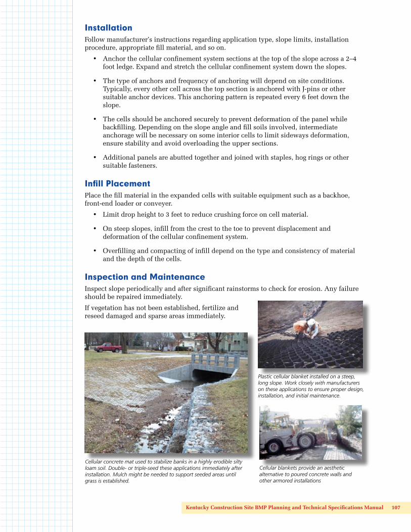
Cellular concrete mat used to stabilize banks in a highly erodible silty loam soil. Double- or triple-seed these applications immediately after installation. Mulch might be needed to support seeded areas until grass is established.
Plastic cellular blanket installed on a steep, long slope. Work closely with manufacturers on these applications to ensure proper design, installation, and initial maintenance.
Cellular blankets provide an aesthetic alternative to poured concrete walls and other armored installations